FUSELAGE-MOUNTED FINS ON THE STATIC DIRECTIONAL STABILITY. By M. Leroy Spearman, Ross B. Robinson, and Cornelius Driver
|
|
|
- Felix Roberts
- 5 years ago
- Views:
Transcription
1 RESEARCH MEMORANDUM THE EFFECTS OF THE ADDITION OF SMALL FUSELAGE-MOUNTED FINS ON THE STATIC DIRECTIONAL STABILITY CHARACTERISTICS OF A MODEL OF A 45' SWEPT-WING AIRPLANE AT ANGLES OF ATTACK UP TO 15.3? AT A MACH NUMBER OF 2.1 By M. Leroy Spearman, Ross B. Robinson, and Cornelius Driver Langley Aeronautical Laboratory Langley Field, Va. 1 f NATIONAL ADVISORY COMMITTEE FOR AERONAUTICS m WASHINGTON October 12, 1956
2 ~ 1B rl NACA RM L56Dl6a NATIONAL ADVISORY COMI- FOR AERONAUTICS 'J RESMCH MEMORANDUM THE EFFM='lS OF TRE ADDITION OF SMALL FUSELAGE-MOUNTED FINS ON THE STATIC DmTIONAL STABILITY CHARACTERISTICS OF A MODEL OF A 45' SWEPT-WING AIFPLCWE AT ANGLES OF ATTACK UP To 15.3' AT A MACH NUMBER OF 2.1 By M. Leroy Spearman, Ross B. Robinson, and Cornelius Driver SUMMARY k 1 d Tests have been made in the Langley 4- by 4-foot supersonic pressure tunnel at a Mach number of 2.1to determine the effects of the addition of four small'fuselage-mounted cruciform fins on the directional characteristics of a 45' swept-wing airplane model at angles of attack up to 15.3' and angles of sideslip up to about 16'. The results showed that the addition of the four cruciform fins to the model increased the directional stability substantially at the highest angle of attack and, at the same time, caused relatively small changes in drag. I"I!RODUCTION 1. d Among the problems of supersonic aircraft is that of maintaining sufficient directional stability, particularly at high angles of attack. For this reason, tests have been made in the Langley 4- by 4-foot supersonic pressure tunnel at a Mach number of 2.1 of a 45' swept-wing fighter-type airplane model to which four small cruciform fins were added for the purpose of augmenting the directional stability. The fin arrangement investigated was suggested by the Republic Aviation Corporation. The fins, which extended over the rear 31percent of the fuselage, were about the size and shape of a conventional ventral fin and were located in a cruciform arrangement in planes at 45O to the horizontal
3 and verticalplanes. The fins had a combined area of 76.6 percent of the vertical-tail area. The fins were tested in conjunction with a normal vertical tail and ventral fin. Ln addition, various cambinations of the cruciform fins, the ventral fin, and the vertical tail were made. All tests were made with the wing on and with air flow through the wingroot inlets. SYMBOLS The results are presented as coefficients of forces and moments with the moment reference point located at 25 percent of the wing mean geometric chord. The yawing moment, rolling moment, and side force are referred to the body-axis system and the lift, drag, and pitching mament are referred to the stability-axis system. The symbols are defined as follows : Lift lift coefficient, - qs rag (approximate) drag coefficient (approximate), qs equivalent to true drag at p = Pitching mament pitching-mament coefficient, Yawing moment yawing=mament coefficient, qsb Rolling moment rolling -moment coefficient, q=.p I side-force coefficient, Side force qs free-stream dynamic pressure wing area,.795 sq ft wing chord wing mean geametric chord,.522 ft wing span, 1.59 ft 4 V
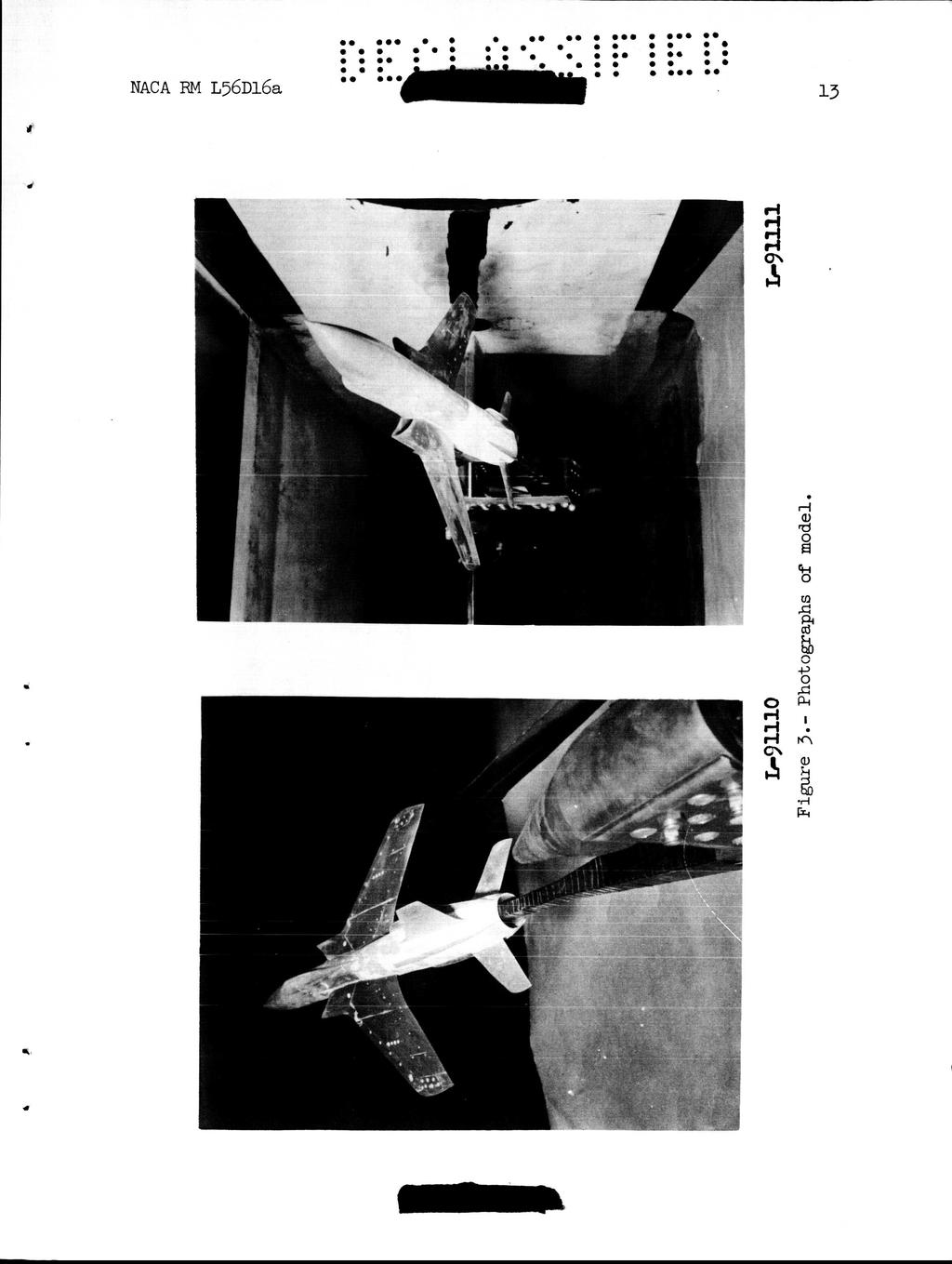
4 P a C C 2P cyp F V U angle of sideslip, deg angle of attack, deg rate of change of yawing-mament coefficient with angle of sideslip (p = ), &n/ap rate of change of rolling-moment coefficient with angle of sideslip (p ), &ZPP rate of change of side-force coefficient with angle of sideslip (P = 1, acy/ap cruciform fins vertical tail ventral fin MODEL AND AF'PARADJS?. d I. d A three-view drawing of the model is shown in figure 1. Details of the four cruciform fins are shown in figure 2. Photographs of the model showing the cruciform fins installed are presented in figure 3. Some geometric characteristics for the model are presented in table I. The model had a wing with 45' sweepback at the quarter-chord line, an aspect ratio of 3.2, and a taper ratio of.468. The wing was composed of NACA 6%-series sections having thickness ratios of 5.5 percent just outboard of the inlet (.38bj2) and 3.7 percent at the tip. The wing was located slightly above the fuselage center line and the horizontal tail was mounted below the fuselage center line. The stabilizer incidence angle was fixed at -3'. The model was equipped with twin wingroot supersonic inlets ducted to a single exit at the base of the body. All tests were made with air flow through the ducts with a mass-flow ratio of about.8. The four cruciform fins were attached in planes at 45' to the horizontal and vertical planes and were arbitrarily shaped and positioned so that their span would cause no increase in the projected side area of the afterbody. As indicated in figure 2(a), the lower fins were slightly asymmetric at the model base. Forces and moments were measured by means of a six-component internal strain-gage balance.
5 4 NACA RM L56Dl6a TESTS Test Conditions and Procedure It t The tests were made at a Mach number of 2.1, a stagnation pressure of 5 pounds per square inch absolute, and a stagnation temperature of LOOo F. The dew point was maintained sufficiently low (below -25' F) so that no condensation effects were encountered in the test section. The Reynolds number based on a mean aerodynamic chord of.522 foot was about 644,. Tests were made through an angle-of-sideslip range fram about -4' to about 16 at angles of attack, primarily, of Oo and 15.3O. CORRECTIONS AND ACCURACY The angles of attack and sideslip have been corrected for deflections of the balance and sting under load.. The drag coefficients have been adjusted to correspond to the condition of free-stream static pressure at the model base. The measured drag was corrected to account for the internal drag and for an internal buoyant force on the balance so that a net external drag was obtained. The estimated errors in the individual measured quantities are as follows : CL... ia.73 CD'... f.11 c,.... fo.23 c,.... m.3 c p.... ~.2 cy..... ~.2 u,deg... to. 1 p,deg * PRESENTATION OF RESULTS The results are presented in the following manner: tail... Figure 4 L!! V
6 Effects of top pair and bottom pair of fins at a = 15.3', vertical tail and ventral fin on... Effects of top left and bottom right fins at a = 15.3O, vertical tail and ventral fin on... Effects of ventral fin at a = ' and 13.3', vertical tail and four cruciform fins on... Effects of ventral fin and four cruciform fins with the vertical tail off, a = Oo and 15.3'... Effects of four cruciform fins on lift, drag and pitchingmoment variations with sideslip at a = ' and 1>.3', vertical tail and ventral fin on... Summary of sideslip derivatives for various fin and tail arrangements... Summary of directional stability increments provided by vertical tail, cruciform fins, and ventral fin... DISCUSSION Directional Characteristics Figure g Effects of cruciform fins.- The effects of the addition of the four cruciform fins to the model are presented in figure 4 and summarized in figure 1. The addition of the four fins to the cmplete model (vertical tail and ventral fin on) caused only a slight increase in directional s t abi lity at a = '. However, the directional stability was ( ".e) increased significantly at a = 15.3' where a reflex in the variation of C, with p near p = Oo was removed by the addition of the four fins. (See fig. J+(c).) The addition of either the top pair or bottam pair of fins separately at a = 15.3' provides about half the increase in directional stability as that provided by all four fins. (See figs. 5 and 1.) "he nature of the cruciform fin effect on the directional stability at a = 15.3O may be seen by comparing the configuration without fins with the configuration equipped with the top left and bottom right fins (fig. 6). At p = ", the inclination of these fins is such that a component of force is directed in the positive side-force direction and provides a negative yawing moment. Throughout the negative sideslip range, these fins remain in a plane inclined to the stream direction and provide an increased stabilizing increment of yawing moment. Through the positive sideslip range, however, these fins tend to move into the plane of the relative stream direction and thus provide essentially no
7 change in Cn above about p = 2'. Thus, it is apparent that the upper and lower fins on both sides are required to provide the maximum effectiveness in increasing the restoring yawing moments throughout the sideslip range. 1 c The variations with angle of attack of the incremental cnp contri- butions for the various configurations (fig. 11) indicate a rather rapid decrease in effectiveness of the vertical tail. The ventral fin effectiveness also decreases with angle of attack but to a lesser extent. The effectiveness of the four cruciform fins, on the other hand, increases with increasing angle of attack. All tests were made with the wing-root inlets open. Any effects of these inlets on the directional characteristics are believed to be small, however, since no significant disturbance from the inlets in the region of the tail was visible in schlieren or vapor screen views of the model. Effects of ventral fin.- The complete-model results thus far have included a conventional ventral fin on the body center line as a part of the vertical stabilizing surfaces. Since ventral fins may cause some restriction to the ground clearance angle, it would be desirable, if practical, to eliminate such surfaces. Accordingly, some tests were made at a = Oo and 15.3' with the ventral fin removed but with the four cruciform fins and the vertical tail on. These results (fig. 7) indicate some reduction in directional stability at a = Oo, but the level of stability is sufficiently high at this angle so as not to be critical even without the ventral. At a = 15.3', the removal of the ventral fin had very little effect on the directional stability, particularly at small sideslip angles where there is essentially no change in the. Thus, it appears that it would be practical to remove the CnP ventral fin without any significant effect on the directional stability. The effects of the ventral fin and of the four cruciform fins were also determined at a = ' and 13.3' for the configuration with the vertical tail removed. These results (fig. 8) indicate that the increment in C, provided by the ventral alone is about half that provided by the ventral fin and the four cruciform fins combined. Lift, Drag, and Pitchingdment Characteristics There is no appreciable change in the variations of CL, CD', or C, with p resulting from the addition of the four fins (fig. 9). The drag-coefficient increment due to the fins at a = ' is about.2. At a = l5.3', the increment indicated in CD is probably a result of 4 Y
8 .. *.*. NACA RM L36Dl6a 7 the increment in CL change in drag. so that for a constant lift there would be little Lateral Force and Effective Dihedral The effect of the cruciform fins and the ventral fin was to increase the lateral-force derivative Cy in a manner consistent with the attend- P ant directional-stability changes (fig. 1). There was no significant change in the effective dihedral at a = ' (fig. lo), although the value obtained at a = l5.3o was somewhat greater with the fins on than with the fins off. CONCUTSIONS Tests made to determine the effects of the addition of four small fuselage-mounted cruciform fins on the directional characteristics of a 45' swept-wing airplane model at a Mach number of 2.1 indicated the following conclusions: 1. "he addition of the four cruciform fins to the model, although it caused only a slight increase in directional stability at zero angle of attack, provided a substantial increase in the directional stability at the highest angle of attack (15.3') primarily because of direct forces on the fins. 2. The effectiveness of either the upper pair or lower pair of fins alone was about half that for all four fins together. 3. Removing the conventional ventral fin had no significant effect on the directional stability of the configuration with the four cruciform fins. 4. The addition of the four cruciform fins caused an increase in the drag coefficient at zero angle of attack of about.2. Langley Aeronautical Laboratory, National Advisory Committee for Aeronautics, Langley Field, Va., April 3, 1956.
9 NACA RM L56D16a a TABU 1.- GEx)ME'IRIC CHARACTERISTICS OF MODEL Y Area. including body intercept. sq ft span. ft Mean geanetric chord. ft Aspect ratio Taper ratio Sweep. quarter-chord line. deg Dihedral. deg Theoretical root chord at body center line. in Theoretical tip chord. in Airfoil sections: 13.8-percent semispan station NACA 65~5.5 Theoretical tip... NACA 65~3.7 wing:... span. ft... Aspect ratio... Taper ratio line. in Airfoil sections: Root... Tip... Horizontal t ai 1: Area including body intercept. sq ft Sweep. quarter-chord line. deg... Theoretical root chord at body center Theoretical tip chord. in NACA 65~6 NACA 65AOO4 Vertical tail: Area to body center line. sq ft span. ft Aspect ratio Taper ratio Sweep of leading edge. deg Theoretical root chord at body center line. in Theoretical tip chord. in Ventral: Area (exposed). sq ft Fuselage fin: Area one. exposed) sq ft Area t four. exposedj. sq ft r,
10 IU 9 y! rn
11 1 NACA RM L56D16a c
12 c *' 4,
13 12 NACA REI L56D16a c I
14 iyi A '
15 14 NACA RM L56D16a.8.m.4.a c, O 4.I CY ' -;I A (a) a 5 QO. Figure 4.- Aerodynamic characteristics in sideslip for various fin arrangements at several angles of attack.

16 .w -.2 c, - I -.2.I CY -.I c J P, deg (b) u = 1'. Figure 4.- Continued.
17 16.6 Cn SM m On On On On A Off Off U Cl I CY -.I P,W (c) u = 15.3'. Figure 4.- Concluded.

18 3B a? Cn -2 1 c, -.o I -2-3.I CY -.I P, deg Figure 5.- Effect of top pair and bottan pair of fins on sideslip characteristics with vertical tail and ventral fin on. a = 15.3O.

19 18 NACA RM L36D16a.O 4.o 2 8 J Cn o c, 3 -.o I.2-2.I -3 CY -.I , deg Figure 6.- Effect of top left and bottom right fins on sideslip characteristics with vertical tail and ventral fin on. a = 15.3O.
20 I.6.w Cn c, - I -.2.I CY -.I -.2 Y a -4 4 a 12 is 2 P, deg (a) a = '. Figure 7.- Effect of ventral fin on sideslip characteristics at two angles of attack with the vertical tail and four cruciform fins on. \ i
21 2.a.4 Cn.w -2 DI c, - I -2.I CY O -.I a P, deg (b) u = 15.3'. Figure - 7, Concluded.
22 21 '.2 V c,o -.o I c.i c cv -.I P, deg (a) a = '. Figure 8.- Effect of ventral fin and four cruciform fins on sideslip characteristics at two angles of attack with the vertical tail off.
 u = 13.3'. Figure 8.- Concluded. _.")
23 22 NACA RM ~36D16a.6 r'.2 Cn -.2 Cl -.o I -.2.I CY -.I a -4 4 a P, deg (b) u = 13.3'. Figure 8.- Concluded. _._
24 NACA RM L36D16a moo P, deg (a) a = '. Figure 9.- Effect of four cruciform fins on lift, drag, and pitchingmoment variations with sideslip at two angles of attack with the vertical tail and ventral fin on. d

25 24 (b) u = 13.3'. Figure 9.- Concluded. L

26 4B. W Vertiwl on on Off Off On On m Off tail c , deg Figure 1.- Summary of sideslip derivatives for various fin and tail arrangements.
27 26 b.4 (AC 2.2 F U on on I off on -- J n- KI -- (ACn )U P.2 I ' Ktfftftttf Ventral fin contribution I U v on off -- Figure ll.- Incremental values of Cn for various configurations. B NACA - Langley Field, VJ
RESEARCH MEMORANDUM. WASHINGTON December 3, AERODYNl$MIC CHARACTERISTICS OF A MODEL? OF AN ESCAPE ...,
 .". -.%. ;& RESEARCH MEMORANDUM AERODYNl$MIC CHARACTERISTICS OF A MODEL? OF AN ESCAPE 1 \ < :. By John G. Presnell, Jr. w'..., '.., 3... This material contains information affecting the National Bfense
RESEARCH MEMORANDUM FOR AERONAUTICS HAVING A TRZANGULAR WING OF ASPECT WETI0 3. Moffett Field, Calif. WASHINGTON. Ames Aeronautical Laboratory
 RESEARCH MEMORANDUM THE EFFECTS OF TRAILINGEDGE FLAPS ON THE SUBSONIC AERODYNAMIC CHARACTERISTICS OF AN AIRPLANE MODEL HAVING A TRZANGULAR WING OF ASPECT WETI0 3 By Bruce E. Tinling and A. V. I I Ames
Aircraft Design: A Systems Engineering Approach, M. Sadraey, Wiley, Figures
 Aircraft Design: A Systems Engineering Approach, M. Sadraey, Wiley, 2012 Chapter 5 Wing Design Figures 1 Identify and prioritize wing design requirements (Performance, stability, producibility, operational
THE COLLEGE OF AERONAUTICS CRANFIELD
 THE COLLEGE OF AERONAUTICS CRANFIELD AERODYNAMIC CHARACTERISTICS OF A 40 SWEPT BACK WING OF ASPECT RATIO 4.5 by P. S. BARNA NOTE NO. 65 MAY, 1957 CRANFIELD A preliminary report on the aerodynamic characteristics
RESEARCH MEMORANDUM NATIONAL ADVISORY COMMITTEE FOR AERONAUTICS .'. L. ' By Gerald V. Foster " WASHINGTON March 6, 1958
 RESEARCH MEMORANDUM INVESTIGATION OF THE LONGITUDINAL AERODYNAMIC CHARACTERISTICS OF A TRAPEZOIDAL-WING AIRPLANE MODEL WITH VAF?IOUS VERTICAL POSITIONS OF WING AND HORIZONTAL TAIL AT MACH NUMBERS OF 1.41
NATIONAL '-ADVISORY COMMITTEE FOR AERONAUTICS I I...,,. :-, [a (: I' <V>* d J WASHINGTON. Bureau of Aeronautics, Department of the Navy.
 ~,,. for the Bureau of Aeronautics, Department of the Navy WIND-TUNNEL IMTESTIGATION AT LOW SPEED OF THE ROLLING STABILITY DERIVATIVES OF A l/lo-scale MODEL OF THE DOUGLAS A4D-1 AntPLANE TED NO. NACA DE
Chapter 5 Wing design - selection of wing parameters - 4 Lecture 22 Topics
 Chapter 5 Wing design - selection of wing parameters - Lecture Topics 5.3.9 Ailerons 5.3.0 Other aspects of wing design Example 5. 5.3.9 Ailerons The main purpose of the ailerons is to create rolling moment
Aerodynamics Principles
 Aerodynamics Principles Stage 1 Ground Lesson 3 Chapter 3 / Pages 2-18 3:00 Hrs Harold E. Calderon AGI, CFI, CFII, and MEI Lesson Objectives Become familiar with the four forces of flight, aerodynamic
It should be noted that the symmetrical airfoil at zero lift has no pitching moment about the aerodynamic center because the upper and
 NAVWEPS -81-8 and high power, the dynamic pressure in the shaded area can be much greater than the free stream and this causes considerably greater lift than at zero thrust. At high power conditions the
IMPACT OF FUSELAGE CROSS SECTION ON THE STABILITY OF A GENERIC FIGHTER
 IMPACT OF FUSELAGE CROSS SECTION ON THE STABILITY OF A GENERIC FIGHTER Robert M. Hall NASA Langley Research Center Hampton, Virginia ABSTRACT Many traditional data bases, which involved smooth-sided forebodies,
AERODYNAMIC CHARACTERISTICS OF SPIN PHENOMENON FOR DELTA WING
 ICAS 2002 CONGRESS AERODYNAMIC CHARACTERISTICS OF SPIN PHENOMENON FOR DELTA WING Yoshiaki NAKAMURA (nakamura@nuae.nagoya-u.ac.jp) Takafumi YAMADA (yamada@nuae.nagoya-u.ac.jp) Department of Aerospace Engineering,
C-1: Aerodynamics of Airfoils 1 C-2: Aerodynamics of Airfoils 2 C-3: Panel Methods C-4: Thin Airfoil Theory
 ROAD MAP... AE301 Aerodynamics I UNIT C: 2-D Airfoils C-1: Aerodynamics of Airfoils 1 C-2: Aerodynamics of Airfoils 2 C-3: Panel Methods C-4: Thin Airfoil Theory AE301 Aerodynamics I : List of Subjects
Preliminary Design Review (PDR) Aerodynamics #2 AAE-451 Aircraft Design
 Aerodynamics #2 AAE-451 Aircraft Design") Preliminary Design Review (PDR) Aerodynamics #2 AAE-451 Aircraft Design Aircraft Geometry (highlight any significant revisions since Aerodynamics PDR #1) Airfoil section for wing, vertical and horizontal
Preliminary Design Review (PDR) Aerodynamics #2 AAE-451 Aircraft Design Aircraft Geometry (highlight any significant revisions since Aerodynamics PDR #1) Airfoil section for wing, vertical and horizontal
DEC2B 194P a»»> v&* NATIONAL ADVISORY COMMITTEE FOR AERONAUTICS WARTIME REPORT ORIGINALLY ISSUED
 DEC2B 194P a»»> v&* NATIONAL ADVISORY COMMITTEE FOR AERONAUTICS WARTIME REPORT ORIGINALLY ISSUED /' October 19^5 as Restricted Bulletin Lf?I0f> "DSE OF VARIABLE-RATIO GEARED TABS TO IMPROVE STICK-FORCE
ROAD MAP... D-1: Aerodynamics of 3-D Wings D-2: Boundary Layer and Viscous Effects D-3: XFLR (Aerodynamics Analysis Tool)
") Unit D-1: Aerodynamics of 3-D Wings Page 1 of 5 AE301 Aerodynamics I UNIT D: Applied Aerodynamics ROAD MAP... D-1: Aerodynamics of 3-D Wings D-: Boundary Layer and Viscous Effects D-3: XFLR (Aerodynamics
Unit D-1: Aerodynamics of 3-D Wings Page 1 of 5 AE301 Aerodynamics I UNIT D: Applied Aerodynamics ROAD MAP... D-1: Aerodynamics of 3-D Wings D-: Boundary Layer and Viscous Effects D-3: XFLR (Aerodynamics
Aerodynamic Terms. Angle of attack is the angle between the relative wind and the wing chord line. [Figure 2-2] Leading edge. Upper camber.
![Aerodynamic Terms. Angle of attack is the angle between the relative wind and the wing chord line. [Figure 2-2] Leading edge. Upper camber.](/thumbs/82/86661300.jpg "Aerodynamic Terms. Angle of attack is the angle between the relative wind and the wing chord line. [Figure 2-2] Leading edge. Upper camber.") Chapters 2 and 3 of the Pilot s Handbook of Aeronautical Knowledge (FAA-H-8083-25) apply to powered parachutes and are a prerequisite to reading this book. This chapter will focus on the aerodynamic fundamentals
Chapters 2 and 3 of the Pilot s Handbook of Aeronautical Knowledge (FAA-H-8083-25) apply to powered parachutes and are a prerequisite to reading this book. This chapter will focus on the aerodynamic fundamentals
Stability and Flight Controls
 Stability and Flight Controls Three Axes of Flight Longitudinal (green) Nose to tail Lateral (blue) Wing tip to Wing tip Vertical (red) Top to bottom Arm Moment Force Controls The Flight Controls Pitch
Aero Club. Introduction to Flight
 Aero Club Presents Introduction to RC Modeling Module 1 Introduction to Flight Centre For Innovation IIT Madras Page2 Table of Contents Introduction:... 3 How planes fly How is lift generated?... 3 Forces
Lift for a Finite Wing. all real wings are finite in span (airfoils are considered as infinite in the span)
") Lift for a Finite Wing all real wings are finite in span (airfoils are considered as infinite in the span) The lift coefficient differs from that of an airfoil because there are strong vortices produced
Lift for a Finite Wing all real wings are finite in span (airfoils are considered as infinite in the span) The lift coefficient differs from that of an airfoil because there are strong vortices produced
Low-Speed Wind-Tunnel Investigation of the Stability and Control Characteristics of a Series of Flying Wings With Sweep Angles of 50
 NASA Technical Memorandum 464 Low-Speed Wind-Tunnel Investigation of the Stability and Control Characteristics of a Series of Flying Wings With Sweep Angles of 5 Scott P. Fears Lockheed Engineering & Sciences
Low Speed Wind Tunnel Wing Performance
 Low Speed Wind Tunnel Wing Performance ARO 101L Introduction to Aeronautics Section 01 Group 13 20 November 2015 Aerospace Engineering Department California Polytechnic University, Pomona Team Leader:
Aircraft Stability and Control Prof. A. K. Ghosh Department of Aerospace Engineering Indian Institute of Technology-Kanpur. Lecture- 25 Revision
 Aircraft Stability and Control Prof. A. K. Ghosh Department of Aerospace Engineering Indian Institute of Technology-Kanpur Lecture- 25 Revision Yes, dear friends, this is the mann ki baat session for lateral
The effect of back spin on a table tennis ball moving in a viscous fluid.
 How can planes fly? The phenomenon of lift can be produced in an ideal (non-viscous) fluid by the addition of a free vortex (circulation) around a cylinder in a rectilinear flow stream. This is known as
No Description Direction Source 1. Thrust
 AERODYNAMICS FORCES 1. WORKING TOGETHER Actually Lift Force is not the only force working on the aircraft, during aircraft moving through the air. There are several aerodynamics forces working together
Investigation on 3-D Wing of commercial Aeroplane with Aerofoil NACA 2415 Using CFD Fluent
 Investigation on 3-D of commercial Aeroplane with Aerofoil NACA 2415 Using CFD Fluent Rohit Jain 1, Mr. Sandeep Jain 2, Mr. Lokesh Bajpai 3 1PG Student, 2 Associate Professor, 3 Professor & Head 1 2 3
Investigation and Comparison of Airfoils
 AENG 360 Aerodynamics Investigation and Comparison of Airfoils Rocie Benavent Chelseyann Bipat Brandon Gilyard Julian Marcon New York Institute of Technology Fall 2013 2 Executive Summary Airfoil design
November 1955 TECHNICAL NOTE 3586 IMPINGEMENT OF WATER DROPLETS ON NACA 65A004. AIRFOIL AT Oo ANGLE OF ATTACK. By Rinaldo J. Brun and Dorothea E.
 TECHNICAL NOTE 3586 IMPINGEMENT OF WATER DROPLETS ON NACA 65A004 AIRFOIL AT Oo ANGLE OF ATTACK By Rinaldo J. Brun and Dorothea E. Vogt Lewis Flight Propulsion Laboratory Cleveland, Ohio, Washington November
DIRECCION DE PERSONAL AERONAUTICO DPTO. DE INSTRUCCION PREGUNTAS Y OPCIONES POR TEMA
 MT DIREION DE PERSONL ERONUTIO DPTO. DE INSTRUION PREGUNTS Y OPIONES POR TEM 1 TEM: 0292 FLT/DSP - (HP. 03) ERODYNMIS OD_PREG: PREG20084823 (8324) PREGUNT: When are inboard ailerons normally used? Low-speed
Chapter 5 Wing design - selection of wing parameters - 3 Lecture 21 Topics
 Chapter 5 Wing design - selection of wing parameters - 3 Lecture 21 Topics 5.3.2 Choice of sweep ( ) 5.3.3 Choice of taper ratio ( λ ) 5.3.4 Choice of twist ( ε ) 5.3.5 Wing incidence(i w ) 5.3.6 Choice
RESEARCH MEMORANDPM. I\OBbRY '3
 - o RESEARCH MEMORANDPM \OBbRY '3 i NATONAL ADVSORY COMMJTTEX FOR AEXONAUTCS RESEARCH MEMORANDUM FRST LAMDNG By Richard E. OF BEXG X-2 RESEAR-&l ARPLANE Day and Wendell H. Stillwell The Bell X-2 supersonic
SUBPART C - STRUCTURE
 SUBPART C - STRUCTURE GENERAL CS 23.301 Loads (a) Strength requirements are specified in terms of limit loads (the maximum loads to be expected in service) and ultimate loads (limit loads multiplied by
External Tank- Drag Reduction Methods and Flow Analysis
 External Tank- Drag Reduction Methods and Flow Analysis Shaik Mohammed Anis M.Tech Student, MLR Institute of Technology, Hyderabad, India. G. Parthasarathy Associate Professor, MLR Institute of Technology,
STUDIES ON THE OPTIMUM PERFORMANCE OF TAPERED VORTEX FLAPS
 ICAS 2000 CONGRESS STUDIES ON THE OPTIMUM PERFORMANCE OF TAPERED VORTEX FLAPS Kenichi RINOIE Department of Aeronautics and Astronautics, University of Tokyo, Tokyo, 113-8656, JAPAN Keywords: vortex flap,
JAR-23 Normal, Utility, Aerobatic, and Commuter Category Aeroplanes \ Issued 11 March 1994 \ Section 1- Requirements \ Subpart C - Structure \ General
 JAR 23.301 Loads \ JAR 23.301 Loads (a) Strength requirements are specified in terms of limit loads (the maximum loads to be expected in service) and ultimate loads (limit loads multiplied by prescribed
Fighter aircraft design. Aerospace Design Project G. Dimitriadis
 Fighter aircraft design Aerospace Design Project 2017-2018 G. Dimitriadis General configuration The elements of the general configuration are the following: Wing Wing placement Airfoil Number of engines
Uncontrolled copy not subject to amendment. Principles of Flight
 Uncontrolled copy not subject to amendment Principles of Flight Principles of Flight Learning Outcome 2: Understand how the stability of an aeroplane is maintained in flight and how manoeuvrability is
DIRECCION DE PERSONAL AERONAUTICO DPTO. DE INSTRUCCION PREGUNTAS Y OPCIONES POR TEMA
 MT DIREION DE PERSONL ERONUTIO DPTO. DE INSTRUION PREGUNTS Y OPIONES POR TEM 1 TEM: 0114 TP - (HP. 03) ERODYNMIS OD_PREG: PREG20078023 (8358) PREGUNT: What is the safest and most efficient takeoff and
LEVEL FOUR AVIATION EVALUATION PRACTICE TEST
 Below you will find a practice test for the Level 4 Aviation Evaluation that covers PO431, PO432, PO436, and PO437. It is recommended that you focus on the material covered in the practice test as you
Aerodynamics of Winglet: A Computational Fluid Dynamics Study Using Fluent
 Aerodynamics of : A Computational Fluid Dynamics Study Using Fluent Rohit Jain 1, Mr. Sandeep Jain, Mr. Lokesh Bajpai 1PG Student, Associate Professor, Professor & Head 1 Mechanical Engineering Department
RESEARCH MEMORANDUM IN THE LANDING CONFIGURATION WIND-TUNNEL INVESTIGATION OF "HE LOW-SPEED STATIC AND
 RESEARCH MEMORANDUM WIND-TUNNEL INVESTIGATION OF "HE LOW-SPEED STATIC AND ROTARY STABILITY DERIVATIVES OF A 0.13-SCALE MODEL OF Tm D3UGLAS D-558-IC ALRPLANh IN THE LANDING CONFIGURATION 1v RESFARCH MEMORANDUM.
ScienceDirect. Investigation of the aerodynamic characteristics of an aerofoil shaped fuselage UAV model
 Available online at www.sciencedirect.com ScienceDirect Procedia Engineering 90 (2014 ) 225 231 10th International Conference on Mechanical Engineering, ICME 2013 Investigation of the aerodynamic characteristics
High Swept-back Delta Wing Flow
 Advanced Materials Research Submitted: 2014-06-25 ISSN: 1662-8985, Vol. 1016, pp 377-382 Accepted: 2014-06-25 doi:10.4028/www.scientific.net/amr.1016.377 Online: 2014-08-28 2014 Trans Tech Publications,
Incompressible Potential Flow. Panel Methods (3)
") Incompressible Potential Flow Panel Methods (3) Outline Some Potential Theory Derivation of the Integral Equation for the Potential Classic Panel Method Program PANEL Subsonic Airfoil Aerodynamics Issues
Incompressible Potential Flow Panel Methods (3) Outline Some Potential Theory Derivation of the Integral Equation for the Potential Classic Panel Method Program PANEL Subsonic Airfoil Aerodynamics Issues
ANALYSIS OF AERODYNAMIC CHARACTERISTICS OF A SUPERCRITICAL AIRFOIL FOR LOW SPEED AIRCRAFT
 ANALYSIS OF AERODYNAMIC CHARACTERISTICS OF A SUPERCRITICAL AIRFOIL FOR LOW SPEED AIRCRAFT P.Sethunathan 1, M.Niventhran 2, V.Siva 2, R.Sadhan Kumar 2 1 Asst.Professor, Department of Aeronautical Engineering,
Wing-Body Combinations
 Wing-Body Combinations even a pencil at an angle of attack will generate lift, albeit small. Hence, lift is produced by the fuselage of an airplane as well as the wing. The mating of a wing with a fuselage
Design and Development of Micro Aerial Vehicle
 Advances in Aerospace Science and Applications. ISSN 2277-3223 Volume 4, Number 1 (2014), pp. 91-98 Research India Publications http://www.ripublication.com/aasa.htm Design and Development of Micro Aerial
WHAT IS GLIDER? A light engineless aircraft designed to glide after being towed aloft or launched from a catapult.
 GLIDER BASICS WHAT IS GLIDER? A light engineless aircraft designed to glide after being towed aloft or launched from a catapult. 2 PARTS OF GLIDER A glider can be divided into three main parts: a)fuselage
Reduction of Skin Friction Drag in Wings by Employing Riblets
 Reduction of Skin Friction Drag in Wings by Employing Riblets Kousik Kumaar. R 1 Assistant Professor Department of Aeronautical Engineering Nehru Institute of Engineering and Technology Coimbatore, India
CFD Study of Solid Wind Tunnel Wall Effects on Wing Characteristics
 Indian Journal of Science and Technology, Vol 9(45), DOI :10.17485/ijst/2016/v9i45/104585, December 2016 ISSN (Print) : 0974-6846 ISSN (Online) : 0974-5645 CFD Study of Solid Wind Tunnel Wall Effects on
Improved Aerodynamic Characteristics of Aerofoil Shaped Fuselage than that of the Conventional Cylindrical Shaped Fuselage
 International Journal of Scientific & Engineering Research Volume 4, Issue 1, January-213 1 Improved Aerodynamic Characteristics of Aerofoil Shaped Fuselage than that of the Conventional Cylindrical Shaped
Aerodynamic Analysis of a Symmetric Aerofoil
 214 IJEDR Volume 2, Issue 4 ISSN: 2321-9939 Aerodynamic Analysis of a Symmetric Aerofoil Narayan U Rathod Department of Mechanical Engineering, BMS college of Engineering, Bangalore, India Abstract - The
Aerodynamic Forces on a Wing in a Subsonic Wind Tunnel. Learning Objectives
 Aerodynamic Forces on a Wing in a Subsonic Wind Tunnel AerodynamicForces Lab -1 Learning Objectives 1. Familiarization with aerodynamic forces 2. Introduction to airfoil/wing basics 3. Use and operation
Jet Propulsion. Lecture-17. Ujjwal K Saha, Ph. D. Department of Mechanical Engineering Indian Institute of Technology Guwahati
 Lecture-17 Prepared under QIP-CD Cell Project Jet Propulsion Ujjwal K Saha, Ph. D. Department of Mechanical Engineering Indian Institute of Technology Guwahati 1 Lift: is used to support the weight of
Aerodynamic Analysis of Blended Winglet for Low Speed Aircraft
 , July 1-3, 2015, London, U.K. Aerodynamic Analysis of Blended Winglet for Low Speed Aircraft Pooja Pragati, Sudarsan Baskar Abstract This paper provides a practical design of a new concept of massive
Welcome to Aerospace Engineering
 Welcome to Aerospace Engineering DESIGN-CENTERED INTRODUCTION TO AEROSPACE ENGINEERING Notes 4 Topics 1. Course Organization 2. Today's Dreams in Various Speed Ranges 3. Designing a Flight Vehicle: Route
LEADING-EDGE VORTEX FLAPS FOR SUPERSONIC TRANSPORT CONFIGURATION -EFFECTS OF FLAP CONFIGURATIONS AND ROUNDED LEADING-EDGES-
 ICAS 2002 CONGRESS LEADING-EDGE VORTEX FLAPS FOR SUPERSONIC TRANSPORT CONFIGURATION -EFFECTS OF FLAP CONFIGURATIONS AND ROUNDED LEADING-EDGES- Kenichi RINOIE*, Dong Youn KWAK**, Katsuhiro MIYATA* and Masayoshi
Principles of glider flight
 Principles of glider flight [ Lecture 2: Control and stability ] Richard Lancaster Email: Richard@RJPLancaster.net Twitter: @RJPLancaster ASK-21 illustrations Copyright 1983 Alexander Schleicher GmbH &
RESEARCH MEMORANDUM EFFECT OF A FUSELAGE ON THE LOW-SPEED LONGITUDINAL \ AERODYNAMIC CHARACTERISTICS OF A 45 SWEPTBACK WING WITH DOUBLE SLOTTED FLAPS
 E $ - k.$ < c < ;.z i :: RESEARCH MEMORANDUM COPY RM L56GO: ( # r EFFECT OF A FUSELAGE ON THE LOW-SPEED LONGTUDNAL \ AERODYNAMC CHARACTERSTCS OF A 45 SWEPTBACK WNG WTH DOUBLE SLOTTED FLAPS By Rodger L.
BUILD AND TEST A WIND TUNNEL
 LAUNCHING INTO AVIATION 9 2018 Aircraft Owners and Pilots Association. All Rights Reserved. UNIT 2 SECTION D LESSON 2 PRESENTATION BUILD AND TEST A WIND TUNNEL LEARNING OBJECTIVES By the end of this lesson,
PRE-TEST Module 2 The Principles of Flight Units /60 points
 PRE-TEST Module 2 The Principles of Flight Units 1-2-3.../60 points 1 Answer the following questions. (20 p.) moving the plane (4) upward / forward. Opposed to that is 1. What are the names of the four
11-1. Horizontal tailplane sizing according to control requirement
 11-1 11 Empennage izing In ection Empennage General Design, the areas of the horizontal and vertical tailplanes were calculated merely with the aid of tail volume coefficients. The tail lever arms were
II.E. Airplane Flight Controls
 References: FAA-H-8083-3; FAA-8083-3-25 Objectives Key Elements Elements Schedule Equipment IP s Actions SP s Actions Completion Standards The student should develop knowledge of the elements related to
AN INVESTIGATION ON VERTICAL TAILPLANE DESIGN
 AN INVESTIGATION ON VERTICAL TAILPLANE DESIGN Fabrizio Nicolosi Pierluigi Della Vecchia Danilo Ciliberti Dep. of Aerospace Engineering University of Naples Federico II Dep. of Aerospace Engineering University
PNEUMATIC CHANNEL WING POWERED-LIFT ADVANCED SUPER- STOL AIRCRAFT
 1st Flow Control Conference 24-26 June 2002, St. Louis, Missouri AIAA 2002-3275 AIAA 2002-3275 PNEUMATIC CHANNEL WING POWERED-LIFT ADVANCED SUPER- STOL AIRCRAFT Robert J. Englar* Georgia Tech Research
J. Szantyr Lecture No. 21 Aerodynamics of the lifting foils Lifting foils are important parts of many products of contemporary technology.
 J. Szantyr Lecture No. 21 Aerodynamics of the lifting foils Lifting foils are important parts of many products of contemporary technology. < Helicopters Aircraft Gliders Sails > < Keels and rudders Hydrofoils
Numerical Investigation of Multi Airfoil Effect on Performance Increase of Wind Turbine
 International Journal of Engineering & Applied Sciences (IJEAS) International Journal of Engineering Applied Sciences (IJEAS) Vol.9, Issue 3 (2017) 75-86 Vol.x, Issue x(201x)x-xx http://dx.doi.org/10.24107/ijeas.332075
AE Dept., KFUPM. Dr. Abdullah M. Al-Garni. Fuel Economy. Emissions Maximum Speed Acceleration Directional Stability Stability.
 Aerodynamics: Introduction Aerodynamics deals with the motion of objects in air. These objects can be airplanes, missiles or road vehicles. The Table below summarizes the aspects of vehicle performance
HEFAT th International Conference on Heat Transfer, Fluid Mechanics and Thermodynamics July 2012 Malta
 HEFAT212 9 th International Conference on Heat Transfer, Fluid Mechanics and Thermodynamics 16 18 July 212 Malta AN EXPERIMENTAL STUDY OF SWEEP ANGLE EFFECTS ON THE TRANSITION POINT ON A 2D WING BY USING
AERODYNAMIC CHARACTERISTICS OF NACA 0012 AIRFOIL SECTION AT DIFFERENT ANGLES OF ATTACK
 AERODYNAMIC CHARACTERISTICS OF NACA 0012 AIRFOIL SECTION AT DIFFERENT ANGLES OF ATTACK SUPREETH NARASIMHAMURTHY GRADUATE STUDENT 1327291 Table of Contents 1) Introduction...1 2) Methodology.3 3) Results...5
SEMI-SPAN TESTING IN WIND TUNNELS
 25 TH INTERNATIONAL CONGRESS OF THE AERONAUTICAL SCIENCES SEMI-SPAN TESTING IN WIND TUNNELS S. Eder, K. Hufnagel, C. Tropea Chair of Fluid Mechanics and Aerodynamics, Darmstadt University of Technology
AE2610 Introduction to Experimental Methods in Aerospace AERODYNAMIC FORCES ON A WING IN A SUBSONIC WIND TUNNEL
 AE2610 Introduction to Experimental Methods in Aerospace AERODYNAMIC FORCES ON A WING IN A SUBSONIC WIND TUNNEL Objectives The primary objective of this experiment is to familiarize the student with measurement
THEORY OF WINGS AND WIND TUNNEL TESTING OF A NACA 2415 AIRFOIL. By Mehrdad Ghods
 THEORY OF WINGS AND WIND TUNNEL TESTING OF A NACA 2415 AIRFOIL By Mehrdad Ghods Technical Communication for Engineers The University of British Columbia July 23, 2001 ABSTRACT Theory of Wings and Wind
Aerospace Design Project. Design of a class-3 Ultralight airplane
 Aerospace Design Project Design of a class-3 Ultralight airplane Ludovic Noels Grigorios Dimitriadis L.Noels@ulg.ac.be gdimitriadis@ulg.ac.be 1. Context Groups from 4 to 5 students will design a class-3
RESEARCH MEMORANDUM. NATIONAL ADVl SORY COMMITTEE FOR AERONAUTICS. AMD TRBrnG-EDGE FUR WASHINGTON. Lang1ey Aeronautical Laboratory LmgLey Field, Va.
 RESEARCH MEMORANDUM LOW-SUBSONIC INVESTIGATION TO DETERMINE THE CHORDWISE PRESSURE DISTRIBUTION AND EFFECTIVENESS OF SPOILERS ON A THIN, LOW-ASPECT-RATIO, UNSWEPT, UN'TAPERED, SEWISPAN WIMG PlND OM THE
Analysis of the Z-wing configuration
 School of Innovation, Design and Engineering BACHELOR THESIS IN AERONAUTICAL ENGINEERING 15 CREDITS, BASIC LEVEL 300 Analysis of the Z-wing configuration Author: Joakim Avén Report code: MDH.IDT.FLYG.0231.2011.GN300.15HP.Ae
Aerodynamic investigations on a wing in ground effect
 Aerodynamic investigations on a wing in ground effect A summary of NLR activities in the Seabus-Hydaer programme W.B. de Wolf Nationaal Lucht- en Ruimtevaartlaboratorium National Aerospace Laboratory NLR
LAPL(A)/PPL(A) question bank FCL.215, FCL.120 Rev PRINCIPLES OF FLIGHT 080
/PPL(A) question bank FCL.215, FCL.120 Rev PRINCIPLES OF FLIGHT 080") PRINCIPLES OF FLIGHT 080 1 Density: Is unaffected by temperature change. Increases with altitude increase. Reduces with temperature reduction. Reduces with altitude increase. 2 The air pressure that acts
PRINCIPLES OF FLIGHT 080 1 Density: Is unaffected by temperature change. Increases with altitude increase. Reduces with temperature reduction. Reduces with altitude increase. 2 The air pressure that acts
BASIC AIRCRAFT STRUCTURES
 Slide 1 BASIC AIRCRAFT STRUCTURES The basic aircraft structure serves multiple purposes. Such as aircraft aerodynamics; which indicates how smooth the aircraft flies thru the air (The Skelton of the aircraft
Application of Low Speed Wind Tunnels in Teaching Basic Aerodynamics
 Journal of Aviation/Aerospace Education & Research Volume 14 Number 2 JAAER Winter 2005 Article 6 Winter 2005 Application of in Teaching Basic Aerodynamics Randolph S. Reynolds Follow this and additional
Experimental and Theoretical Investigation for the Improvement of the Aerodynamic Characteristic of NACA 0012 airfoil
 International Journal of Mining, Metallurgy & Mechanical Engineering (IJMMME) Volume 2, Issue 1 (214) ISSN 232 46 (Online) Experimental and Theoretical Investigation for the Improvement of the Aerodynamic
A103 AERODYNAMIC PRINCIPLES
 A103 AERODYNAMIC PRINCIPLES References: FAA-H-8083-25A, Pilot s Handbook of Aeronautical Knowledge, Chapter 3 (pgs 4-10) and Chapter 4 (pgs 1-39) OBJECTIVE: Students will understand the fundamental aerodynamic
Aerofoil Profile Analysis and Design Optimisation
 Journal of Aerospace Engineering and Technology Volume 3, Issue 2, ISSN: 2231-038X Aerofoil Profile Analysis and Design Optimisation Kondapalli Siva Prasad*, Vommi Krishna, B.B. Ashok Kumar Department
A COMPUTATIONAL STUDY ON THE DESIGN OF AIRFOILS FOR A FIXED WING MAV AND THE AERODYNAMIC CHARACTERISTIC OF THE VEHICLE
 28 TH INTERNATIONAL CONGRESS OF THE AERONAUTICAL SCIENCES A COMPUTATIONAL STUDY ON THE DESIGN OF AIRFOILS FOR A FIXED WING MAV AND THE AERODYNAMIC CHARACTERISTIC OF THE VEHICLE Jung-Hyun Kim*, Kyu-Hong
Effect of Leading- and Trailing-Edge Flaps on Clipped Delta Wings With and Without Wing Camber at Supersonic Speeds
 NASA Technical Memorandum 4542 Effect of Leading- and Trailing-Edge Flaps on Clipped Delta Wings With and Without Wing Camber at Supersonic Speeds Gloria Hernandez, Richard M. Wood, and Peter F. Covell
The Influence of Battle Damage on the Aerodynamic Characteristics of a Model of an Aircraft
 Proceedings of the 26 WSEAS/IASME International Conference on Fluid Mechanics, Miami, Florida, USA, January 18-2, 26 (pp7-76) The Influence of Battle on the Aerodynamic Characteristics of a Model of an
C-130 Reduction in Directional Stability at Low Dynamic Pressure and High Power Settings
 C-130 Reduction in Directional Stability at Low Dynamic Pressure and High Power Settings The C-130 experiences a marked reduction of directional stability at low dynamic pressures, high power settings,
INTERFERENCE EFFECT AND FLOW PATTERN OF FOUR BIPLANE CONFIGURATIONS USING NACA 0024 PROFILE
 Proceedings of the International Conference on Mechanical Engineering 211 (ICME211) 18-2 December 211, Dhaka, Bangladesh ICME11-FL-1 INTERFERENCE EFFECT AND FLOW PATTERN OF FOUR BIPLANE CONFIGURATIONS
Development of Pneumatic Channel Wing Powered-Lift Advanced Super-STOL Aircraft
 AIAA 2002-2929 Development of Pneumatic Channel Wing Powered-Lift Advanced Super-STOL Aircraft Robert J. Englar Georgia Tech Research Institute Aerospace, Transportation & Advanced Systems Lab Atlanta
Drag Divergence and Wave Shock. A Path to Supersonic Flight Barriers
 Drag Divergence and Wave Shock A Path to Supersonic Flight Barriers Mach Effects on Coefficient of Drag The Critical Mach Number is the velocity on the airfoil at which sonic flow is first acquired If
EXPERIMENTAL ANALYSIS OF FLOW OVER SYMMETRICAL AEROFOIL Mayank Pawar 1, Zankhan Sonara 2 1,2
 EXPERIMENTAL ANALYSIS OF FLOW OVER SYMMETRICAL AEROFOIL Mayank Pawar 1, Zankhan Sonara 2 1,2 Assistant Professor,Chandubhai S. Patel Institute of Technology, CHARUSAT, Changa, Gujarat, India Abstract The
AF101 to AF109. Subsonic Wind Tunnel Models AERODYNAMICS. A selection of optional models for use with TecQuipment s Subsonic Wind Tunnel (AF100)
") Page 1 of 4 A selection of optional models for use with TecQuipment s Subsonic Wind Tunnel (AF100) Dimpled Sphere Drag Model (from AF109) shown inside the TecQuipment AF100 Wind Tunnel. Cylinder, aerofoils,
Page 1 of 4 A selection of optional models for use with TecQuipment s Subsonic Wind Tunnel (AF100) Dimpled Sphere Drag Model (from AF109) shown inside the TecQuipment AF100 Wind Tunnel. Cylinder, aerofoils,
Aerobatic Trimming Chart
 Aerobatic Trimming Chart From RCU - Chip Hyde addresses his view of Engine/Motor thrust. I run almost no right thrust in my planes and use the thottle to rudd mix at 2% left rudd. to throttle at idle.
Induced Drag Reduction for Modern Aircraft without Increasing the Span of the Wing by Using Winglet
 International Journal of Mechanical & Mechatronics Engineering IJMME-IJENS Vol:10 No:03 49 Induced Drag Reduction for Modern Aircraft without Increasing the Span of the Wing by Using Winglet Mohammad Ilias
PRESSURE DISTRIBUTION OF SMALL WIND TURBINE BLADE WITH WINGLETS ON ROTATING CONDITION USING WIND TUNNEL
 International Journal of Mechanical and Production Engineering Research and Development (IJMPERD ) ISSN 2249-6890 Vol.2, Issue 2 June 2012 1-10 TJPRC Pvt. Ltd., PRESSURE DISTRIBUTION OF SMALL WIND TURBINE
Measurement of Pressure. The aerofoil shape used in wing is to. Distribution and Lift for an Aerofoil. generate lift due to the difference
 Measurement of Pressure Distribution and Lift for an Aerofoil. Objective The objective of this experiment is to investigate the pressure distribution around the surface of aerofoil NACA 4415 and to determine
The Metric Glider. By Steven A. Bachmeyer. Aerospace Technology Education Series
 The Metric Glider By Steven A. Bachmeyer Aerospace Technology Education Series 10002 Photographs and Illustrations The author wishes to acknowledge the following individuals and organizations for the photographs
Theory of Flight Aircraft Design and Construction. References: FTGU pages 9-14, 27
 Theory of Flight 6.01 Aircraft Design and Construction References: FTGU pages 9-14, 27 Main Teaching Points Parts of an Airplane Aircraft Construction Landing Gear Standard Terminology Definition The airplane
Related Careers: Aircraft Instrument Repairer Aircraft Designer Aircraft Engineer Aircraft Electronics Specialist Aircraft Mechanic Pilot US Military
 Airplane Design and Flight Fascination with Flight Objective: 1. You will be able to define the basic terms related to airplane flight. 2. You will test fly your airplane and make adjustments to improve
STUDY OF MODEL DEFORMATION AND STING INTERFERENCE TO THE AERODYNAMIC ESTIMATIONS OF THE CAE-AVM MODEL
 STUDY OF MODEL DEFORMATION AND STING INTERFERENCE TO THE AERODYNAMIC Min ZHONG, Ganglin WANG, Jun HUA Chinese Aeronautical Establishment #2 Anwai Beiyuan, 100012, Beijing, China Keywords: Aerodynamic design,
Pressure distribution of rotating small wind turbine blades with winglet using wind tunnel
 Journal of Scientific SARAVANAN & Industrial et al: Research PRESSURE DISTRIBUTION OF SMALL WIND TURBINE BLADES WITH WINGLET Vol. 71, June 01, pp. 45-49 45 Pressure distribution of rotating small wind