Before the Environment Court at Auckland ENV-2013-AKL Evidence of John Michael Leman on behalf of Waiheke Marinas Ltd
|
|
|
- Alison Gallagher
- 5 years ago
- Views:
Transcription
1 Before the Environment Court at Auckland ENV-2013-AKL In the Matter of the Resource Management Act 1991 And In the Matter of Notice of Motion under Section 87G requesting the granting of resource consents to Waiheke Marinas Limited to establish a Marina at Matiatia Bay, Waiheke Island, in the Hauraki Gulf Evidence of John Michael Leman on behalf of Waiheke Marinas Ltd Dated 30 April 2014 Richard Brabant/Jeremy Brabant Barristers Broker House, Level 2, 14 Vulcan Lane PO Box 1502, Shortland St Auckland City Ph: Fax: richard@brabant.co.nz/jeremy@brabant.co.nz
2 Introduction 1. My full name is John Michael Leman. I am a Consulting Engineer and hold a Bachelor of Engineering (University of Auckland). I am a Member of the Institute of Professional Engineers New Zealand. 2. I have 32 years experience as an Engineer. My professional services have predominantly comprised marine works, and in particular, marina facilities design. 3. I have been involved in the design of marina developments in New Zealand, Australia, the Pacific, South-East Asia, China and the Middle East. New Zealand projects within the Auckland region include Gulf Harbour and Pine Harbour. 4. My involvement with the Matiatia Marina project commenced in May My commission was to review the design of the April 2011 marina proposal as a result of submissions, particularly those in relation to the wave climate in the bay, ferry wakes and movements, wave protection, recreational/commercial vessel navigation and safety. 5. To further consider wave aspects, a programme of wind and ferry wave measurements was undertaken by MetOcean Solutions 1 and further wave modelling by Cardno 2. These studies, in conjunction with a more in-depth review of acceptable marina wave climate criteria by my consultancy (International Marina Consultants), formed the basis for refinement and finalisation of the marina facilities proposal. 6. I have visited the site on several occasions including March 2014 where I visited other possible marina sites around Waiheke Island that were raised as potential alternative marina development locations. 7. I have read and agree to abide by the Environment Court s Code of Conduct for Expert Witnesses as specified in the Environment Court s Consolidated 1 MetOcean Solutions report P dated March 2012 entitled Matiatia Bay Measured Wind and Ferry Wakes. 2 Cardno Report LJ3020/R2781dated 23 October 2012 entitled Matiatia Wave Climate and Preliminary Marina Design. 1
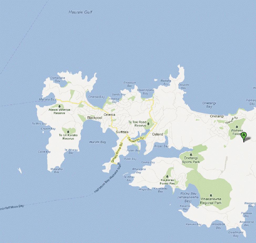
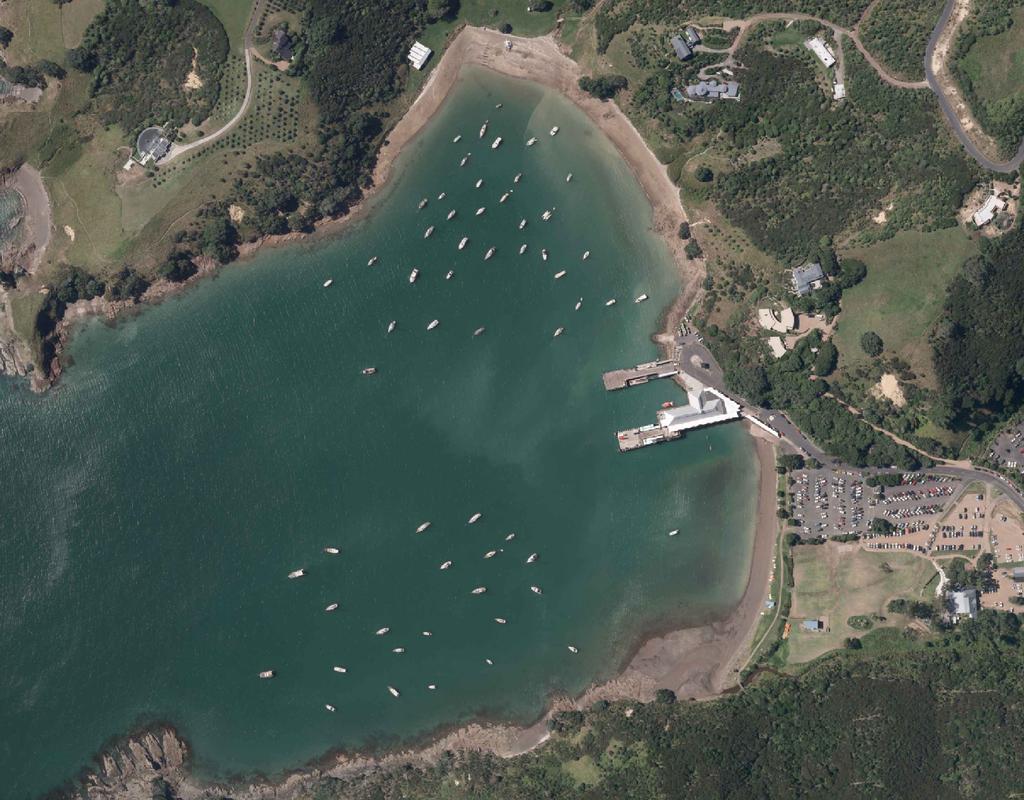
3 Practice Note This evidence is within my area of expertise, except where I state that I rely upon the evidence of other expert information as presented to this hearing. I have not omitted to consider any material facts known to me that might alter or detract from the opinions expressed by me. Scope of Evidence 8. My evidence covers the following matters: A. Marina Location B. Matiatia Site Conditions C. Marina Design including: - General Design Requirements - Wave Height Limit Criteria - Review of Ferry Wake Waves - Marina Wave Protection - Marina Entrance - Marina Berths - Public Facilities - Reclamation - Dredging D. Alternative Locations Review A. Marina Location 9. The proposed marina facilities are located within the North-East portion of Matiatia Bay as depicted on Figure The proposed marina berths are north of the existing wharves to avoid conflict with existing ferry, wharf and boat ramp activities (refer Figure 2). Similarly, the small associated reclamation area is also to the north of the existing wharves and boat ramp facilities. 11. Road access to the site is well established and by sea it is a gateway to the island from Auckland. The site has existing depths suitable for a marina with minimal dredging and is a designated vessel mooring area. Services infrastructure to the Bay already exists. 12. Matiatia has therefore been selected as the preferred site for a marina facility. 2
4 B. Matiatia Site Conditions B(i) Seabed Levels 13. Within the context of a marina proposal, relevant site conditions are summarised as follows: 14. The embayment within the proposed marina berths location has existing seabed levels typically between 2 metres to 4 metres below Chart Datum, with a comparatively small area of shallower water requiring dredging on its eastern extremity. 15. The marina is located sufficiently south to avoid the shallow area to the north (refer Figure 3). B(ii) Wind and Wave Conditions 16. As depicted on the attached Cardno Figure 2.1, wind data from the Manukau Airport highlights a predominance of higher wind strengths from the South-West quadrant for the region. 17. Matiatia Bay is exposed to winds and waves from this direction, albeit with a limited fetch across to Motutapu Island. 18. As detailed in the Cardno wave study, wave heights for various storm events have been determined as follows: Average Recurrence Interval (Years) Wave Height Hs (m) Wave Period Tp (s) Mean Wave Direction ( o TN) MetOcean Solutions two weeks of wind and ferry wave measurements at the site depicted mean significant wave height for wind and ferry wave ambient conditions was 0.1 metres and largest significant wave height at 0.39 metres. Mean periods for these wind waves were within the range of 1.5 seconds to 2.5 seconds. 20. Regular ferry services operate from the terminal just to the south of the marina site. Ferries entering and leaving the bay regularly create wake waves that will propagate to the site. 3
5 21. The largest wake wave measured was metres. The highest events (waves larger than 0.25 metres) typically had wave periods in the range of 4.5 seconds to 9.0 seconds. 22. The mean wake wave height towards the western end of the site was metres and metres at the eastern end. 23. Wake waves were predominantly transverse wake waves (travelling in the same direction as the ferry) from ferries entering Matiatia. B(iii) Tides and Currents 24. Typically, as you go further up a harbour, the tidal range increases. As expected, the Matiatia tidal range is therefore less than Auckland s (by about half a metre). 25. As detailed in the Cardno report, the Tidal Plane at Matiatia Bay is characterised as follows (relative to Chart Datum): MHWS MHWN MSL MLWN MLSW 2.8 metres 2.4 metres 1.6 metres 0.6 metres 0.3 metres 26. Highest Astronomical Tide is predicted at 3.1 metres. There are no significant tidal currents within the bay. 27. Long-term tidal data from Auckland shows that sea level rise to 2050 may be 0.1 metres (excluding recent climate change projections). NIWA and Ministry of Environment (2008) recommend a sea level rise to 2100 of between 0.18m and 0.59m. I consider a 50 year time horizon allowance of 0.4m satisfactory for infrastructure design. B(iv) Infrastructure and Facilities 28. Road and services to the bay and public amenities are already established. There is a significant amount of established car parking. However, convenient additional dedicated marina parking is necessary. 29. There are some 52 moorings within the proposed marina area that will be accommodated within the marina development or relocated. 4
6 30. Extension to the marina site of power and telecommunications will be undertaken. C. Marina Design C(i) General Design Requirements 31. General marina design requirements for safety, usability, navigation, services requirements, marina berths configurations and depth requirements are set out in the relevant Code Guidelines for Design of Marinas AS , which is adhered to for design of this marina proposal. 32. It is of paramount importance to provide a safe all-weather haven for vessels and marina patrons. To this end satisfactory wind wave height limit criteria need to be achieved for predicted storm conditions. For the Matiatia location, satisfactory ferry wake limit criteria also need to be achieved. 33. The following section outlines the determination of those limit criteria. C(ii) Satisfactory Wave Height Limit Criteria 34. For the analysis of any wave protection solutions it is necessary to establish an acceptable set of criteria from which a judgement can be reached on achievement of a satisfactory wave climate. Wind Waves: 35. The determination of a set of (wave height limit) criteria is somewhat subjective, ranging from what is the limit to be reasonably sure a vessel won t get damaged, to what is regarded as ideal for berth users (flat calm). 36. The criteria for acceptable limits in storm conditions has been researched and referenced in appropriate marina design codes. However, extrapolating this data has been seen as potentially problematic or inappropriate, particularly with regard to regular vessel wake situations. 37. The primary point of reference in New Zealand and Australia is the Australian Standard AS3962 Guidelines for Design of Marinas, Table 4.2, Criteria for a Good Wave Climate in Small Craft Harbours. 5
7 TABLE C(ii) CRITERIA FOR A GOOD WAVE CLIMATE IN SMALL CRAFT HARBOURS Direction and peak period of Significant Wave Height (Hs) design harbour wave Wave event exceeded once in 50 years Wave event exceeded once a year Head seas less than 2s Conditions not likely to occur Less than 0.3m wave height during this event Head seas greater than 2s Less than 0.6m wave height Less than 0.3m wave height Oblique seas greater than 2s Less than 0.4m Less than 0.3m wave height Beam seas less than 2s Conditions not likely to occur Less than 0.3m wave height during this event Beam seas greater than 2s Less than 0.25m wave height Less than 0.15m wave height NOTE: For criteria for an excellent wave climate multiply wave height by 0.75, and for a moderate wave climate multiply wave height by For vessels of less than 20m in length, the most severe wave climate should satisfy moderate conditions. For vessels larger than 20m in length, the wave climate may be more severe. 38. The source of the above criteria was a paper presented at a Coastal Engineering Conference in Cape Town in As this is contained within the Code, it is still regarded somewhat as a benchmark and is also quoted within the Matiatia Marina reports. However, although IMC was significantly involved in the formulation of the overall Code, we also recognise the limitations of some criteria. 40. Table C(ii) is oriented towards wind generated wave criteria with reference to 50 year and once a year events and does not specifically address frequent wake wave scenarios. 41. It should also be noted that Table C(ii) specifies Significant Wave Height (Hs). Maximum wave heights can be up to 1.84 Hs as pointed out in the 2011 proposal see the A.J. Raudkivi 3 report. 42. If you wish to justify a wave height as being acceptable within the Code parameters you could then look at an extreme case of multiplying the 0.6m significant wave height for head seas by 1.25 for the moderate wave climate and then by 1.84 to determine a maximum height that could be experienced within a Code Satisfactory marina: 0.6m x 1.25 x 1.84 = 1.38m, which is definitely not acceptable in any marina situation. 3 Raudkivi 2011 Proposal Report 6
8 Wake Waves: 43. By the same token, I do not think it is advisable to try to justify a satisfactory wake wave criteria by picking or multiplying a number from Table C(ii), particularly if you try to apply once a year storm wave criteria to regular daily wake waves. 44. I consider there are four primary criteria that need to be addressed when assessing satisfactory wake criteria. These are user comfort, safety, facility longevity and maintenance. The latter two are very dependent on the detailed design of the chosen marina system so cannot be dealt with in any detail at this stage. 45. As discussed, the choice of acceptable criterion is somewhat subjective, and complaint-based assessment is obviously a primary source for acceptance criteria. Marinas (such as Bayswater in Auckland, marinas on the Brisbane River and around Sydney Harbour) that regularly experience (wake) waves of as low as 150mm, produce complaints. 46. The primary comfort sensitivity for people in boats is roll, pitch, surge and sway that can easily fall within the typical sensitive frequencies of marina sized vessel motion. Experience suggests that any waves within these typical vessel motion frequencies should be avoided (refer Attachment 1). 47. As evidenced by the Code criteria, head seas are far less problematic and wave heights around twice that of the beam seas are required to be categorised as outside the required comfort criteria. 48. Safety typically equates to situations of personal instability onboard due to vessel rolling and pitching motion, transfer from vessel to dock and potential injury from limbs between vessel and dock. Instability criteria are typically towards the upper bounds of the comfort criteria. 49. The US Navy has limits on the maximum amount of acceleration and roll (or pitch) acceptable on the bridges of vessels. Maximum horizontal acceleration: 0.2g Maximum vertical acceleration: 0.4g Maximum roll: 8 degrees Maximum pitch: 3 degrees 7
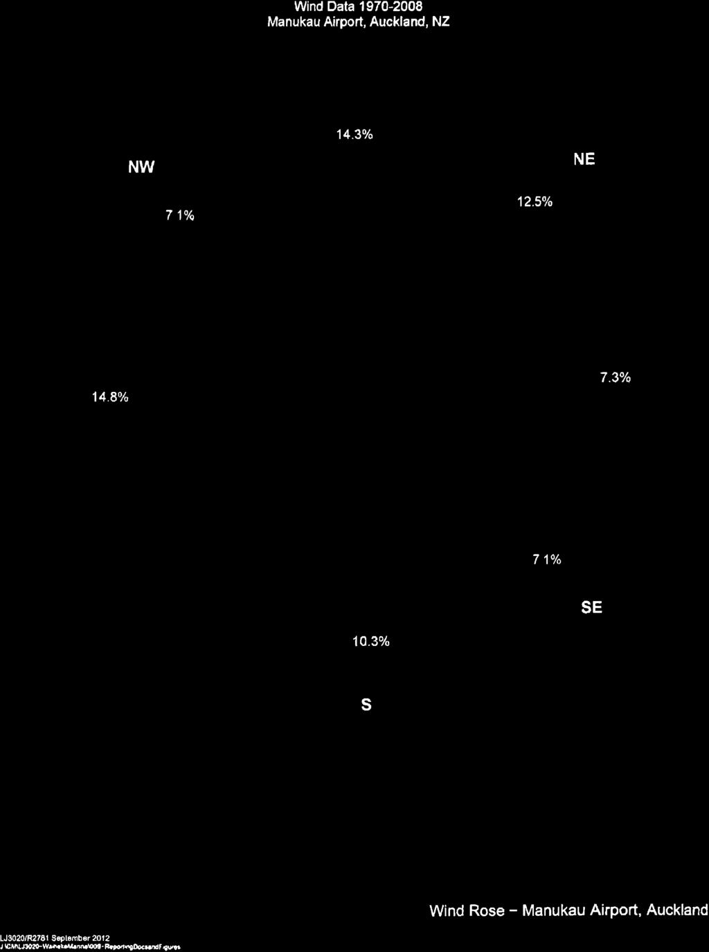
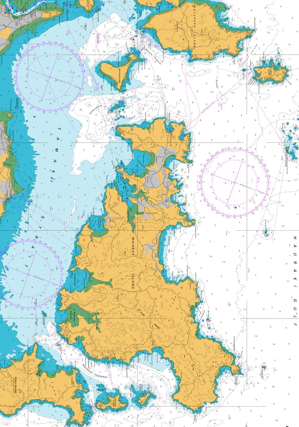
9 50. These limits reflect survival of equipment and a well prepared crew so are considered too severe for the casual environment of a marina. 51. Research in the Netherlands reviewed stability criterion for response of the body to acceleration for various body orientations. A surprise stability coefficient was recommended at 55% of maximum acceleration. Assuming an initial casual stance, a surprised or disabled body will topple if the acceleration exceeds 0.09g (0.9m/s 2 ). 52. Comfort criteria research for tall building sway found that walking becomes difficult when building accelerations exceed 0.04g (0.4m/s 2 ). 53. This is consistent with allowable/tolerable accelerations computed for docks and the premise that safety criteria are typically twice that of comfort limit criteria. 54. Having established some benchmark criteria, the challenge is then to translate this to a reasonable form of wave limit criteria (to cross check against the all important complaint based criteria). 55. The Australian Marine and Offshore Group undertook a study to review acceptability of pontoon movement. Two pontoons were modelled, Type A, being a 9m x 3m with Ai having a 6 tonne displacement and Aii 12.7 tonnes and Type B, a 12m x 4m pontoon with Bi having a 9.9 tonne displacement and Bii 19.8 tonnes. Results are tabulated in Attachment The B type pontoon is considered to reasonably resemble a 40 to 45 foot power boat and the A type a 30 to 36 foot power boat. As can be seen from the results, at Hs = 0.1m the horizontal accelerations for head seas have gone above the abovementioned limit criteria. 57. Attachment 1 depicts results from a Canadian Government Report Study to Determine Acceptable Wave Climate in Small Craft Harbours. As can be seen from the response graphs, resonance for pitch, heave and roll for wave periods between 1 to 3 seconds is particularly problematic with sway dominating at longer periods. Horizontal accelerations due to sway in longer periods therefore needs due consideration also. 58. It is noted that roll criteria for horizontal acceleration of a body standing on a floating pontoon is not included within the pontoon and vessel response results. 8
10 59. Analysis of roll for various wave heights and periods has been carried out with results as follows: Wave Period Wave Height Body Acceleration * 3 seconds 0.15m 0.04g 3 seconds 0.3m 0.08g 5 seconds 0.15m 0.005g 5 seconds 0.3m 0.001g 7 seconds 0.15m g 7 seconds 0.3m g * Body acceleration calculated at body centre of gravity 2.0m above still water level. 60. It is noted that the shorter 3 second wave period results for 0.3m wave height and 0.15m wave height roughly coincides with the earlier derived casual stance surprised or disabled body topple acceleration of 0.09g and 0.04g for the comfort limit. This also correlates with Marina Code Good once-a-year wave climate criteria for the 0.3m and marina complaint feedback for the 0.15m. 61. The conclusion to the above research and analysis, considering complaints at 0.15m, pontoon dynamic results for horizontal acceleration limits at 0.1m and body topple acceleration comfort limit at 0.15m, is that regular vessel wake limits of less than 0.15m must be achieved and that 0.1m is a satisfactory outcome objective. 62. Similarly the wind wave maximum of 0.3m must also be achieved for a satisfactory outcome. C(iii) Review of Ferry Wake Results General: 63. I note that the MetOcean report measurements are for current ferry vessels. Although this provides a good data source for appropriate wave protection strategies review, the question is raised as to flexibility to accommodate future vessel characteristics. 64. Studies (and problems) throughout the world have clearly identified that catamaran ferries cause the most trouble. The critical wakes recorded in this case are from catamaran ferries so any future change to more mono-hulls would not increase wave protection requirements. 9
11 Wake Results: 65. The largest catamaran ferry, as expected, created the largest measured waves. As outlined in the MetOcean report, the largest wake heights were 307mm to 344mm. The corresponding wake period of the highest events is typically in the range of 4.5 to 9.0 seconds. 66. Catamaran ferry wake results, for a situation where they are slowing to arrive at a terminal, are dominated by their transverse waves which are orientated more perpendicular to the direction of travel (refer Figure 2.1 of the MetOcean report and photos 1 to 6 in Attachment 3 from the Ade Consultants letter of 10 June 2011 for the 2011 proposal). 67. Mono-hull vessels will display the same broad characteristics, but the persistence of the transverse wave (in the direction of ferry travel) by catamarans is more pronounced. 68. Although the results do not provide wave direction data, experience suggests that the wake wave direction will be roughly in the direction of ferry travel to the Matiatia Ferry Terminal (refer Attachment 3, Photo 6). 69. The statement in the 2011 proposal Christian 4 report that the wake waves are more likely to be beam-on to marina vessels is not therefore valid. However, the comment that the long wave length of these waves will pass through the floating attenuator almost un-attenuated is valid. Wind Generated Waves: 70. As discussed in the Cardno report, the storm wind generated waves are of much lesser wave length but have a greater height. During the two week wave data collection period, significant westerly sector wind wave events were recorded which suggests the ambient wave conditions are relatively mild but extreme event wave height protection is required. 71. As tabulated in Section B(ii), the One Year ARI storm wave height is 0.56 metres and 50 year is 0.76 metres. 72. Wind wave energy combined with regular wake waves on marina comfort, safety and marina structure longevity and maintenance is far more concerning 4 C D Christian 2011 Proposal Report 10
12 when the embayment exposure direction is also from this direction, which is the case at Matiatia. C(iv) Marina Wave Protection 73. As outlined in the Cardno wave study report, the marina primarily requires protection from West through to South-West waves. Particular attention needs to be given to marina protection considering that the predominant strong winds come from this direction as does the potentially troublesome regular ferry wake waves. 74. There are three basic options for providing such protection, namely rock breakwaters, panel breakwaters or floating attenuator structures. 75. From previous analysis and observations in Auckland, 30 plus knots from the W- SW is not uncommon (436 observations from 1970 to 2008). The 1970 to 2008 records analysis determined that a 1-year return period Westerly 10 minute wind speed was m/s (34.9 knots). 76. The use of a wave attenuator design, which allows a significant amount of energy through, should therefore be approached with caution, considering comfort, potential marina structures maintenance and longevity. 77. The fact that ferry wakes have been measured regularly over 0.3m within a two week period (MetOcean s measurements) is also cause for concern when these waves will not be significantly reduced by a wave attenuator design and research suggests that they should be kept to well under half this value. 78. In my opinion the required wave height objective of 0.1m within the marina for regular ferry wake waves and absolute maximum of 0.15m cannot be achieved for longer period transverse waves using floating wave attenuator structures along the South-west perimeter. 79. MetOcean highest wake heights measurements depict wake periods typically in the range of 4.5 to 9 seconds. Largest wake heights were 307mm to 344mm. 80. For an 0.3m transverse wake with a 4.5 second period the required width of a double skirted floating attenuator structure would need to be in the order of 9m to achieve a 0.1m wave height on the lee side of the structure. For wave period of 7 seconds (the approximate mean of the abovementioned range) the 11
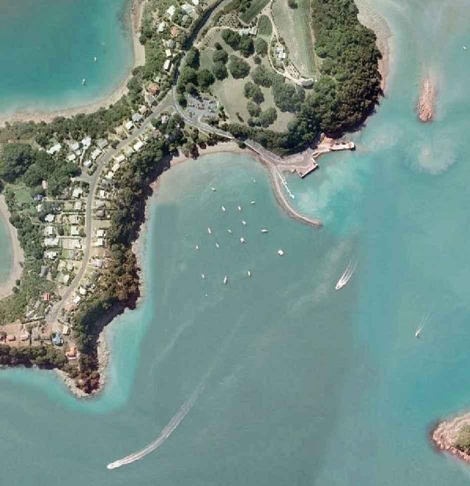
13 attenuator width would need to be over twice this width. This is clearly impractical and this is the reason attenuators are not considered a viable solution with wave periods significantly above 4 seconds. 81. A panel breakwater or rock breakwater therefore needs to be considered. Either of these solutions, if acceptable from a planning, aesthetic and environmental perspective, are satisfactory in terms of being able to achieve the necessary marina wind/wave climate. C(v) Breakwater Protection Solutions 82. As discussed above and within the Cardno report, the main exposure for wind and wake waves is from the South-west. Satisfactory wave protection requires either fixed panel or rock breakwaters for this direction. Fixed Panel Option: 83. We have determined a (vertical) fixed panel option would need to go from the sea bed to around 4 metres above mean high water to ensure there was significant wave energy cut-off, no significant wave crest overtopping in severe storms with high surge levels and allowance for potential sea level rise. 84. This would obviously be a substantial visual issue. It is also a comparatively high cost structure with potentially high longer-term maintenance and replacement costs. 85. This long vertical panel structure would also create a high degree of reflected wave energy back into the bay with a potentially very confused sea state in front of the marina. Rock Breakwater Option: 86. With less wave build-up against a rock slope, the rock breakwater provides a lower structure top height solution. I have estimated that it can be as much as 1 meter lower than the panel option. 87. It is also more conducive to providing public/recreational access with rock slope to the water rather than a vertical wall. A footpath with berms each side can be provided (as proposed) rather than a safety barriered platform on top of the vertical wall for the panel option. It should also be noted that if someone were 12
14 to fall into the water, they cannot be readily retrieved with a vertical wall scenario. 88. In light of the above, and the understandable longevity and low maintenance of rock structures, the rock breakwater option has been adopted and modelled by Cardno. A satisfactory wave climate to all parts of the marina is achieved with the double breakwater option as depicted in Figure 3. Floating Attenuators: 89. As discussed previously, a floating wave attenuator is not a satisfactory solution for the long period transverse ferry wake waves which will regularly approach the site from the South-west. However, as with the 2011 proposal, a floating attenuator structure is appropriate for providing wave energy protection from the South. 90. This southern fetch across the bay to the site is approximately 300 metres. Potential wind generated waves from this direction would be in the order of 0.3m with an associated wave period less than 1.5 seconds. 91. The proposed 4 metre wide Southern Access Pier floating attenuator structure (refer Figures 3 and 5) has a transmission coefficient of approximately 0.1 for such short period waves and therefore easily achieves the marina wave climate criteria. 92. The diverging bow wake waves from ferries approaching the wharf (at slow subcritical speeds as they are preparing to berth) will be low height (less than 0.2m) with a typical angle of approach of around 35 degrees. The transmission coefficient for such waves would be in the order of 0.4 resulting in a wave height of less then 0.1m on the marina berths side of the floating attenuator. C(vi) Marina Entrance The 2011 proposal configured the marina entrance at the Southwest corner. 93. Concerns were raised with respect to ferry activity conflicts. The entry has now been configured to the North-west to minimise such conflict. 94. To avoid entrance channel capital and maintenance dredging and provide a satisfactory navigable entrance width, the primary breakwater finishes approximately 75 metres from the shore. However, to achieve the satisfactory 13
15 marina wave climate criteria, a secondary breakwater, as depicted on Figure 3 is required. C(vii) Marina Berths 95. As depicted on Figure 4, the marina berths are orientated in a south-west orientation in keeping with the bay s exposure and predominant strong wind direction. 96. Berths are configured with fairways based on 1.75 times the berth length as recommended by the Marina Code and in keeping with a good international standard facility. 97. Pier (A, B, C and D) walkways are configured at a width of 2 metres and the Southern Access Pier at 4 metres width. This South Access Pier walkway has a double skirt underwater configuration (refer Figure 5) to provide attenuation of wave energy that diffracts around the southern end of the primary breakwater and locally generated wind waves and boat wakes approaching from the south across the bay. 98. Marina berths services will comprise power and low-level lighting via services pedestals. Firefighting services will also be included. A sewage pump out facility will be available on the floating pontoon to the south of the marina. Power outlets are proposed to be metered to deter over-use. 99. It is proposed that the floating marina system would be a high mass, low maintenance, concrete deck system in keeping with the philosophy of constructing a high international standard facility The mix of berth sizes has been proposed in keeping with current marina market demand and trends and expressions of interest received during feedback for the proposal The proposed size mix is depicted on Figure 3 with 160 berths ranging from 10.5 metres to 20 metres with the ability to accommodate vessels above 20 metres, if required, on the ends of Piers B and C A floating marina office is located at the start of the marina walkway. This office has been configured on the basis of keeping it to an efficient minimum area requirement. 14
16 C(viii) Public Facilities 103. As depicted on Figure 4, public access continuity is provided around the proposed reclamation (and around the deck option) which includes a boardwalk from the north to the footpath around the parking area and the viewing platform Public access is provided along the primary breakwater which includes a footpath and viewing platform at its southern end. The Southern Access Pier is also available to the public, which includes a viewing platform at its western end and gangway access to the breakwater Dinghy racks are included near the start of the Pier adjacent to the marina office with a berth for the Coast Guard on the pier s southern side. The new floating dinghy racks will be similar to those in place at south-west end of Westhaven Marina (Pier X). A total of 17 rack spaces are proposed for the pile moorings Seventeen pile moorings have been included within the proposal as part of implementing suitable swing mooring relocation arrangements. The proposed vessel size mix for these are 2x8m, 6x10.5m, 7x12m, 1x14m and 1x15m with water depths between 1m and 2m below lowest tide (refer Figure 3). They are within the protected waters of the marina and conveniently located for access from the marina or from the adjacent beach area The existing four mooring holder and two disabled parking spaces have been retained in the area adjacent to the existing boat ramp. C(ix) Reclamation 108. As discussed previously, a small reclamation is proposed adjacent to the marina berths Locating the marina management office on a floating structure within the marina is consistent with the philosophy of keeping the reclamation to an unobtrusive minimum The proposed reclamation area seaward of Mean High Water Springs is approximately 0.3 hectares. 15
17 111. As discussed in Section C(vi), public access is maintained around this area via a footpath around its seaward perimeter and access promoted by inclusion of a boardwalk connection to the north and incorporation of a viewing platform within the north-west corner The area so created is sized to provide 55 car parking spaces including shortterm and long-term zones The reclamation finished level is +4.5m above chart datum. With an allowance of 0.4m for sea level rise and 0.5m for storm effects (refer Christian report), the extreme water level for MHWS m = 3.7m is still well below the +4.5m proposed pavement level. C(x) Dredging 114. The marina has been sized, located and configured to reasonably minimise the amount of dredging without pushing the marina too far off-shore. Whilst locating the marina and its entry sufficiently north to avoid potential conflict with ferry activities, the northern extent has been limited to provide all-tide navigable access to Piers B, C and D without the need to dredge the bay on the northern side The smallest berths with least navigation depth requirements have been located within the near-shore pier (Pier A) to also minimise dredging requirements In accordance with the above, the proposed marina dredging volume is 5,023 cubic metres with a dredge seaward slope profile from -2m to -2.5m to minimise siltation Water depth requirements as outlined in the marina code (AS3962) are as follows: Vessel Size Draft Keel Clearance Design Depth 10.5m 1.8m 0.3m 2.1m 12m 2.0m 0.3m 2.3m 13.5m 2.2m 0.3m 2.5m 14m 2.3m 0.3m 2.6m 15m 2.5m 0.3m 2.8m 16m 2.6m 0.3m 2.9m 20m 2.9m 0.3m 3.2m 16
18 118. As depicted on Figure 6 the only dredging required to achieve satisfactory alltide navigation depths is within Pier A and the associated adjacent navigation channel Any smaller sized vessels that could be accommodated within Pier A that have abnormally deep drafts requiring deeper water would be allocated to a larger berth further seaward, thus keeping the proposed dredge depths to a minimum As depicted in Figure 3 the remainder of the marina has existing depths typically between 3m to 4m below chart datum, which is more than sufficient for their vessel/berth size category As detailed in the 2011 Raudkivi report, expected siltation inputs are so low that their overall effect is less than the predicted sea level rise. With such low siltation potential the effect of the breakwaters on such insignificant siltation is correspondingly also not going to have any significant effects. C (xi) Suspended Car Park Deck Option 122. WML has been given advice that there may be a planning requirement to avoid reclamation. IMC has therefore been instructed to review this Figure 9 depicts a suspended car park deck option which is based on the same car park layout as for the reclamation proposal. The suspended deck is designed as a precast reinforced concrete deck to minimise over water site works and is supported by driven reinforced concrete piles The viewing platform is proposed as a pile supported timber deck structure. D. Alternative Locations Review 125. Having been advised of submissions suggesting a number of alternative marina locations, a review of these sites has been carried out. The alternative sites review included an inspection of each site by boat in March These alternative sites are (refer Figure 7): Owhanake Church Bay Rocky Bay Huruhi Bay Putiki Bay Kennedy Point 17
19 D(i) Owhanake 127. This site has significant exposure to wave energy (including ocean swells) from the North-West As such, extensive breakwaters would be required across the bay, which would significantly close off the upper portion of the bay. D(ii) Church Bay 129. Notwithstanding there is no public road access, this site has a very wide window of wave energy exposure from the South through to the North-East. As such, extensive breakwater protection would be required. D(ii) Rocky Bay 130. Rocky Bay is exposed to the South-West (predominant) strong wind direction. It also has extensive shallows and numerous navigational obstructions when entering the bay Extensive breakwaters would be required and the practicality of constructing these on the expected soft mud sea bed is questionable. D(iv) Huruhi 132. Again, this location has exposure to the South-West requiring significant breakwater protection and questionable breakwater construction practicality due to expected soft seabed materials. D(v) Putiki Bay 133. This bay has extensive shallows requiring extensive dredging to achieve satisfactory all-tide water depths. It is also expected that the dredging requirement would create an on-going maintenance dredging issue As with the other South-West facing locations, extensive breakwaters would be required and soft sea-bed materials would make breakwater construction practicality questionable. 18
20 D(vi) Kennedy Point 135. This site is less exposed to the South-Westerlies but still would require rock breakwater protection works. D(vii) Alternative Sites Conclusion 136. On review of the sites, Kennedy Point was the only one considered worthy of a further review. Figure 8 depicts an indicative concept of similar size to that proposed for Matiatia Although not as directly exposed to the South-West as most other sites reviewed, there are significant breakwater construction requirements and associated reclamation to address access and parking demand issues. It is also expected that soft seabed materials are likely to hinder breakwater construction practicalities All of the above suggests that Matiatia is a more favourable solution. John Leman Date: 30 April
21
22
23
24
25
26
27
28
29
30
31 RESERVE HISTORIC

32 RESERVE HISTORIC
33
34 HISTORIC RESERVE
35


36
37
Implications of proposed Whanganui Port and lower Whanganui River dredging
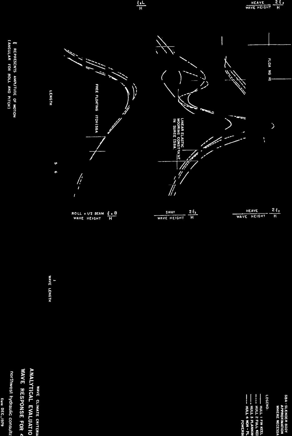
 PO Box 637 Wanganui 4540 Attention: Rowan McGregor Dear Rowan 1 Summary We understand that it has been proposed to bring large vessels into the Port at Whanganui requiring the excavation of a channel up
Shoreline Response to an Offshore Wave Screen, Blairgowrie Safe Boat Harbour, Victoria, Australia
 Shoreline Response to an Offshore Wave Screen, Blairgowrie Safe Boat Harbour, Victoria, Australia T.R. Atkins and R. Mocke Maritime Group, Sinclair Knight Merz, P.O. Box H615, Perth 6001, Australia ABSTRACT
DUKC DYNAMIC UNDER KEEL CLEARANCE
 DUKC DYNAMIC UNDER KEEL CLEARANCE Information Booklet Prepared in association with Marine Services Department 10/10/2005 Dynamic Under Keel Clearance (DUKC) integrates real time measurement of tides and
Technical Brief - Wave Uprush Analysis Island Harbour Club, Gananoque, Ontario
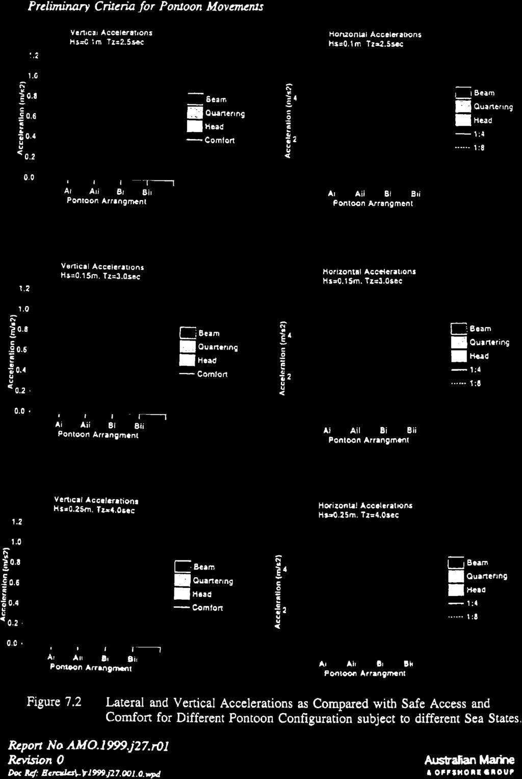
 Technical Brief - Wave Uprush Analysis RIGGS ENGINEERING LTD. 1240 Commissioners Road West Suite 205 London, Ontario N6K 1C7 October 31, 2014 Table of Contents Section Page Table of Contents... i List
Before the Environment Court at Auckland
 Before the Environment Court at Auckland ENV-2013-AKL-000174 In the Matter of the Resource Management Act 1991 And In the Matter of a Notice of Motion under Section 87G requesting the granting of resource
PORTS AUSTRALIA. PRINCIPLES FOR GATHERING AND PROCESSING HYDROGRAPHIC INFORMATION IN AUSTRALIAN PORTS (Version 1.5 November 2012)
") PORTS AUSTRALIA PRINCIPLES FOR GATHERING AND PROCESSING HYDROGRAPHIC INFORMATION IN AUSTRALIAN PORTS (Version 1.5 November 2012) PREFACE These Principles have been prepared by the Hydrographic Surveyors
PORTS AUSTRALIA PRINCIPLES FOR GATHERING AND PROCESSING HYDROGRAPHIC INFORMATION IN AUSTRALIAN PORTS (Version 1.5 November 2012) PREFACE These Principles have been prepared by the Hydrographic Surveyors
The development of the historical harbour of Paphos, Cyprus H.J. van Wijhe*, M. Meletiou^ Division, P.O. Box 152, 8300 AD Emmeloord, The Netherlands
 The development of the historical harbour of Paphos, Cyprus H.J. van Wijhe*, M. Meletiou^ Division, P.O. Box 152, 8300 AD Emmeloord, The Netherlands Abstract The harbour of Paphos originates from ancient
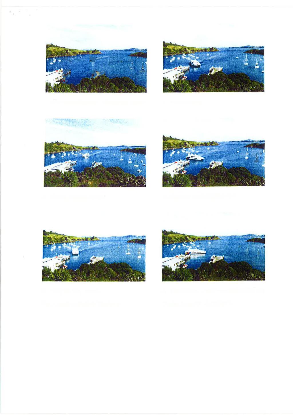
Preventing Damage to Harbour Facilities and. Ship Handling in Harbours PART 2 INDEX
 Preventing Damage to Harbour Facilities and Ship Handling in Harbours PART 2 INDEX 1 Vessel handling is based on the basic knowledge that a vessel floats in the water and returns to its original position
# Post Consultation and Submissions Resource Consent Conditions for Surfing Impact Mitigation August 2016
 # Post Consultation and Submissions Resource Consent Conditions for Surfing Impact Mitigation August 2016 Surf Mitigation Management Plan 1 1 Not less than 6 months prior to the commencement of the construction
ROYAL VANCOUVER YACHT CLUB
 ROYAL VANCOUVER YACHT CLUB PROPOSED EXPANSION PROJECT NAVIGATION CHANNEL DESIGN COAL HARBOUR Prepared for: Royal Vancouver Yacht Club Prepared by: Typlan Consulting Ltd. March 2016 Page 1 of 17 March 23,
WOODFIBRE LNG VESSEL WAKE ASSESSMENT
 Woodfibre LNG Limited WOODFIBRE LNG VESSEL WAKE ASSESSMENT Introduction Woodfibre LNG Limited (WLNG) intends to build a new LNG export terminal at Woodfibre, Howe Sound, British Columbia. WLNG has engaged
APPENDIX D-2. Sea Level Rise Technical Memo
 APPENDIX D-2 Sea Level Rise Technical Memo 2185 N. California Blvd., Suite 500 Walnut Creek, CA 94596 (925) 944-5411 Fax: (925) 944-4732 www.moffattnichol.com DRAFT MEMORANDUM To: From: Neil Nichols,
Port Sections Guide Section 01
 s Guide 01 Cow Bay Marina Date 10/1/2016 Position (lat / lon) Minimum controlled water depth Chart datum Range of water densities Tidal range alongside Bottom type Dredging regime Distance pilot station
Hydrographic Surveying Methods, Applications and Uses
 Definition: Hydrographic Surveying Methods, Applications and Uses It is the branch of surveying which deals with any body of still or running water such as a lake, harbor, stream or river. Hydrographic
HARBOUR SEDIMENTATION - COMPARISON WITH MODEL
 HARBOUR SEDIMENTATION - COMPARISON WITH MODEL ABSTRACT A mobile-bed model study of Pointe Sapin Harbour, in the Gulf of St. Lawrence, resulted in construction of a detached breakwater and sand trap to
Technical Brief - Wave Uprush Analysis 129 South Street, Gananoque
 Technical Brief - Wave Uprush Analysis 129 South Street, Gananoque RIGGS ENGINEERING LTD. 1240 Commissioners Road West Suite 205 London, Ontario N6K 1C7 June 12, 2013 Table of Contents Section Page Table
BILLY BISHOP TORONTO CITY AIRPORT PRELIMINARY RUNWAY DESIGN COASTAL ENGINEERING STUDY
 Bâtiment Infrastructures municipales Transport Industriel Énergie Environnement BILLY BISHOP TORONTO CITY AIRPORT PRELIMINARY RUNWAY DESIGN COASTAL ENGINEERING STUDY N. Guillemette 1, C. Glodowski 1, P.
INTRODUCTION TO COASTAL ENGINEERING
 The University of the West Indies Organization of American States PROFESSIONAL DEVELOPMENT PROGRAMME: COASTAL INFRASTRUCTURE DESIGN, CONSTRUCTION AND MAINTENANCE A COURSE IN COASTAL DEFENSE SYSTEMS I CHAPTER
F4. Coastal Mooring Zone and moorings outside the Coastal Mooring Zone
 F4. Coastal Mooring Zone and moorings outside the Coastal Mooring Zone F4.1. Zone description This section addresses the provisions relating to moorings in the Coastal Mooring Zone and those outside the
Crew Transfer Vessel (CTV) Performance Benchmarking. Presented by Stephen Phillips of Seaspeed Marine Consulting Ltd
 Performance Benchmarking. Presented by Stephen Phillips of Seaspeed Marine Consulting Ltd") Crew Transfer Vessel (CTV) Performance Benchmarking Presented by Stephen Phillips of Seaspeed Marine Consulting Ltd BACKGROUND - CT OWA : The Carbon Trust Offshore Wind Accelerator (OWA) brings together
Crew Transfer Vessel (CTV) Performance Benchmarking Presented by Stephen Phillips of Seaspeed Marine Consulting Ltd BACKGROUND - CT OWA : The Carbon Trust Offshore Wind Accelerator (OWA) brings together
Planning of Major Recreational Boating Facilities at Shell Cove Boat Harbour
 Planning of Major Recreational Boating Facilities at Shell Cove Boat Harbour B Morgan 1, Deborah Lam 1, Glenn Colquhoun 2 1 Advisian, Sydney, NSW 2 Frasers Property Australia, Shell Cove, NSW Abstract
13. TIDES Tidal waters
 Water levels vary in tidal and non-tidal waters: sailors should be aware that the depths shown on the charts do not always represent the actual amount of water under the boat. 13.1 Tidal waters In tidal
Transport Infrastructure Act 1994 Gladstone Ports Corporation. Port Notice 04/17 LNG Vessel Operating Parameters
 Transport Infrastructure Act 1994 Gladstone Ports Corporation Port Notice 04/17 LNG Vessel Operating Parameters 1. These operating parameters have been developed based on navigation simulations with LNG
Part 9 Specific Land Uses - Foreshore & Waterway Development
 7 FORESHORE AND WATERWAY DEVELOPMENT This section applies to the following development uses proposed within the foreshore area (defined by LM LEP 2014), and contains Council s specific requirements for
BWS ONLINE FORECASTING BERTH OPERATING SAFETY. Matthew R. O Halloran, Daphne Choong
 BWS ONLINE FORECASTING BERTH OPERATING SAFETY Matthew R. O Halloran, Daphne Choong OMC International Pty Ltd, 2/2 Walmer St, Abbotsford, Vic 3067, Australia matthew@omc-international.com.au daphne@omc-international.com.au
NAUTICAL TERMINOLOGY
 It s important to have a basic understanding of common nautical terms associated with the parts, positions and directions of your vessel. Knowing these terms will make it easier to communicate with people
Visiting Lake Macquarie
 Visiting Lake Macquarie Lake Macquarie is the largest coastal salt water lake in Australia and is a prime boating destination for both small and large vessels. Many sailing regattas and fishing activities
Innovative and Robust Design. With Full Extension of Offshore Engineering and Design Experiences.
 Innovative and Robust Design by VL Offshore With Full Extension of Offshore Engineering and Design Experiences www.vloffshore.com Y Wind Semi Designed by VL Offshore The Y Wind Semi platform (foundation)
FULL SCALE MEASUREMENT OF DYNAMIC SHIP MOTIONS AND SQUAT
 FULL SCALE MEASUREMENT OF DYNAMIC SHIP MOTIONS AND SQUAT Mr. Gary Rolph Chief Hydrographic Surveyor Port of Brisbane Corporation Mr. Peter Rumball Surveyor Port of Brisbane Corporation Dr. Terry O'Brien
Request Number IR1-12: Flow Passage. Information Request
 Request Number IR1-12: Flow Passage Information Request Provide additional information about the 100 metre flow passage channel scenario between the Westshore Terminals and the proposed Project terminal
Pier 8 Wave Overtopping Analysis (65 Guise Street East) Our File:
 Our File:") Shoreplan Engineering Limited 55 Eglinton Avenue E., Suite 800 Toronto, ON Canada M4P 1G8 T) 416.487.4756 F) 416.487.5129 E) mail@shoreplan.com March 31, 2016 Mr. Ed English Senior Project Manager Waterfront
Shoreplan Engineering Limited 55 Eglinton Avenue E., Suite 800 Toronto, ON Canada M4P 1G8 T) 416.487.4756 F) 416.487.5129 E) mail@shoreplan.com March 31, 2016 Mr. Ed English Senior Project Manager Waterfront
APPENDIX G WEATHER DATA SELECTED EXTRACTS FROM ENVIRONMENTAL DATA FOR BCFS VESSEL REPLACEMENT PROGRAM DRAFT REPORT
 APPENDIX G WEATHER DATA SELECTED EXTRACTS FROM ENVIRONMENTAL DATA FOR BCFS VESSEL REPLACEMENT PROGRAM DRAFT REPORT Prepared for: B.C. Ferries Services Inc. Prepared by: George Roddan, P.Eng. Roddan Engineering
Currents measurements in the coast of Montevideo, Uruguay
 Currents measurements in the coast of Montevideo, Uruguay M. Fossati, D. Bellón, E. Lorenzo & I. Piedra-Cueva Fluid Mechanics and Environmental Engineering Institute (IMFIA), School of Engineering, Research
REVISED SILT CURTAIN DEPLOYMENT PLAN
 Contract No.: HY/2009/11 Central Wanchai Bypass, North Point Reclamation REVISED SILT CURTAIN DEPLOYMENT PLAN Name Prepared by: China Harbour Engineering Co., Ltd. China Road and Bridge Corporation Joint
Number Details Action
 Minutes Present: Gosford City Council, RHDHV & Public Stakeholders. Apologies: From: Karen O'Mara & James Donald Date: Wednesday, 11 May 2016 Location: Gosford Sailing Club Copy: Our reference: M&APA1337M002F01
Figure 4, Photo mosaic taken on February 14 about an hour before sunset near low tide.
 The Impact on Great South Bay of the Breach at Old Inlet Charles N. Flagg and Roger Flood School of Marine and Atmospheric Sciences, Stony Brook University Since the last report was issued on January 31
Surf Survey Summary Report
 Port Otago Limited 15 Beach Street Port Chalmers Surf Survey Summary Report August 13-September 1 Leigh McKenzie Summary of Surf Locations of Interest Port Otago Ltd is undertaking monitoring of changes
A New Strategy for Harbor Planning and Design
 A New Strategy for Harbor Planning and Design Xiuying Xing, Ph.D Research Associate Sonny Astani Department of Civil and Environmental Engineering University of Southern California Los Angeles, CA 90089-2531
Task 16: Impact on Lummi Cultural Properties
 Gateway Pacific Terminal Vessel Traffic and Risk Assessment Study Task 16: Impact on Lummi Cultural Properties Prepared for Pacific International Terminals, Inc. Prepared by The Glosten Associates, Inc.
Dynamic Stability of Ships in Waves
 Gourlay, T.P. & Lilienthal, T. 2002 Dynamic stability of ships in waves. Proc. Pacific 2002 International Maritime Conference, Sydney, Jan 2002. ABSTRACT Dynamic Stability of Ships in Waves Tim Gourlay
Only launch your boat once you have a clear understanding of the most up-to-date weather forecast.
 Weather and Tides Observing the Weather Only launch your boat once you have a clear understanding of the most up-to-date weather forecast. Start with television and newspaper weather map reports; they
Chapter 10 Lecture Outline. The Restless Oceans
 Chapter 10 Lecture Outline The Restless Oceans Focus Question 10.1 How does the Coriolis effect influence ocean currents? The Ocean s Surface Circulation Ocean currents Masses of water that flow from one
APPENDIX 11 WIND EFFECTS ASSESSMENT
 APPENDIX 11 WIND EFFECTS ASSESSMENT Summerset Villages (Lower Hutt) Ltd District Plan Change Request Prepared by Urban Perspectives Ltd 17 September 2014 341 49 342 Opus Research Report 14-529D84.00 Wind
INCREASE OPERATING DAYS ENHANCE DECK SAFETY AND SPEED MINIMIZE SEA SICKNESS HEAVY DUTY GYROSTABILIZERS FOR COMMERCIAL & DEFENCE APPLICATIONS
 LESS MOTION MORE OCEAN HEAVY DUTY GYROSTABILIZERS FOR COMMERCIAL & DEFENCE APPLICATIONS INCREASE OPERATING DAYS ENHANCE DECK SAFETY AND SPEED MINIMIZE SEA SICKNESS 2 VEEM Gyro DEFENCE Image courtesy of
Available online at ScienceDirect. Procedia Engineering 116 (2015 )
") Available online at www.sciencedirect.com ScienceDirect Procedia Engineering 116 (2015 ) 320 325 8th International Conference on Asian and Pacific Coasts (APAC 2015) Department of Ocean Engineering, IIT
Available online at www.sciencedirect.com ScienceDirect Procedia Engineering 116 (2015 ) 320 325 8th International Conference on Asian and Pacific Coasts (APAC 2015) Department of Ocean Engineering, IIT
Designing a Harbor Entrance to Defeat Swell Wave Agitation. FAX (506) ; 2
 ; 2") Designing a Harbor Entrance to Defeat Swell Wave Agitation Mauricio Wesson, MSc. PE 1 and Jack C. Cox, PE, DPE, DCE, DNE 2 1 Watermark, La Sabana, San Jose, Costa Rica; PH (506) 2220-1198; FAX (506) 2290
Designing a Harbor Entrance to Defeat Swell Wave Agitation Mauricio Wesson, MSc. PE 1 and Jack C. Cox, PE, DPE, DCE, DNE 2 1 Watermark, La Sabana, San Jose, Costa Rica; PH (506) 2220-1198; FAX (506) 2290
HARBOR INFRASTRUCTURE INVENTORIES Marquette Harbor, Michigan
 HARBOR INFRASTRUCTURE INVENTORIES Marquette Harbor, Michigan Harbor Location: Marquette Harbor is located in Marquette Bay on the south shore of Lake Superior, 160 miles west of Sault Ste. Marie, MI and
Coastal Inundation. An Overview for TCDC
 Coastal Inundation An Overview for TCDC Rick Liefting Team Leader Regional Hazards and Environmental Compliance Integrated Catchment Management Waikato Regional Council Photo: Sugar Loaf Wharf, Coromandel.
Deepwater Floating Production Systems An Overview
 Deepwater Floating Production Systems An Overview Introduction In addition to the mono hull, three floating structure designs Tension leg Platform (TLP), Semisubmersible (Semi), and Truss Spar have been
CITY OF NEWPORT BEACH HARBOR COMMISSION STAFF REPORT
 CITY OF NEWPORT BEACH HARBOR COMMISSION STAFF REPORT Agenda Item No. 2 TO: FROM: SUBJECT: HARBOR COMMISSION Harbor Resources Division (City Manager's Office) Chris Miller, Harbor Resources Supervisor,
Coastal Engineering Technical Note
 Coastal Engineering Technical Note BAFFLED BREAKWATER FOR LIMITED FETCH SITES CETN III-45.(12/91) PURPOSE: To describe the Spud Point Marina breakwater, an innovative baffledtype breakwater designed to
Forth Ports Limited. Ruling Depths & Under Keel Clearances
 Forth Ports Limited - Forth Vessels are scheduled into / out of ports on the Forth & Tay in accordance with the under keel clearance criteria specified in this section of the Marine Guidelines & Port Information.
Welcome! Did You Know...? Aquatic Centre Dock Rebuild. Key Objectives
 1 Welcome! Aquatic Centre Dock Rebuild The City of Vancouver is improving the dock at the Vancouver Aquatic Centre, which is nearing the end of its service life and is in need of replacement. This creates
The Icelandic Information System on Weather and Sea State Related to Fishing Vessels Crews and Stability
 The Icelandic Information System on Weather and Sea State Related to Fishing Vessels Crews and Stability Seminar on Fishing Vessels Crews and Stability World Fishing Exhibition 2009, Vigo Spain September
Provisions for Moorings
 Provisions for Moorings Tasman Resource Management Plan Summary Guide No. 11 Current: July 2013 1. Introduction Structures and occupation of the coastal marine area (CMA) are managed to control the location
Redondo Beach Boat Launch Ramp Facility
 Redondo Beach Boat Launch Ramp Facility Feasibility Report for the California Department of Boating and Waterways 2015 Grant Cycle For the City of Redondo Beach Submitted by March 13, 2014 Table of Contents
: Hydrodynamic input for 2D Vessel Simulations (HY- 0027)
") Technical Note To : Christian Taylor (PoHDA) From : Rohan Hudson Cc : Ben Gray Date : 1/04/2015 (Final Draft) Subject : Hydrodynamic input for 2D Vessel Simulations (HY- 0027) Introduction This Technical
Technical Note To : Christian Taylor (PoHDA) From : Rohan Hudson Cc : Ben Gray Date : 1/04/2015 (Final Draft) Subject : Hydrodynamic input for 2D Vessel Simulations (HY- 0027) Introduction This Technical
HELSINKI COMMISSION HELCOM SAFE NAV 4/2014 Group of Experts on Safety of Navigation Fourth Meeting Helsinki, Finland, 4 February 2014
 HELSINKI COMMISSION HELCOM SAFE NAV 4/2014 Group of Experts on Safety of Navigation Fourth Meeting Helsinki, Finland, 4 February 2014 Agenda Item 3 Accidents and ship traffic in the Baltic Sea Document
Preliminary Wake Wash Impact Analysis Redwood City Ferry Terminal, Redwood City, CA
 Technical Memorandum Preliminary Wake Wash Impact Analysis Redwood City Ferry Terminal, Redwood City, CA 1. Introduction The following preliminary wake wash impact analysis was initiated by the Port of
Learn more at
 IBP1833_06 COST EFFICIENT ARTIFICIAL BUOYANT SEABED DRILLING SOLUTION Dan Moutrey 1, Frank Lim 2 Copyright 2006, Instituto Brasileiro de Petróleo e Gás - IBP This Technical Paper was prepared for presentation
COMPARISON OF CONTEMPORANEOUS WAVE MEASUREMENTS WITH A SAAB WAVERADAR REX AND A DATAWELL DIRECTIONAL WAVERIDER BUOY
 31 Bishop Street, Jolimont Western Australia 6014 T +61 8 9387 7955 F +61 8 9387 6686 E info@rpsmetocean.com W rpsmetocean.com & rpsgroup.com.au COMPARISON OF CONTEMPORANEOUS WAVE MEASUREMENTS WITH A SAAB
Preliminary analysis of wind data from South Channel Island
 Preliminary analysis of wind data from South Channel Island Introduction Many people expressed concern that deepening the shipping channel a further 5 metres at the Entrance to Port Phillip Bay would permanently
New Orleans Municipal Yacht Harbor
 New Orleans Municipal Yacht Harbor Marina Schematic Design Update 601 Poydras St., Suite 1860 New Orleans, LA, 70130 504-648-3560 Post-Katrina Municipal Yacht Harbor: Introduction The MYH was an approximate
Developmental Products
 Types of Ropes Courses Developmental Products Contents Types of Developmental Ropes Courses Page RCD Developmental Elements 2-3 RCD Linear Ropes Course 4-6 RCD All in One Ropes Course 7-9 RC D Free Standing
Wave Transformation, Prediction, and Analysis at Kaumalapau Harbor, Lanai, Hawaii
 Wave Transformation, Prediction, and Analysis at Kaumalapau Harbor, Lanai, Hawaii Jessica H. Podoski, P.E. Coastal Engineer, USACE Honolulu District Christopher Goody, P.E. Sea Engineering, Inc. Thomas
Lecture Outlines PowerPoint. Chapter 15 Earth Science, 12e Tarbuck/Lutgens
 Lecture Outlines PowerPoint Chapter 15 Earth Science, 12e Tarbuck/Lutgens 2009 Pearson Prentice Hall This work is protected by United States copyright laws and is provided solely for the use of instructors
MOORING INFORMATION FOR BOAT OWNERS AT RGYC
 MOORING INFORMATION FOR BOAT OWNERS AT RGYC Boat owners with vessels stored in the RGYC Marina are encouraged to review the way their vessel is moored in its pen. Insurance All vessel owners must have
Harbourmaster s Office Tamaki River. Navigation Safety Operating Requirements 2014
 Harbourmaster s Office Tamaki River Navigation Safety Operating Requirements 2014 Auckland Council Harbourmaster s Office TAMAKI RIVER Navigation Safety Operating Requirements FOREWARD The purpose of these
Analysis of Port Phillip Bay Tides Jan 2000 Dec 2009
 Analysis of Port Phillip Bay Tides Jan 2000 Dec 2009 Introduction Many people expressed concern that deepening the shipping channel a further 5 metres at the Entrance to Port Phillip Bay would permanently
Performance of SSTH-70 after Delivery and Future of SSTH Masahiro Itabashi, Ryoji Michida Ishikawajima-Harima Heavy Industries Co.,Ltd.
 Performance of SSTH-70 after Delivery and Future of SSTH Masahiro Itabashi, Ryoji Michida Ishikawajima-Harima Heavy Industries Co.,Ltd. ABSTRUCT The SSTH-70 Ocean Arrow designed under the concept of the
E4014 Construction Surveying. Hydrographic Surveys
 E4014 Construction Surveying Hydrographic Surveys Charts And Maps Hydrographic Chart an information medium and a tool for maritime traffic for the safety and ease of navigation contains information on
INTRODUCTION TO COASTAL ENGINEERING AND MANAGEMENT
 Advanced Series on Ocean Engineering Volume 16 INTRODUCTION TO COASTAL ENGINEERING AND MANAGEMENT J. William Kamphuis Queen's University, Canada World Scientific Singapore New Jersey London Hong Kong Contents
Shorelines Earth - Chapter 20 Stan Hatfield Southwestern Illinois College
 Shorelines Earth - Chapter 20 Stan Hatfield Southwestern Illinois College The Shoreline A Dynamic Interface The shoreline is a dynamic interface (common boundary) among air, land, and the ocean. The shoreline
Water Resources Report RKLD Annual Meeting July 30, 2016
 Water Resources Report RKLD Annual Meeting 2016 July 30, 2016 Topics Hydrology Report Indianford Dam trash rack cleanout performance Experimental Project update Review of PAS project Twin floods- 1 to
Beach profile surveys and morphological change, Otago Harbour entrance to Karitane May 2014 to June 2015
 Beach profile surveys and morphological change, Otago Harbour entrance to Karitane May 2014 to June 2015 Prepared for Port Otago Ltd Martin Single September 2015 Shore Processes and Management Ltd Contact
This report provides an overview of all the feedback received, key themes which emerged and the actions Grenadier will take in response.
 Executive Summary During October 2017, Grenadier held three well attended public consultation events at Ocean in Exmouth. In addition, a bespoke consultation website was created to allow for online feedback,
COMPARISON OF CONTEMPORANEOUS WAVE MEASUREMENTS WITH A SAAB WAVERADAR REX AND A DATAWELL DIRECTIONAL WAVERIDER BUOY
 COMPARISON OF CONTEMPORANEOUS WAVE MEASUREMENTS WITH A SAAB WAVERADAR REX AND A DATAWELL DIRECTIONAL WAVERIDER BUOY Scott Noreika, Mark Beardsley, Lulu Lodder, Sarah Brown and David Duncalf rpsmetocean.com
Hydrodynamic and hydrological modelling to support the operation and design of sea ports
 Hydrodynamic and hydrological modelling to support the operation and design of sea ports Data needs and examples Martijn de Jong (port/nautical requirements, waves, currents) Sofia Caires (mean and extreme
RESOLUTION A.1045(27) RECOMMENDATION ON PILOT TRANSFER ARRANGEMENTS
 RECOMMENDATION ON PILOT TRANSFER ARRANGEMENTS") RESOLUTION A.1045(27) RECOMMENDATION ON PILOT TRANSFER ARRANGEMENTS 1 GENERAL Ship designers are encouraged to consider all aspects of pilot transfer arrangements at an early stage in design. Equipment
RESOLUTION A.1045(27) RECOMMENDATION ON PILOT TRANSFER ARRANGEMENTS 1 GENERAL Ship designers are encouraged to consider all aspects of pilot transfer arrangements at an early stage in design. Equipment
Port of Burnie. Port Map. Burnie TASPORTS PORT INFORMATION. 5 Toll Shipping
 Port Map West Beach 1 Island Breakwater No.4 Berth 3 No.5 Berth 2 No.6 Berth 4 No.7 Berth 6 7 5 Burnie 1 2 3 4 5 Toll Shipping Tasrail Concentrate Storage Tasrail Concentrate Shiploader Tasports Office
The salient features of the 27m Ocean Shuttle Catamaran Hull Designs
 The salient features of the 27m Ocean Shuttle Catamaran Hull Designs The hull form is a semi-planing type catamaran. It employs a combination of symmetrical and asymmetrical sponson shapes, thereby combining
STABILITY OF MULTIHULLS Author: Jean Sans
 STABILITY OF MULTIHULLS Author: Jean Sans (Translation of a paper dated 10/05/2006 by Simon Forbes) Introduction: The capsize of Multihulls requires a more exhaustive analysis than monohulls, even those
COFFS HARBOUR BOAT RAMP LONG WAVE DATA COLLECTION TO EVALUATE PERFORMANCE OF BASIN EXTENSION WORKS
 COFFS HARBOUR BOAT RAMP LONG WAVE DATA COLLECTION TO EVALUATE PERFORMANCE OF BASIN EXTENSION WORKS M Kulmar 1, I Jayewardene 1, M Glatz 1, M Robertson 2 1 NSW Government, Manly Hydraulics Laboratory (MHL),
Influence of wind direction on noise emission and propagation from wind turbines
 Influence of wind direction on noise emission and propagation from wind turbines Tom Evans and Jonathan Cooper Resonate Acoustics, 97 Carrington Street, Adelaide, South Australia 5000 ABSTRACT Noise predictions
UPPER BEACH REPLENISHMENT PROJECT RELATED
 ASSESSMENT OF SAND VOLUME LOSS at the TOWNSHIP of UPPER BEACH REPLENISHMENT PROJECT RELATED to the LANDFALL OF HURRICANE SANDY - PURSUANT TO NJ-DR 4086 This assessment is in response to Hurricane Sandy
MSC Guidelines for Review of Stability for Sailing Catamaran Small Passenger Vessels (T)
") K.B. FERRIE, CDR, Chief, Hull Division References: a. 46 CFR Subchapter T, Parts 178, 179 b. 46 CFR Subchapter S, Parts 170, 171 c. Marine Safety Manual (MSM), Vol. IV d. Navigation and Vessel Circular
K.B. FERRIE, CDR, Chief, Hull Division References: a. 46 CFR Subchapter T, Parts 178, 179 b. 46 CFR Subchapter S, Parts 170, 171 c. Marine Safety Manual (MSM), Vol. IV d. Navigation and Vessel Circular
PHASE 1 WIND STUDIES REPORT
 PHASE 1 WIND STUDIES REPORT ENVIRONMENTAL STUDIES AND PRELIMINARY DESIGN FOR A SUICIDE DETERRENT SYSTEM Contract 2006-B-17 24 MAY 2007 Golden Gate Bridge Highway and Transportation District Introduction
SELECTION OF THE PREFERRED MANAGEMENT OPTION FOR STOCKTON BEACH APPLICATION OF 2D COASTAL PROCESSES MODELLING
 SELECTION OF THE PREFERRED MANAGEMENT OPTION FOR STOCKTON BEACH APPLICATION OF 2D COASTAL PROCESSES MODELLING C Allery 1 1 DHI Water and Environment, Sydney, NSW Abstract This paper presents an approach
ITTC - Recommended Procedures and Guidelines
 7.5 Page 1 of 5 Table of Contents 1. PURPOSE OF PROCEDURE... 2 2. DESCRIPTION OF PROCEDURE... 2 4. DOCUMENTATION... 4 5. REFERENCES... 4 3. PARAMETERS... 4 Updated by Approved Manoeuvring Committee of
SEA LEVEL RISE IMPACT ASSESSMENT AND MITIGATION ALTERNATIVES DEVELOPMENT FOR BALBOA ISLANDS, CITY OF NEWPORT BEACH, CALIFORNIA
 SEA LEVEL RISE IMPACT ASSESSMENT AND MITIGATION ALTERNATIVES DEVELOPMENT FOR BALBOA ISLANDS, CITY OF NEWPORT BEACH, CALIFORNIA Ying Poon 1, Brett Sanders 2, Randy Mason 3 and Robert Stein 4 The City of
DUXBURY WAVE MODELING STUDY
 DUXBURY WAVE MODELING STUDY 2008 Status Report Duncan M. FitzGerald Peter S. Rosen Boston University Northeaster University Boston, MA 02215 Boston, MA 02115 Submitted to: DUXBURY BEACH RESERVATION November
Understanding of Meteorology. for. Handling LNG at Ports
 Understanding of Meteorology for Handling LNG at Ports All environmental forces on the berth and the berthed ship are considered. When evaluating environmental forces, first estimates are obtained for
WIND TURBINE SHUTTLE HUISMAN PRODUCT BROCHURE
 WIND TURBINE SHUTTLE HUISMAN PRODUCT BROCHURE WIND TURBINE HUTTLE TABLE OF CONTENTS 01 DESCRIPTION 03 1.1 Vessel General 03 1. Purpose of the Vessel 0 1.3 High Workability 0 1. Installation Scenarios 05
Heavy duty gyro stabilizers for commercial & Defence applications
 Increase operating days Enhance deck safety & speed Minimise sea sickness Heavy duty gyro stabilizers for commercial & Defence applications LESS MOTION MORE OCEAN The latest technology in stabilization
STATUS REPORT FOR THE SUBMERGED REEF BALL TM ARTIFICIAL REEF SUBMERGED BREAKWATER BEACH STABILIZATION PROJECT FOR THE GRAND CAYMAN MARRIOTT HOTEL
 August 23 STATUS REPORT FOR THE SUBMERGED REEF BALL TM ARTIFICIAL REEF SUBMERGED BREAKWATER BEACH STABILIZATION PROJECT FOR THE GRAND CAYMAN MARRIOTT HOTEL performed by Lee E. Harris, Ph.D., P.E. Consulting
Field and Laboratory Investigation of High-Speed Ferry Wake Impacts in New York Harbor
 Field and Laboratory Investigation of High-Speed Ferry Wake Impacts in New York Harbor Michael S. Bruno, Brian J. Fullerton, Raju Datla, Peter A. Rogowski Center for Maritime Systems, Davidson Lab., Stevens
(Refer Slide Time: 0:36)
") Port and Harbour Structures. Professor R. Sundaradivelu. Department of Ocean Engineering. Indian Institute of Technology, Madras. Module-2. Lecture-8B. Wave Rose Diagram. (Refer Slide Time: 0:36) We will
Port and Harbour Structures. Professor R. Sundaradivelu. Department of Ocean Engineering. Indian Institute of Technology, Madras. Module-2. Lecture-8B. Wave Rose Diagram. (Refer Slide Time: 0:36) We will
V. HARBOR DEPTHS, CHANNEL DESIGN AND PROPOSED CONSTRUCTION AND DREDGING
 V. HARBOR DEPTHS, CHANNEL DESIGN AND PROPOSED CONSTRUCTION AND DREDGING A. DISCUSSION: For the most part, projects that involve dredging and construction require a comprehensive design and review process
VISITING BOATS INFORMATION
 VISITING BOATS INFORMATION 2017 Seaham Harbour Marina is a joint venture between the Victoria Group and Durham County Council Marina Management Unit 10, The Waterside Seaham Harbour Marina, Seaham County
Figure 1: The squat effect. (Top) Ship at rest. (Bottom) Ship under way.
 Ship at rest. (Bottom) Ship under way.") Under-Keel Clearance of Frigates and Destroyers in Shallow Water Tim Gourlay, Centre for Marine Science and Technology, Curtin University CMST Research Report 013-53 Abstract For RAN ships operating in
Under-Keel Clearance of Frigates and Destroyers in Shallow Water Tim Gourlay, Centre for Marine Science and Technology, Curtin University CMST Research Report 013-53 Abstract For RAN ships operating in