DELUXE ABOVE GROUND POOL. Installation Guide
|
|
|
- Edwin Gray
- 5 years ago
- Views:
Transcription

1 DELUXE ABOVE GROUND POOL Installation Guide : : For your safety, your pool is not designed for diving and/or jumping in head first. Please do not dive. Diving may result in permanent injury or death. INSTALLER: Once the installation of the pool is complete, it is important to give this document to the customer in person.


2 DELUXE ABOVE GROUND ROUND POOL INSTRUCTIONS ABOVE GROUND POOL SAFETY WARNING FAILURE TO HEED THESE WARNINGS CAN RESULT IN PERMANENT INJURY, PARALYSIS FROM A BROKEN NECK, ELECTROCUTION OR DROWNING. THIS POOL IS NOT DESIGNED FOR DIVING OR JUMPING! DANGEROUS INJURY CAN RESULT, SHALLOW WATER! Your pool contains a large quantity of water, and is deep enough to present inherent dangers to life and health unless the following safety rules are strictly observed. First-time users run the highest risk of injury. Make sure everyone understands. To insure your pool is used safely you must observe the following safety precautions: 1. NO JUMPING OR DIVING The top rail of your pool is not a walkway and must not be used for jumping or diving. Do not permit jumping or diving into the pool from a deck or the top rail of the pool. Diving or jumping into the pool can result in serious injury. 2. NEVER USE THE POOL ALONE Never permit the pool to be used unless it is attended by at least one person other than the bather. Someone should always be available to lend assistance in an emergency. 3. NEVER LEAVE CHILDREN UNATTENDED Never leave a child alone and unsupervised in or near the pool not even for a second. There is no substitute for constant adult supervision. 4. NO ROUGH PLAY Do not permit rough-playin in and around your pool. Surfaces can become slippery and hazardous when wet. 5. LIGHT THE POOL AT NIGHT If the pool is used after dusk, adequate lighting must be provided. Illumination in the pool area must be sufficient to clearly judge pool depth and all features in and around the pool. For lighting recommendations, consult your local licensed electrical contractor 6. RESTRICT ACCESS TO THE POOL Do not leave chairs or other furniture beside the pool that could be used by a child to climb up into the pool. Ladders must be removed whenever the pool is unattended. A fence with a lockable gate around the pool or yard is strongly recommended and may be required by law in some jurisdictions. 7. NO ALCOHOL OR DRUGS Never drink alcoholic beverages or use any intoxicants which could hinder your judgment and reflexes. 8. KEEP YOUR POOL CLEAN AND SANITARY Your filter system will remove suspended particles from the water and the surface skimmer will remove insects, leaves and other debris from the water surface. Use the correct pool chemicals as directed to destroy harmful bacteria and prevent formation of algae. Remember, unsanitary water is a serious health hazard. 9. KEEP OFF TOP LEDGES Do not walk on top ledges. They can be slippery and they are not a walkway. FOLLOW ALL SAFETY INSTRUCTIONS Read and follow all safety instructions packaged with pool, ladder, deck or any other accessory. Additional pool safety publications can be obtained by contacting: The Association of Pool & Spa Professionals ( 10. POOL COVER SAFETY The cover must have a tamperproof locking retainer cable that positions the cover around the pool wall and keeps it securely in place. Never allow anyone, especially small children on the cover. Asphyxiation or drowning could result. When purchasing any pool cover, please consult a swimming pool professional. 11. ELECTRICAL HAZARD Never touch or attempt to service electrical equipment, including the filter when your body and/ or the ground is wet. Electrocution or permanent injury due to high voltage (120V AC) could result. The pool should be bonded in accordance with Section of the National Electical Code. For further assistance contact your dealer or a local licensed electrician. Do not use pool during electrical or rain storms. 12. SAFETY ROPE & POLE Keep a safety rope 1/4" by 50" with a flotation buoy with an outside diamter of 15". Have accessible in a prominent area by your pool. Keep a pole not less that 16 feet (4,88m) long with a blunt or hook end available at pool side in case of emergencies. 13. POOL CHEMICALS Do not place chlorine, chlorine tablets or sticks directly into skimmer, or winterize your pool with liquid chlorine. Damage to the skimmer, pool liner and filter will result. Failure to obey this instruction will void all component warranties. Always follow Chemical Manufacturer s insturctions when storing, handling and dispensing pool chemicals. 14. CHECK FOR DAMAGE Periodically check your pool and ladder components for damage and wear. Be sure all screws are in place. Replace all damaged or worn components and tighten all screws before you use the pool, deck or ladders. At first sign remove rust and touch up immediately. 15. POOL PARTS Never modify the pool or accessories, or remove or drill holes in the pool, deck or ladder components unless instructed. Your pool wall is made of thin metal, there is an inherent cut hazard with metal so use gloves during installation. Always use Original Equipment Manufactured parts for your replacement parts. REMEMBER WATCH CHILDREN IMPORTANT NOTICE READ BEFORE INSTALLATION! The safety stickers must be installed as per following instructions. Failure to properly install warning labels will void warranty. Failure to mount these safety labels may subject you to substantial liability in case of injury. These warning are not to be removed under any circumstances! If they become discolored or fall off please request replacements which will be sent at no charge. PLACE SIGN ON LINER ABOVE WATER LINE, OPPOSITE ENTRY TO POOL PLACE SIGN ON WALL NEXT TO POOL ENTRY R.12/11
3 A. Introduction to Installing your Pool Read all instructions completely before you begin. These instructions explain how to install your pool. Simply follow the step-by-step directions. Start with this part, Section 1 and use the other instructions, Section 2 to 4 to put together your entire pool. Section 1 also has Safety Rules and instructions to help you keep your pool clean and in good shape, year after year. Be sure to read the Safety Rules, and make sure everyone who uses your pool reads and understands them. Important Note: Ground preparation is one of the most important steps in the installation process. A proper foundation will ensure the rest of the pool assembly goes smoothly and that no problems will occur when the pool is filled with water. B. Determine a Location for your Pool 1. The Terrain Pay special attention to choosing the right location for your pool: Choose a large area, as flat and level as possible. Choose a spot on dry, firm earth (stabilizer or other) do not install the pool on asphalt, tar paper, sand, gravel, peat moss, wood or chemically treated soil. Check with your pool dealer to see if Nut Grass grows in your area. This type of grass may grow up through your pool liner. Your dealer will be able to advise how best to treat the 1 site. Sloped areas will need to be made level by digging away high spots, not by filling low spots be prepared to hire earth-moving equipment if necessary
4 Important: When locating the centre of the pool, be sure to take into consideration any structures (deck, patio, house) or relevant items (change rooms, gazebo, etc.) that the pool may need to line up with and ensure that the pool is in the most visual pleasing location for your property. 2. Things to Avoid Do not locate your pool near or on any of the following: Overhanging tree branches. Overhead wires and clotheslines. Buried pipes and wires-contact your gas, electric and telephone utilities to find buried pipes and wires before you dig. Hilly and uneven terrain. Areas with poor drainage. Grass, stones and roots. Grass will rot underneath the pool liner, and stones and roots will damage the pool liner. 5 6 Areas recently treated with oil-based weed 7 killers, chemicals or fertilizers. 3. Plan Ahead Will you be adding an adjacent deck later? Be sure to leave room. Will you be using pool accessories or other appliances that need electricity or gas? Locate your pool near these services or plan to have them installed later by a licensed contractor. C. Prepare the Foundation of your Pool 1. Mark out the Area a. Drive a peg into the ground at the centre of the area where you want your pool. b. Use a length of string tied between the peg and a can of spray paint, and mark a circle on the ground. Choose the length of string you need for your pool from the chart on the next page. The circle will be 6 (15 cm) bigger all round than the pool
5 Pool Size Length of String Length of plank 5cm x 10cm 12 (3,66m) 6-6 (200 cm) 6-6 (200 cm) 15 (4,57m) 8-0 (244 cm) 8-0 (244 cm) 18 (5,49m) 9-6 (290 cm) 9-6 (290 cm) 21 (6,40m) 11-0 (335 cm) 11-0 (335 cm) 24 (7,32m) 12-6 (380 cm) 12-6 (380 cm) 27 (8,23m) 14-0 (426 cm) 14-0 (426 cm) 2. Remove the Sod a. Remove all sod and plants from the circle. b. Remove any sticks, stones and roots from the circle. 10 Remember: Your pool must be perfectly level. Take the time you need to be sure your foundation is perfectly level. Hint: Use a surveyor s transit instead of a carpenter s level, if one is available. 3. Make the Area Flat and Level a. Replace the centre peg with a flattopped stake, at least 1 (25 mm) square and 6 (15 cm) long. Drive it down flush with the ground surface. b. Nail one end of a straight 5cm x 10cm wood plank to the top of the stake. Choose the length of 5cm x 10cm wood plank you need for your pool from the chart above. Use a nail long enough to hold the end of the 5cm x 10cm wood plank to the stake while you rotate it in a circle. c. Put a carpenter s level on the wood plank and swing the board in a circle to find the high and low spots
 across the diameter of the pool. Option: Make a stabilizer slab based on the pool diameter and add 15cm.")
6 d. Remove all the high spots with a shovel, hoe or rake. Be prepared to hire earth moving equipment if you need to level a large area. Remember, your pool must be level within 1 (25 mm) across the diameter of the pool. Option: Make a stabilizer slab based on the pool diameter and add 15cm. The thickness of the stabilizer slab should be around 10cm. 13 e. Do not fill in low areas. Filling will create an unsafe foundation for your pool. Small dips and hollows may be filled in, but the soil must be hardpacked with a tamping tool. 14 Remember: The outer of the circle must be perfectly flat. The bottom edge of the pool must rest flat on the ground and have no gaps under it. Take the time you need to be sure this area is perfectly flat and level. 15 f. Recheck the outer of the circle, where the pool wall will be. Make sure there are no high or low spots. The bottom edge of the pool wall must rest flat on the ground and have no gaps under it
7 4. Patio Stones (Optional) a. Concrete patio stones may be placed at the base of each upright of your pool. This is optional, but makes a better foundation for the pool wall. Patio stones 12 (30 cm) or larger will do. Round patio stones will also work. Choose the number of patio stones you need for your pool from the chart on the next page. Pool Size Number of Patio Stones (Optional) 12 (3,66m) (4,57m) (5,49m) (6,40m) (7,32m) (8,23m) 18 b. Temporarily lay out the bottom rails and base plates around the circle. Each base plate will show the location for a patio stone. Make a mark in the ground at each base plate. c. Remove the bottom rails and base plates and lay out the patio stones around the circle where the base plates were. 17 d. The patio stones must be sunk into 18 the ground so the tops are flush with the soil around them. Use the carpenter s level to make sure the patio stones are perfectly level and flush with the ground. Use the carpenter s level and a 5cm x 10cm wood plank between patio stones to make sure the stones are level with each other. 19 e. Remove the centre stake and wood plank. 5. Proceed to Section 2 a. Continue with Section 2 to assemble your pool. b. The rest of Section 1 contains information you can use after you finish assembling your pool. 1-6
8 D. Maintaining your Pool After you have finished installing your pool, follow these instructions to keep it clean and in good shape. Caution: Chlorine can damage your pool liner and metal parts. Wash any spills right away. Remember: Any rusty areas on the pool wall must be repainted quickly with anti-rust paint. A badly rusted pool wall can collapse. 1. The Liner a. Check the liner regularly for leaks. b. Minor repairs can be made to the liner with a repair kit. 2. Pool Wall and Vertical Columns a. Keep the pool wall and vertical columns clean. Wash down every so often with mild soap. Do not use abrasives, chemicals or cleansers. b. Wash off any spilled pool chemicals right away. c. Recoat all showing screw heads with clear outdoor varnish. d. Check all metal parts for rust regularly, at least once per season. e. Touch up scratches and rusty area on metal parts with matching anti-rust paint. Follow the directions on the paint can. f. Every two years, lower the water level in your pool to 12 (30 cm) deep. Remove the top edge of the liner from the pool wall and look for hidden rust on the inside of the pool wall. g. Pay special attention to any leaks at the skimmer and return openings. Leaks must be fixed immediately. E. Winterizing your Pool At the end of the swimming season, you must follow these directions to make your pool ready for the winter. Caution: Do not drain all the water from your pool for the winter, and do not remove the liner. An empty pool may collapse in the winter. 1. Lower the Water Level a. Lower the water level in your pool until it is about 6 (15 cm) below the water return fitting.b. Remove all hoses attached to the skimmer and return fittings. Make sure all water is drained from the skimmer housing, and make sure the hole at the bottom of the skimmer is left UN- PLUGGED. 2. Check all Joints and Screws a. Make sure all the frame joints are fitting together well. Make sure the pool wall has not shifted from the bottom rail. b. Make sure all screws and bolts are tight. 3. Check for Rust Paint any scratches or rusty areas with anti-rust paint. 4. Check the Liner Make sure the top of the liner is still attached to the pool wall with plastic coping. Do not remove the liner from the pool. Removal of the liner will void the existing warranty. Do not drain all the water from the pool for the winter. 5. Finding Leaks Make sure the liner has no leaks. Check the liner for leaks and repair any holes with a vinyl patch. Leaks in the winter can cause severe damage to your pool. 1-7 Continued next page
9 6. Pool Accessories Remove all pool accessories from the pool, including the ladder. Leave the skimmer and filter parts attached to the pool wall. Ensure that the skimmer lid is installed and the opening at the bottom of the skimmer is open so that accumulated water can drain immediately. 7. The Filter Disconnect the filter from the pool. Follow the filter directions for winterizing your filter. Remember: Failure to install the pool Winterizing Kit and follow the winterizing procedures, in accordance with theses instructions, may void the pool warranty. Important Winterizing Notice All Pools:The water level must be maintained at least 3 (7,62cm) below the skimmer opening throughout the winter. Surplus water must be removed by pumping, draining or siphoning so that it doesn t enter the skimmer during the winter. Remove all hoses attached to the skimmer and return fittings. The opening at the bottom of the skimmer MUST be kept open so that accumulated water can drain immediately. Pools with 12 (30cm) skimmers: In addition to the above, the Pool Winterizing Kit (Part Number ) must be inserted into the 12 (30cm) skimmer (see illustration below) Failure to install the Pool Winterizing Kit and follow the winterizing procedure, in accordance with these instructions, may void the pool warranty. The Pool Winterizing Kit (Part Number ) is also available from your pool dealer. All Pools: Do not attach the pool cover to the top ledge, connectors or any part of the skimmer. 12 Wide Mouth Skimmer Maintain water level at least 3 (30cm) below skimmer opening throughout the winter 3 (7,62cm) Pool Wintering Kit Insert the Pool Winterizing Kit (Part Number ) into the skimmer until it fits flush with the skimmer flange. On some skimmers, it may be necessary to trim the foam to make a friction fit and/or use a wooden wedge to keep it in place during the winter. 1-8
 square hole 2\" (5 cm) deep and fill the hole with stabilizer, packing it down hard. Spray with water as you pack it down. A. Assemble your Pool Base 1.")

 of the end of the bottom rail slightly with a pair of pliers to make sure the rail doesn t slide out of the base plate when the pool wall is installed.")
10 Section 2 Pool Component Installation Manual Assembling the Pool Base Note: If you want, instead of using patio stones you can make crushed limestone pads. Dig a 12" x 12" (30 x 30 cm) square hole 2" (5 cm) deep and fill the hole with stabilizer, packing it down hard. Spray with water as you pack it down. A. Assemble your Pool Base 1. Lay out the Base Plates and Bottom Rails a. Place the base plates equally spaced around the perimeter of your foundation. If you are using the optional patio stones, place one base plate on each stone. a. Slide the curved bottom rails together with the base plates. Leave a 1/2" (13mm) gap between the ends of the bottom rails. Hint: Bend the first 1/8" (3 mm) of the end of the bottom rail slightly with a pair of pliers to make sure the rail doesn t slide out of the base plate when the pool wall is installed. Remember: Spread stabilizer out over the entire pool foundation area inside the base rails. This provides a protective surface for the pool liner to rest on Spread out Brick Sand/Stabilizer a. Spread a layer of fine brick sand (no pebbles) over the foundation area, 2" (5 cm) deep. Use a rake to make the brick sand flat and smooth


11 Section 3 Hint: Bring the following items onto the pool foundation before you start uncoiling the pool wall: the pool liner, some extra stabilizer to make the cove in Step 5, and a ladder to climb out after the wall is assembled. Caution: Do not attempt to install the pool wall in the wind. Wait for a calm day. Remember: For best results, mount the skimmer on the downwind side of the pool (that is, directly across from the most common wind direction). Hint: Secure the slotted tube connector to the wall with a piece of duct tape after installation to prevent it from lifting off the wall. 3-1 Pool Component Installation Manual Assembling the Pool Wall & Liner A. Assemble your Pool Wall This section is for Round and Oval pools (Round pools are shown). 1. Set the Pool Wall in place a. Wait for a calm day. Do not attempt to install the pool wall in the wind. b. Unpackage the coiled pool wall and stand it on a piece of cardboard or plywood at the centre of the pool. The cut-outs for the throughthe-wall skimmer should be towards the top of the wall. Look for a this way up label and arrow. c. Start uncoiling the wall, guiding the bottom edge into the curved bottom rail. The starting end of the wall must be positioned over a base plate, and the skimmer and return holes should be positioned where the pump and filter will be. d. Set lengths of the omega stabilizer onto the top edge of the wall as you uncoil it and join the omega stabilizer with connectors as you go, leaving a 1/2" (13 mm) gap between each. Make sure the gap is directly above the base plate (this applies to round pools, oval pools and Gibraltar Style pools). (If you have a beaded pool liner, set lengths of liner retainer on the top edge of the wall first, then the omega stabilizer and connectors.)
. Hint: Stick a screwdriver through two of the holes to help line up the ends of the wall. 2. Join the Ends of the Pool Wall a. Line up the holes in the two ends of the pool wall.")
12 e. Work around the foundation until the entire pool wall is uncoiled into the bottom rails and the top edge is covered with the omega stabilizer and connectors (and beaded liner retainers if you have a beaded pool liner). Hint: Stick a screwdriver through two of the holes to help line up the ends of the wall. 2. Join the Ends of the Pool Wall a. Line up the holes in the two ends of the pool wall. 5 b. To line up the holes, make the circle bigger or smaller by nudging the base plates in or out with your foot. 6 Remember: The bolt heads must be toward the inside of the pool. Cover the bolt heads with duct tape. c. To fasten the wall joint, overlap the two steel bars, one on the inside and the other on the outside. Tighten the mechanical screws on the inside and the nuts on the outside. d. Ensure that all bolts and all the holes are use. 7 e. Cover the seam and bolt heads on the inside of the pool wall completely with three layers of 2" (50mm) duct tape


13 Caution: The pool must be level within 1" (25 mm) across the diameter. A pool that is not level is dangerous and may collapse. 3. Make sure the Pool Wall is Level a. Use a length of string and a line-level to check across the top edge of the pool wall to see if it is level. Check the wall in several different directions. The wall must be level. If the level is off by more than 1" (25 mm) across the diameter of the pool, take the wall apart and level the foundation again Make sure the Pool Wall is Round a. Using a tape measure, measure across the circle at each base plate. The pool wall must be round within 1" (25 mm) (all of the measurements must be within 1" (25 mm) of each other). Adjust the circle by nudging the base plates in or out with your foot. b. Adjusting the pool to the proper shape may cause the 11 bottom rails and base plates to slip out of alignment a little. Recheck all of the base plates to make sure each one is centred where the base rails meet 10 Remember: The cove is an important part of the pool structure. Take your time to make a complete, full-size cove. 5. Make a Cove a. You are ready to prepare the cove. The cove is a small slope around the inner wall circumference of the pool which will prevent the liner from slipping under the wall. You can use stabilizer, or preferably, polypropylene pieces designed for this purpose
, use a vacuum cleaner: block the skimmer outlet with cardboard and tape and put the vacuum hose through the skimmer return hole, between the liner and")
 of water to the pool. Finally, remove the vacuum hose and unplug the skimmer hole. b.")

14 Hint: If possible, unfold the liner on the grass one to two hours before installation. Be careful not to leave the liner too long or you may damage the grass. Hint: To smooth out the wrinkles in step 2(c), use a vacuum cleaner: block the skimmer outlet with cardboard and tape and put the vacuum hose through the skimmer return hole, between the liner and pool wall. Seal the hole with tape and keep the hose 4" to 6" (10 to 15 cm) above the sand cove so you don t suck up any sand. Start the vacuum and run it until most of the wrinkles are gone. Then, stop the vacuum and add 1" (2.5 cm) of water to the pool. Finally, remove the vacuum hose and unplug the skimmer hole. b. If you are using stabilizer, pack it around the wall to from a cove of about 15cm high and 15cm wide at ground level. Wet the sand to pack it and use a trowel to spread it evenly. c. Wet the sand on the floor of the pool to smooth it. Pack it using a manual compactor. d. If you are using polypropylene pieces, insert them in the lower wall channels of the pool. B. Install your Pool Liner 1. Set the liner in place a. Open the carton. Do not use anything sharp to open the carton. b. Unpack and unfold the liner and spread it out in the sun to warm it up. Inspect all the seams and surfaces for holes. c. Spread out the liner, smooth side down. The curved seam should be centred on the cove at the base of the wall. The other seams will form straight lines across the bottom of the pool. d. Smooth out all the wrinkles in the bottom. 2. Fasten the Liner in place (Overlap Liner only) This step applies only if you have an Overlap Liner. See the next page if you have a Beaded Liner or V-Bead Liner. 16 a. Lift the sides of the liner and drape them over the top of the pool wall. If you have a 52" (132 cm) high pool, pull the liner up until there is 2" (5 cm) overhang; if you have a 48" (122 cm) high pool, pull the liner up until there is 6" (15 cm) overhang
 Instead, roll up any excess liner and tape it in place near the top of the pool wall. b. Fasten the liner to the top of the wall with plastic coping. Let the liner hang slack for now.")

15 Remember: Do not trim off the excess liner. (If the liner ever needs to be removed, trimming the liner will make re-installation very difficult.) Instead, roll up any excess liner and tape it in place near the top of the pool wall. b. Fasten the liner to the top of the wall with plastic coping. Let the liner hang slack for now. Do not pull the liner tight. c. Start filling the pool with water. As the pool fills, work out all the wrinkles and smooth the liner to the wall. Remove the plastic coping around the top edge of the wall one piece at a time and adjust the liner. Keep smoothing out the wrinkles. 3. Trim the Plastic Coping and Roll Up the Excess Liner a. After all the wrinkles in the liner are removed, trim any extra length of plastic coping so there is no overlap. b. Roll up any excess liner hanging below the plastic coping and tape it in place near the top of the pool wall. Important: Do not trim off the excess liner Fasten the Liner in place (Beaded Liner only) 19 This step applies only if you have a Beaded Liner. See the previous page if you have an Overlap Liner or below if you have a V-Bead Liner. a. Lift the sides of the liner and insert the beaded edge into the liner retainer on the top edge of the pool wall. b. Start filling the pool with water. As the pool fills, work out all the wrinkles and smooth the liner to the wall Fasten the Liner in place (V-Bead Liner only) This step applies only if you have a V-Bead Liner. See steps 2 and 3 if you have an Overlap Liner, or step 4 if you have a Beaded Liner. a. Remove the omega stabilizer and connectors from the top edge of the pool wall. Important: do not remove all of the omega stabilizer at once; remove only two lengths of the omega stabilizer at a time. b. Hook the V-bead over the edge of the pool wall
 to (d) until you have gone around the entire pool and finished attaching the pool liner in place. 23 f.")
16 c. The space between the ends of the omega stabilizer at the tops of the locations where the uprights will be attached, should be about 1/2" (13 mm). d. Replace the two lengths of the omega stabilizer and connectors. 22 e. Repeat steps (a) to (d) until you have gone around the entire pool and finished attaching the pool liner in place. 23 f. Start filling the pool with water. As the pool fills, work out all the wrinkles and smooth the liner to the wall. 6. Proceed to Section 4 a. Continue with Section 4 to finish assembling your pool. 3-6
17 Section 4 Pool Component Installation Manual Installing the Top Ledges & Uprights A. Attach your Uprights and Top Ledges 1. Continue filling your Pool a. Continue filling your pool with water. Do not put in more than 12" (30 cm) of water until the top ledges and vertical uprights are all attached. b. Keep working on the top ledges and uprights while the pool fills. See the drawing on the next page for an overview of all the parts used to install the uprights, top ledges and ledge covers. 2. Install the Uprights a. Line up the bottom of one upright (key 1) with the two small tabs on one base plate (key 2). The tabs must be on the inside of the upright. b. Line up the screw holes and fasten with one self-tapping screw on each side (key 3) Hint: Use the ridges in the pool wall to make sure the upright is straight up and down. c. Hook a top plate (key 4) over the top edge of the pool wall (key 5). Place the top plate down over the top of the upright with the tabs on the inside of the upright. Make sure the upright is straight up and down. d. Line up the screw holes and fasten with one self-tapping screw on each side and one on the front (key 6). e. Repeat the last four steps for each of the uprights around the pool wall
18 Overview of Upright, Top Ledge and Ledge Cover Assembly
 with one end on top of the top plate.")
. Do not tighten the screws yet. Leave the screws slightly loose until all the top ledges are in place.")
19 Caution: Before anyone uses your pool, read and follow all the Safety Rules in Section 1. This pool is not for diving or jumping. Important: The pool wall may bulge and shift a little while filling with water. This is normal. 3. Install the Top Ledges 8 a. Place a top ledge (key 7) with one end on top of the top plate. The side of the top ledge facing the centre of the 7 pool should be close to the pool liner and pool wall. The side of the top ledge facing the outside of the pool will form a large overhang. b. Line up the holes as shown. Fasten through the two oval holes to the top plate below with two self-tapping screws (key 8). Do not tighten the screws yet. Leave the screws slightly loose until all the top ledges are in place. 4 c. Repeat the last two steps for the other end of the top ledge. d. Repeat steps (a) to (c) to install the rest of the top ledges around the top of the pool wall. e. Make the pool settle into a perfect circle by pushing the top of the pool wall vigorously inward at each upright (this will help make the bottom of the pool wall shift into a perfect circle). f. Adjust all the top ledges to line up evenly with each other and tighten 5 all the screws. 4. Install the Ledge Covers a. Loosen the front screw used to secure the top plate to the upright. b. Place a bottom ledge cover against an upright as shown in diagram 1. c. Slide the bottom ledge cover upwards until the slot on the ledge cover rests under the screw. d. Tighten the screw and repeat for 1 2 the other uprights. e. Coat all showing screw heads with clear outdoor varnish. B. Fill your Pool with Water 1. Finish filling the pool a. Fill the pool with water to 2" (5 cm) below the lowest opening. Next, follow the installation instructions for your skimmer


20 Above Ground Pool Safety Please read before installation warning Failure to heed these warnings can result in permanent injury, paralysis from a broken neck, electrocution or drowning. This pool is not designed for diving or jumping! Dangerous injury can result, shallow water! Your pool contains a large quantity of water, and is deep enough to present inherent dangers to life and health unless the following safety rules are strictly observed. First-time users run the highest risk of injury. Make sure everyone understands. To insure your pool is used safely you must observe the following safety precautions: 1. no Jumping or Diving The top rail of your pool is not a walkway and must not be used for jumping or diving. Do not permit jumping or diving into the pool from a deck or the top rail of the pool. Diving or jumping into the pool can result in serious injury. 2. Never use the Pool alone Never permit the pool to be used unless it is attended by at least one person other than the bather. Someone should always be available to lend assistance in an emergency. 3. Never Leave Children Unattended Never leave a child alone and unsupervised in or near the pool not even for a second. There is no substitute for constant adult supervision. 4. No Rough play Do not permit rough-playin in and around your pool. Surfaces can become slippery and hazardous when wet. 5. Light the Pool at Night If the pool is used after dusk, adequate lighting must be provided. Illumination in the pool area must be sufficient to clearly judge pool depth and all features in and around the pool. For lighting recommendations, consult your local licensed electrical contractor 6. Restrict Access to the Pool Do not leave chairs or other furniture beside the pool that could be used by a child to climb up into the pool. Ladders must be removed whenever the pool is unattended. A fence with a lockable gate around the pool or yard is strongly recommended and may be required by law in some jurisdictions. 7. No Alcohol or Drugs Never drink alcoholic beverages or use any intoxicants which could hinder your judgment and reflexes. 8. Keep your pool Clean and Sanitary Your filter system will remove suspended particles from the water and the surface skimmer will remove insects, leaves and other debris from the water surface. Use the correct pool chemicals as directed to destroy harmful bacteria and prevent formation of algae. Remember, unsanitary water is a serious health hazard. Follow all Safety Instructions Read and follow all safety instructions packaged with pool, ladder, deck or any other accessory. Additional pool safety publications can be obtained by contacting: The Association of Pool & Spa Professionals ( 9. Keep off Top Ledges Do not walk on top ledges. They can be slippery and they are not a walkway. 10. Pool Cover Safety The cover must have a tamperproof locking retainer cable that positions the cover around the pool wall and keeps it securely in place. Never allow anyone, especially small children on the cover. Asphyxiation or drowning could result. When purchasing any pool cover, please consult a swimming pool professional. 11. Electrical Hazard Never touch or attempt to service electrical equipment, including the filter when your body and/ or the ground is wet. Electrocution or permanent injury due to high voltage (120V AC) could result. The pool should be bonded in accordance with Section of the National Electical Code. For further assistance contact your dealer or a local licensed electrician. Do not use pool during electrical or rain storms. 12. Safety Rope & Pole Keep a safety rope 1/4" by 50" with a flotation buoy with an outside diamter of 15". Have accessible in a prominent area by your pool. Keep a pole not less that 16 feet (4,88m) long with a blunt or hook end available at pool side in case of emergencies. 13. Pool Chemicals Do not place chlorine, chlorine tablets or sticks directly into skimmer, or winterize your pool with liquid chlorine. Damage to the skimmer, pool liner and filter will result. Failure to obey this instruction will void all component warranties. Always follow Chemical Manufacturer s instructions when storing, handling and dispensing pool chemicals. 14. Check for Damage Periodically check your pool and ladder components for damage and wear. Be sure all screws are in place. Replace all damaged or worn components and tighten all screws before you use the pool, deck or ladders. At first sign remove rust and touch up immediately. 15. Pool parts Never modify the pool or accessories, or remove or drill holes in the pool, deck or ladder components unless instructed. Your pool wall is made of thin metal, there is an inherent cut hazard with metal so use gloves during installation. Always use Original Equipment Manufactured parts for your replacement parts. remember watch children important notice read before installation! The safety stickers must be installed as per following instructions. Failure to properly install warning labels will void warranty. Failure to mount these safety labels may subject you to substantial liability in case of injury. These warning are not to be removed under any circumstances! If they become discolored or fall off please request replacements which will be sent at no charge. place sign on liner above water line, opposite entry to pool place sign on wall next to pool entry R.10/12


21 Section 1 General Instructions - Channel Lok II Oval Pools Ground Preparation Important Note: Ground preparation is one of the most important steps in the installation process. A proper foundation will ensure the rest of the pool assembly goes smoothly and that no problems will occur when the pool is filled with water. Open all of the frame cartons and read all of the instructions before you begin. Be sure to read Section 2 and get a complete overview of the pool base and buttress assembly before starting the ground preparation. Read all instructions completely before you begin. A. Determine a Location for your Pool 1. The Terrain Pay special attention to choosing the right location for your pool: Choose a large area, as flat and level as possible and well drained. Choose a spot on dry, firm earth do not install the pool on concrete, asphalt, tar paper, sand, gravel, peat moss, wood or chemically treated soil. Check with your pool dealer to see if Nut Grass grows in your area. This type of grass may grow up through your pool liner. Your dealer will be able to advise how best to treat the site. Sloped areas will need to be made level by digging away high spots, not by filling low spots be prepared to hire earth-moving equipment if necessary
 that the pool may need to line up with and ensure that the pool is in the most visual pleasing location for your property. 2.")


22 Important: When locating the centre of the pool, be sure to take into consideration any structures (deck, patio, house) or relevant items (change rooms, gazebo, etc.) that the pool may need to line up with and ensure that the pool is in the most visual pleasing location for your property. 2. Things to Avoid Do not locate your pool near or on any of the following: Overhanging tree branches. Overhead wires and clotheslines. Buried pipes and wires-contact your gas, electric and telephone utilities to find buried pipes and wires before you dig. Hilly and uneven terrain. Areas with poor drainage. Grass, stones and roots. Grass will rot underneath the pool liner, and stones and roots will damage the pool liner. Areas recently treated with oil-based weed killers, chemicals or fertilizers. 3. Plan Ahead Will you be adding an adjacent deck later? Be sure to leave room. Will you be using pool accessories or other appliances that need electricity or gas? Locate your pool near these services or plan to have them installed later by a licensed contractor Tools Needed Make sure you have the necessary tools and materials before beginning your installation: Shovel Hammer Tape Measure SprayPaint Screwdriver Level Straight wood plank Rake 7 String & Stakes Duct tape Wheelbarrow Mallet Waterhose Compactor Vacuum cleaner Wrench Cement blocks (5cm x 20cm x 40cm / 2"x8"x16") (optional) Material that provides a permanent base (ex. crushed stone) Fine Sand (void of debris) 2 x Plywood (60cm x 120cm / 2ft x 4ft) Pool Carpeting (optional) Polyethlyne Plastic Sheeting Vinyl covered hooks to hold the wall steady 1-2

23 B. PARTS LISTING - EXPLODED VIEW Pretium GLX STR PPREGLX-52SSSTSSFB0 Round Important Note: Make sure you have all the parts necessary before you start installation. 1-3
24 PARTS LISTING - EXPLODED VIEW Pretium GLX STR PPREGLX-CH52SSSTSSFB0 Channel Lock 1-4
25 PARTS LISTING - CONTENT LIST Product Description: Pretium GLX Oval Revised Sept.2013 Product Code: PPREGLX-CH52SSSTSSFB0 Quantity required for installation (by pool size) INDEX# DESCRIPTION PARTS# LENGTH Top Ledge Curve /32'' /32'' Top Ledge Trans '' /4'' Top Ledge Str Side /4'' /4'' Upright /2'' Top Plate SideTop Plate Bottom Plate n/a Slotted tube Connector (steel) n/a Slotted tube Connector - side (resin) n/a Round Coping '' Rail Support Slotted tube '' 8 8 Slotted tube /2'' 8 8 Slotted tube (Yellow) /4'' 4 6 Slotted tube(green) /2'' Slotted tube (Blue) /8'' 4 Slotted tube (White) /8'' Bottom Rail /8'' 8 8 Bottom Rail '' 8 8 Bottom Rail (Yellow) '' 4 6 Bottom Rail (Orange) /4'' Bottom Rail (Blue) /8'' 4 Bottom Rail (Green) Bottom Rail (White) /8'' Ledge cover Ledge cover - lower, round end only Ledge cover - lower, for buttress only ,6,8 Hardware Pack (Qty. - 59) Hardware Pack (Qty. - 77) Hardware Pack (Qty. - 29) n/a DVD Upright Diagonal Hold Down Plate Diagonal Bracket Oval bottom Plate to 22 Hardware Pack Strap Section Wall Wall joiner bar
 that the pool may need to line up with and ensure that the pool is in the most visual pleasing location for your property.")

26 Important: When locating the centreline of the pool, be sure to take into consideration any structures (deck, patio, house) or relevant items (change rooms, gazebo, etc.) that the pool may need to line up with and ensure that the pool is in the most visual pleasing location for your property. 12 x 18 (3,66m x 5,49m) Oval Pool Dimensions R 76-1/2" (193 cm) S 88-1/2" (224 cm) L 28" (72 cm) M 28" (72 cm) P 56" (143 cm) W 96" (244 cm) X 72" (183 cm) Y 80-1/2" (204 cm) Z 100" (254cm) C. Prepare the Foundation of your Pool 1. Choose the Correct Ground Preparation Drawing a. Choose the drawing that matches your pool size from the five plan drawings below. This drawing will have all of the necessary dimensions for the ground preparation instructions that follow. NOTE: Please be sure to use your pool's footprint for your pool size on the last pages of this Section x 18 (3,66m x 5,49m) 12 x 24 (3,66m x 7,32m) Oval Pool Dimensions R 74-1/4" (188 cm) S 86-1/4" (218 cm) L 67-7/8" (170 cm) M 20" (51 cm) N 48" (122 cm) P 135-3/4" (343 cm) W 96" (244 cm) X 72" (183 cm) Y 86-1/2" (219 cm) Z 117-1/2" (297 cm) 12 x 24 (3,66m x 7,32m) 1-6
 15 x 24 (4,57m x 7,32m) 15 x 30 (4,57m x 9,14m) 15 x 30 (4,57m x 9,14m) Oval Pool Dimensions R 93\" (236 cm) S 105\" (266 cm) L 84-5/8\" (214 cm) M 25-1/4\" (64 cm) N 59-1/2\" (150 cm) P 189-1/4\" (480")
27 15 x 24 (4,57m x 7,32m) Oval Pool Dimensions R 93" (236 cm) S 105" (267 cm) L 49" (125 cm) M 25" (64 cm) N 48" (122 cm) P 96" (244 cm) W 114" (290 cm) X 90" (229 cm) Y 93-1/8" (236 cm) Z 124" (315 cm) 15 x 24 (4,57m x 7,32m) 15 x 30 (4,57m x 9,14m) 15 x 30 (4,57m x 9,14m) Oval Pool Dimensions R 93" (236 cm) S 105" (266 cm) L 84-5/8" (214 cm) M 25-1/4" (64 cm) N 59-1/2" (150 cm) P 189-1/4" (480 cm) W 114" (290 cm) X 90" (229 cm) Y 107-7/8" (272 cm) Z 142" (360 cm) 1-7
 X 108\" (274 cm) Y 123-1/4\" (312 cm) Z 157\" (399 cm) Important: Determine the location of your pool. Make sure you have the proper distances away from any adjacent structures (i.e. fences, house etc.")
28 18 x 33 (5,49m x 10,05m) 18 x 33 (5,49m x 10,05m) Oval Pool Dimensions R 110-1/2" (279 cm) S 122-1/2" (310 cm) L 87-7/8" (221 cm) M 25-1/2" (64 cm) N 59-1/2" (150 cm) P 169-3/4" (429 cm) W 132" (335 cm) X 108" (274 cm) Y 123-1/4" (312 cm) Z 157" (399 cm) Important: Determine the location of your pool. Make sure you have the proper distances away from any adjacent structures (i.e. fences, house etc.). Contact local authorities for this information and any additional requirements governing the installation of a pool in your area. By using the distances provided by local authorities and adding them to dimension S from the drawings above, you can calculate the location of the centreline of the pool. 1-8

29 2. Mark out the Area a. Drive two pegs (A) and (B) into the ground. These pegs will both be on the centreline of your pool. Choose the right distance between them from the chart below. Note: Distance A to B is equal to dimension P on the previous ground preparation drawings. 8 B A Pool Size Distance between two pegs (A) and (B) 12' x 18' (3,66m x 5,49m) 72" (183cm) 12' x 24' (3,66m x 7,32m) 144" (366 cm) 15' x 24' (4,57m x 7,32m) 108" (274cm) 15' x 30' (4,57m x 9,14m) 180" (457cm) 18' x 33' (5,49m x 10,05m) 180" (457cm) b. Use a length of string tied between peg (A) and a can of spray paint, and mark a circle on the ground. Next, do the same for peg (B). Choose the length of string you need for your pool from the chart below. The circles will be 12" (30 cm) bigger all round than the pool. Pool Size 9 Length of String 12' x 18' (3,66m x 5,49m) 84" (213cm) 12' x 24' (3,66m x 7,32m) 84" (213 cm) 15' x 24' (4,57m x 7,32m) 102" (259cm) 15' x 30' (4,57m x 9,14m) 102" (259cm) 18' x 33' (5,49m x 10,05m) 120" (305cm) c. Join the two pegs (A) and (B) with a piece of string. Use this string as a guide to paint your centreline on the ground with the can of spray paint. A B
 square and 6\" (15 cm) long. Drive it down flush with the ground surface. e. Replace the two pegs (A) and (B) with two more flat-topped stakes.")
30 d. Drive a flat-topped stake (C) exactly halfway between the two pegs (A) and (B) on the centreline. Stake (C) will mark the exact centre point of your pool. The stake must be at least 1" (25 mm) square and 6" (15 cm) long. Drive it down flush with the ground surface. e. Replace the two pegs (A) and (B) with two more flat-topped stakes. Drive them down flush with the ground surface. 11 Important: Measure carefully to make sure the centre stake (C) is in the correct location, exactly halfway between pegs (A) and (B). You will use stake (C) later as a reference point for other measurements. f. Join the two circles with straight lines to make an oval. Use pegs and a piece of string as a guide for the can of spray paint. g. Mark areas along both straight sides of your oval. Use pegs and string as a guide for the can of spray paint to mark straight lines. Use the chart below to find the correct width W from the centreline of the pool. The ends of the side areas should line up squarely with stakes (A) and (B) Pool Size Distance from Centreline for Side Area W 12' x 18' (3,66m x 5,49m) 96" (244cm) 12' x 24' (3,66m x 7,32m) 96" (244 cm) 15' x 24' (4,57m x 7,32m) 114" (290cm) 15' x 30' (4,57m x 9,14m) 114" (290cm) 18' x 33' (5,49m x 10,05m) 132" (335cm) 1-10

 18' x 33' (5,49m x 10,05m) 120\" (305cm) b.")
31 3. Remove the Sod a. Remove all sod and plants from the area. b. Remove any sticks, stones and roots from the area. 4. Make the Area Flat and Level a. You will use a 2 by 4 to help level the pool foundation area. Choose the length of straight 2 by 4 you need for your pool from the chart below. 14 Pool Size Length of plank 2-by-4 (5cm x 10cm) 12' x 18' (3,66m x 5,49m) 84" (213cm) 12' x 24' (3,66m x 7,32m) 84" (213 cm) 15' x 24' (4,57m x 7,32m) 102" (259cm) 15' x 30' (4,57m x 9,14m) 102" (259cm) 18' x 33' (5,49m x 10,05m) 120" (305cm) b. Adjust the height of the stake (A, B or C) that is located at the lowest end of the pool area by hammering it down until it is exactly level with the ground. Place a carpenter s level on a 2-by-4 and place the board across the three stakes to make sure the tops are exactly level with each other. Adjust the other two stakes down as needed. Remember: Your pool must be perfectly level. Take the time you need to be sure your foundation is perfectly level. c. Nail one end of the 2-by-4 to the top of the stake where the level of the pool foundation is lowest. Drill a hole for the nail in the centre of the top of the stake first and make the hole big enough so the nail is a little loose and can be removed without moving the stake. Mark the centre of the stake before you drill the hole by marking lines diagonally from opposite corners (see diagram 16). Use a nail long enough to hold the end of the 2 by-4 to the stake while you rotate it in a circle


32 Hint: Use a surveyor s transit instead of a carpenter s level, if one is available. Remember: The outer 12" (30 cm) of the cleared oval area must be perfectly flat. The bottom edge of the pool must rest flat on the ground and have no gaps under it. Take the time you need to be sure this area is perfectly flat and level. d. Put a carpenter s level on the 2 by-4 and swing the board in a circle to find the high and low spots. e. Remove all the high spots with a shovel, hoe or rake. To make sure your pool is stable, compact the ground well before adding the sand. Be prepared to hire earth moving equipment if you need to level a large area. Remember, your pool must be level across the diameter of the pool 18 f. Small dips and hollows may be filled in, but the soil must be hard-packed with a tamping tool. g. Remove the 2-by-4 from the stake and nail it to the next stake on the centreline. h. Repeat the last five steps until the whole oval area is level. Take your time and make sure the area is perfectly level. If necessary, adjust the height of each stake and keep scraping away soil 19 until the entire area is level. i. Take material such as rock dust or fine mortar that can conform a solid, permanent base and deposit this material around the rim of the basin. The material used should be spread around the perimeter of the pool to a width of 24 (60cm) and a thickness of 2 (5cm). j. Recheck the outer perimeter of the oval shape, where the pool wall will be placed. Compact the ground and make 22 sure there are no high or low spots. The bottom edge of the pool wall must rest flat on the ground and have no gaps under it. 1-12
 and (I) and between (J) and (K).")
 120\" (305cm) 15' x 24' (4,57m x 7,32m) 90\" (229cm) 105\" (267cm) 114\" (290cm) 126-1/8\" (320cm) 15' x 30' (4,57m x 9,14m) 90\" (229cm) 127-1/4\" (323cm) 114\" (290cm) 145-1/4\" (369cm) 18' x 33'")
33 5. Add Corner Stakes a. Prepare eight corner stakes (D), (E), (F) & (G), and (H), (I), (J) & (K) by marking the centre point of each stake the same way as in step 4(c). b. Drive the eight corner stakes into the ground. Drive them down flush with the ground surface. Locate each stake exactly by using the measurements for your pool in the chart below. Be 23 sure to measure using the centre point of each stake. c. Tie strings between stakes (H) and (I) and between (J) and (K). Pool Size Distance X Distance Y Distance W Distance Z 12' x 18' (3,66m x 5,49m) 72" (183cm) 80-1/2" (204cm) 96" (244cm) 102-1/2" (260cm) 12' x 24' (3,66m x 7,32m) 72" (183 cm) 101-3/4" (258cm) 96" (244cm) 120" (305cm) 15' x 24' (4,57m x 7,32m) 90" (229cm) 105" (267cm) 114" (290cm) 126-1/8" (320cm) 15' x 30' (4,57m x 9,14m) 90" (229cm) 127-1/4" (323cm) 114" (290cm) 145-1/4" (369cm) 18' x 33' (5,49m x 10,05m) 108" (274cm) 140-5/8" (357cm) 132" (335cm) 159-3/4" (406cm) Hint: Instead of wooden corner stakes, you can use 12" (30 cm) spikes. 6. Prepare Buttress Trenches a. Locate the first trench by mea suring the distance M from the centre of stake (H) to the centreline of the trench. Use the chart below to find the right distance M for your pool. b. Place a stake in the ground on the edge of the cleared area at distance M, underneath the string added in step 5(c). 24 Pool Size Distance from Stake to Distance between Trench Centreline M Trenches N 12' x 18' (3,66m x 5,49m) 36" (91cm) n/a 12' x 24' (3,66m x 7,32m) 24" (61 cm) 48" (122cm) 15' x 24' (4,57m x 7,32m) 30" (76cm) 48" (122cm) 15' x 30' (4,57m x 9,14m) 30-1/2" (77cm) 59-1/2" (151cm) 18' x 33' (5,49m x 10,05m) 30-1/2" (77cm) 59-1/2" (151cm) 1-13

34 c. Repeat steps (a) and (b) to locate the next trench along the side of the pool. Measure the distance N from the centreline of the first trench to the centreline of the next trench. Use the chart on previous page to find the right distance N for your pool. (Important Note: The 12 x 18 pool has only one trench per side; the 15 x 24 pool has two trenches per side; the 12 x 24, 15 x 30 and 18 x 33 pools all have three trenches per side.) 25 d. Place another stake in the ground on the edge of the cleared area at distance N, underneath the string added in step 5(c). e. Repeat steps (a) to (d) for the other side of your pool. f. Tie a string between each pair of stakes on opposite sides of the cleared area (the stakes added in steps (b) and (d), above) to mark the centreline of the trenches. g. Mark the centrelines along each string with the can of spray paint. h. Recheck your measurements. Make sure the distances M and N exactly match the distances given in the chart above (see also diagram 26) and that the centrelines for the trenches are exactly parallel. i. Remove the strings. (Note: Keep the strings. They will be temporarily replaced later, after the trenches are dug out, to help you double-check that the trenches are parallel.) 1-14

35 Hint: Stabilizer or equivalent must be used to backfill the patio stone trenches. Caution: Make sure there is adequate drainage in the bottom of each trench and along the sides of the pool area. There must be adequate drainage for a safe and secure pool foundation. j. Carefully dig out each patio stone trench. Measure from the centreline painted on the ground and the line between the stakes. Do not dig the trenches too large or 26 too deep; the ground around the edges of eacth trench must remain firm and undisturbed. k. Temporarily replace the strings removed in step (i) to check that the trenches are exactly parallel. Remove the strings again when you are finished. 27 l. Spread a layer of crushed limestone (or equivalent) 1" (25 mm) thick into the bottom of the of each trench. Pack firmly. m. Place a concrete patio stone 12" x 12" square x 2" thick (30 x 30 x 5 cm) into each trench, on top of the limestone layer. Make sure it is level and 28 positioned correctly. n. Fill the trenches in with stabilizer (or equivalent). Fill them up to the top edges of the patio stones. Spray it with some water to help with the compaction. Stand on the patio stone 29 and tamp down the stabilizer until a solid base is achieved (standing on the patio stone helps prevent the stone from moving). Do not tamp too hard or the patio stone will move. o. Recheck the distances between the patio stone and make any adjustments you need to make sure the spacing is exactly right. Refer to page 1-10, Step 6 for measurements. See the drawing on the next page for an overview of all the parts used to install the buttresses, uprights and base rails. 1-15

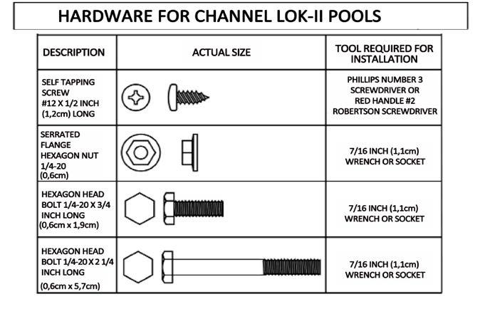
36 Parts List and Overview of Buttress Assembly KEY Part Name 1 Upright 2 Diagonal 4 Diagonal bracket 8 Strap 11 Hold down plate 13 Curved bottom rail 14 Base plate 18 Top plate 20 Rail Support 23 Base plate KEY Part Name - Hardware bag,1 per set of buttresses; includes; 10 1/4 "-20NC serrated flange hex bolt 12 No.12x1/2" self-tapping screw, pan head Phillips 21 1/4"-20NC x 3/4" hex bolt 26 1/4"-20NC x 2-1/4" hex head bolt
37 1-17
 from the outside edge of the patio stone. 30 c.")

38 7. Strap Preparation for the Buttresses a. Gently flatten any kinks or bends out of the straps (key 8). b. Lay the strap across the levelled area for the pool as shown in diagram 30. Centre the strap over the patio stone as shown in diagram 30. Space the end of the strap 2-1/4" (6 cm) from the outside edge of the patio stone. 30 c. Fasten one diagonal bracket (key 4) to the strap (key 8) using four 3/4" long bolts (key 21) and nuts (key 10). Make sure the angled part of the bracket is facing the correct direction as shown in diagram 32. The surface that the diagonal bracket is fastened to will be the top of the strap d. Repeat steps (a) to (c) for the other end of the strap e. Repeat steps (a) to (d) for the other straps. 1-18
, drag along the top edge of the strap to ensure the ground is exactly even and level with the strap (the area 24\" (61 cm) beyond each")

39 8. Installing the Upright a. Using a straight edge (you can use one of the hold down plates), drag along the top edge of the strap to ensure the ground is exactly even and level with the strap (the area 24" (61 cm) beyond each side of the strap must be level too). If it is not level, spread some crushed limestone (or equivalent) on the ground. Stand on the strap and tamp it down hard with a tamping tool. Verify the ground is level to the strap by running the straight edge along the top edge of the strap. Repeat this step until the ground is level. 33 b. Gently lift the strap and insert four 3/4" long bolts (key 21) into the holes closest to the centre of the pool. Ensure the bolt heads are facing the ground. Lay the strap back down on the ground and place the hold down plate and base plate (as shown in diagram 36) over the bolts protruding from the strap and fasten the nuts to the bolts and tighten
 to the base plate using three 3/4\" long bolts (key 21) and nuts (key 10). Make sure the bottom end of the upright is fastened to the base plate.")

40 Caution: Failure to properly install and tighten all of the bolts and nuts may void the warranty on your pool. c. Fasten one upright (key 1) to the base plate using three 3/4" long bolts (key 21) and nuts (key 10). Make sure the bottom end of the upright is fastened to the base plate. The bottom end of the upright has three large holes which are used to fasten to the base plate d. When you come to section 2, you will install the bottom rails, linking them to the buttresses. Make sure now that there is approximately a 1/16" (2 mm) gap under the tab at the bottom of each upright so the bottom rails slide on easily. e. Repeat steps (a) to (d) for the other side of the pool. 9. Install the Diagonals 38 1 a. Hold one diagonal brace 2 (key 2) approximately horizontal, insert the four 39 tabs at the end of the diagonal into the slots in the upright (key 1) (see diagram 39). Important: Ensure all four tabs at the end of the diagonal are inserted into the slots in the upright. b. Pull upward on the inserted end of the diagonal to make the tabs slide up and lock into position in the slots. At the same time, swing the other end of the diagonal down onto the diagonal bracket (key 4) on the base channel (see diagrams 40 and 41)
 with two 2-1/4\" (57 mm) bolts (key 26) and nuts (key 10). Do not overtighten the bolts.")
 and (E) and between (F) and (G). These will be used as a reference to make sure the buttresses are exactly lined up with each other.")
41 Very important: as you swing the diagonal down, make sure you apply constant upward pressure on the end of the diagonal brace with the tabs to ensure they stay fully locked in position in the slots. c. Fasten the bottom end of the diagonal brace to the diagonal bracket (key 4) with two 2-1/4" (57 mm) bolts (key 26) and nuts (key 10). Do not overtighten the bolts. They only need to be snug enough to ensure a secure fit (see diagram 42). d. Repeat steps (a) to (c) for the other side of the pool. e. Repeat steps (7) to (9) for the rest of the buttresses. 10. Buttress Location Verification a. Tie strings between stakes (D) and (E) and between (F) and (G). These will be used as a reference to make sure the buttresses are exactly lined up with each other. Stand at each corner of the pool and check the alignment of the buttresses with the strings. b. Jump to Section 2 and complete steps 1(a) and (b). This will allow you to install the bottom buttress rails, ensuring the correct distance between the buttresses. Important: complete only steps 1(a) to (c) for now, and then continue with step 11 below; you will complete the rest of Section 2 later. 11. Fill in the Hold Down Plates a. Standing on the hold down plate, insert material into all open voids on the 43 outside edges of the hold down plates until they are full. These voids are the open areas between the ground and the top edges of the hold down plate. Important: After the ends of the This will prevent any low spots from hold down plate has forming around the hold down plates been filled with material, place a sheet of when the pool is filled with water. plastic (approximately 15" x 15" (38cm x 38cm)) at each end of the hold down plate. This will prevent any additional material from flowing into the ends of the hold down plate that may cause low spots to form around the plates
 for the other hold down 45 plates. 12. Remove the strings and stakes a.")
42 Important: Make sure each hold down plate lies completely flat. The hold down plate must lie flat or it may lift and damage the pool liner after the pool is filled with water. b. Repeat step (a) for the other hold down 45 plates. 12. Remove the strings and stakes a. Make sure all of the strings and stakes (except stakes (A) and (B)) are removed from the entire pool area and fill in any holes with crushed limestone (or equivalent). Leave stakes (A) and (B) in place for now; they will be used later to centre the pool wall. b. Measure the two intersecting axes to ensure that the two straight sections are parallel
43 ATLANTIC 7050 Saint-Patrick Street La Salle (QC), H8N 1V2, Canada Notes: 1. Perimeter of the wall is 595" 2. Length of the wall is 596" 3. All dimensions are in inches unless otherwise specified. 4. All dimensions are referenced from the wall location. 5. Manufacturers tolerances and field condition may result in dimensional variations. DO NOT measure rail like this 12 x 18 Footprint measure rail like this Gap in the end side between Bottom Rails in the Base Plate is 0.599" END SIDE - Bottom Rail 44-3/4" X 6'R X 8 Places - Upper Rail 45 1/2" X 5'6"R X 8 Places G:\RnD\01-Projets\NLR-Atlantic\ATLANTIC Juan \GIBRALTAR 1218 A.3dm STRAIGHT SIDE - Upper Rail 8" X 9'R X 2 Places NLR NLR NLR NLR '-8" 12'-0" R6'-5" 12'-10" 12'-3" Strap3'-11"(2 Places) NLR '-7" NLR NLR '-0" NLR TRANSITION A - Bottom Rail 55-7/8" X 9'R X 4 Places - Upper Rail 56 3/4" X 9'R X 4 Places Gap in the straight side between Bottom Rails in the Vertical Clips is 4" 4'-9" 17'-5" 1-23
44 ATLANTIC 7050 Saint-Patrick Street La Salle (QC), H8N 1V2, Canada Notes: 1. Perimeter of the wall is 739" 2. Length of the wall is 740" 3. All dimensions are in inches unless otherwise specified. 4. All dimensions are referenced from the wall location. 5. Manufacturers tolerances and field condition may result in dimensional variations. STRAIGHT SIDE - Upper Rail 8" X 9'R X 2 Places STRAIGHT SIDE - Bottom Rail 44 5/8" X 12'R X 4 Places - Upper Rail 42 1/8" X 12'R X 4 Places NLR NLR NLR NLR NLR NLR NLR NLR NLR DO NOT measure rail like this 12 x 24 Footprint NLR NLR NLR '-3 3/4" 12'-5" 14'-5".. 14'-5" measure rail like this 12'-0" R6'-2" 11'-8" Strap3'-11"(2 Places) NLR NLR NLR '-10" NLR NLR Gap in the end side between Bottom Rails in the Base Plate is 0.329" NLR NLR NLR '-2" NLR NLR NLR TRANSITION A - Bottom Rail 44 5/8" X 9'R X 4 Places - Upper Rail 45 5/8" X 9'R X 4 Places 3'-10" END SIDE - Bottom Rail 44 5/8" X 6'R X 8 Places - Upper Rail 45 1/2" X 5'6"R X 8 Places 4'-0" Gap in the straight side between Bottom Rails in the Vertical Clips is 4" 23'-8" G:\RnD\01-Projets\NLR-Atlantic\ATLANTIC Juan \GIBRALTAR 1224 A.3dm 1-24
45 ATLANTIC 7050 Saint-Patrick Street La Salle (QC), H8N 1V2, Canada Notes: 1. Perimeter of the wall is 781" 2. Length of the wall is 782" 3. All dimensions are in inches unless otherwise specified. 4. All dimensions are referenced from the wall location. 5. Manufacturers tolerances and field condition may result in dimensional variations. STRAIGHT SIDE - Upper Rail 8" X 9'R X 4 Places STRAIGHT SIDE - Bottom Rail 44 5/8" X 12'R X 2 Places - Upper Rail 44 1/8" X 12'R X 2 Places NLR NLR NLR NLR NLR NLR NLR NLR '-0". 8'-2" 15'-6 1/4".. 15'-6 1/4" 15 x 24 Footprint DO NOT measure rail like this R7'-9" NLR NLR '-6" measure rail like this 14'-7 1/4" StrapP3'-8 1/2"P(6 Places) NLR NLR '-4 1/4" Gap in the end side between Bottom Rails in the Base Plate is 0.563" NLR NLR '-11 3/4" NLR NLR NLR NLR '-9 1/4" END SIDE - Bottom Rail 55 7/8" X 7'6"R X 8 Places - Upper Rail 57 5/8" X 7'6"R X 8 Places TRANSITION A - Bottom Rail 56-1/8" X 12'R X 4 Places - Upper Rail 56 3/4" X 12'R X 4 Places 4'-0" Gap in the straight side between Bottom Rails in the Vertical Clips is 4" 23'-7 3/4" G:\RnD\01-Projets\NLR-Atlantic\ATLANTIC Juan \GIBRALTAR 1524 A.3dm 1-25
46 ATLANTIC 7050 Saint-Patrick Street La Salle (QC), H8N 1V2, Canada Notes: 1. Perimeter of the wall is 925" 2. Length of the wall is 926" 3. All dimensions are in inches unless otherwise specified. 4. All dimensions are referenced from the wall location. 5. Manufacturers tolerances and field condition may result in dimensional variations. STRAIGHT SIDE - Upper Rail 8" X 9'R X 6 Places STRAIGHT SIDE - Bottom Rail 56-1/8" X 12'R X 4 Places - Upper Rails 51" X 12'R X 4 Places NLR NLR NLR NLR NLR NLR NLR NLR NLR DO NOT measure rail like this NLR NLR NLR x 30 Footprint. 17'-11 3/4" measure rail like this 15'-6 1/4" 15'-0" R7'-9". 14'-1 1/4" 17'-11 3/4". 14'-7 1/2" 12'-4 1/2" Gap in the end side between Bottom Rails in the Base Plate is 0.659" NLR NLR NLR NLR NLR StrapP3'-8 1/2"P(9 Places) NLR NLR NLR NLR NLR NLR NLR '-0" END SIDE - Bottom Rail 55 7/8" X 7'6"R X 8 Places - Upper Rail 57 5/8" X 7'6"R X 8 Places NLR NLR NLR TRANSITION A - Bottom Rail 56-1/8" X 12'R X 4 Places - Upper Rail 56 3/4" X 12'R X 4 Places 4'-9 1/2" 4'-11 1/2" Gap in the straight side between Bottom Rails in the Vertical Clips is 4" 29'-7 1/4" G:\RnD\01-Projets\NLR-Atlantic\ATLANTIC Juan \GIBRALTAR 1530 A.3dm 1-26
47 NLR NLR NLR NLR NLR NLR NLR NLR NLR NLR NLR NLR NLR NLR NLR ATLANTIC 7050 Saint-Patrick Street La Salle (QC), H8N 1V2, Canada Notes: 1. Perimeter of the wall is 1036" 2. Length of the wall is 1037" 3. All dimensions are in inches unless otherwise specified. 4. All dimensions are referenced from the wall location. 5. Manufacturers tolerances and field condition may result in dimensional variations. STRAIGHT SIDE - Upper Rail 8" X 9'R X 6 Places STRAIGHT SIDE - Bottom Rail 56-1/8" X 12'R X 4 Places - Upper Rails 51" X 12'R X 4 Places NLR NLR NLR DO NOT measure rail like this NLR measure rail like this 18 x 33 Footprint. 20'-6 1/2" Gap in the end side between Bottom Rails in the Base Plate is 0.403" 18'-5 1/4" 18'-0" R9'-2 1/2". 14'-1 3/4" 20'-6 1/2". 17'-8 1/4" 15'-9 3/4" END SIDE - Bottom Rail 55-7/8" X 9"R X 6 Places - Upper Rail 56-3/4" X 9"R X 6 Places StrapP4'-8 1/2"P(9 Places) 12'-10 3/4" NLR '-1 3/4" TRANSITION B - Bottom Rail 56-1/8" X 12'R X 4 Places - Upper Rail 56-3/4" X 12'R X 4 Places NLR NLR NLR TRANSITION A - Bottom Rail 56-1/8" X 12'R X 4 Places - Upper Rail 56-3/4" X 12'R X 4 Places 4'-9 1/2" 4'-11 1/2" Gap in the straight side between Bottom Rails in the Vertical Clips is 4" 32'-6 3/4" G:\RnD\01-Projets\NLR-Atlantic\ATLANTIC Juan \GIBRALTAR 1833 A.3dm 1-27
. The rails are colour coded or stamped with a part number.")
48 Section 2 Pool Component Installation Manual Assembling the Pool Base & Side Buttresses 1. Install the Curved Bottom Rails a. Each pool uses two, three or four different types of curved bottom rails (key 13). The rails are colour coded or stamped with a part number. Use the chart below to choose the types and quantities of bottom rails for your pool (part numbers are shown in brackets under each colour). Quantity and Colour Code (with part numbers) Pool Size Buttress Rail Transition Rail A Transition Rail B End Rail 12' x 18' (3,66m x 5,49m) n/a 4 yellow n/a 8 plain (no ) (no ) 12' x 24' (3,66m x 7,32m) 4 white 4 blue n/a 8 plain (no ) (no ) (no ) 15' x 24' (4,57m x 7,32m) 2 white 4 orange n/a 8 plain (no ) (no ) (no ) 15' x 30' (4,57m x 9,14m) 4 green 4 orange n/a 8 plain (no ) (no ) (no ) 18' x 33' (5,49m x 10,05m) 4 green 4 orange 4 orange 6 plain (no ) (no ) (no ) (no ) (n/a=not applicable; plain=no colour code) The 18 x 33 (5,49m x 10,05m) pool is the only size that uses all four types of rails. Diagram 1 shows the locations for each type

. 1. Set the Pool Wall in place a.")
49 Section 3 Hint: Bring the following items onto the pool foundation before you start uncoiling the pool wall: the pool liner, some extra brick sand to make the cove in Step 5, and a ladder to climb out after the wall is assembled. Caution: Do not attempt to install the pool wall in the wind. Wait for a calm day. Hint: Secure the omega stabilizer to the wall with a piece of duct tape after installation to prevent it from lifting off the wall. Pool Component Installation Manual Assembling the Pool Wall & Liner A. Assemble your Pool Wall This section is for Round and Oval pools (ROUND POOLS ARE SHOWN). 1. Set the Pool Wall in place a. Wait for a calm day. Do not attempt to install the pool wall in the wind. b. Unpackage the coiled pool wall and stand it on a piece of cardboard or plywood at the centre of the pool. The cut-outs for the through-the-wall skimmer should be towards the top of the wall. Look for a this way up label and arrow. Make sure the skimmer and water return holes are where you need them to be. The skimmer and water return holes are positioned towards the end of the pool wall. (The section before the wall started). c. Start uncoiling the wall, guiding the bottom edge into the curved bottom rail. The starting end of the wall must be positioned over a bottomplate, and the skimmer and return holes should be positioned where the pump and filter will be. Set lengths of Omega Stabilizer onto the top edge of the wall as you uncoil it
 are colour coded or stamped with a part number.")
50 Hint: Using a 2" (5 cm) piece of duct tape, tape the ends of the 6" (15 cm) metal slotted tube connector over the slotted tubes and onto the pool wall. This will prevent the slotted tubes from moving during liner installation. d. The slotted tubes (Omega Stabilizer) are colour coded or stamped with a part number. Use the chart below to choose the types and quantities of slotted tubes for your pool (part nos. are shown in brackets under each colour). Set lengths of slotted tube onto the top edge of the wall as you uncoil it and join the slotted tubes with connectors as you go, leaving a 1/2" (13 mm) gap between each. (If you have a beaded pool liner, set lengths of liner retainer on the top edge of the wall first, then the slotted tubes and connectors.) Quantity and Colour Code (with part numbers) Pool Size Buttress Tube Transition Tube A Transition Tube B End Tube 12' x 18' (3,66m x 5,49m) n/a 4 yellow n/a 8 plain (no ) (no ) (no ) (no ) 12' x 24' (3,66m x 7,32m) 4 white 4 blue n/a 8 plain (no ) (no ) (no ) (no ) (no ) (no ) 15' x 24' (4,57m x 7,32m) 2 white 4 green n/a 8 plain (no ) (no ) (no ) (no ) (no ) (no ) 15' x 30' (4,57m x 9,14m) 4 green 4 green n/a 8 plain (no ) (no ) (no ) (no ) (no ) (no ) 18' x 33' (5,49m x 10,05m) 4 green 4 green 4 green 6 plain (no ) (no ) (no ) (no ) (no ) (no ) (no ) (no ) (n/a=not applicable; plain=no colour code) Hint: Secure the omega stabilizer connector to the wall with a piece of duct tape after installation to prevent it from lifting off the wall. The 18 x 33 pool is the only size that uses all four types of slotted tubes. Diagram 5 shows the locations for each type Hint: Stick a screwdriver through two of the holes to help line up the ends of the wall

51 NOTE: We also suggest installing vinyl-covered hooks and rope to hold the wall steady. e. Work around the foundation until the entire pool wall is uncoiled into the bottom rails and the top edge is covered with the omega stabilizer and connectors (and beaded liner retainers if you have a beaded pool liner) 4a Hint: Secure the omega stabilizer connector to the wall with a piece of duct tape after installation to prevent it from lifting off the wall. Hint: Stick a screwdriver through two of the holes to help line up the ends of the wall. 2. Join the Ends of the Pool Wall a. Line up the holes in the two ends of the pool wall. b. To line up the holes, make the circle bigger or smaller by nudging the base plates in or out with your foot. c. To fasten the wall joint, overlap the two steel bars, one on the inside and the other on the outside. Tighten the mechanical screws on the inside and the nuts on the outside. Make sure there is a bolt in each hole. NOTE: When tightening the screws start from either the top and go down or vice versa. do not start a few screws from top and a few from the bottom to meet in the middle, this can cause problems later on d. Ensure that all bolts and all the holes are used. e. Cover the seam and bolt heads on the inside of the pool wall completely with 2 layers of 2" (50 mm) duct tape
 high and 8 to 12 (20cm to 30cm) wide at ground level.")


52 Remember: The cove is an important part of the pool structure. Take your time to make a complete, full-size cove. 4. Make a Cove a. If you are using sand, bank the sand against the wall to form a cove of 3 to 6 (7.5cm to 15cm) high and 8 to 12 (20cm to 30cm) wide at ground level. This will prevent the liner from creeping under the wall, and it will also protect the liner from any metal edges of the pool framework. THIS STEP IS NOT OPTIONAL, IT MUST BE DONE.. 11 b. Water the sand to compact it and use a trowel to spread it evenly. Remember: The bolt heads must be toward the inside of the pool. Cover the bolt heads with duct tape. c. Since earth containing chemicals can cause discoloration or corrosion, it is suggested that you place polyethylene plastic sheeting under the cove around the perimeter of the wall, so no earth comes in contact with the metal. Since the presence of such chemicals is beyond the control of the manufacturer, such damage is not covered under warranty. d. If you are using styrofoam cove pieces instead of sand, insert them in the bottom rail and refer to the installation instructions that are provided with them

 above the cove (insert through the water return outlet or the skimmer depending on the diameter of your hose).")
53 e. A vacuum cleaner can later be used to remove the air from between the liner and the wall. This technique enables you to remove folds in the liner. However the following precautions should be taken: Do not use an industrial vacuum cleaner which could be too powerful. 14 Tape the end of the vacuum hose before inserting it into the wall so as not to damage the liner. Insert the nozzle until it is about 4 (10cm) above the cove (insert through the water return outlet or the skimmer depending on the diameter of your hose). Make sure you will be able to remove the hose later on. Tape the hose to the wall. 15 f. Close the skimmer opening with cardboard and adhesive tape so that the suction of air works better.. 3-5


54 B. Install your Pool Liner 1. Set the liner in place a. Open the carton. Do not use anything sharp to open the carton. b. Unpack and unfold the liner and spread it out in the sun to warm it up. Inspect all the seams and surfaces for holes. Hint: If possible, unfold the liner on the grass one to two hours before installation. Be careful not to leave the liner too long or you may damage the grass. c. Remove your shoes to avoid damaging the base or tearing the liner. d. Spread out the liner, smooth side down. Unfold the liner from the centre of the pool toward the sides. 16 Hint: The liner is generally smaller than the support structure of the pool. It will stretch more easily when warm. It is important that the liner is installed on a warm sunny day. e. Use the liner's bottom seam(s) as a guide and make sure the seam(s) are parallet to the straight sections and to the imaginary line which links points A and B in the illustration 16a. It is recommended that you begin installing the liner in a round 16a section. f. Use the liner's vertical seam as a gide and make sure the sea is vertical and perpendicular to the wall and bottom. g. Make sure the seam between the wall and bottom is centred on the cove. g. Smooth out all the wrinkles in the bottom. Do not leave any space between the liner and cove
 Instead, roll up any excess liner and tape it in place near the top of the pool wall. 2.")
This will assure you that the liner be")
55 Important: This step applies only if you have an Overlap Liner. See next page for Beaded Liner or V-Bead Liner. Important: Do not trim off the excess liner. (If the liner ever needs to be removed, trimming the liner will make re-installation very difficult.) Instead, roll up any excess liner and tape it in place near the top of the pool wall. 2. Fasten the Liner in place (Overlap Liner only) a. Starting at the liner wall seam, hang the liner over the wall making sure that the seam is straight up and down, perpendicular to the floor. (Remove stabilizers gradually as you fold the liner over the top of the wall. )This will assure you that the liner begins going over the wall straight. b. As you put the liner over the wall you can secure it by using the plastic coping strips to keep it in place. If you end up with excess material, continue around the pool, pulling excess liner evenly, and distribute over the wall until the excess is gone. 18 c. Fasten the liner to the top of the wall with plastic coping. Let the liner hang slack for now. Do not pull the Plastic Coping liner tight. NOTE: Some liners may fit very tightly, it is better to install uprights, top plate and top ledge before going onto next step. See Section 4. d. Turn the vacuum cleaner on and Liner Overlap push the liner outward with your Outside Pool Wall feet to iron out any wrinkles. Once 19 finished, turn off vacuum cleaner. e. Start filling the pool with water. As the pool fills, work out all the wrinkles and smooth the liner to the wall. Remove the plastic coping around the top edge of the wall one piece at a time and adjust the liner. Keep 20 smoothing out the wrinkles. f. After all the wrinkles in the liner are removed, trim any extra length of plastic coping so there is no overlap. g. Roll up any excess liner hanging below the plastic coping and tape it in place near the top of the pool wall. Important: Do not trim off the excess liner
56 3. Fasten the Liner in place (HUNG/J or V-BEAD LINER ONLY) a. With a V-Bead liner you will not use the plastic coping strips that are packed in the parts carton of your pool. You can discard those pieces, if they are included, as they only apply to pools with overlap liners. Remember: Do not trim off the excess liner. (If the liner ever needs to be removed, trimming the liner will make re-installation very difficult.) Instead, roll up any excess liner and tape it in place near the top of the pool wall. b. The top of the wall of the liner has what is called a V-Bead welded onto it. Simply open up the bead with your fingers and hang it directly on top of the pool wall. When this is done properly, the only portion on the outside of the pool wall is approximately 1 of the V-Bead. No printed liner material is actually going over the top of the wall to the outside of the wall c. Make sure the bead is on evenly around the entire pool, and that the liner is hanging straight down from the top of the wall. The liner should not have creases in it because it is twisting around the pool. If the liner is twisting, it is because it is not sitting properly in the pool. Make necessary adjustments before proceeding. NOTE: Some liners may fit very tightly, it is better to install uprights, top plate and top ledge before going onto next step. See Section
57 4. Fasten the liner place (BEADLOCK/SNAPBEAD LINER ONLY) a. With a snap bead liner you will not use the plastic coping strips that are packed in the parts carton of many pools. You can discard those pieces (if they are included). Instead, you should have received a beaded liner track (referred to as a coping bead receiver in this image). b. The beaded liner track should be installed onto the pool wall all of the way around the pool. These pieces should be as close together as possible. Leaving spaces between bead tracks can cause liner problems later on. c. Once all of the beaded liner track is on the wall, you can snap the liner bead into the beaded liner track at four random points around the pool. After that is done, and you are satisfied with how the liner is situated within the pool, you can continue snapping the remainder of the liner into place around the pool. d. Go around the entire pool again making certain that the liner is securely snapped into the track. This is important to confirm so that the liner does not pull out while under the pressure of being filled with water. 23 NOTE: Some liners may fit very tightly, it is better to install uprights, top plate and ledge before going onto next step. See Section Proceed to Section 4 - Assembling the Pool Frame 3-9
58
 of water until the top ledges and vertical uprights are all attached. b. Keep working on the top ledges and uprights while the pool fills.")
 with the two small tabs on one base plate (key 2). The tabs must be on the inside of the upright. b. Line up the screw holes and fasten with one self-tapping screw on each side (key 3).")
59 Section 4 Pool Component Installation Manual Installing the Top Ledges & Uprights A. Attach your Uprights and Top Ledges 1. Continue filling your Pool a. Continue filling your pool with water. Do not put in more than 12" (30 cm) of water until the top ledges and vertical uprights are all attached. b. Keep working on the top ledges and uprights while the pool fills. See the drawing on the next page for an overview of all the parts used to install the uprights, top ledges and ledge covers. 2. Install the Uprights a. Line up the bottom of one upright (key 1) with the two small tabs on one base plate (key 2). The tabs must be on the inside of the upright. b. Line up the screw holes and fasten with one self-tapping screw on each side (key 3) Hint: Use the ridges in the pool wall to make sure the upright is straight up and down. c. Hook a top plate (key 4) over the top edge of the pool wall (key 5). Place the top plate down over the top of the upright with the tabs on the inside of the upright. Make sure the upright is straight up and down. d. Line up the screw holes and fasten with one self-tapping screw on each side and one on the front (key 6). e. Repeat the last four steps for each of the uprights around the pool wall I f. Adjust all the top ledges to line up ev. 4-1

60 Overview of Upright, Top Ledge and Ledge Cover Assembly
. Do not tighten any of the screws yet.")
 a. Important: the four transition A top ledges are mitred at the ends.")
61 3. Install the Top Ledges (Straight Section) a. Install the side ledges between the buttress. Use hole 'A' and line up all of the holes as shown in diagram 5. Fasten throught the two oval holes to the top plate below with two self-tapping screws (key 9). Do not tighten any of the screws yet. Leave the screws slightly loose until all the top ledges are in place. Make sure the uprights are aligned straight up and down (Note: the 12' x 18' pool does not have side ledges). b. Verify the remaining vertical as shown in this Section Install the Top Ledges (Transition Section) a. Important: the four transition A top ledges are mitred at the ends. Only the end of the transition A top ledge that is over a buttress will fasten into the hole marked 'B' in the top plate, 4 as shown in diagram 4. For the rest of the end ledges, use hole 'A' and line up all of the holes as shown in diagram 5. Fasten through the tow oval holes to the top plate below with two self-tapping screws (key 9). 3 Do not tighten any of the screws yet. Leave the screws slightly loose until all the top ledges are in place

62 b. IMPORTANT: if any of the verticals are not straight up and down, adjust the base plate and bottom end of the vertical side to side as required by gently tapping on the base plate with a hammer and a block of wood. If you need to adjust the top of the vertical, you may need to remove the top plate first or else the wall and the liner could be dammaged. c. Check the length of the second transition A top rail before you fasten it. If the end of the transition rail overlaps the side rail, it needs to be cut; if the oval holes of the transition rail overlaps the side rail, it needs to be cut; if the oval holes of the transition rail do not match the holes in the top plate, you must drill new holes. (Note: the 12' x 18' pool does not have side rails, any overlap will be over the adjacent transition rail). In the case that the transition rail seems to be too short, you must pull the rails you just installed so the end of the transition rail can be attached to the top plate. The oval holes provide approximately 2" (51 mm) adjustment at each end of the pool. c. Repeat steps (b) and (c) for the other side of the pool. 5. If the transition rail needs to be drilled and/or cut follow these steps: a. Temporarily unscrew the end of the side rail that is next to the transition rail. (Note: the 12' x 18' pool does not have side rails) b. Place one end of the transition rail (key 8) underneatht the side rail. (Note: for the 12' x 18' pool place one end above the other transition rail). Place the other end ovver the first vertical on the round end of the pool and temporarily fasten this end midway of the adjustment provided by the oval holes. If you have a 12' x 18' pool, jump to step (k) now
63 c. With the end of the side rail on top of the transition rail, mark two dimension 1/2" (13mm) and 1-1/8" (29mm) away from the end of the side rail. Then temporarily unscrew the other end of the side rail and move it to draw the lines X and Y. The first line X is parallel to the end of the side rail, 1/2" (13mm) away. 9 This will be the line you will cut along to shorten the transition rail. The seconde line Y is also parallel to the end of the side rail, 1-1/8" (29mm) away. this will be the line that the new 1/4" (6mm) screw holes lie on. d. To mark the locations of the 1/4" (6mm) screw holes, draw two lines through the centres of each of the two oval holes, parallel to the length of the rail, to intersect the line Y. The intersection of these lines will determine the locations of the new 1/4" (6mm) screw holes that need to be drilled. e. If you pool calls for a support plate, drill another 1/4" (6mm) hole 1-1/2" (38mm) or 2-1/8" (54mm) toward the inside of the pool along the line Y. Measure the distance on your pool. f. Remove the transition rail and drill the 1/4" (6mm) holes using the marks that lie on the line Y. g. Cut the transition rail along the 1/2" (13mm) line X using a hacksaw (use a blade with at least 32 teeth per inch). h. Fasten the side rail and the tranistion rail in place. i. Repeat steps (a) to (h) to install the top rails at the other end of the pool. j. Continue with with Step 4 in this Section
64 6. Install the Ledge Covers a. Loosen the front screw used to secure the top plate to the upright. b. Place a bottom ledge cover against an upright as shown in diagram 1. c. Slide the bottom ledge cover upwards until the slot on the ledge cover rests under the screw. d. Tighten the screw and repeat for the other uprights. e. Coat all showing screw heads with clear outdoor varnish. IMPORTANT: When installing the top ledge cover, ensure the front lip of the ledge cover is over the top lif of the bottom ledge cover

65 B. Fill your Pool with Water 1. Finish filling the pool a. Turn off the vacuum and carefully remove it from the pool. b. Fill the pool with water to 2 (5cm) below the lowest opening. Make sure you remove any creases from the liner in the bottom of the pool before the water level gets too high. Caution: Before making any openings in the liner, fill the pool with 60cm (24 ) of water to stretch the liner fully. When filling your pool, begin with a garden hose until there is about 30cm (12 ) of water in the pool. This will allow the liner to stretch gradually. You can then use a heavier flow to finish filling it up. c. While the pool is filling, remove the nails that were holding the bottom rails in place. d. Your pool is now installed. You must now install the filter and pump, the skimmer and water return inlet.please follow the installation instructions that come with these products. Important: Make sure that your pool is round, do not assume that by filling up the pool that this will help the pool to place itself into a perfect round circle. Ensure that it is round before filling up the pool with water. IMPORTANT SAFETY INFORMATION: Please refer to the safety page at the beginning of this instruction manual. You must follow the rules and information regarding placement of safety stickers on your pool. 4-7
Pool Component Installation Manual. A. Introduction to Installing your Pool
 SECTION 1 Pool Component Installation Manual General Instructions A All Round Pools Part No. 1920283 rev. 4 A. Introduction to Installing your Pool Read all instructions completely before you begin. These
Aboveground Pool Installation Manual
 97-0753 Aboveground Pool Installation Manual Thismanual must be left with the pool owner www.wilbargroup.com Section 1 GENERAL INSTRUCTIONS ROUND POOL GROUND PREPARATION Safety Rules for Pool Owners Your
This manual must be left with the pool owner. Pool Component Installation. Safety Rules For Pool Owners
 This manual must be left with the pool owner Pool Component Installation SECTION 1 Manual General Instructions A All Round Pools Part No. 1920283 rev. 4 Safety Rules For Pool Owners Your pool contains
V35046 INSTALLATION MANUAL - ROUND POOLS POOL MODEL - Caribbean 11.13
 V35046 INSTALLATION MANUAL - ROUND POOLS POOL MODEL - Caribbean 11.13 Above Ground Pool Safety Please read before installation warning Failure to heed these warnings can result in permanent injury, paralysis
Pool Component Installation Manual. A. Introduction to Installing your Pool
 SECTION 1 Pool Component Installation Manual General Instructions A All Round Pools Part No. 1920283 rev. 4 A. Introduction to Installing your Pool Read all instructions completely before you begin. These
Saltwater Series SALTWATER 8000 INSTALLATION MANUAL ROUND POOL 01.16
 Saltwater Series SALTWATER 8000 INSTALLATION MANUAL ROUND POOL 0.6 Above Ground Pool SAfety PleASe read before installation warning Failure to heed these warnings can result in permanent injury, paralysis
V35047 INSTALLATION MANUAL - CHANNEL LOK II OVAL POOLS POOL MODEL - Caribbean 11.13
 V35047 INSTALLATION MANUAL - CHANNEL LOK II OVAL POOLS POOL MODEL - Caribbean 11.13 Above Ground Pool Safety Please read before installation warning Failure to heed these warnings can result in permanent
V35041 MAGNUS RTR POOL MODEL INSTALLATION MANUAL - ROUND POOLS
 V35041 MAGNUS RTR POOL MODEL INSTALLATION MANUAL - ROUND POOLS 11.13 Above Ground Pool Safety Please read before installation warning Failure to heed these warnings can result in permanent injury, paralysis
General Instructions
 This manual must be left with the pool owner Pool Component Installation SECTION 1 Manual General Instructions Safety Rules For Pool Owners Gibraltar Oval Pools Part No. 1920585 rev. 0 Your pool contains
V Montego POOL MODEL INSTALLATION MANUAL - OVAL POOLS 11.13
 V35042 Montego POOL MODEL INSTALLATION MANUAL - OVAL POOLS.3 Above Ground Pool Safety Please read before installation warning Failure to heed these warnings can result in permanent injury, paralysis from
P/N S OVAL POOL INSTALLATION MANUAL
 P/N 39184 S OVAL POOL INSTALLATION MANUAL ABOVE GROUND POOL SAFETY PLEASE READ BEFORE INSTALLATION warning FAILURE TO HEED THESE WARNINGS CAN RESULT IN PERMANENT INJURY, PARALYSIS FROM A BROKEN NECK, ELECTROCUTION
V35034 INSTALLATION MANUAL
 V35034 INSTALLATION MANUAL BRACELESS OVAL POOLS INSPIRATION REGENCY (STR/RTR/LX) 0.7 ABOVE GROUND POOL SAFETY PLEASE READ BEFORE INSTALLATION warning FAILURE TO HEED THESE WARNINGS CAN RESULT IN PERMANENT
Installing the Top Rails & Verticals
 Additional Installation Information Important Read Me First For Esprit Round Pools SECTION 4 Esprit Round Pools Part No. 1920717 rev. 0 Installing the Top Rails & Verticals When you come to Section 4,
V35042 INSTALLATION MANUAL
 V35042 INSTALLATION MANUAL BRACELESS OVAL POOLS ZENITH CAMILIA ENIGMA SIMBIO VECTRA MAGNUS OHANA 0.7 ABOVE GROUND POOL SAFETY PLEASE READ BEFORE INSTALLATION warning FAILURE TO HEED THESE WARNINGS CAN
V35013 REFLEXION INSTALLATION MANUAL ROUND POOL
 V35013 REFLEXION INSTALLATION MANUAL ROUND POOL 10.14 Above Ground Pool Safety Please read before installation warning Failure to heed these warnings can result in permanent injury, paralysis from a broken
GENERAL INSTRUCTIONS Round Pool. for regular installation
 GENERAL INSTRUCTIONS Round Pool for regular installation ABOVE GROUND POOL SAFETY PLEASE READ BEFORE INSTALLATION FAILURE TO HEED THESE WARNINGS CAN RESULT IN PERMANENT INJURY, PARALYSIS FROM A BROKEN
V35032 IMPRESS POOL MODEL INSTALLATION MANUAL - OVAL POOLS
 V35032 IMPRESS POOL MODEL INSTALLATION MANUAL - OVAL POOLS 5.3 Above Ground Pool Safety Please read before installation warning Failure to heed these warnings can result in permanent injury, paralysis
V35009 INSTALLATION MANUAL - ROUND POOLS POOL MODEL - LIBERTY-ELIXIR-LEGEND
 V35009 INSTALLATION MANUAL - ROUND POOLS POOL MODEL - LIBERTY-ELIXIR-LEGEND 11.13 Above Ground Pool Safety Please read before installation warning Failure to heed these warnings can result in permanent
V35038 REVELATION-IMPULSE-PANACHE POOL MODEL INSTALLATION MANUAL - OVAL POOLS G:\RnD\01-Projets\Révélation\Revelation 15x22light 2D.
 G:\RnD\0-Projets\Révélation\Revelation 5x22light 2D.3dm V35038 REVELATION-IMPULSE-PANACHE POOL MODEL INSTALLATION MANUAL - OVAL POOLS.3 Above Ground Pool Safety Please read before installation warning
General Instructions
 This manual must be left with the pool owner Pool Component Installation SECTION 1 Manual General Instructions Safety Rules or Pool Owners Channel Lok-I Oval Pools Part No. 1920586 rev. 1 Your pool contains
GENERAL INSTRUCTIONS Oval Pool. for regular installation
 V Text / Full Color Version GENERAL INSTRUCTIONS Oval Pool for regular installation ABOVE POOL SAFETY PLEASE READ BEFORE INSTALLATION FAILURE TO HEED THESE WARNINGS CAN RESULT IN PERMANENT INJURY, PARALYSIS
Round pool 52 (1,32m)
") Round pool 52 (1,32m) www.aquabois.com above ground or semi-inground Instructions for the assembly and installation of a wood pool Dear client, Congratulations, you have purchased a pool of superior quality
Round pool 52 (1,32m) www.aquabois.com above ground or semi-inground Instructions for the assembly and installation of a wood pool Dear client, Congratulations, you have purchased a pool of superior quality
Evora ROUND ABOVE GROUND POOL INSTALLATION MANUAL V
 Evora ABOVE GROUND POOL ROUND INSTALLATION MANUAL V35076 03.17 ABOVE GROUND POOL SAFETY PLEASE READ BEFORE INSTALLATION warning FAILURE TO HEED THESE WARNINGS CAN RESULT IN PERMANENT INJURY, PARALYSIS
SALTWATER 8000 INSTALLATION MANUAL YARDMORE OVAL POOL
 Saltwater Series SALTWATER 8000 INSTALLATION MANUAL YARDMORE OVAL POOL 0.6 Above Ground Pool SAfety PleASe read before installation warning Failure to heed these warnings can result in permanent injury,
Relaxing Meadow ABOVE GROUND POOL OVAL INSTALLATION MANUAL
 Relaxing Meadow ABOVE GROUND POOL OVAL INSTALLATION MANUAL 95-0444 02.16 ABOVE GROUND POOL SAFETY PLEASE READ BEFORE INSTALLATION warning FAILURE TO HEED THESE WARNINGS CAN RESULT IN PERMANENT INJURY,
P/N S ROUND POOL INSTALLATION MANUAL
 P/N 395 S ROUND POOL INSTALLATION MANUAL ABOVE GROUND POOL SAFETY PLEASE READ BEFORE INSTALLATION warning FAILURE TO HEED THESE WARNINGS CAN RESULT IN PERMANENT INJURY, PARALYSIS FROM A BROKEN NECK, ELECTROCUTION
Edge ROUND ABOVE GROUND POOL INSTALLATION MANUAL V
 Edge ABOVE GROUND POOL ROUND INSTALLATION MANUAL V35037 03.17 ABOVE GROUND POOL SAFETY PLEASE READ BEFORE INSTALLATION warning FAILURE TO HEED THESE WARNINGS CAN RESULT IN PERMANENT INJURY, PARALYSIS FROM
Saltwater Series SALTWATER LX INSTALLATION MANUAL ROUND POOL 01.16
 Saltwater Series SALTWATER LX INSTALLATION MANUAL ROUND POOL 01.16 ABOVE GROUND POOL SAFETY PLEASE READ BEFORE INSTALLATION warning FAILURE TO HEED THESE WARNINGS CAN RESULT IN PERMANENT INJURY, PARALYSIS
V35037 REVELATION-IMPULSE-PANACHE POOL MODEL INSTALLATION MANUAL - ROUND POOLS G:\RnD\01-Projets\Révélation\Revelation 24' iso 2D.
 G:\RnD\01-Projets\Révélation\Revelation 24' iso 2D.3dm V35037 REVELATION-IMPULSE-PANACHE POOL MODEL INSTALLATION MANUAL - ROUND POOLS 11.13 Above Ground Pool Safety Please read before installation warning
SOLISTA PREMIUM METAL WALL POOL - BU1002 I/N ENDEAVOUR PREMIUM METAL WALL POOL - BU1003 I/N
 TM SOLISTA PREMIUM METAL WALL POOL - BU002 I/N 309024 ENDEAVOUR PREMIUM METAL WALL POOL - BU003 I/N 309025 OWNER'S MANUAL Congratulations on your new purchase! Your high performance Pool is designed to
St. Kitts 54" Round Pools
 St. Kitts 54" Round Pools Installation Instructions 573-3774/0317 Installation Instructions HOW TO USE THESE INSTRUCTIONS Be sure to read these instructions completely before beginning assembly or installation.
ABOVE GROUND POOL SAFETY
 P/N 95-0734 EXCURSION ABOVE GROUND ROUND SLAT INSTRUCTIONS ABOVE GROUND SAFETY WARNING FAILURE TO HEED THESE WARNINGS CAN RESULT IN PERMANENT INJURY, PARALYSIS FROM A BROKEN NECK, ELECTROCUTION OR DROWNING.
To purchase replacement parts and accessories, or to obtain technical assistance, visit:
 IMPORTANT Read this guide and follow all instructions carefully before assembling or using this product. To purchase replacement parts and accessories, or to obtain technical assistance, visit: www.splasharoundpools.com
REPRIEVE INSTALLATION MANUAL ROUND POOL 09.15
 95-0443 REPRIEVE INSTALLATION MANUAL ROUND POOL 09.15 48 PREP-48SSPSSN1 Product Description: Product Code: Reprieve Round PREP-48SSPSSN1 Quantity Required for Installation (by Pool Size) Index# Description
DANGER!! IMPORTANT NOTICE! READ BEFORE INSTALLATION
 Safety Information Your pool is designed for years of pleasurable, safe family fun. But when used incorrectly, a swimming pool can be dangerous. To insure your pool is used safely, you MUST observe the
INSTALLER: Once the installation of the pool is complete, it is important to give this document to the customer in person.
 A ECHO Dear Customer Congratulations! You have purchased a pool of superior quality and durability. To achieve the best possible results, follow the instructions carefully. Failure to follow the installation
7 & 9 Top Rail Pool Series 52 and 54 Oval Pools
 1989 560-1041 WARNING NO DIVING! Shallow water. You can be permanently injured. Copyright 7 & 9 Top Rail Pool Series 52 and 54 Oval Pools Installation Instructions 573-4036 Installation Instructions HOW
Excursion ABOVE GROUND POOL OVAL SLAT INSTALLATION MANUAL
 Excursion ABOVE GROUND POOL OVAL SLAT INSTALLATION MANUAL 95-0735 02.16 ABOVE GROUND POOL SAFETY PLEASE READ BEFORE INSTALLATION warning FAILURE TO HEED THESE WARNINGS CAN RESULT IN PERMANENT INJURY, PARALYSIS
LoneStar Fiberglass Pools. Do-It-Yourself. Installation Manual
 LoneStar Fiberglass Pools Do-It-Yourself Installation Manual Chris 1/3/2008 Do-It-Yourself The installation of a LoneStar Fiberglass pool is a much simpler task than most people think. What is important
ABOVE GROUND POOL SAFETY
 ABOVE GROUND ROUND POOL INSTRUCTIONS ABOVE GROUND POOL SAFETY WARNING FAILURE TO HEED THESE WARNINGS CAN RESULT IN PERMANENT INJURY, PARALYSIS FROM A BROKEN NECK, ELECTROCUTION OR DROWNING. THIS POOL IS
C Capri/Zephyr. INSTALLER: Once the installation of the pool is complete, it is important to give this document to the customer in person.
 C Capri/Zephyr Bora/Brisa Dear Customer Congratulations! You have purchased a pool of superior quality and durability. To achieve the best possible results, follow the instructions carefully. Failure to
Sharkline Deluxe ABOVE GROUND POOL ROUND INSTALLATION MANUAL
 Sharkline Deluxe ABOVE GROUND POOL ROUND INSTALLATION MANUAL 95-0443 02.16 ABOVE GROUND POOL SAFETY PLEASE READ BEFORE INSTALLATION warning FAILURE TO HEED THESE WARNINGS CAN RESULT IN PERMANENT INJURY,
MATRIX OVAL YARDMORE POOL INSTRUCTIONS
 V P/N 95-0432 03/08 MATRIX OVAL YARDMORE POOL INSTRUCTIONS Your pool is designed for years of pleasurable, safe, family fun. But, when used incorrectly, a swimming pool can be dangerous. To insure your
Relaxing Meadow ABOVE GROUND POOL ROUND INSTALLATION MANUAL
 Relaxing Meadow ABOVE GROUND POOL ROUND INSTALLATION MANUAL 95-0443 02.16 ABOVE GROUND POOL SAFETY PLEASE READ BEFORE INSTALLATION warning FAILURE TO HEED THESE WARNINGS CAN RESULT IN PERMANENT INJURY,
Cool Springs and Clarksville store call Cookeville store call Bowling Green store call
 Welcome to the Pool & Spa Depot family! The following guide is to help you understand what's involved in building your new above ground pool. Your above ground pool installation will require the following
STATIONARY TRUCK INTERNAL HALYARD V-CLEAT FLAGPOLES FOR QUICK AND PROFESSIONAL INSTALLATION READ ALL INSTRUCTIONS BEFORE PROCEEDING
 9390 South 300 West, Sandy, Utah 84070 801-562-0123 800-782-0500 ColonialFlag.com STATIONARY TRUCK INTERNAL HALYARD V-CLEAT FLAGPOLES FOR QUICK AND PROFESSIONAL INSTALLATION READ ALL INSTRUCTIONS BEFORE
Above Ground Pool Assembly & Installation
 P/N 95-0734 Above Ground Pool Assembly & Installation ROUND SLAT WALL WA R N I N G : THIS IS NOT DESIGNED FOR DIVING OR JUMPING. DANGEROUS INJURY CAN RESULT - SHALLOW WATER!!! Your pool is designed for
T A POOL ASSEMBLY AND INSTALLATION MANUAL. Above Ground Aluminum Delta Sheetwall Oval Pools
 T3667-60A POOL ASSEMBLY AND INSTALLATION MANUAL Above Ground Aluminum Delta Sheetwall Oval Pools Note: Deck and fence accessories shown are optional. THIS MANUAL EXPLAINS THE CORRECT METHOD TO ASSEMBLE
UNIVERSAL INSTRUCTIONS BRACED OVAL POOLS
 UNIVERSAL INSTRUCTIONS BRACED OVAL POOLS PLEASE READ THESE INSTRUCTIONS CAREFULLY AND THOROUGHLY BEFORE STARTING GROUND PREPARATION AND POOL ASSEMBLY. DOING SO WILL PREVENT PROBLEMS. Oval Pool: General
ROUND ASSEMBLY. Positioning
 ROUND ASSEMBLY Positioning To ensure maximum enjoyment and efficiency, consider the following steps when selecting the desired location of you pool. Select a location that receives maximum sunlight for
L.Ph. Bolander & Sons 1355 Evans Ave. 800/
 L.Ph. Bolander & Sons 1355 Evans Ave. 800/434-5611 San Francisco, Ca. 94124 Fax 415/648-0402 GOUNDSET ALUMINUM FLAGPOLE INSTALLATION INSTRUCTIONS STEP 1: DIG THE HOLE TO THE DIMENSIONS LISTED BELOW STEP
Safe Installation Procedures and Care Manual Meyco Safety Pool Covers
 Safe Installation Procedures and Care Manual Meyco Safety Pool Covers Meyco Products relies on the experience and knowledge of pool professionals to properly install our products. Damage that occurs to
Step 1. PLANNING FOR THE INSTALLATION TOOLS REQUIRED
 Installation Guide Fiji Step 1. PLANNING FOR THE INSTALLATION TOOLS REQUIRED In planning for the installation of a new Viking pool, there are many important considerations that must be evaluated in order
Spray N Splash JUNGLE FUN POOL
 23188 Spray N Splash JUNGLE FUN POOL IMPORTANT SAFETY INSTRUCTIONS. PLEASE READ AND SAVE THESE INSTRUCTIONS BEFORE SETUP AND USE. KEEP THESE INSTRUCTIONS IN A SAFE PLACE FOR FUTURE REFERENCE. FOR AGES
Above Ground Pool Assembly & Installation
 P/N 95-0735 Above Ground Pool Assembly & Installation OVAL SLAT WALL POOL WA R N I N G : THIS POOL IS NOT DESIGNED FOR DIVING OR JUMPING. DANGEROUS INJURY CAN RESULT-SHALLOW WATER!!! Your pool is designed
STATIONARY TRUCK INTERNAL HALYARD CAM CLEAT FLAGPOLES FOR QUICK AND PROFESSIONAL COMMERCIAL INSTALLATION READ ALL INSTRUCTIONS BEFORE PROCEEDING
 9390 South 300 West, Sandy, Utah 84070 801-562-0123 800-782-0500 ColonialFlag.com STATIONARY TRUCK INTERNAL HALYARD CAM CLEAT FLAGPOLES FOR QUICK AND PROFESSIONAL COMMERCIAL INSTALLATION READ ALL INSTRUCTIONS
Lomart TRIMLINE OVAL POOLS POOL ASSEMBLY AND INSTALLATION INSTRUCTIONS
 Lomart TRIMLINE OVAL POOLS POOL ASSEMBLY AND INSTALLATION INSTRUCTIONS THINK SAFETY FIRST Safe and correct use of your new Lomart pool means swimming and wading only. DO NOT DIVE OR JUMP! The above-ground
Installation guide. GT 1100 Model - RECTANGLE
 Installation guide GT 1100 Model - RECTANGLE WARNING WARNING THIS POOL IS NOT DESIGNED FOR DIVING OR JUMPING. DANGEROUS INJURY CAN RESULT - SHALLOW WATER!!! Follow All Safety and Maintenance Instructions
Installation guide. GT 1100 Model - ROUND
 Installation guide GT 1100 Model ROUND WARNING WARNING THIS POOL IS NOT DESIGNED FOR DIVING OR JUMPING. DANGEROUS INJURY CAN RESULT SHALLOW WATER!!! Follow All Safety and Maintenance Instructions Your
American Flagpole & Flag Co. 1(800)
") SENTRY CONCEALED HALYARD-REVOLVING TRUCK GROUND SET INSTALLATIONS INSTRUCTIONS 1. Dig foundation as detailed in SECTION A FOUNDATION SPECIFICATIONS, set sleeve in enter of hole with top 2 above grade.
SENTRY CONCEALED HALYARD-REVOLVING TRUCK GROUND SET INSTALLATIONS INSTRUCTIONS 1. Dig foundation as detailed in SECTION A FOUNDATION SPECIFICATIONS, set sleeve in enter of hole with top 2 above grade.
MODEL #7100X A-FRAME LADDER
 SAVE THESE INSTRUCTIONS DEALER/INSTALLER: GIVE TO HOMEOWNER MODEL #7100X A-FRAME LADDER LADDER MUST BE ATTACHED TO POOL FRAME... DO NOT USE WITH INFLATABLE POOLS ASSEMBLY AND INSTALLATION MANUAL The Anti-Entrapment
Inflatable Dock Slide Owner s Manual
 Inflatable Dock Slide Owner s Manual Introduction Water sports can be safe and fun for all levels of enthusiasts. The Owner s Manual is presented to enhance your enjoyment of the sport. It is intended
NEXT GENERATION FLEX FENCE
 NEXT GENERATION FLEX FENCE Area To Be Fenced.. With Next Generation Flex Fence any post that is not in a straight line with another post must be braced. Layout your fence installation. Determine all end
Tripod Setup Guide (M-TPx)
") Items needed: 1/2 inch wrench, mast level (M-MLA), medium size wire cutters, crescent wrench, all-purpose grease, tape measure, tie wraps, redi-mix cement (optional), shovel (optional), sledge hammer (for
Items needed: 1/2 inch wrench, mast level (M-MLA), medium size wire cutters, crescent wrench, all-purpose grease, tape measure, tie wraps, redi-mix cement (optional), shovel (optional), sledge hammer (for
Instruction Manual for ZY-021 Height adjustable Acrylic Backboard with Chain net
 Instruction Manual for ZY-021 Height adjustable Acrylic Backboard with Chain net WARNING: IMPROPER INSTALLATION OR SWINGING ON THE RING MAY CAUSE SERIOUS INJURY OR DEATH Notice to assemblers: All basketball
IMPORTANT SAFETY INSTRUCTIONS. PLEASE READ AND SAVE THESE INSTRUCTIONS BEFORE SETUP AND USE. KEEP THESE INSTRUCTIONS IN A SAFE PLACE FOR FUTURE
 31562 Spray N Splash ELEPHANT POOL IMPORTANT SAFETY INSTRUCTIONS. PLEASE READ AND SAVE THESE INSTRUCTIONS BEFORE SETUP AND USE. KEEP THESE INSTRUCTIONS IN A SAFE PLACE FOR FUTURE REFERENCE. FOR AGES 3+
OWNER S MANUAL AirTop Large and AirTop Small
 It is the owner s responsibility to read and understand the material presented in this manual and to instruct all users or operators on how to use product safely. By inflating the product, you hereby agree
Instant Garage 20' x 12' 3" x 8' 3"
 Instant Garage 20' x 12' 3" x 8' 3" Assembly Instructions Description Model # Instant Garage 20' x 12' 3" x 8' 3" - Grey CIG 1220 3503502 Recommended Tools OR THIS IS A TEMPORARY STRUCTURE AND NOT RECOMMENDED
MODEL CCX-AG CURVE STEP / CURVE STEP SYSTEM
 To reduce the risk of drowning, entrapment, falls, paralysis, electrocution, or other serious injury or death: Dealer/Installer: Give manual to homeowner. Installer: Read "Safe Installation" on p. 2 and
Booster Pump PB4-60 Replacement Kits
 Booster Pump PB4-60 Replacement Kits FOR YOUR SAFETY - This product must be installed and serviced by a contractor who is licensed and qualified in pool equipment by the jurisdiction in which the product
275 RID Assembly Instructions
 75 RID Assembly Instructions Part No. 0003003 v. Lscsep0 PARTS LIST (Specifications and contents subject to change without notice) Description Part # A. RID Track...0000050 B. Capacity Plate...0053 C.
Deluxe Gourd Racks I D E G A. Parts List. Shown above are parts for the two-level, Deluxe Gourd Rack (DGR 12V)with 12 arms for vertically hung gourds.
with 12 arms for vertically hung gourds.") Deluxe Gourd Racks H F K I D E J C G A Shown above are parts for the two-level, Deluxe Gourd Rack (DGR V)with arms for vertically hung gourds. Parts List Code Quantity A B C D E F G H I J 6, or 4 6, or
Deluxe Gourd Racks H F K I D E J C G A Shown above are parts for the two-level, Deluxe Gourd Rack (DGR V)with arms for vertically hung gourds. Parts List Code Quantity A B C D E F G H I J 6, or 4 6, or
Universal Elevator Mount Owners Manual Customer Service Center N53 W24700 South Corporate Circle Sussex, WI U.S.A.
 REQUIRED TOOLS AND MATERIALS: 2 Capable Adults Carpenter s Level 15 Tape Measure Pencil Universal Elevator Mount Owners Manual Customer Service Center N53 W2400 South Corporate Circle Sussex, WI 530 U.S.A.
GRAVITY BIKE RACK ASSEMBLY & OPERATING INSTRUCTIONS
 GRAVITY BIKE RACK 94479 ASSEMBLY & OPERATING INSTRUCTIONS Due to continuing improvement, actual product may differ slightly from the product described herein. 3491 Mission Oaks Blvd., Camarillo, CA 93011
SERIES 2 RAMP OWNER S MANUAL TOOLS REQUIRED: BEFORE YOU BEGIN... Read and understand these instructions before beginning a ramp setup.
 SERIES 2 RAMP OWNER S MANUAL BEFORE YOU BEGIN... Read and understand these instructions before beginning a ramp setup. Use caution and care for your back when lifting, pushing, pulling, folding or unfolding
ROUND POOL ASSEMBLY INSTRUCTIONS DANGER
 Part# 420363-10 ROUND POOL ASSEMBLY INSTRUCTIONS GENERAL Installation of this above ground pool is not extremely hard or confusing, but it is a big job. The secret to installing a pool so that it will
Pontoon Slide Owner s Manual
 Pontoon Slide Owner s Manual Introduction Water sports can be safe and fun for all levels of enthusiasts. The Owner s Manual is presented to enhance your enjoyment of the sport. It is intended to alert
Troyer s Gourd Rack 8 unit F R H O P
 B E A D I M-N L Vertical Parts F R H O P Horizontal Parts C G J Updated 11/16 Parts List A: Top of Pole B: Bottom of Pole C: 48 Ground Stake D: Top Perch rods 48 long E: Hub F: Rope Winder w/ attached
Model: LG IP CL ADULT SUPERVISION REQUIRED
 420969 Model: LG IP CL 313 Regina Avenue Rahway, NJ 07065-4891 732-574-1500 GENERAL Before you start, check to see that you have the correct number of parts. Use the packing list on the next page. Carefully
LUBRICATOR ASSEMBLY AND OPERATING INSTRUCTIONS
 AIR FILTER, REGULATOR AND LUBRICATOR 4035 ASSEMBLY AND OPERATING INSTRUCTIONS 349 Mission Oaks Blvd., Camarillo, CA 930 Visit our Web site at http://www.harborfreight.com Copyright 004 by Harbor Freight
Parks Operations. Neighbourhood Outdoor Rink Program. Procedures
 Parks Operations Neighbourhood Outdoor Rink Program Procedures Table of Contents Neighbourhood Outdoor Rink Program... 1 Neighbourhood Volunteer Form... 2 Rink Installation Instructions... 3 Rink Board
SPOOLER INSTRUCTIONS. STEP 12 If you are going to paint your posts, that should be done at this time.
 STEP 4 Starting where you marked the end post location, move down your fence line 6 feet and make another mark. This mark is where your second upright post will be installed. Continuing down the fence
SAVE THESE INSTRUCTIONS DEALER/INSTALLER: GIVE TO HOMEOWNER OCEAN BLUE ABOVE GROUND POOL LADDERS
 SAVE THESE INSTRUCTIONS DEALER/INSTALLER: GIVE TO HOMEOWNER OCEAN BLUE ABOVE GROUND POOL LADDERS ASSEMBLY AND INSTALLATION MANUAL FOR A-FRAME AND INPOOL LADDERS A-FRAME Part No. 400100 PROUDLY MADE IN
EZ Set Ice Rink- 200 & 400 Owner s Manual
 EZ Set Ice Rink- 200 & 400 Owner s Manual WWW.RAVESPORTS.COM Copyright 2017 All rights reserved. No part of this publication may be reproduced or transmitted in any form or by any means, electronic or
CamRT Sun Top Bimini Installation Instructions
 CamRT Sun Top Bimini Installation Instructions C910-07 & C910-08 Rev. 16-Jun-15 Information: info@roswellglobal.com Warranty: warranty@roswellglobal.com Questions? Please call us at (31) 638-1331 Setup:
Shade Sails - Installation Tips
 Shade Sails - Installation Tips Shade Sails Installation Suggestions Design and Layout: Shade Sails can be mounted in a variety of ways. Sails can be mounted flat or with high and low points. A flat sail
SUMMITTM 400 & 600. Natural Gas Barbecues. Step-By-Step Guide
 SUMMITTM 400 & 600 Natural Gas Barbecues Step-By-Step Guide W E B E R W E B E R W E B E R W E B E R Summit 400 NG Summit 600 NG CANADIAN GAS ASSOCIATION R A P P R O V E D WARNING: Follow all leak check
Pontoon Slide Owner s Manual
 Pontoon Slide Owner s Manual WWW.RAVESPORTS.COM Copyright 2018 All rights reserved. No part of this publication may be reproduced or transmitted in any form or by any means, electronic or mechanical, including
WATER SLIDE. Limbo Beach
 84694 Limbo Beach WATER SLIDE IMPORTANT SAFETY INSTRUCTIONS. PLEASE READ AND SAVE THESE INSTRUCTIONS BEFORE SETUP AND USE. KEEP THESE INSTRUCTIONS IN A SAFE PLACE FOR FUTURE REFERENCE. FOR AGES 5-12 ADULT
-- SGP (NOVA TEAM SQUARE)
") -- SGP-100 -- (NOVA TEAM SQUARE) Installation Instructions Call Jaypro Sports Equipment at 1-800-243-0533 during regular business hours for technical support. www.jaypro.com Rev-B Page 1 of 9 JAYPRO SPORTS
-- SGP-100 -- (NOVA TEAM SQUARE) Installation Instructions Call Jaypro Sports Equipment at 1-800-243-0533 during regular business hours for technical support. www.jaypro.com Rev-B Page 1 of 9 JAYPRO SPORTS
InstallatIon and owner s InstrUCtIons
 InstallatIon and owner s InstrUCtIons Wall Mount Series Adjustable and Fixed Height Goal Systems table of Contents Safety Instructions... 2 Goal Specifications... 3 Frame Attachment... 4 Frame Assembly
10 DRIP NOZZLE WATERING DRIP KIT Model / Model 46095
 10 DRIP NOZZLE WATERING DRIP KIT Model 93261 / Model ASSEMBLY AND OPERATING INSTRUCTIONS Due to continuing improvements, actual product may differ slightly from the product described herein. 3491 Mission
OUTDOOR BACKSTOP WITH 5'-0" EXTENSION
 INSTALLATION INSTRUCTIONS OUTDOOR BACKSTOP WITH 5'-0" EXTENSION NoUU. 00175- _ READ ALL INSTRUCTIONS THOROUGHLY BEFORE ATTEMPTING TO INSTALL THIS EQUIPMENT. INSTALLATION / ASSEMBLY OF THIS EQUIPMENT MUST
Stand-N-Fish FULL DETAIL INSTALLATION INSTRUCTIONS
 1 Stand-N-Fish FULL DETAIL INSTALLATION INSTRUCTIONS Thank you for purchasing the incredible new Stand-N-Fish Kayak Fishing System. Once installed on your kayak the Stand-N-Fish will take your kayak fishing
WARNING! Safety Information
 LIBERTY WARNING! Safety Information Your pool is designed for years of pleasurable, safe family fun. But when used incorrectly, a swimming pool can be dangerous. To insure your pool is used safely, you
NICROS-GRANITPANELS INSTALLATION MANUAL
 NICROS-GRANITPANELS INSTALLATION MANUAL NICROS, INC. 845 PHALEN BLVD. ST. PAUL, MN 55106 PHONE: 651.778.1975 FAX: 651.778.8080 THANK YOU FOR YOUR PURCHASE OF THIS NICROS PRODUCT Nicros-GranitPanels are
Chapter 2 Rigging. Cutting Wire Rope. Anchoring Wire Rope to Drum. Winding Wire Rope Onto Drum
 Chapter 2 Rigging Cutting Wire Rope The wire rope must be tightly seized on both sides of the point where the wire rope will be cut, as shown in Figure 2-1. Seize the wire rope with either seizing wire
Zip-Line Kit Instructions
 1 Zip-Lines Ireland - Zip-Line Kit Instructions DC001A Zip-Line Kit Instructions Thank you for your purchase of the ZLI Zip-line kit! This product was engineered to provide safe fun for all ages when the
BP48-1 AND SSP48-1 IN-GROUND POST INSTALLATION INSTRUCTIONS
 BP48-1 AND SSP48-1 IN-GROUND POST INSTALLATION INSTRUCTIONS WARNING: THIS IN-GROUND POST IS NOT DESIGNED FOR USE WITH AN LP GAS CYLINDER. WARNING: SEE YOUR GRILL OWNER S MANUAL FOR PROPER LOCATION, MINIMUM
Parks Operations. Neighbourhood Outdoor Rink Program. Procedures
 Parks Operations Neighbourhood Outdoor Rink Program Procedures Table of Contents Neighbourhood Outdoor Rink Program 3 Neighbourhood Volunteer Form.. 4 Rink Installation Instructions 5 Rink Board Illustration..