C.A.I. Customer Service Department 1462 East Ninth Street Pomona, CA Toll Free: CAL-SPAS Fax:
|
|
|
- Nickolas Arnold
- 6 years ago
- Views:
Transcription

1 10/28/2005

2 CONTACT INFORMATION For customer service, please contact your authorized dealer immediately. If you need additional information and/or assistance, please contact: C.A.I. Customer Service Department 1462 East Ninth Street Pomona, CA Toll Free: CAL-SPAS Fax: Copyright 2004, 2005, 2006 California Acrylic Industries, Inc. All rights reserved. Duplication without written consent is strictly prohibited. Cal Spas, Adjustable Therapy System, ATS, Bio-Clean, Cal Balance, Cal Entertainment System, Cal Zone Quest 1000 and Cal Zone Quest 2000, Cal Sweep, Cal Select, Fitness Spa Series, Spa Cal, and XL Heat Exchanger are registered trademarks. Due to continuous improvement programs, all models, operation, and/or specifications are subject to change without prior notice. 10/28/2005 Page ii 2006 Inground Spa Owner's Manual
3 Table of Contents Read This First! Important Safety Instructions... 1 Basic Spa Information... 2 Preparing for Your New Portable Spa Planning the Best Location For Your Spa... 4 Preparing a Good Foundation for Your Ported Spa... 5 In-Ground Spa Site Preparation... 5 Electrical Set-up Before Delivery of Your Spa... 7 In-Ground Plumbing and Equipment Connections Ported Plumbing and Equipment Connections Plumbing Cleaning the Cover, Shell and Pillows Filling and Powering Up Your Portable Spa Draining Your Spa Winterizing (Cold Climate Draining) Operating Your Spa 2300 Electronic Control Operation and 6100 Electronic Control Operation Adjustable Jets Diverter Knobs Air Venturis Removing and Reseating the Pillows Multi-Colored Spa Light Operation Spa Cover Aromatherapy Waterfalls Cleaning and Maintaining Your Spa Cleaning and Replacing the Filter Page iii 2006 Inground Spa Owner's Manual
4 Table of Contents Water Quality Maintenance Alternative Sanitation Options Before You Begin Chemical Overview Chemical Overview Chemical Descriptions Traditional Chemical Start Up Bromine Clear Water Plan Chlorine Clear Water Plan Cal Zone Quest 2000 Ozonator Clear Water Plan Cal Clarity Automatic Bromine Generator Clear Water Plan Cal Inline Sanitation System Clear Water Plan Maintenance Appendix Replacement Parts Cal Spas Chemicals Warranty Information Page iv 2006 Inground Spa Owner's Manual
5 Read This First! Read This First! Important Safety Instructions When installing and using this electrical equipment, always follow basic safety precautions. Following these instructions will help make your first spa session a pleasurable one. READ AND FOLLOW ALL INSTRUCTIONS All 120V spas require a DEDICATED 20 AMP GFCI SERVICE. Do not use extension cords. NOTE: A licensed electrician may be required to upgrade your standard receptacle and/or circuit breaker. All 240V spas require a DEDICATED 50 AMP GFCI SERVICE WITH FOUR #6 AWG COPPER WIRES. DANGER -- RISK OF ACCIDENTAL DROWNING: Do not allow children to be in or around a spa unless a responsible adult supervises them. Keep the spa cover on and locked when not in use. See instructions enclosed with your cover for locking procedures. DANGER -- RISK OF INJURY: The suction fittings in this spa are sized to match the specific water flow created by the pump. Should the need arise to replace the suction fittings, or the pump, be sure the flow rates are compatible. DANGER -- RISK OF INJURY: Never operate the spa if the suction fitting or filter baskets are broken or missing. DANGER -- RISK OF INJURY: Never replace a suction fitting with one that is rated less than the flow rate marked on the original suction fitting. DANGER -- RISK OF ELECTRIC SHOCK: Install the spa at least 5 feet (1.5 meters) from all metal surfaces. As an alternative, a spa may be installed within 5 feet of metal surfaces if each metal surface is permanently bonded by a minimum #8 AWG solid copper conductor to the outside of the spa s control box. DANGER -- RISK OF ELECTRIC SHOCK: Do not permit any external electrical appliances, such as lights, telephones, radios, televisions, and etc., within 5 feet (1.5 meters) of the spa. Never attempt to operate any electrical device from inside the spa. This does not apply to lights, stereos and televisions that are built in to the spa as factory options from Cal Spas. WARNING -- RISK OF INJURY The spa water should never exceed 104 F (40 C). Water temperatures between 100 F (38 C) and 104 F (40 C) are considered safe for a healthy adult. Lower water temperatures are recommended for young children and when spa use exceeds 10 minutes. High water temperatures have a high potential for causing fetal damage during pregnancy. Women who are pregnant, or who think they are pregnant, should always check with their physician prior to spa usage. The use of alcohol, drugs or medication before or during spa use may lead to unconsciousness, with the possibility of drowning. Persons suffering from obesity, a medical history of heart disease, low or high blood pressure, circulatory system problems or diabetes should consult a physician before using the spa. Persons using medications should consult a physician before using the spa since some medications may induce drowsiness while others may affect heart rate, blood pressure and circulation Inground Spa Owner's Manual Page 1
6 Read This First! Hyperthermia Danger Prolonged exposure to hot air or water can induce hyperthermia. Hyperthermia occurs when the internal temperature of the body reaches a level 3 F to 6 F above the normal body temperature of 98.6 F (or 2 C to 4 C above 37 C). While hyperthermia has many health benefits, it is important not to allow your body s core temperature to rise above 103 F (39.5 C). Symptoms of excessive hyperthermia include dizziness, lethargy, drowsiness and fainting. The effects of excessive hyperthermia may include: Failure to perceive heat Failure to recognize the need to exit spa or hot tub Unawareness of impending hazard Fetal damage in pregnant women Physical inability to exit the spa Unconsciousness WARNING: The use of alcohol, drugs, or medication can greatly increase the risk of fatal hyperthermia. Basic Spa Information The following operating and maintenance instructions are very important and must be followed carefully. With the proper care and maintenance, your Cal Spa will provide you with years of satisfaction and performance. Do not be afraid to push buttons or turn knobs to learn about your new Cal Spa, as it is built with quality materials and excellent craftsmanship. Your new Cal Spa has been engineered with a high-powered water pump that pushes water through various therapy jets, which will relax even the tightest muscles. In addition to the water pressure, you can add air into the spa water with air venturi handles located seat-side that increase the intensity of your massage. The filtering of this spa is very important. It will minimize cleaning time and the amount of chemicals needed to keep your spa water balanced. The two daily pre-programmed filter cycles of two hours in duration can be increased to six hour cycles if the need arises. This can be accomplished through the topside control panel. IMPORTANT: Keep the spa covered when not in use! Covered spas use less electricity while maintaining a set temperature. Covering your spa will protect your spa s finish from the sun s ultraviolet rays. You are required to keep the spa covered to maintain warranty coverage. Covering your spa helps prevent children from drowning in the spa. Your new Cal Spa comes equipped with an electric heater. Following the directions listed below will ensure the most efficient operation: NOTE: This method is only for spa usage under two hours a week. Keep the spa s operating temperature 5 F below the desired usage temperature when not in use. One or two hours before use, set the temperature to the desired temperature. If the spa usage exceeds two hours a week, the set temperature should remain at the desired usage temperature. Page Inground Spa Owner's Manual
7 Read This First! The air venturis should be used sparingly. When open, water temperature drops quite rapidly and can also dissipate chemicals. Allowing the water temperature to lower more than 10 F below the desired usage temperature and reheating it prior to usage will cause the heater to operate longer than it normally would maintaining the desired temperature. Doing this will increase your operating cost and makes your heater work more than necessary. The filter needs to be cleaned or changed on a regular basis. This process takes only a few minutes and the result is increased water clarity and equipment longevity. Water level is very important to the operation of your spa. If the water level is too low or too high, your spa will not operate properly. The water level should be to the middle of the skimmer area when the spa is not being used. We recommend that your spa water be changed every 4 to 6 months. You may find the need to change your spa water more frequently with heavy use. When empty, your spa should be cleaned with a non-abrasive cleaner, such as Cal Spas All Surface Cleaner, and then rinsed thoroughly. See the section Cleaning and Maintaining Your Spa for instructions on draining your spa. When filling your spa, always fill through the skimmer filter canister. Use only regular tap water. WARNING: DO NOT USE SOFT WATER Inground Spa Owner's Manual Page 3
8 Preparing for Your New Spa Preparing for Your New Spa Congratulations! You have purchased a Cal Spa. With a little preparation and care, your spa will give you many years of enjoyment. This section has been designed to ensure that your new spa is installed safely and is ready to enjoy as quickly as possible. Most cities and counties require permits for exterior construction and electrical circuits. In addition, some communities have codes requiring residential barriers such as fencing and/or self-closing gates on property to prevent unsupervised access to the property by children. Your dealer can provide information on which permits may be required and how to obtain them prior to the delivery of your Cal Spa. Planning the Best Location For Your Spa Here are some of the things that you will need to consider when determining where to place your new spa. Safety First Do not place your spa within 10 feet (3 m) of overhead power lines. Make sure the spa is positioned so that access to the equipment compartment and all side panels will not be blocked. Be certain that your installation will meet all city and local safety codes and requirements. Consider How You Will Use Your Spa How you intend to use your spa will help you determine where you should position it. For example, will you use your spa for recreational or therapeutic purposes? If your spa is mainly used for family recreation, be sure to leave plenty of room around it for activity. If you will use it for relaxation and therapy, you ll probably want to create a specific mood around it. Plan for Your Environment If you live in a region where it snows in the winter or rains frequently, place the spa near a house entry. By doing this, you will have a place to change clothes and not be uncomfortable. Consider Your Privacy In a cold-weather climate, bare trees won t provide much privacy. Think of your spa s surroundings during all seasons to determine your best privacy options. Consider the view of your neighbors as well when you plan the location of your spa. Provide A View With Your Spa Think about the direction you will be facing when sitting in your spa. Do you have a special landscaped area in your yard that you find enjoyable? Perhaps there is an area that catches a soothing breeze during the day or a lovely sunset in the evening. Page Inground Spa Owner's Manual
9 Keep Your Spa Clean Preparing for Your New Spa Prevent dirt and contaminants from being tracked into your spa by placing a foot mat at the spa s entrance where the bather s can clean their feet before entering your spa. You may also consider keeping a small waterfilled basin nearby for bathers to rinse their feet before enter your spa. In planning your spa s location, consider a location where the path to and from the house can be kept clean and free of debris. Allow For Service Access Many people choose to install a decorative structure around their spa. If you are installing your spa with any type of structure on the outside, such as a gazebo, remember to allow access for service. It is always best to design special installations so that the spa can still be moved, or lifted off the ground. Preparing a Good Foundation for Your Ported Spa Your spa needs a solid and level foundation. The area that it sits on must be able to support the weight of the spa and the occupants who use it. If the foundation is inadequate, it may shift or settle after the spa is in place, causing stress that could damage your spa shell or finish. Damage caused by inadequate or improper foundation support is not covered by the warranty. It is the responsibility of the spa owner to provide a proper foundation for the spa. We strongly recommended that you have a qualified, licensed contractor prepare the foundation for your spa. Place the spa on a level foundation (preferably a 4 concrete slab). If you are installing the spa indoors, pay close attention to the flooring beneath it. Choose flooring that will not be damaged or stained. If you are installing your spa on an elevated wood deck or other structure, consult a structural engineer or a contractor to ensure the structure will support the weight of 150 pounds per square foot. Your Cal Spas retailer can help you with your foundation and more. Your retailer has a wealth of information and experience about how to get the most out of your spa and can provide you with a full line of accessories that are designed to compliment your spa and increase your enjoyment. In-Ground Spa Site Preparation When preparing for an in-ground spa site you will want to consider the following: Is there enough room for the spa, decking and equipment? Can the outdoor equipment pack be installed within a maximum of 35 feet from the spa? Can the proper electrical service be supplied to both the equipment area and spa side? Can the required flat, level foundation be constructed in the area chosen? Will the spa be able to be properly back-filled with wet sand, underneath and on all four sides? Will the final architecture include permanent ground coverage within a 10 feet radius of the spa? Never place any spa in a sealed area. Water must be able either be absorbed into the surrounding area or channeled away. Water build-up under and/or around the spa, will cause the spa to float out of the ground. To better illustrate a typical in-ground installation, see Figure 1 on the next page Inground Spa Owner's Manual Page 5

10 Preparing for Your New Spa Figure 1. In-ground spa deck requirements NOTE: The actual excavated spa site, wet sand back fill, finished height, and 2 clearance needed for shell movement. Locating Outdoor Equipment When locating outdoor equipment pack, you will want to consider the following: Can the equipment pack be located within a maximum of 35 feet from the spa? Will the equipment running its normal filtration cycles make too much noise for spa owners and/or neighbors? Can the equipment be easily serviced in the location chosen? (i.e. filter cleaning and periodic inspections) Using a gas heater? You will need to consider wind and drafts as well as heater exhaust for proper heater placement. (See heater owner s manual for important location and safety information.) The equipment base and heater must be placed on either a 3 1/2 cement slab or 3 paving stones. Make sure the equipment area selected will not be in an area where water could run or stand. If the area receives direct sunlight, you will want to provide some protection for the equipment portion of the equipment pack. The equipment pack and heater are delivered separately. Do not cover gas heaters unless properly vented. (See heater owner s manual for important safety information.) Figure 2 shows a typical outdoor equipment pack (see next page). Page Inground Spa Owner's Manual
11 Preparing for Your New Spa Figure 2. Typical outdoor equipment pack Electrical Set-up Before Delivery of Your Spa When installed in the United States, the electrical wiring of this spa must meet the requirements of National Electric Code, ANSI/NFPA and any applicable state or local codes. The electrical circuit must be installed by an electrical contractor and approved by a local building / electrical inspector. All 240V spas must be permanently connected (hard wired) to the power supply. 120V spas may use a GFCI cord, plugged into a dedicated grounded outlet. Supplying power to a spa that is not in accordance with these instructions will void both the independent testing agency listing and the manufacturer s warranty. The power supplied to the spa must be on a dedicated GFCI protected circuit with no other appliances or lights sharing the power. To determine the current, voltage, and wire size required for the spa configuration to be connected, refer to the following: Wire size must comply with NEC and/or local codes. Wire size is determined by length of run from breaker box to spa and maximum current draw. We recommend copper wire with THHN insulation. All wiring must be copper to ensure adequate connections. Do not use aluminum wire. When NEC requires the use of wires larger than #6 (10mm²), install a junction box near the spa and use #6 (10mm²) wire between the junction box and the spa. IMPORTANT: A clearly labeled emergency shutoff or control switch for the purpose of disconnecting all electrical power to the spa including the motors, recirculation system and jet system(s) shall be installed at a point readily accessible to the users and not less than 5 feet (1.5 m) away, adjacent to, and within sight of the spa. (NEC ) The electrical circuit for the spa must include a suitable GFCI as required by NEC Inground Spa Owner's Manual Page 7

12 Preparing for Your New Spa 240 Volt Electrical Installation All 240V spas are required to have dedicated GFCI breakers and should only be wired by a licensed electrician. GFCI breakers vary in appearance and wire locations. Before wiring load and feed wires to breaker verify they are being connected to the proper poles. Figure 3 and Figure 4 have been provided as guides. Always follow applicable local, state, and federal codes and guidelines. Your new 240V Cal Spa requires a dedicated GFCI service sized depending on equipment needs, with four copper wires per breaker. This will include a black and a red wire for your incoming power, a white wire used for your neutral, and a green wire for your ground. This is the only acceptable electrical wiring procedure. Spas wired in any other way will void your warranty and may result in serious injury. Installing a GFCI breaker in the main electrical panel is not recommended. The further away a GFCI is installed from the spa, the higher the risk of false tripping of the GFCI breaker. Test the GFCI breaker prior to first use and periodically when the spa is powered. To test the GFCI breaker follow these instructions. (Spa should be operating.) 1. Press the TEST button on the GFCI. The GFCI will trip and the spa will shut off. 2. Reset the GFCI breaker by switching the breaker to the full off position, wait a moment then turn the breaker back on. The spa should have power again. Your spa is now safe to use. Figure 3. Sample GFCI breaker Page Inground Spa Owner's Manual


13 Preparing for Your New Spa Figure 4. GFCI Hook-Up 2006 Inground Spa Owner's Manual Page 9
14 Preparing for Your New Spa Electrical Installation Instructions 240 Volt Installation Information All 240 Volt spas are required to have a GFCI breaker, and should only be wired by a licensed electrician and in accordance with the National Electrical Code (NEC). Always follow applicable local, State and Federal codes and guidelines. Olympian Spa Packs (Swim Side Outdoor Pack with External Heater) 240 Volt spas require a DEDICATED 50 AMP GFCI SERVICE WITH FOUR # 6 AWG COPPER WIRES. This will include a black and red wire for your incoming power, a white wire used for your neutral and a green wire for your ground. Olympian Spa Packs(Spa Side Pack w/5.5kw Electrical Heater) 240 Volt spas require a DEDICATED 40 AMP GFCI SERVICE WITH FOUR # 8 AWG COPPER WIRES. This will include a black and red wire for your incoming power, a white wire used for your neutral and a green wire for your ground. Champion / Challenger Spa Packs (with External Heater) 240 Volt spas require a DEDICATED 50 AMP GFCI SERVICE WITH FOUR # 6 AWG COPPER WIRES. This will include a black and red wire for your incoming power, a white wire used for your neutral and a green wire for your ground. Two Pump Equipment Pack (with External Heater) 240 Volt spas require a DEDICATED 40 AMP GFCI SERVICE WITH FOUR # 8 AWG COPPER WIRES. This will include a black and red wire for your incoming power, a white wire used for your neutral and a green wire for your ground. One Pump Equipment Pack (with External Heater) 240 Volt spas require a DEDICATED 30 AMP GFCI SERVICE WITH FOUR # 10 AWG COPPER WIRES. This will include a black and red wire for your incoming power, a white wire used for your neutral and a green wire for your ground. NOTE: Wire runs over 85 must increase wire gauge to the next lower number. Example: A normal 50 Amp GFCI with 4 # 6 AWG Copper wires, run over 85 feet would require you to go to the next size larger wire, 4 # 4 AWG Copper wires. Note that these are the only acceptable electrical wiring procedures. Spas wired in any other way will void your warranty. 240 Volt 11kW Heater Information When installing an 11kW electrical heater, an additional dedicated 240 Volt 50 amp GFCI circuit breaker is required for just the heater. In the case of some installations, you could be required to have two dedicated 240 Volt 50 amp GFCI circuit breakers to properly power up both the spa pack and 11kW electrical heater. IMPORTANT: When using an 11kW Electrical Heater, you must have two dedicated 240 Volt power sources, one for the equipment pack and one for the heater. Page Inground Spa Owner's Manual
15 Preparing for Your New Spa IMPORTANT: Always read and follow heater manufacturers Safety and Installation instructions prior to installation and operation. Incorrect installation may damage the heater and void its warranty. Always follow applicable local, state and federal codes and guidelines prior to any installation. Required Circuit Breakers Use the following table for the number of circuit breakers required for Ultimate and Designer Series Spas. Champion SKS 24 Challenger SKS 25 Olympian SKS47 Designer Series Spas Electric heater One 30amp for control box One 50amp for heater One 30amp for control box One 50amp for heater One 30amp for swim control box One 50amp for 11kw heater One 50amp for spa side One 30amp for control box One 50amp for heater Gas Heater One 50amp for heater and pack One 50amp for heater and pack One 50amp for swim side One 50amp for spa side One 50amp for heater and pack 2006 Inground Spa Owner's Manual Page 11
16 Preparing for Your New Spa In-Ground Plumbing and Equipment Connections Figure 5 below shows a typical in-ground / pre-plumbed shell installation (two pumps with external heater, external filter, blower, and ozonator). Figure 5. Pre-plumbed shell installation Page Inground Spa Owner's Manual

17 Ported Plumbing and Equipment Connections Preparing for Your New Spa The example shown in Figure 6 below is typical for a system with two pumps with external heater, external filter, and ozonator. Plumbing Figure 6. Typical equipment connections Once the spa and equipment are properly located, you will want to layout the plumbing run Inground Spa Owner's Manual Page 13
18 Preparing for Your New Spa As mentioned previously, the plumbing run should not be any longer than 35 feet to maximize water pressure. Another way to maximize water pressure, is to limit (better yet eliminate) the use of 90 elbows in your plumbing run. A more direct plumbing run using 45 elbows is more efficient, and promotes increased water pressure. Identifying Plumbing Lines The spas plumbing lines are clearly marked during water testing at the factory. This is done to assist installers in properly identifying the installation. We still recommend that the installers verify plumbing lines prior to gluing. This can be done by using one of the following techniques. Air Test The air test is simple to perform and only requires a wet/dry vacuum. Simply locate the plumbing line you wish to identify and secure the vacuum hose to cut open end. (For this example we will use the Pump 1 Suction line.) Turn on the vacuum, enter the spa and listen for vacuum suction sound from inside the spa side filter canister. If you hear the suction sound in the canister, the line is properly marked and can be connected to the suction side of pump 1 located on the equipment pack. Water Test The water test is a little messy but truly effective and only requires a garden hose and water source. Simply locate the plumbing line you wish to identify and secure the outlet side of the garden hose to cut open end. (For this example we will use the Pump 1 Suction line.) Turn on the water supply to the garden hose, enter the spa and look for water inside the spa side filter canister. If you see water in the canister the line is properly marked and can be connected to the suction side of pump 1 located on the equipment pack. If any plumbing line is not properly marked or not marked at all, follow either the Air or Water test procedure until all lines are identified prior to gluing. NOTE: Once complete, water test the plumbing run for at least three days prior to covering any plumbing trenches and back-filling spa cavity completely. NOTE: Some local inspectors require pressure testing the plumbing lines. Although the spa is pressure tested at the factory, local inspectors may insist on pressure testing the plumbing run between the spa and equipment pack. Cutting When cutting any plumbing line you will want to use the proper tool. Using the wrong tool can damage the plumbing lines and/or cause physical injury to the operator. We recommend that you use a PVC blade cutter rather than a traditional hacksaw when cutting either PVC or flexible plumbing. This tool is a more effective cutting tool and when used correctly, will not leave PVC shavings at the cut ends. When cutting PVC or flexible plumbing, make sure that all cuts are made square. This will ensure a larger gluing surface and a better glue joint. Gluing When gluing any plumbing lines you will want to use the correct glue and primer and follow proper gluing technique to ensure proper adhesion. Page Inground Spa Owner's Manual
19 Preparing for Your New Spa You should always use a Medium Bodied, Fast Set PVC glue and Purple Primer or equivalent when gluing spa or equipment pack glue joints. IMPORTANT: Always read and follow instruction on both glue and primer containers. When gluing, make sure to perform the following steps to ensure a leak proof glue joint: Make clean, square cuts at PVC or Flexible plumbing. Do Not allow glue or primer to touch any area other than the socket you are gluing. Use primer on both ends of the socket or glue joint. Use proper PVC glue for application on both ends of the socket or glue joint. Hold glue joint in place for an appropriate amount of set time NOTE: Set time will vary with ambient temperature. (Longer in cold weather and shorter in warmer weather) Do not allow excessive amounts of glue run-off or drip from glue joints. Always wipe excess glue from gluing area without disturbing actual glue joint. Gate/Slice Valves The use of gate valves is recommended on all plumbing lines (both suction and return lines). These valves are used to contain the spas water in either the equipment or the spa. This will assist in the pump priming process and future servicing without needing to drain the spa. NOTE: When draining the spa to perform maintenance, always close the gate valves prior to draining. This will maintain the pumps prime. Connect Plumbing to Remote Equipment Connecting the plumbing from the spa to the equipment pack must be performed in accordance to local and city codes. NOTE: Most codes require plumbing to be Ridged PVC schedule 40 or heavier in both above and below ground installations. In most cases, the use of flexible PVC plumbing is acceptable when properly buried in trenches. IMPORTANT! Always check local codes prior to any in-ground or portable spa installation. Most water plumbing lines are 2 or larger and must be schedule 40 or heavier PVC. When plumbing, minimize the use of 90 elbows as much as possible. The use of 45 elbows will increase the amount of jet pressure you will have over the use of 90 elbows. The plumbing on the spa shell is labeled by the factory in the following manner: Heat Pump: Pump 1 Suction: 2 Line that connects the spa filter and bottom drain assembly to the front of pump 1. Pump 1 Return: 2 Line that connects the top of pump 1, through the equipment filter and heater back to selected jets in the spa. Booster Pump: Pump 2 Suction:2 Line that connects the spa filter and bottom drain assembly to the front of pump 2. Pump 2 Return: 2 Line that connects the top of pump 2 back to selected jets in the spa. Ozone Line: 1 Line that connects to a 1 flexible line extending off the bottom of the equipment pack filter canister through an ozone injector (If Ozone equipped) and connected to ozone port on the spa Inground Spa Owner's Manual Page 15

20 Preparing for Your New Spa Air Blower: 1 1/2 Line that is plumbed out of the air blower (located on the equipment (Air Loop) pack and extended up 18 above the spas water level to prevent water flooding the air blower. Topside Control Panel and Temp Sensor: 1 line that connects to the bottom of the control box located on the equipment pack. Remote Equipment Topside Control Panel The next few steps to complete the installation should be performed along with installation of the temperature sensor and 12V spa light wiring (if applicable). All of these components are generally installed using the same conduit. 1. Locate the topside control panel extension loom in the control box mounted with the equipment pack. This extension loom and attached black terminal connector (Figure 7) will be used to connect the topside control panel to the control box. 2. Connect one end of the black terminal connector to the topside control panel cable. 3. Connect the other end of the terminal connector to the extension loom (see figure below), Figure 7. Extension loom and terminal connector NOTE: This connection must be kept dry. We recommend that a waterproof junction box be used in installations were moisture could penetrate this terminal connector. 4. Layout the extension loom to verify that you have enough length to reach the control box. Remember that conduit runs are not generally run in a straight line. Every bend, and up and down run consumes line length. Take this into consideration when verifying electrical and plumbing runs. 5. Connect the extension loom to the control panel location on the circuit board located inside the control box. You will also need to connect both the temperature and high limit sensors to the circuit board prior to testing. (See the temperature and high limit installation instruction on the next page for proper identification and See the wiring diagram on the inside cover of the control box for proper placement.) 6. Turn on the power supply to the spa equipment and briefly test all functions on the topside control panel to verify that both connections and extension loom are in working order before proceeding with the installation. NOTE: Circuit board programming will not allow spa operation without both the temperature and high limit sensors being properly connected to the circuit board. See Temperature and High Limit installation instructions on the following pages to ensure proper connection prior to applying power and performing function testing. 7. Once topside panel operation is verified. Turn off power, disconnect the extension loom from the circuit board and GENTLY route through conduit to complete installation. Page Inground Spa Owner's Manual

21 Preparing for Your New Spa NOTE: This loom and its connector are not meant to withstand heavy pulling. Make sure, when routing the extension loom and temperature sensor lines through conduit, you exercise extreme caution. 8. Once properly run through the conduit, repeat steps 5 and 6 above. Remote Equipment Temperature and High Limit Sensors The temperature sensor housing is a factory installed wall fitting generally located 18 below water level on the front wall of the spa shell. (Near the spa light.) While the high limit sensor housing is located inside the plumbing fitting above the heat pump. Both of these sensors are delivered inside the control box with the extension loom. Identifying and connecting the two sensors in the correct location on the circuit board is very important. Sensors located incorrectly, will cause the spa to operate incorrectly and could result in spa damage. Identifying and Installation The temperature sensor has a 3/8 bulb with 50' of wire length, while the high limit sensor has a 1/4 bulb with 48 of wire length. Both of these sensors must be properly installed prior to spa operation. Temperature Sensor Installation Figure 8. Temperature sensor and wall fitting 1. Locate the temperature sensor wall fitting (Figure 8) on the spa shell. 2. Layout the temperature sensor from the sensor wall fitting to the control box to verify that the length of the sensor wire is adequate for conduit run 3. Loosen (clockwise) the small finger nut at the end of the temperature sensor wall fitting. Do not remove. Removal will cause the water sealing o-ring to fall out, causing damage or loss. 4. Firmly press the temperature sensor into the opening at the end of the temperature sensor wall fitting. 5. Tighten the small finger nut until snug. 6. Using spray insulating foam (Polyurethane), spray at least 6 of foam thickness covering the entire back side (installation side) of sensor and sensor wall fitting. 7. Secure sensor to topside control panel and 12V light wires (if applicable) and GENTLY route through conduit to complete installation. NOTE: The sensor wires and extension loom and its connector are not meant to withstand heavy pulling. Make sure, when routing these wires through conduit, you exercise extreme caution. 8. Plug the temperature sensor into the temperature sensor location on the circuit board located inside the control box. (See the wiring diagram on the inside cover of the control box for proper placement.) 2006 Inground Spa Owner's Manual Page 17


22 Preparing for Your New Spa 9. Follow the high limit sensor installation instructions prior to testing operation. Circuit board programming will not allow spa operation without both sensors being connected to the circuit board. High Limit Sensors The high limit sensor housing is a factory installed plumbing fitting located on the discharge side of pump #1 (Heat Pump). Most equipment packs will have this sensor already installed for you. Visually inspect the circuit board and plumbing fitting to verify the high limit sensor is already installed. If not, follow the installation steps below. This sensor is delivered inside the control box with temperature sensor, and topside extension loom. Identifying and connecting the temperature and high limit sensors in the correct location on the circuit board is very important. Sensors located incorrectly, will cause the spa to operate incorrectly and could result in spa damage. Identifying and Installation The temperature sensor has a 3/8 bulb with 50 of wire length, while the high limit sensor has a 1/4 bulb with 48 of wire length. (See Figure 9.) Both of these sensors must be properly installed prior to spa operation. Plugs into the circuit board Sensor slides into the thermowell High Limit Sensor Installation Figure 9. Temperature sensor 1. Locate the high limit sensor plumbing fitting located on the discharge side of pump #1(Heat Pump). NOTE: The small section of flexible conduit connecting the high limit sensor plumbing fitting to the control box. 2. Locate the high limit sensor inside the control box. 3. Firmly press the high limit sensor into the opening inside the control box through the flexible conduit into the high limit sensor plumbing fitting. Page Inground Spa Owner's Manual
23 Preparing for Your New Spa 3. Plug the high limit sensor into the high limit sensor location on the circuit board located inside the control box. (See the wiring diagram on the inside cover of the control box for proper placement.) 4. Make sure that both the temperature and high limit sensor are installed correctly according to the wiring diagram listed on the inside cover of the control box. NOTE: Circuit board programming will not allow spa operation without both sensors being connected to the circuit board. Verify connections prior to applying power and performing function testing. Remote Equipment Freeze Sensor (Optional) If you are installing outdoor equipment in cold climate, you should install a remote freeze sensor. This sensor will help protect remote equipment like booster pumps or heater from possible freeze damage. When this sensor reaches 40 F it will automatically turn on every pump and blower to circulate water to prevent freezing. During Freeze Mode, the spas functions cannot be controlled. Once the sensor reaches 45 F, the spa will regain normal operation. Remote Freeze Sensor Installation Refer to Figure 10 for the following installation procedure. 1. Using a large wire tie strap or zip tie, secure the sensing disk to the booster pump or heater manifold at the lowest metallic point possible. 2. Plug the other end of the freeze sensor to the AUX FREEZE location on the circuit board. (Location may vary by model. See wiring diagram on the inside cover of the control box). 3. Using wire tie straps, secure the AUX FREEZE sensor wire to the equipment to prevent damage during maintenance or servicing. Figure 10. Remote freeze sensor location 2006 Inground Spa Owner's Manual Page 19
24 Preparing for Your New Spa In-Ground Spa Light Installation Instructions On spas ordered with in-ground lights, the factory installs the light niche for you. The next steps of installation should be performed by a qualified licensed electrician. Always read and follow light manufacturer s safety and installation instructions prior to installation and operation. Incorrect installation may damage the light and void its warranty. The light circuit must be on a GFCI protected service (alone or through spa control box). The water resistant junction box must be located a minimal 8 above water level and 48 away from the spa. (See figure below) Light niche and any metallic items in a 5 radius must be properly bonded with #8 AWG grounding wire. Refer to Figure 11, Figure 12, and Figure 13 below for wiring instructions. 1. Connect conduit to 3/4 hub located at the back of the light niche and run to a water resistant junction box no further than 25. Remember this is a water cooled light, so conduit and all connections must be leakproof. 2. Feed light cord through conduit to junction box, leaving at least 4 inches of cord at the end of the light fixture. This slack in the light cord will allow servicing without draining the spa in the future. 3. Wrap light cord slack around back of light housing and attach light to niche with mounting screw. 4. Run light supply wires in conduit from spa control box (on equipment skid) to water resistant junction box. 5. Connect power supply wires to terminal block labeled 120V inside spa control box. 6. Move jumper. (See wiring diagram on the inside cover of the control box for jumper location) for 120V light operation.) 7. Connect light wire assembly to power supply wires from spas control box in the water resistant junction box as mentioned in Step 2. Test circuit by turning on the GFCI circuit breaker and pressing the light button on the topside control panel located on the spa. Important: Make sure spa light is submerged in at least 18 of water prior to testing. Figure 11. Water resistant junction box location Page Inground Spa Owner's Manual
25 Preparing for Your New Spa Figure 12. Conduit hub Figure 13. Light mounting steps (fits into in-ground light niche) 2006 Inground Spa Owner's Manual Page 21
26 Preparing for Your New Spa Cleaning the Cover, Shell and Pillows Due to the constant punishment your spa cover and pillows receive, you should protect them by applying Vinyl and Leather Cleaner as part of your monthly maintenance plan. Cal Spas Vinyl and Leather Cleaner is specifically designed to protect spa covers and pillows from chemical and ultraviolet light damage. It accomplishes this without leaving an oily residue behind that is normally associated with common automotive vinyl protectants. Use of Vinyl and Leather Cleaner Cal Spas Vinyl and Leather Cleaner should be used sparingly. Incorrect usage may cause water clarity issues. Spa Covers 1. Remove spa cover from spa. 2. Allow spa cover to dry completely. 3. Spray Vinyl and Leather Cleaner to cover evenly and wipe dry. 4. Allow spa cover to dry completely. 5. Reinstall cover on spa. Pillows 1. Wipe pillows dry with a soft cloth. 2. Carefully spray Vinyl and Leather Cleaner directly onto pillow. 3. Wipe pillows dry. 4. Allow pillows to dry completely. WARNING: DO NOT USE AUTOMOTIVE VINYL PROTECTANTS ON SPA COVERS OR PILLOWS. THESE PRODUCTS ARE GENERALLY OIL-BASED AND WILL CAUSE SEVERE WATER CLARITY ISSUES THAT ARE DIFFICULT TO CORRECT. Multi-Purpose Cleaner (Spa finish cleaning) Cal Spas Multi-Purpose Cleaner is an essential part of maintaining your spa s finish. Through normal use, the spa s finish can accumulate dirt, oil, and calcium causing a rough feel and unsightly scum lines. Cal Spas Multi-Purpose Cleaner is a low detergent, non-abrasive cleaner specifically formulated to clean the spa without damaging its acrylic finish. The most effective solution to minimize cleaning time is prevention. When the following steps are followed, the spa s finish will actually start to resist most of the elements that cause calcium build-up and make scum line clean up easier. Prior to Spa Start-Up and Refilling 1. Spray Cal Spas Multi-Purpose Cleaner directly on to the spa s finish. 2. Wipe clean with a clean soft cloth. 3. Repeat on heavily calcified areas. 4. Wipe spa thoroughly with a wet sponge, rinsing often with a bucket of clean water. 5. Allow spa to dry completely. Page Inground Spa Owner's Manual
27 Preparing for Your New Spa 6. Apply a coat of Cal Spas Fast Sheen to the spa s entire finish with a soft towel or sponge. 7. Allow Fast Sheen to dry until white and powdery. 8. Buff clean with a soft cloth, rotating frequently. Periodic Maintenance 1. Spray Cal Spas Multi-Purpose Cleaner directly to the spa s finish. 2. Wipe clean with a clean soft cloth. 3. Wipe spa thoroughly with a wet sponge, rinsing often in a bucket of clean water. Cal Spas Multi-Purpose Cleaner should not be sprayed directly into the spa water. Incorrect usage of this product will cause water clarity issues. Fast Sheen (Spa finish protecting wax) Cal Spas Fast Sheen is an essential part of maintaining your spa s finish. Through normal use, the spa s finish can accumulate dirt, oil, and calcium, causing a rough feel and unsightly scum lines. Cal Spas Fast Sheen is a non-oil based wax that is specifically formulated to protect the spa s finish from the chemicals and minerals associated with normal spa use. The most effective solution to minimize cleaning time is prevention. When the following steps are followed, the spa s finish will actually start to resist most of the elements that cause calcium build-up and make scum line clean-up easier. Prior to Spa Start-Up and Refilling 1. Spray Cal Spas Multi-Purpose Cleaner directly to the spa s finish. 2. Wipe clean with a soft cloth. 3. Repeat on heavily calcified areas. 4. Wipe spa thoroughly with a wet sponge, rinsing often in a bucket of clean water. 5. Allow the spa to dry completely. 6. Apply a coat of Cal Spas Fast Sheen to the spa s entire finish with a soft cloth or sponge. 7. Allow Fast Sheen to dry until white and powdery. 8. Buff clean with a soft cloth, rotating frequently. IMPORTANT: Cal Spas Fast Sheen should not be used on spas full of water. Only apply to clean, cool, dry surfaces. Incorrect product usage may cause water clarity issues. Filling and Powering Up Your Portable Spa Never fill your spa with soft water. Soft water makes it impossible to maintain the proper water chemistry and may cause the water to foam, which will ultimately harm the finish of the spa and void your warranty. 1. Once the spa has been placed on an approved surface and has been correctly wired by a licensed electrician, inspect all plumbing connections in the equipment area of your spa. Ensure that these connections are secure and that they did not loosen during shipment. 2. If equipped, open all gate valves in the equipment area. Before operating the spa, these valves must be in the up or open position. 3. Remove the filter basket and cartridge from skimmer/filter canister Inground Spa Owner's Manual Page 23
 Make sure the dial on the face of the bromine generator unit is turned to the OFF position. 6.")
28 Preparing for Your New Spa 4. Place a garden hose in the skimmer/filter canister and fill your spa with regular tap water to the proper water level (halfway up the skimmer area). 5. (For owners of the automatic bromine generator) Make sure the dial on the face of the bromine generator unit is turned to the OFF position. 6. Open the air relief valve (located next to the two filters, if equipped) after the air bubbles stop coming out of it. Close the valve hand-tight. 7. Once the water is at the correct level and air is bled, turn on the power at the GFCI breaker. (Ensure that the 120V spas are connected to the proper electrical outlet.) NOTE: When the power is turned on to the spa, it will perform a diagnostic check for 30 seconds. When the diagnostic is complete, the spa will automatically operate at filter speed and continue heating until the spa water temperature reaches the default temperature of 100 F. 8. If no water is flowing when the pump is running there could be an air pocket at the suction side of the pump. Shut off power to the spa and loosen the pump union on the suction side of the pump to bleed the air. When air is bled, turn power back on. 9. Re-install the filter and the filter basket into the skimmer/filter canister. The spa is now ready for use. NOTE: Never run the spa with the gate valves closed or without water circulating for long periods of time. Be careful not to over-tighten the plumbing fittings. Draining Your Spa Your spa should be drained every four to six months, and refilled with fresh tap water. The following is the recommended method for draining your spa. 1. Turn off the power at the breaker. 2. Remove all filters. If your drain valve is mounted on the side of the spa cabinet (as shown in Figure 14), proceed to step 5. Figure 14. Cabinet mounted drain valve If your drain valve is located inside the spa cabinet: 3. Using a Phillips screwdriver, remove the screws to the access panel and open it. Page Inground Spa Owner's Manual

29 Preparing for Your New Spa 4. Locate hose ending with the 3/4 inch hose-bib fixture (Figure 15). Figure 15. 3/4 inch hose-bib fixture 5. Hook up the female end of a garden hose to the drain fitting. 6. Place the other end of the garden hose where you would like the water to drain to. 7. Twist the hose-bib fixture counterclockwise and pull to open the drain. 8. Let spa drain completely, then remove garden hose. 9. Twist the hose-bib fixture clockwise to close it. Winterizing (Cold Climate Draining) In many areas of the country, the temperature drops below 32 F (0 C). We recommend that you always have your spa full of water and running at normal spa temperatures (80 F to 100 F, 26.7 C to 37.8 C). This will help reduce the risk of freezing in your spa and your spa s equipment. WARNING: IF YOU FIND THE NEED TO DRAIN YOUR SPA, PLEASE BE AWARE OF THE POTENTIAL OF FREEZING IN YOUR SPAS EQUIPMENT AND PLUMBING. EVEN IF THE DIRECTIONS BELOW ARE FOLLOWED PERFECTLY, THERE IS NO GUARANTEE THAT YOUR SPA WILL NOT SUFFER FREEZE DAMAGE AND THEREBY VOID THE WARRANTY COVERAGE. 1. Open all filter covers. 2. Remove the filter baskets and filters. 3. Drain your spa completely as described in the instructions above. 4. Remove drain plugs from the front of the pumps. 5. Disconnect the unions from both sides of the pump. 6. Use a wet/dry vacuum to blow any remaining water out of the jets and equipment area. Cover your spa with a good spa cover and an all-weather tarp to ensure that neither rain nor snow enters the spa Inground Spa Owner's Manual Page 25

30 Operating Your Spa Operating Your Spa 2300 Electronic Control Operation Initial Start up Figure Electronic Control Panel When first powered up, the system will perform a self-diagnostic check, then it will automatically heat to and maintain 100 F until you change the set temperature as described in the Temperature Adjustment section below. Temperature Adjustment (Range 80 F to 104 F) The 2300 electronic control panel (Figure 16) displays the actual water temperature in Fahrenheit. To display the temperature that the spa is set to: Press either the UP or DOWN button. The temperature setting will flash. While the display is flashing, each time you press either the UP or DOWN button, the set temperature will change up or down one degree. Standard and Economy Modes Your new spa is equipped with a heating feature that gives you complete control of the heating system. When the spa is powered up, it will automatically start in standard heating mode. This is displayed by STANDARD on the left side of the control panel. In this mode, the heating system will automatically activate whenever the water temperature drops more than one degree below the set temperature. In the economy heating mode, the heating system will only activate during filtration times. NOTE: There is no control panel message displayed while in the standard heating mode, only the actual water temperature is displayed. To switch from the standard to the economy heating mode: Page Inground Spa Owner's Manual
31 Operating Your Spa Press either the UP or DOWN button followed by the LIGHT button. Press the same sequence to switch back to the standard heating mode. Once in the economy heating mode, ECONOMY will display on the left side of the control panel. Jets 1 Pump 1 Option: Press the JETS 1 button: Once to activate low speed Twice to activate high speed Three times to return to low speed Jets 2 One Speed Pumps: Press the JETS 2 button: Once to activate the high-speed pump Twice to turn off the high-speed pump Two Speed Pump Option: Press the JETS 2 button: Once to activate low speed Twice to activate high-speed Three times to turn off high-speed Light Press the LIGHT button to turn on the light. Press it once again to turn the light off. All optional lighting such as the control panel light and cabinet perimeter lighting is controlled by the LIGHT button and will turn on and off with the spa light. Turbo (Optional) Press the OPTION button to turn on the turbo system. Press it once again to turn off the turbo system Inground Spa Owner's Manual Page 27
32 Operating Your Spa Setting the Temperature Lock This feature allows you to lock a temperature into the system. When engaged, the set temperature will blink on and off when either the UP or DOWN button is pressed. However, you will not be able to change it until you unlock the set temperature: Press either the UP or DOWN button. Press the OPTION button to unlock the set temperature. Select a temperature with the UP and DOWN buttons. Press the OPTION button to set and lock the temperature. Automatic Time outs These features will automatically turn themselves off during periods of continuous use: Low speed pump After 2 hours High speed pumps After 15 minutes Optional circulation pump After 15 minutes Optional turbo After 15 minutes Spa light After 15 minutes Setting Filtration Cycles: Your spa will automatically filter itself twice a day. To set filtration time, turn off the power to the spa at the time of day you would like to start filtration. The first cycle will start after the spa is powered up. The second filter cycle will begin twelve hours later. Filter cycle duration is preset for 2 hours (F2). To change duration of filtration time, press either the UP or DOWN button, then press either the JETS 1 or JETS 2 pad. Press the OPTION button again to choose from 2,4, 6, 8, or 12 hours twice a day. After selecting the desired filtering duration, press the JETS button to exit the filter program. Page Inground Spa Owner's Manual
33 6000 and 6100 Electronic Control Operation Operating Your Spa Initial Start up Figure and 6100 Electronic Control Panel When first powered up, it will automatically revert to Priming mode. A Pr on the topside display will indicate this. Priming mode will be active for less than 5 minutes at which time the heater will be activated and the water temperature will be maintained in Standard mode. The spa will heat to 100 F (37 C) at start up until the set temperature is changed as described below. Temperature Adjustment (Range 80 F to 104 F, 26 C to 40 C) The 6000 and 6100 electronic control panels (Figure 17) display the actual water temperature in degrees Fahrenheit. The displayed temperature will only be current after the pump has been running for at least 2 minutes. To display the temperature that the spa is set to: Press the Temp button. The temperature setting will flash. While the display is flashing, each time you press Temp button, the set temperature will change up or down one degree. If the desired temperature is opposite of the direction each press of the button is making, release button, allow display to stop flashing and then press Temp button to change temperature the other direction. Standard, Economy and Sleep Heating Modes Your new spa is equipped with a heating feature that gives you complete control of the heating system. When the spa is powered up, it will automatically start in standard heating mode. St will light briefly on the main display. In this mode, the heating system will automatically maintain the set spa temperature. In the economyheating mode, the heating system will only activate during filtration times. Ec will display solid if temperature is not current and will alternate with spa temperature if measured temperature is current. Economy 2006 Inground Spa Owner's Manual Page 29
34 Operating Your Spa mode will heat the water to the set temperature while Sleep mode, indicated by a SL on the main display, will also only activate the heater during the filtering cycles but will only heat the water to within 20 F (10 C) of the set temperature. Like Economy mode, SL will display solid when temperature is not current and will alternate with actual temperature when it is current. NOTE: Displayed temperature will only be current after the pump has been running for at least 2 minutes. Switching Modes Press Temp button followed by the Light button. Press the same sequence to switch to the next mode. Jets Press the Jets button: Once to activate low speed pump. Twice to activate high speed. Three times to return to turn pump off. Light Press the Light button to turn on the light. Press it once again to turn the light off. All optional lighting such as the control panel light and cabinet perimeter lighting is controlled by the Light button and will turn on and off with the spa light. Pump two for 6100 Controls only Press the Option button to turn on the Pump 2 on. Press it once again to turn off the Pump 2 off. Automatic Time outs These features will automatically turn themselves off during periods of continuous use: Low speed pump After 4 hours High speed pumps After 15 minutes Optional circulation pump After 15 minutes Optional turbo After 15 minutes Spa light After 15 minutes Page Inground Spa Owner's Manual
35 Setting Filtration Cycles Operating Your Spa Your spa is programmed to filter twice a day. The first cycle will begin 6 minutes after the spa is turned on and the second cycle 12 hours later. The factory has programmed the cycle to last for 2 hours but this can be switched to 4, 6, or 8 hours depending on your requirements. To set filtration time, turn off the power to the spa at the time of day you would like one of the filtration cycles to begin then turn back on after 30 seconds. When power has been restored, press the Temp button then the Jets button. Press Temp button again to change the filtering cycle duration. When desired duration is selected press the Jets button to exit. At the beginning of each filtering cycle the Turbo system will run for approximately 30 seconds. The low speed pump will run for the duration of the filtering cycle and if an Ozone system is installed it will be activated. During filtering, FC will appear on the main display. Diagnostic Messages Message Meaning -- Spa temperature is unknown. After pump has been running for 2 minutes temperature will be displayed. HH OH IC SA or Sb Sn HL LF Overheat protection (spa is shutdown) DO NOT ENTER THE WATER! One sensor has detected 118 F (48 C) at the heater. Remove the spa cover and allow spa to cool below 107 F (42 C). Press any button on the topside display to reset spa. If spa will not reset after spa has cooled, turn off power for approximately 30 seconds and then turn power back on. If display message is repeated then shut the power off to the spa and call your dealer or service organization. Overheat protection (spa is shutdown) DO NOT ENTER THE WATER! If the spa has reached 110 F (43 C), remove the spa cover to cool the water. At 107 F (42 C), the spa should reset itself. If the spa does not reset, then shut the power off to the spa, wait 30 seconds and restore power to spa. If display message is repeated then shut the power off to the spa and call your dealer or service organization. A possible ice condition exists within the spa. No action is required, the pump will automatically activate. Spa is shut down. Spa has detected that one of the sensors is not operating properly. One of these may display briefly during overheat then disappear when overheat situation has been resolved. Call your dealer or service organization if message does not go away. Sensor (Spa is shut down). The high limit or water temperature sensors are not working correctly. Call your dealer or service organization. A difference in readings between temperature sensors has been detected indicating a possible water flow problem. Make sure spa is filled to proper level and that pumps are primed (water is flowing). Also check to make sure filter cartridges are clean. If message does not reset, call your dealer or service organization. This will display on the 5 th occurrence of the HL message in 24 hours indicating a persistent flow problem. The heater will be shut down but other functions will continue to operate. Follow HL message actions then press any button to reset Inground Spa Owner's Manual Page 31
 and filter cartridges are clean. Press any button to reset or wait 15 minutes and spa will automatically reset.")
36 Operating Your Spa dr dy SF Adjustable Jets Insufficient water flow through the heater has been detected. Spa will be shut down for 15 minutes. Check water level and fill spa if water level is low. Make sure pumps are primed (water is flowing) and filter cartridges are clean. Press any button to reset or wait 15 minutes and spa will automatically reset. If message does not reset, call your dealer or service organization. Insufficient water level detected in heater. This will display on the 3 rd occurrence of dr message. Follow directions for dr message and press any button to reset spa. Spa will not automatically reset when dy is displayed. Safety Suction System (spa is shut down). The display will show SF when a vacuum switch closes. All functions will turn off and the system will be disabled until a panel button is pressed. Almost all of the jets in your spa are adjustable. Rotating the face of an adjustable jet to the left (counterclockwise) will decrease the amount of water flow through the jet. Rotating the face of an adjustable jet to the right (clockwise) will increase the amount of water flow through the jet. (See example shown in Figure 18 below.) NOTE: Neck jets adjust in the opposite directions (counter-clockwise to increase, clockwise to decrease). Diverter Knobs Figure 18. Rotating an adjustable jet Diverter knobs are the larger knobs located around the top of your spa (Figure 19). They allow you to divert water through jets from one side of the spa to the other, or in most cases from floor jets to wall jets. This is accomplished by rotating the diverter knob to the left (counterclockwise), decreasing the amount of water flow through a section of jets. To increase the amount of water flow through the other section of jets, rotate the handle to the right (clockwise). Page Inground Spa Owner's Manual
. Each one will let you add a mixture of air with the jet pressure.")
. Figure 20.")
37 Operating Your Spa Air Venturis Figure 19. Diverter knob Air venturis are the smaller knobs located around the top of your spa. They can also be distinguished from diverter knobs by the arrows and the words OFF, ON and AIR marked on them (Figure 20). Each one will let you add a mixture of air with the jet pressure. This is accomplished by rotating the air venturi knob to the left (counter-clockwise) to increase the amount of airflow through the jets. To decrease the amount of airflow through the jets, rotate the handle to the right (clockwise). Figure 20. Air Venturis Removing and Reseating the Pillows You can remove the pillows for cleaning and maintenance quickly and easily. This method works for all types of pillows. Grab the lower edge of the pillow with both hands firmly and pull up. As you do this, the pillow inserts will pop out of the holes. (See Figure 21.) 2006 Inground Spa Owner's Manual Page 33


38 Operating Your Spa Figure 21. Removing a pillow Reseat the pillows by aligning the pillow inserts with the holes and striking the pillow hard enough to insert the pegs back into the holes. (See Figure 22). Figure 22. Reseating a pillow Multi-Colored Spa Light Operation 10 Dramatic Lighting Modes Experience each different lighting mode by turning the spa light off and on to change lighting effects: WHITE: Pure, bright white SPECTRUM SLOW DANCE: Vibrant, slow fade through all colors SUNBURST: Yellow and orange color swirl BLUE: Clear and brilliant blue RED: Radiant and invigorating red GREEN: Nature s lush green MAGENTA: Rejuvenating glow of pink, blue and red TIDAL FADE: Fade through blues and greens AFTERBURNER FADE: Fade through red, orange, pink, yellow & purple COLOR BURST: Energetic strobe through all colors Page Inground Spa Owner's Manual
39 Operating the Multi-Colored Spa Light 1. Turn the spa light on by pressing the LIGHT button on the topside control panel. Operating Your Spa 2. To filter through the different color choices, press the button on and off. Each time you press the button, you advance to the next color. 3. To turn the spa light off when not in use, press the LIGHT button. Using the Random Light Feature 1. Turn the spa light on by pressing the LIGHT button on the topside control panel. 2. Cycle through the color range twice. After the last light from the second cycle has been lit, the random light feature turns on and the spa light cycles through each individual light. 3. To turn the spa light off when not in use, press the LIGHT button. The slow fade feature comes on right after the color white. The first color for the feature is green and then slowly goes through the color spectrum. The last fade does the same thing as the slow fade, only faster. Spa Cover Important! Keep the spa covered when not in use! Covered spas will use less electricity in maintaining your set temperature. Covering your spa will protect your spa s finish from the sun s ultraviolet rays. You are required to keep the spa covered to maintain warranty coverage. Covering your spa helps prevent children from drowning in the spa. See the manual enclosed with your cover for instructions on mounting the locks and how to lock and unlock the cover. In addition, while the spa cover is rigid, it is not designed to support any weight. Therefore, as a safety precaution and to preserve the life of your cover, you must not sit, stand, or lie on it; nor should you place objects of any kind on top of it. Aromatherapy This optional accessory is very easy to use. Unscrew the cap on the aromatherapy chamber and drop in a bag of scented aromatherapy beads and replace the cap. Waterfalls Some spa series include optional waterfalls. When the booster pump is on, turn the knob near the waterfall. Water will immediately start flowing through it Inground Spa Owner's Manual Page 35
40 Keeping Fit with your Cal Spa Keeping Fit with your Cal Spa The fitness series spas put the fun back into fitness. This comes with everything you need for a high powered, low impact, result achieving workout in total comfort and privacy. Plus you get a spa loaded with incredible therapeutic seating, variable jet massage and generous control options, and the most gorgeous cabinetry on the planet. The fitness equipment consists of two exercise arm bars, two exercise band cords, two exercise bands and grips, and an exercise belt (see Figure 23). This equipment attaches quickly and easily to the exercise anchors located on the spa walls. Figure 23. Fitness Series Equipment IMPORTANT: Always consult your physician before starting any exercise activity or program. The fitness series spas feature rubber exercise bands. When stretched, these bands create a hi-tension condition. Improper use or failure to connect the exercise bands properly may cause injury. Always inspect all of the exercise equipment prior to beginning any exercise. Do not use any damaged equipment Fitness Series Exercise Program Many people have never performed resistance training and/or may not fully understand the benefits of this extremely important form of exercise for the goal of improving your health, appearance and overall confidence. Resistance training is necessary when trying to loose body fat, maintain and improve lean muscle structure and increase energy levels while improving flexibility. Hydrotherapy is a remarkable way of utilizing water and heating to promote health and wellness. The majority of people are turning back to natural methods of healing and health practices to improve their body externally, but most of all internally. Hydrotherapy provides specific benefits for increased blood circulation, detoxification, reduction of body fat, replenish minerals and nutrients in the body and relieve stress. Page Inground Spa Owner's Manual
41 Fitness Series Exercise Program 20 to 30 min. session three times a week Keeping Fit with your Cal Spa 1. Seated Row: An all around exercise that focuses on the muscles of the upper back, shoulders and arms. Using the exercise bars in a seated position with your feet stable, abs tight and lower back stable. Palms down, arms extended with elbows slightly bent. Pull towards your chest squeezing your shoulder blades to the middle back and returning slowly to the starting position. 2. Standing Chest Fly: An excellent upper body exercise that focuses on the muscles of the chest, shoulders and arms. Using the exercise grips, place palms sideways facing your body with your elbows slightly bent. Pull forward toward your body bringing hands together, squeezing and flexing chest muscles, then slowly returning to the starting position. 3. Standing Chest Press: Using the exercise grips, place your palms down with your elbows bent at 90. Press forward bringing your hands together, squeezing and flexing your chest muscles, then slowly return to the start position. 4. Standing Shoulder Press: Using the exercise grips, place your palms facing away from your body with your elbows bent at 90. Press upward bringing your hands together in front of you, above your head and slowly return to the start position. 5. Arm Curls: Using the exercise grips, place your hands face up with your elbows slightly bent, pull upward towards your chin squeezing and flexing your biceps then slowly return to start position. 6. Hydro Squats: Excellent for defining and firming the buttocks, thighs and legs. From a standing position, slowly sink down into the water until your buttocks is level with your knees (90 ). Squeezing your muscles tightly like sitting in a chair with abs tight and your back straight then slowly returning to standing position. 7. Hydro Leg Extensions: Sitting with your feet flat, knees bent (90 ) and abs tight. Lift your foot upwards straightening the leg while squeezing and flexing the thigh muscles and slowly lowering the foot to start position. Important: Consult your physician before starting any exercise activity or program. The fitness series spas feature rubber exercise bands. When stretched, these bands create a hi-tension condition. Improper use or failure to connect the exercise bands properly may result in injury. Always inspect all exercise equipment prior to beginning any exercise. Do not use any damaged equipment. Warm Water Workouts Almost any exercise that can be done on land, including walking or jogging, can be also done in water. If you have arthritis and you're exercising in a spa you will probably focus on range-of-motion exercises that work the toe, ankle, knee, leg, hip, hand, wrist and shoulder. The size and shape of the spa will determine the specific types of exercises you can do in it. Following are some low impact exercises that can assist in improving flexibility and strength. Forward Arm Reach With both arms, reach straight in front of you. Raise your hands overhead as high as possible, keeping your elbows as straight as you can. If one arm is very weak, use your other arm to help raise it. Elbow Bend Start with your elbows as straight as possible, fingers pointing down. Bend your elbows and try to touch your thumbs to your shoulders. Keep your elbows close to your body. You do not have to touch your shoulders. Then relax your elbows and straighten your arms down at your sides Inground Spa Owner's Manual Page 37
42 Keeping Fit with your Cal Spa Wrist Bend Bend both of your wrists upward and then downward. You can also exercise one wrist at a time by placing your free hand, thumb out, under the exercising wrist. Hands and fingers should be relaxed. Finger Curl Curl your fingers into your palm to make a loose fist then straighten them out. Ankle Circles While seated, make large inward circles with your left foot, moving it from the ankle. Repeat circles in the opposite direction. Then repeat the exercise with your right foot. Spread Eagle While sitting on the edge of a bath seat, straighten one knee. While holding it straight, slowly move it out to the side. Hold it out for three seconds, then bring it back to the center and relax. Repeat these instructions with your other leg. Page Inground Spa Owner's Manual

43 Cleaning and Maintaining Your Spa Cleaning and Maintaining Your Spa Cleaning and Replacing the Filter Filtration Filtration is one of the most important steps you can take to ensure clean, clear water. Regardless of what some people may think, it is far less expensive to fix water clarity problems by filtering your spa than by using excessive amounts of chemicals, excessive filtration times, or by water replacement. Cal Spas filtration system draws contaminated water through the exclusive Bio-Clean filter removing debris from the water. It then pumps the newly cleaned water back into the spa through various jets. Spas equipped with the optional Quest 2000 Ozonator will also receive ozone injection into the filtered water for further protection against contaminants during filtration cycles. Filtration also ensures that chemicals are mixed thoroughly through the water, increasing performance. Filtration starts on electronically controlled spas as soon as the pumps are primed and water flow is steady. As the flow of water goes through the filter, dirt and debris is removed and accumulated in the filter cartridge. As the filter cartridge accumulates dirt and debris, water flow is restricted and jet performance is reduced. This can cause your spa to not run or heat effectively. Clean your filter regularly and replace as needed. Skimmer Cleaning The weir skimmer basket helps collect debris in your spa by trapping floating contaminants. The buoyant skimmer door opens and closes as needed. A suction pump pulls water into the weir skimmer and collect debris I the skimmer basket inside. You will need to clean this basket periodically to help keep your water clean. Filter Cleaning Your new Cal Spa has been designed for quick and easy filter maintenance. The filter cartridge should be cleaned once a week. These instructions apply to both dual and single filtration systems (Figure 24) Inground Spa Owner's Manual Page 39

44 Cleaning and Maintaining Your Spa Figure 24. Dual and single filtration systems 1. Turn the power off at the breaker. 2. Remove the filter cover (if applicable) by rotating the cover counterclockwise and lifting it off.. 3. Remove the filter basket. With some types you may need to align the flat areas on the filter basket and the canister. 4. Remove the filter by pulling up and out. 5. Clean the filter with a garden hose as follows: a. Hold the filter vertically. b. Spray the filter cartridges with a pressure nozzle, starting from the top and spraying down each pleat. c. Turn the filter cartridge over and repeat Step 5B. d. Reinstall the filter cartridge in reverse order of removal. e. Deep clean filter cartridge every month. Use only a Cal Spas -approved filter-cleaning chemical. Exclusive Bio-Clean Filter Cartridge The filter cartridge is designed to remove dirt, sand, minerals, phosphates, bather waste and other solids from the spa. Unfortunately, some spa owners fail to include filter cleaning as part of their chemical maintenance plan. Filters accumulate debris and become prime areas for bacteria growth. The Cal Spas exclusive Bio-Clean Filter is the only antibacterial filter cartridge on the market today. Having a filter cartridge that prevents bacteria growth is added protection for those times you forget to clean the filter. We recommend that you only replace your spa s filter cartridge with a Bio-Clean filter cartridge for ensured protection and peace of mind. Page Inground Spa Owner's Manual
45 Water Quality Maintenance Water Quality Maintenance Great spa water is easily achieved when the right chemicals and / or systems are used and the Cal Spas Clear Water Plan is implemented. The key to clean, clear, and safe water is to fully understand how spa water reacts to users, system operation and chemical use. The Clear Water Plan will help give you that understanding. The first thing to understand about taking care of your spa water is that preventive actions are much easier to do than correcting water quality issues. For this reason, we offer the Clear Water Plan as a simple, easy to follow guide to clean, safe spa water. Follow the Right Plan You will need to decide which chemical plan or alternative sanitation option works best for your spa water. Consult your Cal Spas dealer for the right decision with regards to your lifestyle and spa usage. Whichever plan you decide on, follow it completely and don t take shortcuts. These plans will provide you with clean, safe, clear spa water with a minimum of effort. Traditional Chemical Options Choose from either Bromine tablets or Chlorinating granules as your sanitizer of choice. Both work well when the appropriate Clear Water Plan is followed. Make sure you follow all instructions and use only Cal Spas brand chemicals. Alternative Sanitation Options Cal Zone Quest 2000 Ozonator This system automatically generates ozone gas and injects it into the spa water. Ozone gas is far superior to chemical bromine or chlorine in sanitizing spa water. Saves replacement chemical cost and guards against forgetting to add chemicals. Cal Clarity Automatic Bromine Generator This system automatically generates and releases free bromine into the spa water. No more need to add chemical bromine tablets or chlorine granules. Saves replacement chemical cost and circumvents the need to add chemicals on a regular basis. Cal Inline Sanitation System This system incorporates minerals that work continuously with low levels of Bromine to sanitize the spa while creating water that feels soft and is crystal clear. Uses pre-filled cartridges that save on measurement hassle and works for weeks without replacing. Before You Begin Before you begin a Clear Water Plan, you should understand that chemicals or systems alone will not take care of your spa water. Other factors such as Filtration and Bather Load also play an important part Inground Spa Owner's Manual Page 41
46 Water Quality Maintenance Filtration The filter is the part of your spa that removes the debris from the water. Even though Cal Spas uses the advanced Bio Clean filter cartridge that protects itself from bacterial growth, the filter still needs to be cleaned on a regular basis to maximize your spa s filtering performance and heating efficiency. In addition to spraying off the filter weekly to remove surface debris, your filter should be deep cleaned periodically to dissolve scale and other contaminants that get lodged deep within the filter fibers and impede the filtration process. Even if the filter looks clean, the contaminants can clog the fibers and prevent water from flowing through the filter resulting in the most common spa problem no heat, caused by a dirty filter. Filter Cleaning Place the dirty filter into a bucket of water deep enough to cover the filter. Add 8oz of Cal Spas Liquid Filter Cleaner to the bucket of water. Note: It is a good idea to keep a spare filter to be deep cleaned while the regular filter is in the spa. This way, you can rotate the filters and both will last longer. Soak the filter for a minimum of 24 hours. Remove the filter and spray clean with a water hose. Spray each pleat carefully. Allow filter to dry completely (a minimum of 2 days drying time is recommended). Reinstall filter as described in the Clear Water Plan. Filtration Cycles The filtration cycle of your spa is the process that allows the water to flow through the filter. Your spa will filter automatically twice each day. The factory set default time for filtration is usually enough for normal use, however heavy bather load or frequent use may require longer filtration times or more frequent filtration cycles to keep the spa water clean. Consult your Owner s Manual for setting your spa s filtration times. Bather Load Bather Load is the term used to describe the number of people using a spa, combined with the length of usage, and the frequency of usage. All these factors have a great effect on the spa water. The higher the bather load, the more chemicals need to be added and a longer filtration time will be needed. All versions of the Cal Spas Clear Water Plan are designed for spas with average bather load. (3-4 people, 15 minutes of usage, 3 times a week at 100 degrees) If your bather load exceeds these guidelines, and you experience water quality problems, increase the amount of filtration first, (go to the next higher filtration number) then if water quality is still not adequate, consult the advise of your Cal Spas dealer for additional chemical or system recommendations. Be sure to give them your bather load information. Chemical Overview The following information is intended for use with Cal Spas chemicals only. Other brands of chemicals may have similar names and/or usage descriptions but due to manufacturing differences, use of other chemicals can increase the likelihood of under or over-dosing the spa chemicals. Damage to the spa or spa s components from improper chemicals or chemical usage is not covered under the spa s warranty. Page Inground Spa Owner's Manual
47 Chemical Safety Water Quality Maintenance Failure to follow chemical directions may result in serious injury, sickness, or even death. Read and follow all printed instructions listed on bottles, packages and in your owner s manual. Do not exceed chemical dosages as recommended in the Clear Water Plan, or on chemical bottles and packages. (Most chemical instructions are figured for a 500 gallon spa however, most spas hold less than 500 gallons, consult your Owner s Manual for the approximate gallons of your spa) Never mix chemicals together. Never change chemical brands or types without completely draining, flushing and thoroughly cleaning the spa and cover first. Always protect your eyes while introducing chemicals into the spa. Wear protective eyeglasses to prevent powdered chemicals from blowing into the eyes or liquid chemicals from splashing into the eyes. In the event of overdosing a sanitizing chemical (chorine or bromine), immediately turn off the power to the spa and drain water to a safe and approved area. Refill with fresh water and proceed with the Clear Water Plan start up. Physical Chemical Hazards Do not allow chemicals to come in contact with skin, eyes or clothing. Always wear rubber gloves, protective eye wear and clothing to reduce the risk of chemical contact and irritation. Remove and wash clothing that may have been exposed to chemical contact prior to wearing them again. Inhaling or ingesting chemicals will cause serious injury, sickness, or even death. Do not mix chemicals. Mixing chemicals together can cause dangerous chemical reactions including the release of toxic gas, fire and explosions. Chemical Storage Chemicals must be stored completely out of the reach of children in an area that is well vented, cool, and dry. Failure to provide a proper area for chemical storage may result in serious injury, sickness, fire explosion and even death. Do not store your chemicals inside the equipment area of your spa Inground Spa Owner's Manual Page 43


48 Water Quality Maintenance Chemical Descriptions The following descriptions and recommendations are intended for use with Cal Spas chemicals only. Many of these chemicals will be used with alternative sanitation systems as well. Test Strips -- Bromine Provides accurate spa water testing for Bromine, ph, and total Alkalinity. For use with bromine Clear Water Plan Test Strips -- Sodium Bromide Provides accurate spa water testing for Sodium Bromide. For use with Cal Clarity Automatic Bromine Generator Clear Water Plan. Test Strips Chlorine Provides accurate spa water testing for Bromine, ph, and total Alkalinity. For use with chlorine Clear Water Plan Go Brom Establishes a bromide reserve in spa water. Use during start up. For use with bromine Clear Water Plan. Brominating Tablets Long lasting sanitizer / disinfectant for spa water. Add to bromine floater. For use with bromine Clear Water Plan. Chlorinating Granules Quick acting sanitizer / disinfectant for spa water. For use with chlorine Clear Water Plan. Page Inground Spa Owner's Manual


49 Water Quality Maintenance Oxidizer Shock Destroys ammonia, organic contaminants, and odor causing wastes in spa water. Use with any Clear Water Plan. Metal Protector Helps prevent metals in water from staining spa. Use during start up. Use with any Clear Water Plan Stain And Scale Defense Helps prevent minerals from damaging spa components. Use with any Clear Water Plan Ph / Alkalinity Up Raises ph and alkalinity levels in spa water. Use with any Clear Water Plan Ph / Alkalinity Down Raises ph and alkalinity levels in spa water. Use with any Clear Water Plan Liquid Hardness Increaser Helps reduce foaming and corrosion by increasing hardness levels in spa water. Use with any Clear Water Plan Inground Spa Owner's Manual Page 45
50 Water Quality Maintenance Spa Brite Helps to quickly clear up cloudy spa water. Use with any Clear Water Plan. Foam Gone Quickly breaks up existing foam on spa water. Use with any Clear Water Plan Fast Sheen Water based, reactive, silicone polish that seals, shines, and protects spa acrylic surfaces. Use with any Clear Water Plan. Filter Cartridge Cleaner Deep cleans filter cartridge. Dissolves scale and removes imbedded organic contaminants from filter cartridge fibers. Use with any Clear Water Plan Enzyme Formula Biodegrades body oils, suntan lotions, and organic contaminants in spa water. Do not on same day as adding Chlorine Granules. Use with any Clear Water Plan. Multi-Purpose Cleaner Special formula designed to clean spa surfaces without leaving foam-causing residue. Use with any Clear Water Plan. Page Inground Spa Owner's Manual

51 Vinyl And Leather Cleaner Water Quality Maintenance Specifically designed to clean and protect spa covers and pillows from chemical and ultraviolet damage. Use with any Clear Water Plan. Cal Balance Magnetic Water Stabilizer Promotes clean water naturally by organizing water molecules into appositive charge. Helps coagulate debris for improved filtration, and also traps calcium and scale into a suspension that gives spa water a soft, silky feel. Use with any Clear Water Plan. Traditional Chemical Start Up Prior to filling a spa for the first time, or after a routine draining, you will want to follow this start-up plan to extend water life and performance. If you are following either the Bromine or Chlorine Clear Water Plans, you will notice that both start-up processes are the same with the exception of Step 7. As with all chemical dosages listed in these Clear Water Plans, start-up dosages are intended for 500-gallon spas. Please adjust the chemical dosages to the capacity of your particular spa. 1. Clean surface of spa with Cal Spas Multi-Purpose Cleaner. 2. Apply a protective coat of Cal Spas Fast Sheen to the acrylic surface. 3. Fill spa to proper water level with normal tap water (Do not use soft water) 4. Use test strip and balance the spa water: 5. Adjust total alkalinity (acceptable range is ppm), 6. Then adjust ph if necessary. (between 7.2 to 7.8) 7. Pour in 16 oz of Cal Spas Metal Protector to center of spa. 8. Add either Bromine or Chlorine (According to your preferred plan) 9. Bromine: Add 2 oz of Cal Spas Go Brom to establish a bromine base. Add 2 Cal Spas Bromine Tablets to Bromine Floater. Set floater opening at # Chlorine: Add two tablespoons of Cal Spas Chorine Granules to the spa water. 11. Sprinkle 2 oz of Cal Spas Oxidizer Shock in the center of the spa and turn on jets for 15 minutes. Leave spa uncovered during this time. 12. Put cover on spa and allow to heat up to desired temperature Inground Spa Owner's Manual Page 47
52 Water Quality Maintenance Bromine Clear Water Plan This plan and its chemical dosages are intended for Cal Spas chemicals only. Most chemical manufacturers use different chemical formulas and strengths. Only Cal spas chemicals are specially formulated to provide chemical balance at lower dosages. Always read and follow printed instructions on chemical bottles and packages. Day One (Monday) 1. Test spa water using Bromine Test Strips. 2. Based on the Test Strip readings: Adjust total alkalinity first (acceptable range of ppm) Then adjust the ph if needed. (range is between 7.2 to 7.8) Add Bromine Tablet(s) if needed. (Do not add more than 2) The recommended level of bromine is 3-5 ppm. 3. Add 2 oz of Stain and Scale Defense. 4. Remove dirty filter from the spa and rinse off. Allow to dry. 5. Place your extra clean filter cartridge back into the spa. 6. Vacuum debris from the bottom of your spa with the Spa Vacuum. Day Two (Wednesday) 1. Test spa water using Bromine Test Strips. 2. Based on the Test Strip reading: Adjust total alkalinity, then the ph if needed. Day Three (Friday) 1. Test spa water using Bromine Test Strips. 2. Based on the Test Strip reading: Adjust total alkalinity, then the ph if needed. Add one Bromine Tablet (if needed). 3. Add 2 oz of Oxidizer Shock to spa. Run Spa for 15 minutes with cover off. 4. Replace cover. Page Inground Spa Owner's Manual
53 Chlorine Clear Water Plan Water Quality Maintenance This plan and its chemical dosages are intended for Cal Spas chemicals only. Most chemical manufacturers use different chemical formulas and strengths. Only Cal spas chemicals are specially formulated to provide chemical balance at lower dosages. Always read and follow printed instructions on chemical bottles and packages. Day One (Monday) 1. Test spa water using Chlorine Test Strips. 2. Based on the Test Strip readings: First adjust total alkalinity (acceptable range of ppm) Then adjust the ph if needed. (range is between 7.2 to 7.8) Add 2 tablespoons of Chlorine Granules. The recommended level of Chlorine is 3-5 ppm. 3. Add 2 oz of Stain and Scale Defense. 4. Remove dirty filter from the spa and rinse off. 5. Place your extra clean filter cartridge back into the spa. 6. Vacuum debris from the bottom of your spa with the Spa Vacuum. Day Two (Wednesday) 1. Test spa water using Chlorine Test Strips. 2. Based on the Test Strip reading: Adjust total alkalinity, then the ph if needed. Day Three (Friday) 1. Test spa water using Chlorine Test Strips. 2. Based on the Test Strip reading: Adjust total alkalinity, then the ph if needed. Add 2 tablespoons of Chlorine Granules. (if needed) 3. Add 2 oz of Oxidizer Shock to spa. Run Spa for 15 minutes with cover off. 4. Replace cover Inground Spa Owner's Manual Page 49
 or Del Zone Eclipse (in-ground models only). The chemical references are designed for Cal Spas chemicals only. Start Up 1. Follow the Spa Start Up procedures for Chlorine Clear Water Plan. 2.")
 1. Test spa water using chlorine Test Strips.")
, Then adjust the ph if needed. (range is between 7.2 to 7.8) Add 1 tablespoon of Chlorine Granules.")
54 Water Quality Maintenance Cal Zone Quest 2000 Ozonator Clear Water Plan This plan and its chemical dosages are intended for spas equipped with the optional Cal Zone Quest 2000 Ozonator (portable spas only) or Del Zone Eclipse (in-ground models only). The chemical references are designed for Cal Spas chemicals only. Start Up 1. Follow the Spa Start Up procedures for Chlorine Clear Water Plan. 2. Set the spa s filtration time for F-4. This activates the ozonator and produces the ozone gas. (Follow the instructions in the owner s manual) 3. Note: Filtration time may need to be increased with heavy bather load. Day One (Monday) 1. Test spa water using chlorine Test Strips. (you will need to use a small amount of chlorine as a supplemental sanitizer) 2. Based on the Test Strip readings: First adjust total alkalinity (acceptable range of ppm), Then adjust the ph if needed. (range is between 7.2 to 7.8) Add 1 tablespoon of Chlorine Granules. The recommended level of Chlorine is 1-3 ppm. 3. Add 2 oz of Stain and Scale Defense. 4. Remove dirty filter from the spa and rinse off. 5. Place your extra clean filter cartridge back into the spa. 6. Vacuum debris from the bottom of your spa with the Spa Vacuum. Day Two (Friday) 1. Test spa water using Chlorine Test Strips. 2. Based on the Test Strip reading: Adjust total alkalinity, then the ph if needed. Add 1 tablespoon of Chlorine Granules. (if needed) 3. Add 2 oz of Oxidizer Shock to spa. Run Spa for 15 minutes with cover off. 4. Replace cover. Page Inground Spa Owner's Manual

 4.")
55 Water Quality Maintenance Cal Clarity Automatic Bromine Generator Clear Water Plan This plan and its chemical dosages are intended for spas equipped with the optional Cal Clarity Automatic Bromine Generator. The chemical references are designed for Cal Spas chemicals only. Note: Following these instructions is very important to ensure proper operation of your Cal Clarity Automatic Bromine Generator. Start Up 1. Clean surface of spa with Cal Spas Multi-Purpose Cleaner. 2. Apply a protective coat of Cal Spas Fast Sheen to the acrylic surface. 3. Fill spa to proper water level with normal tap water (Do not use soft water) 4. Use Bromine Test Strip and balance the spa water: Adjust total alkalinity (acceptable range is ppm), Then adjust ph if necessary. (between 7.2 to 7.8) 5. Pour in 16 oz of Cal Spas Metal Protector to center of spa. 6. Test for TDS (total dissolved solids, also known as conductivity) The ideal range is 50 to 300ppm. TDS / conductivity must be less than 500 to start with. 7. Phosphate level should be below 200ppb. Remove phosphates if necessary. 8. Determine the gallons capacity of the spa. Be accurate as this determines the amount of TRU BLU that will be added. Consult your Owner s Manual for spa gallons. 9. Power up the spa and make sure all the spa s pumps are set to high speed. Turn the dial on the face of the Cal Clarity Bromine Generator to OFF. 10. Sprinkle evenly over the surface of the spa, one 2lb bottle of TRU BLU sodium bromide per 100 US gallons (370 liters) of water. Do Not Add Too Much! 11. Note: Each bottle of TRU BLU will raise TDS / conductivity amount approximately 500 ppm. 12. Allow spa to run for 15 minutes so the TRU BLU can dissolve completely before proceeding to the next step. 13. Use Sodium Bromide Test Strips (not Bromine) and adjust sodium bromide level to 7.4 to 8.2 (equates to 1700 to 2500 ppm TDS / continuity level) 2006 Inground Spa Owner's Manual Page 51
56 Water Quality Maintenance 14. Add 2 oz of Cal Spas Oxidizer Shock to help burn out impurities in fill water. 15. Turn the dial on the bromine generator clockwise until the LED display reads This will initiate the build up of a bromine bank. 17. Set the filtration cycle to continuous (F-C) for the first 24 hours. 18. Put the cover on and allow the spa to heat to desired temperature. Adjusting The Proper Bromine Levels 1. After start up, decrease the filtration cycle to F-4 and monitor the bromine level until it is within the recommended range. 2. Use bromine test strips to achieve a 3-5 ppm recommended level. 3. Note: It can take several days for the bromine level to stabilize because the fill water that was used sometimes contains contaminants that need to be neutralized, thereby using up the initial bromine that is generated. 4. Once the desired level has been achieved, turn the dial down until a maintenance setting is achieved. 5. The common maintenance setting for an average bather load is #4. Note: When changing the setting, use bromine test strips to determine when you have reached the level you want. Once A Week 1. Test spa water with bromine test strip. 2. Based on test strip readings: First, adjust alkalinity if necessary. Then, adjust ph if necessary. Increase / decrease bromine production with dial if required. 3. Remove dirty filter from the spa and rinse off. 4. Place your clean, extra filter cartridge back into the spa. 5. Add 2 oz of Cal Spas Oxidizer Shock to spa. Run spa for 15 minutes 6. Vacuum debris from the bottom of your spa with the Spa Vacuum. 7. Replace cover. Page Inground Spa Owner's Manual

57 Cal Inline Sanitation System Clear Water Plan This plan and its chemical dosages are intended for spas equipped with the optional Cal Inline Sanitation System. The chemical references are designed for Cal Spas chemicals only. Note: Following these instructions is very important to ensure proper operation of your Cal Inline Sanitation System. Start Up -- First Day 1. Clean surface of spa with Cal Spas Multi- Purpose Cleaner. 2. Apply a protective coat of Cal Spas Fast Sheen to the acrylic surface. 3. Fill spa to proper water level with normal tap water (Do not use soft water) 4. Use Bromine Test Strip and balance the spa water: First, adjust total alkalinity (acceptable range is ppm) Then adjust ph if necessary. (between 7.2 to 7.8) Pour in 16 oz of Cal Spas Metal Protector to center of spa. Sprinkle 1 oz of Cal Spas Chlorinating Granules over surface of water. Power up spa and allow it to heat to desired temperature. Start Up--Next Day Water Quality Maintenance Now that the spa has reached its normal operating temperature, it is time to add the pre-filled mineral cartridge and bromine cartridge. 1. Turn the power off to the spa. 2. Take a new Cal Spas Mineral Cartridge and open to #6. (Hold the top of the cartridge and turn the bottom counter clockwise) 3. Take a new Cal Spas Bromine Cartridge and open to #3 (if the spa is less than 400 gallons, open to #2) Note: These settings are start up settings only. They may need to be adjusted up or down depending on your spa usage. 4. Unscrew the Cal Inline Sanitation System Cap located on the top lip of the spa. 5. Grasp the handle of the cartridge holder and turn counter-clockwise then pull up. 6. Remove the cartridge holder and discard spent cartridges (if any) 7. Snap the Bromine Cartridge into the bottom portion of the holder and the Mineral Cartridge into the top portion of the holder. (make sure the cartridges go into the correct position as over-bromination will occur if they are switched). 8. Line up the arrow on the top of the cartridge holder with the arrow on the top of the system Inground Spa Owner's Manual Page 53
58 Water Quality Maintenance 9. Lower the holder containing the cartridges down into the system until the tabs on the holder line up with the tabs on the system. Rotate the cartridge holder clockwise until it stops. (To ensure a locked position, attempt to pull the holder up. If it stays in place, the lock is secure) 10. Screw cap back on. Do not over-tighten. 11. Power spa back up and set to desired temperature. Once A Week 1. Test water using Bromine Test Strips. 2. Based on the Test Strip readings: First, adjust total alkalinity. (acceptable range of ppm) Then, adjust the ph if needed. (between 7.2 to7.8) Check level of Bromine. (Maintain bromine at 1-2 ppm.) Note: adjust bromine cartridge setting up or down if needed. 3. Add 2 oz of Cal Spas Stain and Scale Defense. 4. Add 2 oz of Cal Spas Oxidizer Shock. Run spa for 15 minutes on High speed. 5. Remove dirty filter from the spa and rinse off. Set aside to dry. 6. Place your clean, extra filter cartridge back into the spa. 7. Vacuum debris from the bottom of your spa with the Spa Vacuum. 8. Replace cover. Page Inground Spa Owner's Manual
59 Maintenance Water Quality Maintenance Regardless of which Clear Water Plan you are using, you should also do the following: Every Month 1. Deep clean your spa s filter. (Follow filter cleaning instruction at beginning of Clear Water Plan ) 2. Check inside the equipment area for leaks, rodents, and insects. 3. If a leak is discovered, contact your Cal Spas dealer for service. 4. If you see evidence of rodents or insects, take necessary actions to remove them and precautions to prevent them from returning. Every 3 To 4 Months 1. Drain and clean your spa with Multi-Purpose Cleaner. 2. Polish the acrylic surface with Fast Sheen. 3. Clean and treat spa cover, pillows, and Cal Select cabinet (if equipped) with Cover Protector. 4. When re-filling your spa, follow your specific Clear Water Plan Start Up procedures. 5. If you are using the Cal Clarity Automatic Bromine Generator Clear Water Plan, don t forget to add new TRU BLU sodium bromide to the water. 6. If you use the Cal Inline Sanitation System Clear Water Plan, don t forget to replace the Mineral and Bromine Cartridges. Once A Year 1. Clean and treat redwood spa cabinets and gazebos with Nu-Spa Redwood Stain Renew and Brightner. 2. If you use the Cal Zone Quest 2000 Ozonator, you will need to replace the ozone cartridge. Check the filter cartridge pleats. If they are frayed, replace the cartridge Inground Spa Owner's Manual Page 55
60 Appendix Appendix Replacement Parts Jets PLU PLU PLU (SJW)5", POWER STORM JET (MFLW) 4.25", STORM JET, MAXI (MFRW) 3.25", STORM JET, MAXI W/DRK EYEBALL FLOW W/ DRK EYEBALL, FLOW W/DRK EYEBALL, PLU PLU PLU (MFW) 3.25", STORM JET, MICRO (MSRW) 3", STORM JET, MICRO INTERNAL CLUSTER STORM, FLOW W/DRK EYEBALL, SWIRL W/DRK EYEBALL, PULSATOR, [EURO] PLU PLU PLU CXLW 6.5 POWER STORM JET MJLW 6.5", POWER STORM JET, MJW 5.5", POWER STORM JET, DIRECTIONAL, DIRECTIONAL, DIRECTIONAL PLU PLU PLU SXW 5.5", POWER STORM JET, CXW 5.5". POWER STORM JET, SFW 5.5", POWER STORM JET, SWIRLEY DIRECTIONAL SURE-FLO PLU PLU PLU MNW 2.5", NECK JET, (QUAD TW, 4.75", POWER SWIM JET OZONE INJECTOR JET BLASTER) TORNADO PLU SW, STREAM (SWIM) JET COMPLETE LU (MFLW) 4.25", STORM JET, MAXI FLOW W/SS ESC & DRK EYEBALL, MJLW 6.5", POWER STORM JET W/SS ESC, DIRECTIONAL, Page Inground Spa Owner's Manual
61 Appendix PLU (MFW) 3.25", STORM JET, MICRO FLOW W/SS ESC & DRK EYEBALL, PLU (MSRW) 3 STORM JET, MICRO SWIRL W/SS ESC & DRK EYEBALL PLU PLU PLU EP 2", INT. CLUSTER STORM, CXLW 6.5 POWER STORM JET SXRW 5.5", POWER STORM JET [EURO], SS W/MTL ESC W/SS ESC DIRECTIONAL W/SS ESC, DIRECTIONAL, PLU PLU PLU CXW 5.5", POWER STORM JET MJLW 5.5", POWER STORM JET SFW 5.5", STORM JET W/SS ESC, W/SS ESC, DIRECTIONAL W/SS ESC, DIRECTIONAL, SURE-FLO, PLU PLU PLU (MFRW) 3.25", STORM JET, MAXI FLOW W/SS ESC & DRK EYEBALL, MNW 2.75", NECK JET W/SS ESC, QUAD BLASTER, TW 4.75",, POWER SWIM JET W/SS ESC TORNADO, PLU PLU PLU VENT, 1" AIR CONTROL SILVER, TEARDROP (2 TONE), 05' DIVERTER VALVE 2" (2 WAY) SILVER, TEARDROP HANDLE (2 TONE) DIVERTER VALVE 1"( 2 WAY) SILVER, TEARDROP HANDLE (2 TONE) 2006 Inground Spa Owner's Manual Page 57


 Page 58 2006")
62 Appendix Pillows ACC ACC ACC QUAD BLASTER PILLOW NECK JET/ BLASTER PILLOW STD PILLOW, #965 RECTANGULAR ACC ACC ACC NECK PILLOW, INFINITY PILLOW, FLOATING, GREY BOOSTER SEAT, GREY Drains PLU MAIN DRAIN - SUPER HI FLO SUCTION 2" SILVER PLU HI FLO SUCTION SILVER 1 1/2"- PLU BOTTOM DRAIN OZONE FITTING- PLU BOTTOM DRAIN WALL FITTING- PLU BOTTOM DRAIN STAR SUCTION COVER OZO BOTTOM DRAIN-FILTRATION RETURN ASSY Waterfalls PLU PLU PLU Lights WATERFALL SILVER WATERFALL SILVER, 4 PORT LED S/S WARTERFALLH-SERIES, SUB ASSY, WATERFALL, (4 PORT LED) LIT WALLFITTING, CLEAR LENS CAP, JUMBO SPA LIGHT, 5" LIT LIGHT MINI 2-1/2 DIA LIT LIGHT INGROUND 100W 120V 30' LIT RED LENS INSERT, JUMBO SPA LIGHT LIT BLUE LENS INSERT, JUMBO SPA LIGHT, Filters FIL FIL FIL FIL FILTER CARTRIDGE, 50 SQ FT. ANTI-BACTERIAL RED FILTER CARTRIDGE, 75 SQ FT. ANTI-BACTERIAL WHITE FILTER CARTRIDGE, 35 SQ FT. ANTI-BACTERIAL WHITE FILTER CARTRIDGE CAL 75 SQ" 10 1/16 X 15 1/6 (REMOTE EQUIPMENT) Page Inground Spa Owner's Manual
63 Appendix Pumps PUM PUMP, 5.0 HP 2 SP SWITCHLESS, DBL SEAL 240V PUM PUMP 6.0 HP 2SP 145T DBL SEAL, SWITCHLESS 2" 240V PUM PUM 1.5 HP 2 SP 2" WET END 120V - PUM PUMP DUALLY, DBL SEAL SWITCHLESS 2" ULTIMA-240V PUM PUMP 1.0 HP ATS 240V PUM PUMP, 1.5 BHP DUALLY GE-56 FRAME, DBL SEAL-120V PUM DYNA-MAX PUMP, 2.5 HP 2 SPEED 240V PUM PUMP, SPECK 4 HP 2 SP W/O TRAP 240V PUM PUMP 5BHP 2 SPEED INTERNATIONAL 50 HZ 230V PUM HOUR FILTRATION PUMP ASSEMBLY 240V PUM SPA CAL FILTRATION CIRC PUMP 240V PUM HOUR FILTRATION PUMP ASSY INTERNATIONAL 50 HZ 230V PUM SPA CAL FILTRATION CIRC PUMP INTERNATIONAL 50 HZ 230V BLO BLOWER W/CORD COMPLETE 1.5 HP 240V 3.5 AMPS PLU CHECK VALVE 1 ¼ lb. LED Lights LIT LIT LIT LIT LIT LIT LIT LIT Cover Lifts ACC ACC Hand Rails FIX FIX Filter Lids FIL FIL LED (12EA) SPA LIGHT ASSEMBLY LED (9 EA) FOR SPA LIGHT AREA #LSL9-S LED CABLE HARNESS 6' LED TO LED 4 WIRE LED CABLE HARNESS - 8' LED TO LED 4 WIRE LED CABLE HARNESS FOR SPA LIGHT LED CABLE HARNESS-3' LED TO LED 4 WIRE RUBBER SEALING GROMMET LED SPA LIGHT ROUND LED LIGHT LENS ASSEMBLY COVER LIFT KIT, BOTTOM MOUNTING COVER LIFT ADJUSTABLE(top mount) SWIVEL HAND RAIL SWIVEL HAND RAIL (BLACK) FILTER LID, DUAL FILTER LID, SINGLE 2006 Inground Spa Owner's Manual Page 59
64 Appendix Covers Basic Rust Part No. Description Series ACC SPA COVER BASIC RD FF-100/150 ACC SPA COVER BASIC V-200/300 ACC SPA COVER BASIC CP-22/36, CT-22/36, V-400/500/700/800 ACC SPA COVER BASIC C-22/36: M, A, S, R, BA, V-600, V-850 ACC SPA COVER BASIC CV-22 ACC SPA COVER BASIC CB-22, FF-90 ACC SPA COVER BASIC CK-22, FF-390 ACC SPA COVER BASIC CO-22, FF-190 ACC SPA COVER BASIC CJ-22 ACC SPA COVER BASIC CD-22 Basic Grey Part No. Description Series ACC SPA COVER BASIC RD FF-100/150 ACC SPA COVER, BASIC V-200/300 ACC SPA COVER BASIC V-400/500/700/800, CP-22/36, CT-22/36 ACC SPA COVER BASIC V-600/850, C-22/ 36: M, A, S, R, BA ACC SPA COVER BASIC CV-22 ACC SPA COVER BASIC CB-22, FF-90 ACC SPA COVER BASIC CK-22, FF-390 ACC SPA COVER BASIC CO-22, FF-190 ACC SPA COVER BASIC CJ-22 ACC SPA COVER BASIC CD-22 Basic Slate Part No. Description Series ACC SPA COVER BASIC FF-100/150 ACC SPA COVER BASIC V-200/300 ACC SPA COVER BASIC V-400/500/700/800, CP-22/36, CT-22/36 ACC SPA COVER BASIC V-600/850, C-22/36: M, A, S, R, BA ACC SPA COVER BASIC CV-22 ACC SPA COVER BASIC CB-22, FF-90 ACC SPA COVER BASIC CK-22, FF-390 ACC SPA COVER BASIC CO-22, FF-190 ACC SPA COVER BASIC CJ-22 ACC SPA COVER BASIC CD-22 Page Inground Spa Owner's Manual
65 Appendix Standard Rust 5 to 3 Part No. Description Series ACC SPA COVER STD J-501 ACC SPA COVER STD H-901 ACC SPA COVER STD S-704 ACC SPA COVER STD J-503, 505, 506 S-703, 706, H-903, 704, 705, 706, 708 ACC SPA COVER STD C- A, C, M, LBA, J-507, J-508, S-707, S-708, H-903, 904, 905, 906, 907, 908 ACC SPA COVER STD CD-51 ACC SPA COVER STD CN-36/51, S-709 ACC SPA COVER STD CE-36/51 Standard Grey 5 to 3 Part No. Description Series ACC SPA COVER STD J-501 ACC SPA COVER STD H-901 ACC SPA COVER STD S-704 ACC SPA COVER STD C-P, C-T, J-503, J-505, J-506, S-703, S-706 ACC SPA COVER STD C- A, C, M, LBA, J-507, J-508, S-707, S-708, H-903, 904, 905, 906, 907, 908 ACC SPA COVER STD CD-51 ACC SPA COVER STD CN-36/51, S-709 ACC SPA COVER STD CE-36/51 Standard Slate 5 to 3 Part No. Description Series ACC SPA COVER STD J-501 ACC SPA COVER STD H-901 ACC SPA COVER STD S-704 ACC SPA COVER STD C-P,C-T,J-503,J-505,J-506, S-703, S-706 ACC SPA COVER STD C- A, C, M, LBA, J-507, J-508, S-707, S-708, H-903, 904, 905, 906, 907, 908 ACC SPA COVER STD CD-51 ACC SPA COVER STD CN-36/51, S-709 ACC SPA COVER STD CE-36/ Inground Spa Owner's Manual Page 61
66 Appendix Deluxe Rust 5 to 3 Part No. Description Series ACU SPA COVER UL C - B ACU SPA COVER UL C - K ACU SPA COVER UL J-501 ACU SPA COVER UL C - O ACU SPA COVER UL C V, S-704 ACU SPA COVER UL C-P,C-T,J-503,J-505,J-506, S-703, S-706 ACU SPA COVER UL C- A, C, M, LBA, J-507, J-508, S-707, S-708, H-903, 904, 905, 906, 907, 908, GX49 ACU SPA COVER UL C - D ACU SPA COVER UL C N, S-709 ACU SPA COVER UL C - E ACU SPA COVER UL C - R ACU SPA COVER UL C - A ACU SPA COVER UL DI-406 ACU SPA COVER UL CHAMPION Deluxe Grey 5 to 3 Part No. Description Series ACU SPA COVER UL C - B ACU SPA COVER UL C - K ACU SPA COVER UL J-501 ACU SPA COVER UL C - O ACU SPA COVER UL C V, S-704 ACU SPA COVER UL C-P, C-T, J503, J505, J506, S703, S706 ACU SPA COVER UL C- A, C, M, LBA, J-507, J-508, S-707, S-708, H-903, 904, 905, 906, 907, 908, GX-49 ACU SPA COVER UL C - D ACU SPA COVER UL C N, S-709 ACU SPA COVER UL C - E ACU SPA COVER UL C - R ACU SPA COVER UL C - A ACU SPA COVER UL 5-3 SMOKE DI-405 ACU SPA COVER UL DI-406 Page Inground Spa Owner's Manual
67 Appendix Deluxe Slate 5 to 3 Part No. Description Series ACU SPA COVER UL C - B ACU SPA COVER UL C - K ACU SPA COVER UL J-501 ACU SPA COVER UL C - O ACU SPA COVER UL C V, S-704 ACU SPA COVER UL C-P,C-T,J-503,J-505,J-506, S-703, S-706 ACU SPA COVER UL C- A,C,M,LBA, J-507,J-508, S-707, S-708, H903,904,905,906,907,908, GX-49 ACU SPA COVER UL C - D ACU SPA COVER UL C N, S-709 ACU SPA COVER UL C - E Deluxe Teal 5 to 3 Part No. Description Series ACU SPA COVER UL C - B ACU SPA COVER UL C - K ACU SPA COVER UL J-501 ACU SPA COVER UL C - O ACU SPA COVER UL C V, S-704 ACU SPA COVER UL C-P, C-T, J-503, J-505, J-506, S-703, S-706 ACU SPA COVER UL C- A, C, M, LBA, J-507, J-508, S-707, S-708, H-903, 904, 905, 906, 907, 908, GX-49 ACU SPA COVER UL C D ACU SPA COVER UL C N, S-709 Deluxe Navy 5 to 3 Part No. Description Series ACU SPA COVER UL C - B ACU SPA COVER UL C - K ACU SPA COVER UL J-501 ACU SPA COVER UL C - O ACU SPA COVER UL S-704 ACU SPA COVER UL C-P, C-T, J-503, J-505, J-506, S-703, S-706 ACU SPA COVER UL C- A, C, M, LBA, J-507, J-508, S-707, S-708, H-903, 904, 905, 906, 907, 908, GX-49 ACU SPA COVER UL C D ACU SPA COVER UL C N, S-709 ACU SPA COVER UL C E 2006 Inground Spa Owner's Manual Page 63
68 Appendix Cabinets Color codes for all cabinets Redwood Cal Select Stone Cabinet -R Red (R) Red [G] Gold Stone -G Grey (G) Grey [S] Slate Stone (S) Smoke [M] Mocha Stone (N) Natural [P] Platinum Stone (C) Cedar Family Fun Series Cal Wood (Red Stained) Door Front Access Round Corner Side Panel Back Panel Complete Set FF-90 WOO R WOO R WOO R WOO R WOO R WOO R FF-390 WOO R WOO R WOO R WOO R WOO R WOO R WOO R WOO R FF-190 WOO R WOO R N/A WOO R N/A WOO R FF-100/150 WOO R N/A N/A WOO R N/A WOO R Cal Select FF-90 WOO ( ) WOO ( ) WOO ( ) WOO ( ) WOO ( ) WOO ( ) FF-390 WOO ( ) WOO ( ) WOO ( ) WOO ( ) WOO ( ) WOO ( ) WOO ( ) WOO ( ) FF-190 WOO ( ) WOO ( ) N/A WOO ( ) N/A WOO ( ) FF100/150 N/A N/A N/A N/A N/A N/A Victory Series Cal Wood (Standard Panels) V-200 WOO WOO WOO WOO N/A WOO V-300 WOO WOO WOO WOO N/A WOO V-400 WOO WOO WOO WOO N/A WOO V-500 WOO WOO WOO WOO N/A WOO V-600 WOO WOO WOO WOO N/A WOO V-700 WOO WOO WOO WOO N/A WOO V-800 WOO WOO WOO WOO N/A WOO V-850 WOO WOO WOO WOO N/A WOO Cal Select (Optional Panel) V-200 WOO ( ) WOO ( ) WOO ( ) WOO ( ) N/A WOO ( ) V-300 WOO ( ) WOO ( ) WOO ( ) WOO ( ) N/A WOO ( ) V-400 WOO ( ) WOO ( ) WOO ( ) WOO ( ) N/A WOO ( ) V-500 WOO ( ) WOO ( ) WOO ( ) WOO ( ) N/A WOO ( ) V-600 WOO ( ) WOO ( ) WOO ( ) WOO ( ) N/A WOO ( ) V-700 WOO ( ) WOO ( ) WOO ( ) WOO ( ) N/A WOO ( ) V-800 WOO ( ) WOO ( ) WOO ( ) WOO ( ) N/A WOO ( ) V-850 WOO ( ) WOO ( ) WOO ( ) WOO ( ) N/A WOO ( ) Page Inground Spa Owner's Manual
69 Appendix Journey Series Cal Select Door Front Access Round Corner Side Panel Back Panel Complete Set J-501 WOO ( ) WOO ( ) WOO ( ) WOO ( ) WOO ( ) WOO ( ) J-502 WOO ( ) WOO ( ) WOO ( ) WOO ( ) WOO ( ) WOO ( ) J-503 WOO ( ) WOO ( ) WOO ( ) WOO ( ) N/A WOO ( ) J-504 WOO ( ) WOO ( ) WOO ( ) WOO ( ) WOO ( ) WOO ( ) J-505 WOO ( ) WOO ( ) WOO ( ) WOO ( ) N/A WOO ( ) J-506 WOO ( ) WOO ( ) WOO ( ) WOO ( ) N/A WOO ( ) J-507 WOO ( ) WOO ( ) WOO ( ) WOO ( ) N/A WOO ( ) J-508 WOO ( ) WOO ( ) WOO ( ) WOO ( ) N/A WOO ( ) Stone Cabinet J-501 N/A N/A N/A N/A N/A N/A J-502 N/A N/A N/A N/A N/A N/A J-503 N/A N/A N/A N/A N/A N/A J-504 N/A N/A N/A N/A N/A N/A J-505 N/A N/A N/A N/A N/A N/A J-506 N/A N/A N/A N/A N/A N/A J-507 WOO [ ] N/A WOO [ ] N/A N/A WOO [ ] J-508 WOO [ ] N/A WOO [ ] N/A N/A WOO [ ] Signature Series Cal Select S-702 WOO ( ) WOO ( ) WOO ( ) WOO ( ) WOO ( ) WOO ( ) S-703 WOO ( ) WOO ( ) WOO ( ) WOO ( ) N/A WOO ( ) S-704 WOO ( ) WOO ( ) WOO ( ) WOO ( ) WOO ( ) WOO ( ) S-705 WOO ( ) WOO ( ) WOO ( ) WOO ( ) WOO ( ) WOO ( ) S-706 WOO ( ) WOO ( ) WOO ( ) WOO ( ) N/A WOO ( ) S-707 WOO ( ) WOO ( ) WOO ( ) WOO ( ) N/A WOO ( ) S-708 WOO ( ) WOO ( ) WOO ( ) WOO ( ) N/A WOO ( ) S-709 WOO ( ) WOO ( ) WOO ( ) WOO ( ) WOO ( ) WOO ( ) Stone Cabinet S-702 N/A N/A N/A N/A N/A N/A S-703 N/A N/A N/A N/A N/A N/A S-704 N/A N/A N/A N/A N/A N/A S-705 N/A N/A N/A N/A N/A N/A S-706 N/A N/A N/A N/A N/A N/A S-707 WOO [ ] N/A WOO [ ] N/A N/A WOO [ ] S-708 WOO [ ] N/A WOO [ ] N/A N/A WOO [ ] S-709 N/A N/A N/A N/A N/A N/A 2006 Inground Spa Owner's Manual Page 65
70 Appendix Home Series Cal Select Door Front Access Round Corner Side Panel Back Panel Complete Set H WOO ( ) WOO ( ) WOO ( ) WOO ( ) WOO ( ) WOO ( ) H-902 WOO ( ) WOO ( ) WOO ( ) WOO ( ) WOO ( ) WOO ( ) H-903 WOO ( ) WOO ( ) WOO ( ) WOO ( ) N/A WOO ( ) H-904 WOO ( ) WOO ( ) WOO ( ) WOO ( ) N/A WOO ( ) H-905 WOO ( ) WOO ( ) WOO ( ) WOO ( ) N/A WOO ( ) H-906 WOO ( ) WOO ( ) WOO ( ) WOO ( ) N/A WOO ( ) H-907 WOO ( ) WOO ( ) WOO ( ) WOO ( ) N/A WOO ( ) H-908 WOO ( ) WOO ( ) WOO ( ) WOO ( ) N/A WOO ( ) Stone Cabinet H-901 N/A N/A N/A N/A N/A N/A H-902 N/A N/A N/A N/A N/A N/A H-903 WOO [ ] N/A WOO [ ] N/A N/A WOO [ ] H-904 WOO [ ] N/A WOO [ ] N/A N/A WOO [ ] H-905 WOO [ ] N/A WOO [ ] N/A N/A WOO [ ] H-906 WOO [ ] N/A WOO [ ] N/A N/A WOO [ ] H-907 WOO [ ] N/A WOO [ ] N/A N/A WOO [ ] H-908 WOO [ ] N/A WOO [ ] N/A N/A WOO [ ] Infiniti Series Redwood I-600 WOO WOO WOO WOO N/A WOO I-601 WOO WOO WOO WOO N/A WOO I-602 WOO WOO WOO WOO N/A WOO I-603 WOO WOO WOO WOO N/A WOO I-604 WOO WOO WOO WOO N/A WOO Cal Select I-600 WOO ( ) WOO ( ) WOO ( ) WOO ( ) N/A WOO ( ) I-601 WOO ( ) WOO ( ) WOO ( ) WOO ( ) N/A WOO ( ) I-602 WOO ( ) WOO ( ) WOO ( ) WOO ( ) N/A WOO ( ) I-603 WOO ( ) WOO ( ) WOO ( ) WOO ( ) N/A WOO ( ) I-604 WOO ( ) WOO ( ) WOO ( ) WOO ( ) N/A WOO ( ) Stone Cabinet I-600 N/A N/A N/A I-601 N/A N/A N/A I-602 N/A N/A N/A I-603 WOO [ ] WOO [ ] N/A I-604 WOO [ ] WOO [ ] WOO [ ] Page Inground Spa Owner's Manual
71 Appendix Classic 22 Series Redwood Door Front Access Round Corner Side Panel Back Panel Complete Set CP-22 WOO WOO WOO WOO N/A WOO CT-22 WOO WOO WOO WOO N/A WOO CV-22 WOO WOO WOO WOO WOO WOO CA-22 WOO WOO WOO WOO N/A WOO CBA-22 WOO WOO WOO WOO N/A WOO CM-22 WOO WOO WOO WOO N/A WOO CD-22 WOO WOO WOO WOO N/A WOO W/ TOP RAIL CS-22 WOO WOO WOO WOO N/A WOO CR-22 WOO WOO WOO WOO N/A WOO CB-22 WOO WOO WOO WOO WOO WOO CK-22 WOO WOO WOO WOO WOO WOO WOO WOO CO-22 WOO N/A WOO N/A WOO CJ-22 WOO WOO WOO WOO WOO WOO Cal Select CP-22 WOO ( ) WOO ( ) WOO ( ) WOO ( ) N/A WOO ( ) CT-22 WOO ( ) WOO ( ) WOO ( ) WOO ( ) N/A WOO ( ) CV-22 WOO ( ) WOO ( ) WOO ( ) WOO ( ) WOO ( ) WOO ( ) CA-22 WOO ( ) WOO ( ) WOO ( ) WOO ( ) N/A WOO ( ) CBA-22 WOO ( ) WOO ( ) WOO ( ) WOO ( ) N/A WOO ( ) CM-22 WOO ( ) WOO ( ) WOO ( ) WOO ( ) N/A WOO ( ) CD-22 WOO ( ) WOO ( ) WOO ( ) WOO ( ) N/A WOO ( ) W/ TOP RAIL CS-22 WOO ( ) WOO ( ) WOO ( ) WOO ( ) N/A WOO ( ) CR-22 WOO ( ) WOO ( ) WOO ( ) WOO ( ) N/A WOO ( ) CB-22 WOO ( ) WOO ( ) WOO ( ) WOO ( ) WOO ( ) WOO ( ) CK-22 WOO ( ) WOO ( ) WOO ( ) WOO ( ) WOO ( ) WOO ( ) WOO ( ) WOO ( ) CO-22 WOO ( ) WOO ( ) N/A WOO ( ) N/A WOO ( ) CJ-22 WOO ( ) WOO ( ) WOO ( ) WOO ( ) WOO ( ) WOO ( ) Stone Cabinet CP-22 WOO [ ] CT-22 WOO [ ] CV-22 CA-22 WOO [ ] WOO [ ] WOO [ ] CBA-22 WOO [ ] WOO [ ] WOO [ ] CM-22 WOO [ ] WOO [ ] WOO [ ] CS-22 WOO [ ] WOO [ ] N/A CR-22 WOO [ ] WOO [ ] N/A CB-22 N/A N/A N/A CJ-22 N/A N/A N/A CK-22 N/A N/A N/A CO-22 N/A N/A N/A CD-22 N/A N/A N/A 2006 Inground Spa Owner's Manual Page 67
72 Appendix Classic 36 Series Redwood Door Front Access Round Corner Side Panel Back Panel Complete Set CP-36 WOO WOO WOO WOO N/A WOO CT-36 WOO WOO WOO WOO N/A WOO CA-36 WOO WOO WOO WOO N/A WOO CBA-36 WOO WOO WOO WOO N/A WOO CD-36 WOO WOO WOO WOO N/A WOO W/ TOP RAIL CM-36 WOO WOO WOO WOO N/A WOO CR-36 WOO WOO WOO WOO N/A WOO CS-36 WOO WOO WOO WOO N/A WOO CN-36 WOO WOO WOO WOO WOO CE-36 WOO WOO WOO WOO WOO WOO WOO WOO WOO W/ TOP RAIL Cal Select CP-36 WOO ( ) WOO ( ) WOO ( ) WOO ( ) N/A WOO ( ) CT-36 WOO ( ) WOO ( ) WOO ( ) WOO ( ) N/A WOO ( ) CA-36 WOO ( ) WOO ( ) WOO ( ) WOO ( ) N/A WOO ( ) CBA-36 WOO ( ) WOO ( ) WOO ( ) WOO ( ) N/A WOO ( ) CD-36 WOO ( ) WOO ( ) WOO ( ) WOO ( ) N/A WOO ( ) W/ TOP RAIL CM-36 WOO ( ) WOO ( ) WOO ( ) WOO ( ) N/A WOO ( ) CR-36 WOO ( ) WOO ( ) WOO ( ) WOO ( ) N/A WOO ( ) CS-36 WOO ( ) WOO ( ) WOO ( ) WOO ( ) N/A WOO ( ) CN-36 WOO ( ) WOO ( ) WOO ( ) WOO ( ) WOO ( ) WOO ( ) CE-36 WOO ( ) WOO ( ) WOO ( ) WOO ( ) WOO ( ) WOO ( ) W/ TOP RAIL Smoke Cabinet CP-36 CT-36 CA-36 WOO [ ] WOO [ ] WOO [ ] CBA-36 WOO [ ] WOO [ ] WOO [ ] CD-36 WOO [ ] WOO [ ] WOO [ ] CM-36 WOO [ ] WOO [ ] WOO [ ] CR-36 WOO [ ] WOO [ ] WOO [ ] CS-36 WOO [ ] WOO [ ] WOO [ ] CN-36 CE-36 Page Inground Spa Owner's Manual
73 Appendix Classic 51 Series Redwood Door Front Access Round Corner Side Panel Back Panel Complete Set CP-51 WOO WOO WOO WOO N/A WOO CT-51 WOO WOO WOO WOO N/A WOO CA-51 WOO WOO WOO WOO N/A WOO CBA-51 WOO WOO WOO WOO N/A WOO CM-51 WOO WOO WOO WOO N/A WOO CD-36 WOO WOO WOO WOO N/A WOO W/ TOP RAIL CS-51 WOO WOO WOO WOO N/A WOO CR-51 WOO WOO WOO WOO N/A WOO CN-51 WOO WOO WOO WOO WOO CE-51 WOO WOO WOO WOO WOO WOO WOO WOO WOO Cal Select CP-51 WOO ( ) WOO ( ) WOO ( ) WOO ( ) N/A WOO ( ) CT-51 WOO ( ) WOO ( ) WOO ( ) WOO ( ) N/A WOO ( ) CA-51 WOO ( ) WOO ( ) WOO ( ) WOO ( ) N/A WOO ( ) CBA-51 WOO ( ) WOO ( ) WOO ( ) WOO ( ) N/A WOO ( ) CM-51 WOO ( ) WOO ( ) WOO ( ) WOO ( ) N/A WOO ( ) CD-51 WOO ( ) WOO ( ) WOO ( ) WOO ( ) N/A WOO ( ) W/ TOP RAIL CS-51 WOO ( ) WOO ( ) WOO ( ) WOO ( ) N/A WOO ( ) CR-51 WOO ( ) WOO ( ) WOO ( ) WOO ( ) N/A WOO ( ) CN-51 WOO ( ) WOO ( ) WOO ( ) WOO ( ) WOO ( ) WOO ( ) CE-51 WOO ( ) WOO ( ) WOO ( ) WOO ( ) WOO ( ) WOO ( ) W/ TOP RAIL Stone Cabinet CP-51 CT-51 CA-51 WOO [ ] WOO [ ] WOO [ ] CBA-51 WOO [ ] WOO [ ] WOO [ ] CM-51 WOO [ ] WOO [ ] WOO [ ] CD-51 WOO [ ] WOO [ ] WOO [ ] CS-51 WOO [ ] WOO [ ] WOO [ ] CR-51 WOO [ ] WOO [ ] WOO [ ] CN-51 CE Inground Spa Owner's Manual Page 69
74 Appendix Aqua Series Redwood Door Front Access Round Corner Side Panel Back Panel Complete Set SQ-400 WOO WOO WOO WOO N/A WOO SQ-500 WOO WOO WOO WOO N/A WOO SQ-700 WOO WOO WOO WOO N/A WOO SQ-800 WOO WOO WOO WOO N/A WOO SQ-92 WOO WOO WOO WOO N/A WOO SQ-88 WOO WOO WOO WOO N/A WOO SQ-43 WOO WOO WOO WOO WOO WOO WOO SQ-63 WOO WOO WOO WOO WOO WOO WOO Cal Select SQ-400 WOO ( ) WOO ( ) WOO ( ) WOO ( ) N/A WOO ( ) SQ-500 WOO ( ) WOO ( ) WOO ( ) WOO ( ) N/A WOO ( ) SQ-700 WOO ( ) WOO ( ) WOO ( ) WOO ( ) N/A WOO ( ) SQ-800 WOO ( ) WOO ( ) WOO ( ) WOO ( ) N/A WOO ( ) SQ-92 WOO ( ) WOO ( ) WOO ( ) WOO ( ) N/A WOO ( ) SQ-88 WOO ( ) WOO ( ) WOO ( ) WOO ( ) N/A WOO ( ) SQ-43 WOO ( ) WOO ( ) WOO ( ) WOO ( ) WOO ( ) WOO ( ) SQ-63 WOO ( ) WOO ( ) WOO ( ) WOO ( ) WOO ( ) WOO ( ) Stone Cabinet SQ-400 WOO ( ) WOO ( ) WOO ( ) WOO ( ) N/A WOO ( ) SQ-500 WOO ( ) WOO ( ) WOO ( ) WOO ( ) N/A WOO ( ) SQ-700 WOO ( ) WOO ( ) WOO ( ) WOO ( ) N/A WOO ( ) SQ-800 WOO ( ) WOO ( ) WOO ( ) WOO ( ) N/A WOO ( ) SQ-92 WOO ( ) WOO ( ) WOO ( ) WOO ( ) N/A WOO ( ) SQ-88 WOO ( ) WOO ( ) WOO ( ) WOO ( ) N/A WOO ( ) SQ-43 WOO ( ) WOO ( ) WOO ( ) WOO ( ) WOO ( ) WOO ( ) SQ-63 WOO ( ) WOO ( ) WOO ( ) WOO ( ) WOO ( ) WOO ( ) Galaxy Series Stainless Steel GX-49 WOO WOO N/A WOO Cal Select GX-49 WOO ( ) WOO ( ) WOO ( ) WOO ( ) N/A WOO ( ) Page Inground Spa Owner's Manual
75 Appendix Ultimate Series Redwood Door Front Access Round Corner Side Panel Back Panel Port Panel Complete Set SKS24 N/A WOO WOO WOO WOO SKS25 WOO WOO WOO WOO SKS47 WOO WOO WOO WOO WOO WOO WOO Cal Select SKS24 N/A WOO ( ) WOO ( ) WOO ( ) WOO ( ) SKS25 WOO ( ) WOO ( ) WOO ( ) WOO ( ) SKS47 WOO ( ) WOO ( ) WOO ( ) WOO ( ) WOO ( ) WOO ( ) WOO ( ) 2006 Inground Spa Owner's Manual Page 71


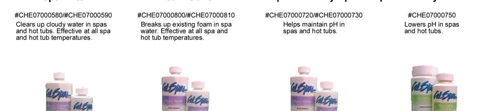

76 Appendix Cal Spas Chemicals Page Inground Spa Owner's Manual
77 2006 Warranty Information Appendix See your Cal Spas dealer for a copy of the applicable warranty, details, and any questions you may have regarding the warranty coverage on your spa. Warranty Limitations The 2006 Limited Warranty is void if the spa has been subject to negligence, alteration, misuse, abuse, repairs by non-c.a.i. authorized representatives, incorrect electrical installation, acts of God and any other cases beyond the control of C.A.I. Examples of common acts invalidating this warranty include, but are not limited to: Use of spa in a non-residential application. Scratches caused by normal use. Operation of spas water temperature out of the normal operating range of 32 F (0 C) to 118 F (47.8 C). Damage caused by incorrect water level (low, overflow, etc.). Damage caused by extreme weather conditions (hot, cold, etc.). Damage caused by dirt, sand and calcium. Damage caused by clogged filter cartridges. See filter cleaning recommendations in this Owner s Manual. Damage caused by continued operation of this spa with either a known or an unknown problem. Damage caused by tri-chlor, acids, chlorine tablets, and any other spa chemicals not authorized by C.A.I. Damage caused by improper water chemistry. (High levels of chlorine, bromine, calcium, ph and other excessive chemical levels.) Damage caused by direct sunlight. Spas should always be covered when not in use. Damage caused as a result of failure to follow operating instructions as defined within this Owner s Manual. Damage caused by incorrect electrical installation, electrical brownout, voltage spikes, or operation of spa out of voltage range by more than ±10%. Spas improperly installed in-ground or placed on non-approved surfaces. The Limited Warranty applies only to spas normally used for personal, family or household purposes. Warranty Exclusions Replaceable service items such as filters, pump seals, light bulbs, ozonator cartridge, pillows, jet inserts, spa covers, and filter covers are specifically excluded from the limited warranty. Spa covers and stereo systems are delivered with their own manufacturer s warranty. For more info, please see their warranties in the owner s information package that was delivered with your spa for more information. Customer Service For customer service, contact the authorized selling dealer immediately. If you need additional information and assistance, please contact the C.A.I. Customer Relations Department at 1462 East Ninth Street, Pomona, CA 91766, or call Inground Spa Owner's Manual Page 73
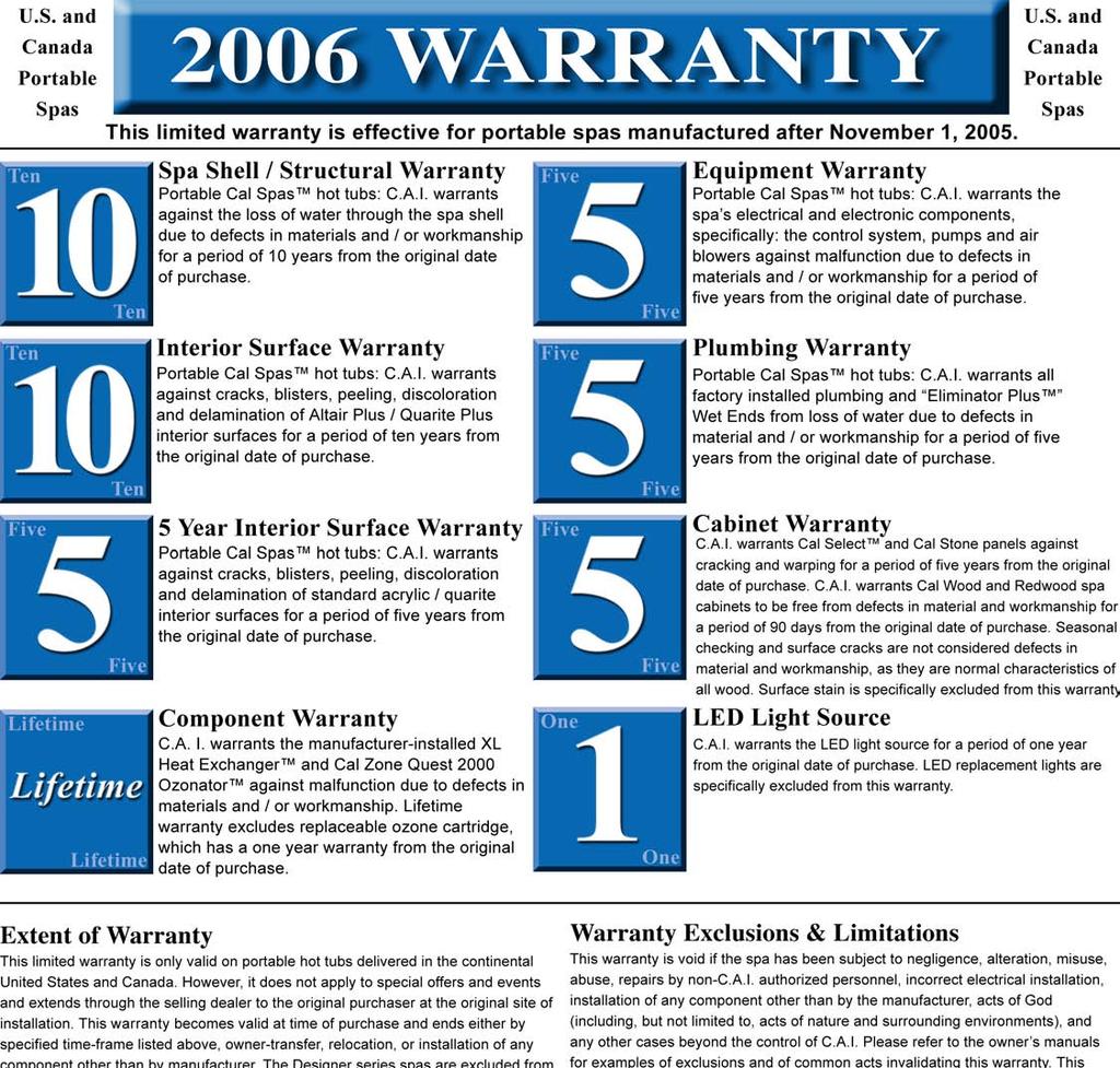
78
2005 Spa Pre-Delivery Guide
 $3.00 2005 Spa Pre-Delivery Guide The guide to making your new Cal Spa installation easy Due to continuous improvement programs, all models, operation, and/or specifications are subject to change without
C.A.I. Customer Service Department 1462 East Ninth Street Pomona, CA Toll Free: CAL-SPAS Fax:
 12/16/2005 CONTACT INFORMATION For customer service, please contact your authorized dealer immediately. If you need additional information and/or assistance, please contact: C.A.I. Customer Service Department
Smart JVA Module WARNING. For use with AquaLink RS systems with rev R firmware or newer.
 INstallation and OPERATION Manual Smart JVA Module For use with AquaLink RS systems with rev R firmware or newer. H0370200 Rev C FOR YOUR SAFETY - This product must be installed and serviced by a contractor
LTR , Rev. A 1/28/08
 1/28/08 Read This First! Important Safety Instructions.............. 3 Basic Spa Information.................... 3 Preparing for Your New Spa In-Ground Spa Installation Checklist........ 5 Planning the
LTR , Rev. E 9/26/08
 9/26/08 Read This First! Important Safety Instructions... 1 Basic Spa Information... 1 Preparing for Your New Portable Spa Planning the Best Location.... 3 Preparing a Good Foundation... 3 120 Volt Electrical
PRE-PURCHASE DECISIONS...1 BEFORE DELIVERY...1
 Table of Contents PRE-PURCHASE DECISIONS...1 BEFORE DELIVERY...1 Typical Installation Site...1 SITE ACCESS...2 COVER...2 ELECTRICAL HOOK UP...3 LOAD SHARING...3 ELECTRICAL REQUIREMENTS...4 North American...4
Spas that free your mind.
 Spas that free your mind. SPECIAL CODE COLORS PMS 1235 PMS 274 PMS 300 PMS 306 110-120V 60Hz 1200W Read this manual before operating 1 IMPORTANT SAFETY INSTRUCTIONS When using this electrical equipment,
WARNING FOR YOUR SAFETY
 ! OWNER S MANUAL Power Alert AquaLink TRI Controller H0389100 REV A WARNING FOR YOUR SAFETY - This product must be installed and serviced by a licensed electrician in accordance with AS/NZ 3000-2007 and
Spas that free your mind.
 Spas that free your mind. 110-120V 60Hz 1200W Read this manual before operating 1 IMPORTANT SAFETY INSTRUCTIONS When using this electrical equipment, basic safety precautions should always be followed,
Life Smart Spas Frequently Asked Questions
 Customer Service (888) 961-7727, ahsservice@watkinsmfg.com Life Smart Spas Frequently Asked Questions What makes Lifesmart Spas different from other spas? Lifesmart spas are rotationally molded. This manufacturing
LOGO INSTRUCTION MANUAL THE SYMBOL FOR QUALITY AND VALUE
 LOGO INSTRUCTION MANUAL THE SYMBOL FOR QUALITY AND VALUE CONGRATULATIONS!!! Your Nordic Hot Tub represents an innovative and unparalleled Hot Tub design, with unmatched quality, features and value. We
2003 Owner s Manual. USA and Canada
 2003 Owner s Manual USA and Canada Pneumatic Series 1100 Electronic Series 2300 Electronic Series 5000 Electronic Series 7000 Electronic Series 9000 Electronic Series Duplication without written consent
2004 Owner s Manual. USA and Canada
 2004 Owner s Manual USA and Canada Duplication without written consent is strictly prohibited. This Owner s Manual is for spas manufactured after January 1, 2004 Due to continuous improvement program,
OWNER S MANUAL ALL 110/120 VOLT PLUG & PLAY SPAS
 OWNER S MANUAL ALL 110/120 VOLT PLUG & PLAY SPAS TABLE OF CONTENTS INTRODUCTION TITLE Page 1. Table of Contents 2 2. Owners Record 3 3. Planning a Location 4 4. A Good Foundation 5 Placing the Hot Tub
Arcadia Spas User Manual
 Arcadia Spas User Manual Dear Spa Buyer, Congratulations on your purchase of a new Arcadia Spa. You now possess the ultimate passport to tranquility a miniature vacation at home, ready and waiting for
Life Smart Spas Frequently Asked Questions LS600DX
 Customer Service (888) 961-7727, ahsservice@watkinsmfg.com Life Smart Spas Frequently Asked Questions LS600DX What makes Lifesmart Spas different from other spas? Lifesmart spas are rotationally molded.
Vortex Spas User Manual
 Vortex Spas User Manual Dear Spa Buyer, Congratulations on your purchase of a new Vortex Spa. You now possess the ultimate passport to tranquility a miniature vacation at home, ready and waiting for you
2004 Owner s Manual. International Electronic Series 2305 Electronic Series 5005 Electronic Series 7005 Electronic Series 9005 Electronic Series
 2004 Owner s Manual International 1505 Electronic Series 2305 Electronic Series 5005 Electronic Series 7005 Electronic Series 9005 Electronic Series LTR17000992 Duplication without written consent is strictly
Hot Tub Installation & Maintenance User Manual
 Hot Tub Installation & Maintenance User Manual HotPriceTubs 6 Guiseley Way Stockton On Tees TS160RF wwwhotpricetubs.com NOTE Because different control systems have various features and options, this manual
D E L U X E S E R I E S. Your Hot Tub Pre-Delivery Guide D E L U X E
 Your Hot Tub Pre-Delivery Guide live better feel better D E L U X E Service Center divinehottubsdeluxe.com Toll Free 1-877-483-1606 customerservice @ divinehottubsdeluxe.com divine hot tubs DLX pre-delivery,
SPA WORLD. Pre- delivery Guide
 SPA WORLD Pre- delivery Guide HELLO! This document is designed to provide all the information you need to ensure the smooth delivery and installation of your spa or swim spa. Please read it carefully and
OWNERS GUIDE. to Years of Enjoyment in your TubLicious Hot Tub. TubLicious Street, Langley, British Columbia, V2Y 1N1
 OWNERS GUIDE to Years of Enjoyment in your TubLicious Hot Tub TubLicious 6315 202 Street, Langley, British Columbia, V2Y 1N1 www.tublicious.com Contents 2 Important Safety Instructions Page 3 Read and
MANUAL
 OWNER S MANUAL www.silhouettehottubs.com 2 CONTENTS: Important safety instructions... Page 3 Preparation and set-up for your new spa... Page 4 Electrical requirements... Page 4 Start-up instructions...
Bulletin Swimming pool, hot tub and spa installations Rules , , , , , and
 Bulletin 68-7-11 Swimming pool, hot tub and spa installations Rules 68-000, 68-056, 68-058, 68-064, 68-068, 68-302 and 68-404 Scope (1) Swimming pools - general (2) Grounding & bonding (a) Bonding for
TABLE OF CONTENTS. 3. Important Safety Instructions. 6. Surface and Pad Requirements. 7. Electrical Requirements. 8. Electrical Connections
 INTRODUCTION The spa that you have purchased is one of the very best available, and incorporates features designed to assure long, enjoyable and healthful use if properly operated and maintained. The following
Your Hot Tub Pre-Delivery Guide
 Your Hot Tub Pre-Delivery Guide live better feel better D E L U X E Service Center divinehottubsdeluxe.com Toll Free 1-877-483-1606 customerservice @ divinehottubsdeluxe.com D E LU X E S E R I E S divine
Spa Start Up & Maintenance
 Spa Start Up & Maintenance Your spa or hot tub is an investment in relaxation. Follow these simple steps for maximum enjoyment! Quality We offer a complete variety of products to support both of our chlorinating
BRILLIANT WONDERS LED BUBBLERS INSTALLATION INSTRUCTIONS & PRODUCT MANUAL CMP SERIES
 BRILLIANT WONDERS LED BUBBLERS INSTALLATION INSTRUCTIONS & PRODUCT MANUAL CMP 25503 SERIES TABLE OF CONTENTS A. PRODUCT OVERVIEW A.1 SPECIFICATIONS A. PRODUCT OVERVIEW... 3 A.1 Specifications A.2 Packing
Jacuzzi. J-CQ420 Cartridge Filter Installation and Operating Instructions
 Jacuzzi J-CQ420 Cartridge Filter Installation and Operating Instructions IMPORTANT SAFETY PRECAUTIONS ATTENTION INSTALLER: This guide contains important information about the installation, operation and
Pool Inspection. Your Street San Diego, California Prepared for: Your Name Prepared by: Priority Inspection Service
 Pool Inspection Your Street San Diego, California 92106 Prepared for: Your Name Prepared by: Page 1 of 10 Table of Contents Standards of Practice 2 Definitions 3 General Information 3 General Pool Information
Part No B (01-00)
") Part No. 3-85-1167B (01-00) INTRODUCTION The spa that you have purchased is one of the very best available, and incorporates features designed to assure long, enjoyable and healthful use if properly operated
Part No. 3-85-1167B (01-00) INTRODUCTION The spa that you have purchased is one of the very best available, and incorporates features designed to assure long, enjoyable and healthful use if properly operated
OC Hot Tubs Owner s Manual
 OC Hot Tubs Owner s Manual 2018 OC Hot Tubs www.ochottubsinfo.com 7/16/18 Important Safety Instructions...1 Basic Spa Information....2 Preparing for Your New Portable Spa. 3 Pre-Delivery Checklist....3
Swimming Pool Requirements
 Swimming Pool Requirements 8040 S. 6th Street Oak Creek, WI 53154 (414) 766-7000 www.oakcreekwi.org Revised: August 8. 2017 PERMITS A permit from the Inspection Department is required prior to putting
Installation of Your SprayMaster System
 Installation of Your SprayMaster System 1. At the installation site, remove all equipment from the corrugated box and the polyethylene drum and replace the drum lid. Check the picture to identify each
SPORT SERIES CLX SPORT TLX SPORT RLX SPORT SLX SPORT
 www.freeflowspas.com OWNER S MANUAL NOVEMBER 1, 2008 PREMIER SERIES ACCENT CROSSFIRE LEGEND PASSPORT SOLSTICE EXCURSION SPORT SERIES CLX SPORT TLX SPORT RLX SPORT SLX SPORT TABLE OF CONTENTS Page Table
UHS. Spa Owner s Manual. PN Rev M Domestic
 UHS Spa Owner s Manual 1 PN 378100-1 Rev M Domestic OWNER S INFORMATION DEALER Company Address Phone E-mail INSTALLER Company Address Phone SPA Model (see below) Serial Number (see below) Color Date of
The Perfect Choice. OWNER S MANUAL DECEMBER 1, Fusion Series. Tropic Azure. Tristar. Opal CAUTION
 The Perfect Choice www.freeflowspas.com OWNER S MANUAL DECEMBER 1, 2009 Fusion Series Tropic Azure Tristar Opal CAUTION DO NOT OPERATE SPA BEFORE READING THIS MANUAL Failure to read this manual & follow
SWIMMING POOL REQUIREMENTS
 PERMITS A permit from the Inspection Department is required prior to putting up a permanent pool. A permit is required for permanent pools, such as the following: SWIMMING POOL REQUIREMENTS The pool is
Step-by-Step Planning Guide
 B A C K Y A R D P L A N N I N G G U I D E Step-by-Step Planning Guide Whether you are considering purchasing a Michael Phelps Signature Swim Spa by Master Spas, or can t wait for yours to be delivered,
Check with local zoning official for property line distance requirements.
 RESIDENTIAL POOL PLAN SUBMITTAL GUIDELINES The following guidelines are intended to assist municipal residents with the permit acquisition process with regard to pools, spas and hot tubs for single family
Your spa and the water
 Spa Care Guide There are numerous types of spas out there. Some spas are small, others are large, some have several jets, and others have few. Spas can be made from an assortment of materials, including
City of Crystal Lake Community Development Department
 City of Crystal Lake Community Development Department 100 W. Woodstock Street Crystal Lake, IL 60014 www.crystallake.org Phone (815) 356-3605 Fax (815) 479-1647 building@crystallake.org ABOVE GROUND SWIMMING
User Manual: Ozone Swim 1000, 2000 and 3000 Series
 User Manual: Ozone Swim 1000, 2000 and 3000 Series P a g e 1 15 Important Safety Information This manual contains important information about the operation and safe use of this product. READ AND FOLLOW
Note: The serial number/identification label is located within the equipment compartment and skimmer housing.
 Spa OWNER S MANUAL Model: Serial Number: Date Installed: Dealer: Address: Telephone: Note: The serial number/identification label is located within the equipment compartment and skimmer housing. Model
Swimming Pools, Hot Tubs and Spas
 OLATHE FIRE DEPARTMENT BUILDING CODES 1225 S. Hamilton Circle Olathe, KS 66061 / Main: (913) 971-7900 / Fax: (913) 971-9812 Swimming Pools, Hot Tubs and Spas Definitions: Swimming Pool- Any structure intended
Model PSI Compressor with 3-Gallon Air Tank 12VDC
 Model 6350 150 PSI Compressor with 3-Gallon Air Tank 12VDC IMPORTANT: It is essential that you and any other operator of this product read and understandd the contents of this manual before installing
RESIDENTIAL SWIMMING POOLS AND SPAS A GUIDE FOR HOMEOWNERS
 RESIDENTIAL SWIMMING POOLS AND SPAS A GUIDE FOR HOMEOWNERS City of Redding 777 Cypress Avenue Redding CA 96001 Telephone: (530) 225-4013 FAX: (530) 225-4360 A Swimming Pool is any body of water 18 inches
2 GALLON TWIN STACK AIR COMPRESSOR W/ HOSE REEL
 2 GALLON TWIN STACK AIR COMPRESSOR W/ HOSE REEL Model: 52024 CALIFORNIA PROPOSITION 65 WARNING: You can create dust when you cut, sand, drill or grind materials such as wood, paint, metal, concrete, cement,
S P A C A R E G U I D E
 SPA CARE GUIDE There are many reasons why you own and use your spa: Relaxation. Therapy. Entertainment. Comfort. No matter why you use your spa, when you are using it, you are relaxing by submerging yourself
Sunbrite LTC Large Underwater Pool Lights
 Sunbrite LTC Large Underwater Pool Lights O W N E R S M A N U A L 3050 0997 ASB INSTALLATION, OPERATION & PARTS This manual should be furnished to the end user of this light; its use will reduce service
Crossover Collection Owner s Manual
 Crossover Collection Owner s Manual 1 PN 378107Rev I Euro OWNER S INFORMATION DEALER Company Address Phone E-mail INSTALLER Company Address Phone SPA Model (see below) Serial Number (see below) Color Date
Bath with Airjets HOMEOWNERS GUIDE P50045-G5, P50047-G5, P50049-G5, P50052-G D
 P50045-G5, P50047-G5, P50049-G5, P50052-G5 2014 1 of 16 Kallista IMPORTANT SAFETY INSTRUCTIONS READ AND FOLLOW ALL INSTRUCTIONS SAVE THESE INSTRUCTIONS INSTRUCTIONS PERTAINING TO A RISK OF FIRE, ELECTRICAL
Installation and Maintenance Manual. ECO Filtration Unit with 6-way-Top-Mount-Valve. Art. Nr
 Installation and Maintenance Manual ECO Filtration Unit with 6-way-Top-Mount-Valve Art. Nr. 300100 300101 300102 Important Details: - Using of this filtration unit for swimming pools and its guard band
BRILLIANT WONDERS LED BUBBLERS INSTALLATION INSTRUCTIONS CMP SERIES. Brilliant Wonders LED BUBBLERS
 R BRILLIANT WONDERS LED BUBBLERS INSTALLATION INSTRUCTIONS CMP 25503 SERIES Brilliant Wonders LED BUBBLERS TABLE OF CONTENTS 1. Product Overview....3 1.1 Specifications. 3 1.2 Packing List...3 2. System
SPECIFICATIONS Type: Twin stack, single phase Tank: 4 gallon Air Output: PSI; PSI Max PSI: 125 PSI HP: 1.
 2 GALLON TWIN STACK AIR COMPRESSOR Model: 9526 DO NOT RETURN TO STORE. Please CALL 800-348-5004 for parts and service. CALIFORNIA PROPOSITION 65 WARNING: You can create dust when you cut, sand, drill or
LTR , Rev. F 10/19/15
 10/19/15 Important Safety Instructions....... 1 Preparing for Your New Portable Spa. 2 Pre-Delivery Checklist.................. 2 Planning the Best Location.............. 2 Preparing a Good Foundation............
Installation, Operation and Maintenance Instructions for Electronically Controlled Pressurisation Units
 Installation, Operation and Maintenance Instructions for Electronically Controlled Pressurisation Units Models: EPS Single Pump EPT Twin Pump EPS-HP EPT-HP Single Pump High Pressure Twin Pump High Pressure
Jacuzzi. J-SS40 Salt System Installation and Operating Instructions
 Jacuzzi J-SS40 Salt System Installation and Operating Instructions IMPORTANT SAFETY INSTRUCTIONS WARNING: Before installing this product. Read and follow all warning notices and instructions accompanying
Owner s Manual5HH. PN Rev E
 Owner s Manual5HH 1 PN 378105 Rev E OWNER S INFORMATION PN DEALER Company Address Phone E-mail INSTALLER Company Address Phone SPA Model Serial Number (see below) Color Date of Delivery Locate the white
1020 Industrial Drive, Orlinda, TN fax
 Operation Manual Tank Distribution System A-UPT Series 615-654-4441 sales@specialtyh2o.com 615-654-4449 fax TABLE OF CONTENTS Section 1 GENERAL 1.2 Warnings and Cautions... 1 1.2 Theory of Operation...
WAKE COUNTY POOL PERMIT PRE-SEASON AUDIT 2014
 A DEPTH MARKINGS There are Depth Markings on and around a. On the vertical wall of the pool and on this pool that are at least 4 inches high; in contrasting color to the background; of a slip resistant
AMITY TWP POOL REQUIREMENTS
 AMITY TWP POOL REQUIREMENTS Construction In-ground, Above-ground and Storable pools and Spas shall be designed and constructed in conformance with International Swimming Pool & Spa Code (ISPSC) Location
ROUND ASSEMBLY. Positioning
 ROUND ASSEMBLY Positioning To ensure maximum enjoyment and efficiency, consider the following steps when selecting the desired location of you pool. Select a location that receives maximum sunlight for
PARADISE SERIES O W N E R S M A N U A L
 PARADISE SERIES 2 0 1 6 O W N E R S M A N U A L WELCOME Watkins Manufacturing Corporation congratulates you on your decision to enjoy the finest spa available... Welcome to the growing family of Caldera
Hot Tub Pre-Delivery Guide
 Hot Tub Pre-Delivery Guide To prepare for the delivery of your hot tub, make sure the delivery path is clear and no obstructions are present. Obstacles such as overhanging tree limbs, awnings, protruding
Owner s Manual WELCOME DATE PURCHASED: DATE INSTALLED: DEALER: ADDRESS: TELEPHONE: SPA MODEL/SERIAL NUMBER: COVER SERIAL NUMBER:
 WELCOME Watkins Manufacturing Corporation congratulates you on your decision to enjoy the finest spa available... Welcome to the growing family of Caldera spa owners. Owner s Manual This Owner s Manual
This manual covers your new TidalFit Rev
 This manual covers your new TidalFit Rev TABLE OF CONTENTS Congratulations... 1 Important Safety Instructions... 3 Line Drawing Key... 7 TidalFit Configuration and Water Capacities... 8 Electrical Requirements
accidents which arise due to non-observance of these instructions and the safety information herein.
 3 GALLON PANCAKE COMPRESSOR Model: 50959 CALIFORNIA PROPOSITION 65 WARNING: You can create dust when you cut, sand, drill or grind materials such as wood, paint, metal, concrete, cement, or other masonry.
Aquavar SOLO 2 Frequently Asked Questions
 Aquavar SOLO 2 Frequently Asked Questions How do I size the Aquavar SOLO 2 for the appropriate pump/motor combination? Can I use a 208 Volt motor? Can I run the Aquavar SOLO 2 up to 80HZ? What are the
POOL AND HOT TUB/SPA REGULATIONS A BUILDING PERMIT IS REQUIRED BEFORE THE INSTALLATION OF A POOL.
 CITY OF NEENAH Department of Community Development (Inspection Department) 211 Walnut Street Phone (920) 886-6130 website: www.ci.neenah.wi.us POOL AND HOT TUB/SPA REGULATIONS A BUILDING PERMIT IS REQUIRED
AIR COMPRESSOR OPERATING INSTRUCTION AND PARTS LIST
 AIR COMPRESSOR OPERATING INSTRUCTION AND PARTS LIST OIL-LESS TYPE IMPORTANT: PLEASE READ CAREFULLY BEFORE STARTING OPERATIONS. THE CONTENTS ARE FOR GENERAL INFORMATION OF ALL THE SIMILAR MODELS. Record
Sand Dollar Filter Owner s Manual IMPORTANT SAFETY INSTRUCTIONS SAVE THESE INSTRUCTIONS READ AND FOLLOW ALL INSTRUCTIONS SAVE THESE INSTRUCTIONS
 SAVE THESE INSTRUCTIONS Pentair Pool Products P/N 99223000 12 Rev. E 2-22-02 Sand Dollar Filter Owner s Manual IMPORTANT SAFETY INSTRUCTIONS READ AND FOLLOW ALL INSTRUCTIONS SAVE THESE INSTRUCTIONS Table
Nottingham Township 909 Sugar Run Road Eighty Four PA (724) Fax (724)
 Fax (724)") Nottingham Township 909 Sugar Run Road Eighty Four PA 15330 (724) 348-5622 Fax (724) 348-8822 Swimming Pool Application Requirements SWIMMING POOL Any structure intended for swimming or recreational bathing
Nottingham Township 909 Sugar Run Road Eighty Four PA 15330 (724) 348-5622 Fax (724) 348-8822 Swimming Pool Application Requirements SWIMMING POOL Any structure intended for swimming or recreational bathing
Signature Spas & Pools Inc
 Dear Spa/Pool Owner, Hopefully you and your family enjoyed the Summer. We completed most of our expansion into Pools as well as Hot Tubs. We have implemented Pool Services such as Opening, Weekly Maintenance,
PERMANENT POOLS. Location
 Community Development Department 211 Walnut Street - PO Box 426 Neenah, WI 54957-0426 Phone: (920) 886-6130 Fax: (920) 886-6129 Web site: www.ci.neenah.wi.us PERMANENT POOLS A pool is any man-made structure,
IMPORTANT SAFETY INSTRUCTIONS READ AND FOLLOW ALL INSTRUCTIONS SAVE THESE INSTRUCTIONS
 Spa Owner s Manual www.dreammakerspas.com This Manual Contains IMPORTANT SAFETY INSTRUCTIONS READ AND FOLLOW ALL INSTRUCTIONS SAVE THESE INSTRUCTIONS OWNER S INFORMATION DEALER Company Address Phone E-mail
AURA HOT TUBS OWNER S MANUAL
 0 O W N E R S M A N U A L AURA HOT TUBS OWNER S MANUAL We sincerely hope your spa life is a pleasant experience. If problems should arise, contact AURA at any of the following: Email: contact@aurahottubs.com
MODEL NUMBER: PSI AIR SOURCE KIT 200 PSI Compressor on 2.0 Gallon 200 PSI Air Tank
 IMPORTANT SAFETY INSTRUCTIONS CAUTION - To reduce risk of electrical shock or Electrocution: MODEL NUMBER: 20008 200 PSI AIR SOURCE KIT 200 PSI Compressor on 2.0 Gallon 200 PSI Air Tank IMPORTANT: It is
RESIDENTIAL SWIMMING POOL REQUIREMENTS
 CITY OF GRANDVIEW / BUILDING SERVICES 1200 MAIN STREET, GRANDVIEW, MO 64030 PHONE: (816) 316-4817 FAX: (816) 316-4809 WWW.GRANDVIEW.ORG RESIDENTIAL SWIMMING POOL REQUIREMENTS Community Development Department
Blue Whale Spa :- Site Preparation and Delivery
 Pre-Delivery Instructions Please take the time to read this information carefully, as it will provide you with the information you will need to ensure the safe, secure, and timely installation of your
SWIMMING POOL PERMITS ARE ABOUT HEALTH AND SAFETY
 SWIMMING POOL PERMITS ARE ABOUT HEALTH AND SAFETY Swimming Pool Booklet Washington County, Maryland Published 2004 Revised 03/10/05 Revised 02/10/06 Department of Permits & Inspections 80 West Baltimore
OWNER S MANUAL. Classic. Series. SpaDepot.com M-F 6am - 5pm Pacific Time Order Supplies Online
 OWNER S MANUAL Classic Series SpaDepot.com 1-800-823-3638 M-F 6am - 5pm Pacific Time Order Supplies Online belize-spas-owners-manual.pdf (rev. 10-24-17) Contents Important Safety Instructions and Warnings...
DUAL SUCTION OUTLETS
 ISWG1061 Rev A DUAL SUCTION OUTLETS Contents Product Specific Warnings 2 Recommended system specifications... 5 Installation.... 6 Replacement Parts... 6 Owner s Manual Model No.: WG1061HF2PAK2 and WG1061LV2PAK2
IntelliChlor Power Center (For use with IntelliChlor model IC60, IC40 and IC20)
") IntelliChlor Power Center (For use with IntelliChlor model IC60, IC40 and IC20) Patents pending Certified to NSF/ANSI 50 Installation and User s Guide IMPORTANT SAFETY INSTRUCTIONS READ AND FOLLOW ALL
IntelliChlor Power Center (For use with IntelliChlor model IC60, IC40 and IC20) Patents pending Certified to NSF/ANSI 50 Installation and User s Guide IMPORTANT SAFETY INSTRUCTIONS READ AND FOLLOW ALL
SWIMMING POOL, SPAS, HOT TUB REQUIREMENTS AND GUIDELINES (Updated 3/2018)
") SWIMMING POOL, SPAS, HOT TUB REQUIREMENTS AND GUIDELINES (Updated 3/2018) POOL/SPA CHECKLIST Submittal of two (2) sets of plans is required for permit issuance. Obtain approval from the Planning/Zoning
SWIMMING POOL, SPAS, HOT TUB REQUIREMENTS AND GUIDELINES (Updated 3/2018) POOL/SPA CHECKLIST Submittal of two (2) sets of plans is required for permit issuance. Obtain approval from the Planning/Zoning
Owner s Manual. Moorea Hawaiian Martinique Kauai
 Paradise Series Owner s Manual Moorea Hawaiian Martinique Kauai WELCOME Watkins Manufacturing Corporation congratulates you on your decision to enjoy the finest spa available... Welcome to the growing
Signature Spas & Pools
 EVERY 3 MONTHS 1. POWER DOWN SPA BY EITHER PULLING QUICK DISCONNECT NEAR SPA OR BY SHUTTING OFF MAIN BREAKER. 2. DRAIN SPA & CLEAN WITH CITRABRIGHT SPRAY CLEANER, USE NON- ABRASIVE SCRUBBER FOR HARD TO
This manual covers your new TidalFit Rev
 This manual covers your new TidalFit Rev Table of Contents Congratulations... 1 Important Safety Instructions... 3 TidalFit Specifications... 7 Electrical Requirements and Installation... 8 Electrical
PROPORTIONING VALVE. Model 150 INSTRUCTION MANUAL. March 2017 IMS Company Stafford Road
 PROPORTIONING VALVE Model 150 INSTRUCTION MANUAL March 2017 IMS Company 10373 Stafford Road Telephone: (440) 543-1615 Fax: (440) 543-1069 Email: sales@imscompany.com 1 Introduction IMS Company reserves
Paradise Series. Owner s Manual. Moorea. Hawaiian Martinique. Kauai
 Paradise Series Owner s Manual Moorea Hawaiian Martinique Kauai WELCOME Watkins Manufacturing Corporation congratulates you on your decision to enjoy the finest spa available... Welcome to the growing
This manual covers your new 2009 TidalFit
 Part # (11-0096-11) This manual covers your new 2009 TidalFit TABLE OF CONTENTS Congratulations... Safety Warnings... Line Drawing Key... TidalFit Configuration and Water Capacities... Electrical Requirements
Gerber Sabre 404 and 408 Installation Instructions
 1 TITLE: Gerber FastFact # Supplied by: Last Modified: Summary: Gerber Sabre 404 and 408 Installation Instructions 5002 Gerber Service November 13, 2001 This document provides the installation and set-up
MODEL NUMBER: M20005 AIR SOURCE KIT. 30% Duty Compressor on. 2.0 Gallon Air Tank SAVE THIS MANUAL FOR FUTURE REFERENCE
 MODEL NUMBER: M20005 AIR SOURCE KIT 30% Duty Compressor on 2.0 Gallon Air Tank SAVE THIS MANUAL FOR FUTURE REFERENCE USER MANUAL IMPORTANT SAFETY INSTRUCTIONS CAUTION - To reduce risk of electrical shock
AIR COMPRESSOR. Failure to follow all instructions as listed below may result in electrical shock, fire, and/or serious personal injury.
 2 GALLON AIR COMPRESSOR Model: 7517 DO NOT RETURN TO STORE. Please CALL 800-348-5004 for parts and service. CALIFORNIA PROPOSITION 65 WARNING: You can create dust when you cut, sand, drill or grind materials
DEH Instructions. Three-Phase, Platform-Mounted Distribution Transformers
 g DEH 40050 Instructions Three-Phase, Platform-Mounted Distribution Transformers Introduction The equipment covered by these instructions should be operated and serviced only by competent technicians familiar
Swimming Pool Requirements Packet
 Plot Plans shall indicate the following: Drawn to an appropriate scale with pool depths shown and dimensions to other structures Have an engineer address any surcharge loads on the pool or from the pool
To purchase replacement parts and accessories, or to obtain technical assistance, visit:
 IMPORTANT Read this guide and follow all instructions carefully before assembling or using this product. To purchase replacement parts and accessories, or to obtain technical assistance, visit: www.splasharoundpools.com
CARTRIDGE FILTERS. Models: CF50, CF75, CF100, CF150,
 CARTRIDGE FILTERS Models: CF50, CF75, CF00, CF50, The installation of this product should be carried out by a qualified pool technician, following the installation instructions provided in this manual.
ARCHITECTURAL GUIDELINES ONE-PIECE COMMERCIAL
 ARCHITECTURAL GUIDELINES ONE-PIECE COMMERCIAL Architect Guidelines for SwimEx Installation of 500OT DW, 500OT, and 400OT General Layout Call SwimEx at 800-877-7946 to receive AutoCad Drawings of the SwimEx
IMPORTANT SAFETY INSTRUCTIONS READ AND FOLLOW ALL INSTRUCTIONS SAVE THESE INSTRUCTIONS
 Commander Cartridge Filter Operating Procedures IMPORTANT SAFETY INSTRUCTIONS READ AND FOLLOW ALL INSTRUCTIONS SAVE THESE INSTRUCTIONS Table of Contents SECTION I. FILTER INSTALLATION... 1 SECTION II.