COUNTER CURRENT UNIT. Instruction Manual
|
|
|
- Lydia Bradford
- 5 years ago
- Views:
Transcription

1 COUNTER CURRENT UNIT Instruction Manual 1
2 Introduction: Congratulations on your purchase of a new Certikin counter current swimming unit. This unit has been developed and built by qualified personnel especially for swimming pool use. It is your responsibility to ensure that all recommendations, as far as transport, installation, connection, maintenance and repair of the unit, as detailed in this manual are strictly adhered to. Both air and water volume output can be controlled from the directional inlet on the face plate assembly. The top of the range auto prime pump enables the unit to achieve maximum output with minimum noise. Take the time to read the installation and commissioning manual carefully in order to ensure that you get the most from your counter current swimming unit. The counter current swimming unit guarantee is only valid if all the recommendations contained in this manual have been followed. Certikin International will not be liable for any malfunction resulting from incorrect handling or incorrect installation. 2
3 Nozzle assembly: General instructions Should be positioned at more than 300mm from the minimum water level (fig 1) All connections should be vertical The inlet end of the air entry tube should be situated above the water level of the pool The PVC pipes and connections used to connect the pump to the nozzle should be assembled according to the indications in the Plumbing Assembly Chapter. All the technical instructions provided should be followed carefully. The safety and the efficiency of the counter-flow current unit are only guaranteed if the commissioning and installation instructions are respected. Kit contents Part Code Description C - Concrete PF - Liner L - Prefabricated Counter Current Jet (Front Part) Counter Current Jet (Housing) AQP301 / AQP303 Pump GP200BV Ball Valve GP degree Elbow GP degree Elbow Crystal Hose Adhesive Seal Air Tube CBCC-M / CBCC-T Electric Control Box Screw M6 x Screw M6 x Screw 4.8 x Housing assembly 4 Assembly instructions For concrete pools (C)(fig 2) Locate the housing as shown in fig 2. ensuring that the connections are vertically aligned. For panelled pools (L and DL)(fig 3) Locate the fastening flange, ensuring that the recommended distance above the water level and the vertical alignment of the connections are respected. Trace the position of the external crown of the fastening flange Cut the panel following the line traced around the external crown of the flange Place the housing on the panel and trace the position of the 8 holes Fix the housing onto the panel using the 4.8 x 25 screws. 3
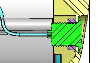
4 For Polyester Pools or liner pools (PF)(fig 4) Locate the fastening flange, ensuring that the recommended distance above the water level and the vertical alignment of the connections are respected. Using the fastening flange trace the position of the screws and the internal crown Make the 14 fixing holes on the panel/liner and cut out following the interior flange diameter Flange assembly 2 (Panelled and liner pools PF & L) Clean all surfaces of the flange and housing onto which the seal will be attached Stick the seals onto the surfaces If the pool is a liner pool position the liner and fill the pool to just below the housing Fix the flange onto the housing using 16 M6 x 24 screws. Front part assembly 1 Fix the air tube (Ø5mm, length 3000mm) on the push button keeping it on the outside of the casing (fig 5). Check that air flows through the tube when the push button is operated Unscrew the gland seal completely in order to pass the air tube through it Ensure that the air tube is pulled as far through the clear hose as possible Fix the air-hose connection (ready assembled onto the housing) onto the front part. Screw the front part onto the housing taking care not crush the air connection or the air tube Attention: The air inlet tube MUST be ABOVE the pool water level and the inlet must be protected from foreign bodies. Connecting counter current jet to the pump IMPORTANT NOTE: If the pump is installed more than 1 metre from the counter current jet the Ø63mm tubes, valves and elbows MUST be replaced by Ø90 mm. Before connecting the counter current unit to the pump the housing and the pump must have been installed as above. Prepare all the PVC tubes After assembly ensure that there are no leaks see (fig 7) Glue the 90/63 and 75/63 reducers(1) onto the rear housing connectors at the rear of the housing (2) Attach the reducers to the ball valves (3) using the PVC pipes (shown in grey on the diagram) Attach the ball valves to the pump (4) using the 90 o and 45 o elbows supplied (ensure the valves are fitted in the right way) fig 8. 4
5 Plumbing assembly To join any parts in PVC please follow the following guidelines: Carefully sandpaper the surfaces to be glued Clean the sanded surfaces with a special PVC degreaser Glue the parts together with a special PVC pressured adhesive Join the parts together - please note that drying time is often short! Electro-pneumatic connection Check that the power supply is correct for the equipment The Electrical box and the push button should never be more than 10m apart. Ensure that the electrical box CANNOT come into contact with water. Follow the specific instructions supplied with the electrical box Connect the air tube to the on/off switch Operation Once the counter current swimming unit is installed check the rotational direction of the pump motor. The air and flow rates can then be regulated, as shown in fig 9. Winterising In case of exceptionally cold weather or hard frosts it is necessary that the front part of the Counter swim unit be disassembled. Unscrew the screws which attach the front part of the housing Disconnect the air tube from the push-button Disconnect the front part of the air inlet tube Put 2 plugs inside the housing inlets Completely empty the pump (see electrical pump for swimming pool/ installation and maintenance manual). 5
6 Fig 1 Counter current positioning Annexes 300mm Fig 2 Concrete swimming pool POOL Fig 3 Panelled + liner POOL Fig 4 Prefabricated or liner pools POOL POOL LINER Figure 1 6

7 Fig 5 Pneumatic Pushbutton Fig 6 Air aspiration Fig 7 Assembly


8 Fig 8 Ball valve Fig 9 Airflow setting Waterflow setting We reserve the right to change all or part of the article or contents of this document, without prior notice. 8
9 9
JET SWIM ELEGANCE 70 INSTALLATION AND USER GUIDE
 JET SWIM ELEGANCE 70 INSTALLATION AND USER GUIDE i Read the instructions 1. Installation mounting By purchaising the ELEGANCE device, you obtained a high-quality product that will help you to enjoy the
Latvin Luxury Shower Panel. Telephone Product Specification. ~ Minimum Working Pressure 1.0 bar ~ Maximum Working Pressure 3.
 Product Specification ~ Minimum Working Pressure 1.0 bar ~ Maximum Working Pressure 3.0 bar Latvin Luxury Shower Panel ~ Fixing Centres 150mm +/- 10mm ~ Outlet size 1/2" Bottom Outlet Always maintain a
INSTALLATION INSTRUCTIONS
 COUNTER-CURRENT SWIMMING Hurricane Turbo Swim Jet INSTALLATION INSTRUCTIONS PACKET NO.1 With a COUNTER-CURRENT SWIMMING device your swimming pool is no longer a simple man-made lake. It becomes the most
Jet Swim Installation instruction
 Jet Swim 2000 Jet Swim 2000 Liner pool 1. Remove the stainless steel front plate and cut out the pool wall according to the hole pattern. The center of the Jet Swim housing must be a minimum of 170 mm
12 Volt Inflator. Operator s Manual. Model: ICC12F, ICC12FC, ICC12FCN, ICC12FCM, ICC12N
 Operator s Manual 12 Volt Inflator Model: ICC12F, ICC12FC, ICC12FCN, ICC12FCM, ICC12N 873 E. Citation Court Boise, Idaho 83716 USA 800-874-5771 www.bon-aireindustries.com Safety Guidelines Assembly Operation
Hydrotherapy Jets System for a Fiberglass Pool
 Page 1 of 5 Parts List 1-50 Flex PVC pipe 2-1 1 / 2 " Ball Valves 4-1/2" 90 degree elbows 4 - Lengths of 1/2" PVC 4 - Jet bodies 4 - Jet nozzles 6 - Female slip/female slip unions 2 - Female slip/fpt union
Poollift Delphin. Version: February, 2015 MANUAL AND OPERATING INSTRUCTIONS
 Poollift Delphin Version: February, 2015 MANUAL AND OPERATING INSTRUCTIONS Content 1. Introduction... 3 2. Technical Specifications... 3 Used materials... 3 3. Installation Instructions... 4 Fastening
AutoChanger Installation & User Guide Issue 2
 1 INDEX Page 1. Introduction... 3 2. AutoChanger Components Guide 4 3. Installation. 5-11 a) Installation Guidelines.. 5 b) Installation Retrofit... 6-11 c) Installation New... 11 4. AutoChanger User Guide
User Manual for the Mars Calibration Bench
 User Manual for the Mars Calibration Bench Fall 2013 Table of Contents Table of Contents Table of Contents... iii Introduction... v Chapter 1: The Mars Calibration Bench... 1 What Is the Mars Calibration
CARTRIDGE FILTERS. Models: CF50, CF75, CF100, CF150,
 CARTRIDGE FILTERS Models: CF50, CF75, CF00, CF50, The installation of this product should be carried out by a qualified pool technician, following the installation instructions provided in this manual.
CONDITIONS OF SALE AND WARRANTY
 CONDITIONS OF SALE AND WARRANTY 1. Read carefully this operator's handbook before operating our C500 corking machine. 2. M.E.P. guarantees his C500 corking machine in case of breakages caused by faulty
OPERATING INSTRUCTIONS MANUAL FOR QACV PNEUMATIC DOSING PUMP
 This operating instructions contains safety information that if ignored can endanger life or result in serious injury. They are indicated by this icon. Use of this pump with radioactive chemicals is forbidden!
INSTALLATION INSTRUCTIONS FOR GRT75-PF-RFS PET FOUNTAIN
 INSTALLATION INSTRUCTIONS FOR GRT75-PF-RFS PET FOUNTAIN Important: Read all instructions and refer to local codes prior to installation. l Local soil conditions may require more gravel for drainage. l
Halsey Taylor Owners Manual 4410 Freeze Resistant Tubular Fountain STOP!
 Halsey Taylor Owners Manual 4410 Freeze Resistant Tubular Fountain STOP! PLEASE READ THE FOLLOWING INFORMATION. ITALLATION ITRUCTIO FOR THE 4410FR FTN. WITH 97243C SINGLE VALVE CONTROL ASSEMBLY ARE LOCATED
Halsey Taylor Owners Manual STOP!
 Halsey Taylor Owners Manual 4710 Freeze Resistant Floor Mounted Steel Fountain STOP! PLEASE READ THE FOLLOWING INFORMATION. ITALLATION ITRUCTIO FOR THE 4710FR FTN. WITH 97243C SINGLE VALVE CONTROL ASSEMBLY
35 TON HYDRAULIC PUNCH WARNING
 OPERATORS GUIDE REL-35T-PNC 35 TON HYDRAULIC PUNCH NOTICE Sizes, weights and tool specifications listed in this manual are subject to change without notice. Please consult factory for information and updates.
Breather Control V1.4. Installation Manual
 Breather Control V1.4 Installation Manual Installation manual Breather Control 19.05.2017 Valid for: #9771 #10219 Contents V1.4/05.17 1 Intended use and general safety instructions... 2 2 Description...
Manual Actuated Boiler Blowdown Valves
 Manual Actuated Boiler Blowdown Valves Installation and Maintenance Instructions 1. Safety information 2. General product information 3. Installation 4. Operation 5. Maintenance 6. Spare parts p.1 1. Safety
Pressure maintenance valve SDV-P / SDV-P-E
 Translation of the original manual Pressure maintenance valve SDV-P / SDV-P-E Assembly and Operating Manual Superior Clamping and Gripping Imprint Imprint Copyright: This manual remains the copyrighted
2 in. 18 Gauge Brad Nailer. User manual
 8504342 2 in. 18 Gauge Brad Nailer User manual Technical Data Capacity....100pcs Nail length... 15-50mm( 5/8-2 ) Fastener size....18gauge (1.25 1.00mm) Operation pressure 70-110PSI(4.8-7.5bar) Air inlet....1/4
Installation/Care/Use Manual
 Installation/Care/Use Manual EMASM Surface Mount Bottle Filling Station IMPORTANT THIS IS AN INDOOR APPLICATION ONLY! ALL SERVICE TO BE PERFORMED BY AN AUTHORIZED SERVICE PERSONNEL. TOOLS/ITEMS REQUIRED
Product Manual B-Safety ClassicLine & PremiumLine Emergency Eyewash and Eye/Face Wash Equipment
 Product Manual B-Safety ClassicLine & PremiumLine Emergency Eyewash and Eye/Face Wash Equipment 1. Application Emergency eyewash and eye/face wash equipment are prescribed first aid installations for workplaces
POOL ROVER ST POOL CLEANER Installation Instructions
 POOL ROVER ST POOL CLEANER Installation Instructions A. ASSEMBLY FIG 1 - Place the seal over the top of the pool cleaner body and slide it down to the mouth. FIG 2 - Secure the seal beneath the flange
Easy Nest Kits. Installation Suggestions
 Easy Nest Kits Installation Suggestions 2 General Recommendations Hydraulics Vacuum breakers should be installed to prevent siphoning. Flexible connectors should follow FRP tank manufacturers recommendations.
Air Intake Snorkel Kit
 SSV KIT - Air Intake Snorkel Kit Part number (SKU) : 715003733 Product: Side-by-side Project no: 487802499 Instruction Sheet P/N: 487802499 Revision no: Revision date: Item covered: Air Intake Snorkel
170-CG Feed Unit SPONGE-JET USER MANUAL. Sponge-Jet, Inc. (USA) 14 Patterson Lane Newington, NH
 14 Patterson Lane Newington, NH") SPONGE-JET 170-CG Feed Unit USER MANUAL Sponge-Jet, Inc. (USA) 14 Patterson Lane +1-603-610-7950 Newington, NH 03801 www.spongejet.com AUGUST 2014, Sponge-Jet 170-CG User Manual - REV A / DOC: M-MKTG-002ENG
SPONGE-JET 170-CG Feed Unit USER MANUAL Sponge-Jet, Inc. (USA) 14 Patterson Lane +1-603-610-7950 Newington, NH 03801 www.spongejet.com AUGUST 2014, Sponge-Jet 170-CG User Manual - REV A / DOC: M-MKTG-002ENG
Commercial Softeners. Installation, Operation & Maintenance Guide. Manual 002.1
 Commercial Softeners Installation, Operation & Maintenance Guide Manual 002.1 Contents Page 1. Unpacking Instructions 3 2. Installation 3 Pre-installation checks Fitting the bottom distribution system
Pressure Dump Valve Service Kit for Series 2300 Units
 Instruction Sheet Pressure Dump Valve Service Kit for Series 00 Units. Overview The Nordson pressure dump valve is used to relieve hydraulic pressure instantly in Series 00 applicator tanks when the unit
BASIN AND WALL MIXER INSTALLATION INSTRUCTIONS
 BASIN AND WALL MIXER INSTALLATION INSTRUCTIONS IMPORTANT INFORMATION IMPORTANT All tapware and showers to be installed by a licensed plumber and to Australian Standards. Fit tempering and pressure reduction
Installation, Operating, Maintenance and Safety Instructions for. Pressurised water systems for boats
 FLOMAX-SYSTEM DOC532/11 Installation, Operating, Maintenance and Safety Instructions for FLOMAX-SYSTEM Pressurised water systems for boats CW343A FloMax System 12 volt d.c. CW344A FloMax System 24 volt
ETL listed for installations within 5 ft. (1.5M) of outer edge of water
 of outer edge of water") Fiberstars Light Streams Mini Laminar Installation Manual (LSML) 3072091 ETL listed for installations within 5 ft. (1.5M) of outer edge of water 79-15056-00 Rev. A Page 1 of 6 SAVE THESE INSTRUCTIONS!
Fiberstars Light Streams Mini Laminar Installation Manual (LSML) 3072091 ETL listed for installations within 5 ft. (1.5M) of outer edge of water 79-15056-00 Rev. A Page 1 of 6 SAVE THESE INSTRUCTIONS!
ABRASIVE REGULATOR II
 ABRASIVE REGULATOR II 13096 Abrasive Regulator II TABLE OF CONTENTS Contact Information and Customer & Technical Service... 1 1 Introduction... 1 2 Abrasive Regulator... 1 Description:... 1 2.1 Regulator
Duplex Commercial Softeners
 Duplex Commercial Softeners Installation, Operation & Maintenance Guide Manual 003.1 Contents Page 1. Unpacking Instructions 3 2. Installation 4 Pre-installation checks Fitting the bottom distribution
Flexi-pro Aerosol Delivery System (FADS) Manual
 Manual") 603-000-010 Flexi-pro Aerosol Delivery System (FADS) Manual Troubleshooting Troubleshooting Problem Solution Problem Solution About Flexi-pro Aerosol Delivery System is able to adapt to a variety of traditional
603-000-010 Flexi-pro Aerosol Delivery System (FADS) Manual Troubleshooting Troubleshooting Problem Solution Problem Solution About Flexi-pro Aerosol Delivery System is able to adapt to a variety of traditional
PAGE (Rev. A - 06/17)
") Owners Manual Models 4420BF1UDBFR* and 4420BF1LDBFR* Bi-Level Tubular Bottle Filler Fountain with Pet Fountain and Sanitary Freeze Resistant Triple Valve Control Assembly MODEL (LK)4420BF1UDBFR MODEL (LK)4420BF1LDBFR
Owners Manual Models 4420BF1UDBFR* and 4420BF1LDBFR* Bi-Level Tubular Bottle Filler Fountain with Pet Fountain and Sanitary Freeze Resistant Triple Valve Control Assembly MODEL (LK)4420BF1UDBFR MODEL (LK)4420BF1LDBFR
UNITY 2. Uni-DAAMS Manual. Version 1.3 (Changes to Section 1.1) March 2010
 March 2010") UNITY 2 Uni-DAAMS Manual Version 1.3 (Changes to Section 1.1) March 2010 1. Introduction...2 1.1. Installing the DAAMS tube ovens...2 1.2. Swapping between tube types...5 1.3. Changing tube oven o-rings...6
UNITY 2 Uni-DAAMS Manual Version 1.3 (Changes to Section 1.1) March 2010 1. Introduction...2 1.1. Installing the DAAMS tube ovens...2 1.2. Swapping between tube types...5 1.3. Changing tube oven o-rings...6
Sweeper Dual Control. Automatic Sweeper Switching System SW SERIES SWEEPERS SW-4815 SW-4820 SW-4825 MAGUIRE PRODUCTS INC.
 MAGUIRE PRODUCTS INC. SW SERIES SWEEPERS For SW Series Sweeper Models: SW-4815 SW-4820 SW-4825 Sweeper Dual Control Automatic Sweeper Switching System INSTRUCTION AND OPERATION MANUAL Copyright Maguire
Training. Testor Training Manual
 Training Testor Training Manual Index Section 1 Introduction and Safety Warnings Section 2 Test Procedures Section 3 Test Hoses Section 4 Fault Location 1:1 1.1 Introduction The Dräger Testor test equipment
OPERATION MANUAL Please read this Operation Manual carefully before use, and file for future reference.
 English Lubrication Free Air Turbine Handpiece with Water Spray OPERATION MANUAL Please read this Operation Manual carefully before use, and file for future reference. OM-T0286E 001 Thank you for purchasing
Operation Manual. PEGAS NovoTap, PEGAS NovoTap+
 Operation Manual PEGAS NovoTap, PEGAS NovoTap+ www.beerinnovations.com Operation Manual 3 1. Assembling Diagram PEGAS NovoTap Assembling Diagram 1. Body 2. Front part of the body 3. Front part of the body
PRAHER PLC-MP AQUASTAR MANAUL 2009
 PRAHER PLC-MP AQUASTAR MANAUL 2009 1. Copyrights This Operating Manual contains copyright-protected information. All rights reserved to Praher Kunststofftechnik GmbH. This Operating Manual is designed
Pressure Dump Valve Service Kit for Series 3000 Units
 Instruction Sheet Pressure Dump Valve Service Kit for Series 000 Units. Overview The Nordson pressure dump valve is used to relieve hydraulic pressure instantly in Series 00, 400, 500, and 700 applicator
OPERATING AND MAINTENANCE MANUAL
 Series 4300 Engineered Performance TABLE OF CONTENTS 0 INTRODUCTION 1 1 Scope 1 2 Description 1 3 Specifications 1 0 INSTALLATION 1 1 Mounting 1 2 Piping 1 1 Connecting Process Pressure 2 2 Vent Connections
Pressure relief valve
 Pressure relief valve Operating manual Series DHV 718 Version BA-2016.01.11 EN Print-No. 300 524 TR MA DE Rev001 ASV Stübbe GmbH & Co. KG Hollwieser Straße 5 32602 Vlotho Germany Phone: +49 (0) 5733-799-0
Budget Range Operators Handbook
 Budget Range Operators Handbook BAMBI AIR COMPRESSORS LTD 152 Thimble Mill Lane Heartlands Birmingham B7 5HT United Kingdom Tel: 0121 322 2299 Fax: 0121 322 2297 Email: sales@bambi-air.co.uk www.bambi-air.co.uk
Installation Guide For Spillways & LED Light Bars
 Installation Guide For Spillways & LED Light Bars *A pdf copy can be obtained via www.iearth.com.au/downloads 1 TABLE OF CONTENTS A1. Size Availability.. Page 3 B1. Type of Spillway Effects. Page 3 1.
Installation and Use Manual
 Installation and Use Manual EMASMB & LMASMB Surface Mount Bottle Filling Stations Model EMASMB IMPORTANT THIS IS AN INDOOR APPLICATION ONLY! ALL SERVICE TO BE PERFORMED BY AN AUTHORIZED SERVICE PERSONNEL.
Combination Air Valve Model
 Combination Air Valve Model Model C10 /C11 Installation, Operation and Maintenance Manual (IOM) Table of Contents General...Page 2 Safety...Page 2 Operational Data...Page 3 Materials and Connections...Page
! WARNING! IMPORTANT HPA AIR TANK SAFETY INSTRUCTION AND GUIDELINES ! WARNING! IMPORTANT SAFETY INSTRUCTION AND GUIDELINES
 ! WARNING! IMPORTANT SAFETY INSTRUCTION AND GUIDELINES! WARNING! IMPORTANT HPA AIR TANK SAFETY INSTRUCTION AND GUIDELINES This Paintball Marker is NOT A TOY. Misuse can cause serious injury or death. It
MAINTENANCE PROCEDURE FOR X 650
 MAINTENANCE PROCEDURE FOR X 650 X 650 25. juli 2005-1/6 MAINTENANCE PROCEDURE FOR X 650 2 ND STAGE WARNING: This maintenance procedure is only for appointed Scubapro technicians that completed a course
OPERATION MANUAL NTF-15
 OPERATION MANUAL NTF-15 Nitrogen Tire Filling Valve Stem Caps (Qty=200) Order P/N 436075 RTI Technologies, Inc 10 Innovation Drive York, PA 17402 800-468-2321 www.rtitech.com 035-81235-00 (Rev B) TABLE
OWNER S GUIDE DUAL CONTROL THERMOSTATIC SHOWER VALVE. Shower Control. may differ depending on choice of Model. Concealing Plate. Handles and ISSUE 01
 DUAL CONTROL THERMOSTATIC SHOWER VALVE Shower Control Handles and Concealing Plate may differ depending on choice of Model OWNER S GUIDE ISSUE 01 These instructions cover all exposed or concealed versions
NIV EAU MATIC ST User Manual Made in Canada
 NIV EAU MATIC ST User Manual Made in Canada www.niveaumatic.com info@niveaumatic.com -2- Table of contents Introduction Section 1 Page 4 Installation Section 2 Pages 5 to 10 2.1 Control box 2.2 Sensor
VAC-U DRIVE Swinging float arm for Acrobat like agility 36 Fin disk with DEEP VEE Scoop
 ACROBAT Vac-U-Drive Automatic Pool Cleaner VAC-U DRIVE Swinging float arm for Acrobat like agility 36 Fin disk with DEEP VEE Scoop Proven technology:diaphragm driven strength & quietness Unique hose design
APP pumps APP and APP Disassembling and assembling
 Service guide APP pumps APP 11-13 and APP 16-22 Disassembling and assembling hpp.danfoss.com Table of Contents Contents 1. Introduction... 2 2. Disassembling the pump... 3 3. Assembling the pump... 6 4.
Propane Conversion Kit Instruction
 Propane Conversion Kit Instruction Condensing gas boiler Required Input Rates Logamax plus GB62-80 kw 270,000 btu/hr Logamax plus GB62-00 kw 35,000 btu/hr This kit and instructions are for converting the
Instructions for Installation, Use and Maintenance FSI Safety Tank Shower Systems
 Instructions for Installation, Use and Maintenance FSI Safety Tank Shower Systems per DIN 12 899 T1-3 and ANSI Z 358-2004 Table of Contents for Instructions for Use Section 1 Manufacturer, Safety Shower
Installation and Maintenance Manual. ECO Filtration Unit with 6-way-Top-Mount-Valve. Art. Nr
 Installation and Maintenance Manual ECO Filtration Unit with 6-way-Top-Mount-Valve Art. Nr. 300100 300101 300102 Important Details: - Using of this filtration unit for swimming pools and its guard band
H4802, H4802-1, H , and Pole Tampers
 SERVICE MANUAL H4802, H4802-1, H-4802-6, and 43227 Pole Tampers Serial Codes FKA, FKF, FKM, FZP, FZR, FZT, and FZV Read and understand all of the instructions and safety information in this manual before
170-SJ Feed UnitTM 470-SJ Feed UnitTM
 SPONGE-JET 170-SJ Feed UnitTM 470-SJ Feed UnitTM USER MANUAL Sponge-Jet, Inc. (USA) 14 Patterson Lane +1-603-610-7950 Newington, NH 03801 www.spongejet.com Sponge-Jet 170-SJ / 470-SJ User Manual - REV
Propane Conversion Kit Instructions
 604 8 0/ US/CA For heating engineers Propane Conversion Kit Instructions Logano G4 X gas-fired boiler This conversion kit and the accompanying instructions are for conversion of G4 X gas-fired boilers
Instruction Manual - Diaframless TM Ejector Chlorine, Sulfur Dioxide and Ammonia
 Instruction Manual - Diaframless TM Ejector Chlorine, Sulfur Dioxide and Ammonia - 1-122.6010.6 These instructions describe the installation, operation and maintenance of the subject equipment. Failure
Installation and commissioning instructions 255 series and 256 series
 Installation and commissioning instructions 255 series and 256 series Table of contents 1 General information... 3 1.1 About these instructions... 3 1.2 About this product... 3 1.3 Appropriate usage...
Parts List. Description. Additional Considerations. Installation Instructions. Dual/Elite Hydraulic Treadmill Kit (supplied by EPI)
") Page 1 of 9 Parts List Dual/Elite Hydraulic Treadmill Kit (supplied by EPI) Qty Description Treadmill Body 1 Treadmill Power Unit (per Treadmill Body) 2 Treadmill Decks (per Treadmill Body) 1 Treadmill
Page 1 of 9 Parts List Dual/Elite Hydraulic Treadmill Kit (supplied by EPI) Qty Description Treadmill Body 1 Treadmill Power Unit (per Treadmill Body) 2 Treadmill Decks (per Treadmill Body) 1 Treadmill
INSTALLATION and OPERATION INSTRUCTIONS
 INSTALLATION and OPERATION INSTRUCTIONS FLOJET Beer Pump Panels MODEL NO. 66134-1 66134-2 66134-3 66134-4 IMPORTANT INFORMATION This manual has been prepared to assist you in the operation of Perlick Beer
30T A/Manual Hydraulic Shop Press
 30T A/Manual Hydraulic Shop Press Operation Manual 1 1. Important Information 1.1 Safety Information 1.1.1 Hazard Symbols Used in the Manuals This manual includes the hazard symbols defined below when
IMPORTANT SAFETY INSTRUCTIONS READ AND FOLLOW ALL INSTRUCTIONS BADU STREAM II COUNTERSTREAM SWIMMING UNIT U.S. PATENT NO OWNER 1S MANUAL
 SPECK BADU STREAM II INSTALLATION, OPERATING AND SERVICE MANUAL IMPORTANT SAFETY INSTRUCTIONS READ AND FOLLOW ALL INSTRUCTIONS BADU STREAM II COUNTERSTREAM SWIMMING UNIT U.S. PATENT NO. 3.977.027 OWNER
Pneumatic Oil Extractor
 Pneumatic Oil Extractor Operational Manual Model No.: JA1041OD 1 Safety Warnings and Precautions WARNING: When using tool, basic safety precautions should always be followed to reduce the risk of personal
P5513. Users Manual. Pneumatic Comparison Test Pump. Test Equipment Depot Washington Street Melrose, MA TestEquipmentDepot.
 Test Equipment Depot - 800.517.8431-99 Washington Street Melrose, MA 02176 TestEquipmentDepot.com P5513 Pneumatic Comparison Test Pump Users Manual PN 3963372 November 2010 2010 Fluke Corporation. All
Installation of Your SprayMaster System
 Installation of Your SprayMaster System 1. At the installation site, remove all equipment from the corrugated box and the polyethylene drum and replace the drum lid. Check the picture to identify each
Flowmeter. Original operating manual DFM
 Flowmeter Original operating manual Series DFM 165 350 Version BA-2016.08.09 EN Print-No. 300 458 TR MA DE Rev002 ASV Stübbe GmbH & Co. KG Hollwieser Straße 5 32602 Vlotho Germany Phone: +49 (0) 5733-799-0
RASP RX3 Feed UnitTM SPONGE-JET USER MANUAL. Sponge-Jet, Inc. (USA) 14 Patterson Lane Newington, NH
 14 Patterson Lane Newington, NH") SPONGE-JET RASP RX3 Feed UnitTM USER MANUAL Sponge-Jet, Inc. (USA) 14 Patterson Lane +1-603-610-7950 Newington, NH 03801 www.spongejet.com Sponge-Jet RASP RX3 User Manual - REV A / DOC: MKT-014-ENG SPONGE-JET
SPONGE-JET RASP RX3 Feed UnitTM USER MANUAL Sponge-Jet, Inc. (USA) 14 Patterson Lane +1-603-610-7950 Newington, NH 03801 www.spongejet.com Sponge-Jet RASP RX3 User Manual - REV A / DOC: MKT-014-ENG SPONGE-JET
INSTALLATION, CARE & USE MANUAL. EMASMB & LMASMB Surface Mount Bottle Filling Stations
 INSTALLATION, CARE & USE MANUAL EMASMB & LMASMB Surface Mount Bottle Filling Stations IMPORTANT THIS IS AN INDOOR APPLICATION ONLY! ALL SERVICE TO BE PERFORMED BY AN AUTHORIZED SERVICE PERSONNEL. TOOLS/ITEMS
ROUND ASSEMBLY. Positioning
 ROUND ASSEMBLY Positioning To ensure maximum enjoyment and efficiency, consider the following steps when selecting the desired location of you pool. Select a location that receives maximum sunlight for
Modular valve block. Operating manual Series MVB 100/200. Version BA EN Print-No TR MA DE Rev001
 Modular valve block Operating manual Series MVB 100/200 Version BA-2016.04.20 EN Print-No. 300 627 TR MA DE Rev001 ASV Stübbe GmbH & Co. KG Hollwieser Straße 5 32602 Vlotho Germany Phone: +49 (0) 5733-799-0
OPERATING INSTRUCTIONS
 0/05 OPERATING INSTRUCTIONS for gas pressure regulators PN0 with integrated slam shut valve (SSV) and integrated limited capacity safety relief valve (RV) MR 25 F0, MR 25 SF0 p e 20 kpa - 0 MPa (0,2-0
ABRASIVE REGULATOR II
 ABRASIVE REGULATOR II 13096 Abrasive Regulator II TABLE OF CONTENTS 1 Introduction... 1 2 Abrasive Regulator... 2 2.1 Regulator Installation... 2 Location... 2 Attaching the Regulator to the Machine...
TOOL BOX 033- HOSEREEL SERVICE / FAULT FINDING
 In SANS 10105 you will find the Minimum water pressure for both the hydrant and the hose reel. Which is 300KPA Manufacturing Standard SANS 543 1 Front & Back plates 2 Curved Plate 3 Waterway assembly 4
Instructions for High Altitude Conversion
 6304 38 0/ US/CA For heating engineers Instructions for High Altitude Conversion Logano G334 X gas-fired boiler This conversion kit and the accompanying instructions are for conversion of G334 X gas-fired
ATD LB PRESSURE BLASTER INSTRUCTION MANUAL
 ATD-8402 90LB PRESSURE BLASTER INSTRUCTION MANUAL SAVE THESE INSTRUCTIONS SAFETY INSTRUCTIONS FOR SANDBLASTER 1. Before opening the tank release the air pressure on the sand tank. To do this, turn off
k valve 2 (50)HF 2½ (65)SF installation guide aylesbury For valve sizes (DN): tel fax
HF 2½ (65)SF installation guide aylesbury For valve sizes (DN): tel fax") aylesbury k valve installation guide For valve sizes (DN): 2 (50)HF 2½ (65)SF 3 (80)RB IMPORTANT Please keep for future reference. PLEASE READ THESE INSTRUCTIONS CAREFULLY AND REFER TO ANY DIAGRAMS BEFORE
aylesbury k valve installation guide For valve sizes (DN): 2 (50)HF 2½ (65)SF 3 (80)RB IMPORTANT Please keep for future reference. PLEASE READ THESE INSTRUCTIONS CAREFULLY AND REFER TO ANY DIAGRAMS BEFORE
Introduction CRYOLYS. picture 1. Page 1/24
 Introduction picture 1 Page 1/24 Introduction INDEX 1 Introduction...3 1.1 Safety information and recommendations...3 1.2 Warranty...6 1.3 Appliance reference details...6 1.4 Manufacturer s address...6
J Air and Water Kit Instructions Part# 02584
 J Air and Water Kit Instructions Part# 02584 Unpacking Please open and inspect your package upon receipt. Your package was packed with great care and all the necessary packing materials to arrive to you
Conversion instructions from natural gas to propane
 6 720 804 895 202/0 EN-US For heating engineers Conversion instructions from natural gas to propane Room air-independent special gas-fired boiler Logano GA24 This conversion kit and the instructions are
-FRU FREEZE RESISTANT WATER VALVE COOLERS SYSTEM
 I N S TA L L AT I O N / I MN SA TA I N TL EL NAT AIN OC N E / MI AN IS NT RE UN CA TN I CO E N SI N S T R U C T I O N S INSTALLATION INSTRUCTIONS FOR -FRU OPTION Important: Read all instructions and refer
OFFICINE OROBICHE S.p.A. 1/9
 OFFICINE OROBICHE S.p.A. 1/9 INSTRUCTIONS MANUAL FOR LEVEL SWITCHES SERIES 7000 mod. 7250 AND 7400 Electric 1. INSTRUMENT DESCRIPTION Series 7000 level switches have been designed for external lateral
Booster Pump PB4-60 Replacement Kits
 Booster Pump PB4-60 Replacement Kits FOR YOUR SAFETY - This product must be installed and serviced by a contractor who is licensed and qualified in pool equipment by the jurisdiction in which the product
BRILLIANT WONDERS LED BUBBLERS INSTALLATION INSTRUCTIONS CMP SERIES. Brilliant Wonders LED BUBBLERS
 R BRILLIANT WONDERS LED BUBBLERS INSTALLATION INSTRUCTIONS CMP 25503 SERIES Brilliant Wonders LED BUBBLERS TABLE OF CONTENTS 1. Product Overview....3 1.1 Specifications. 3 1.2 Packing List...3 2. System
Operating Instructions Part No
 DIGITAL AUTOMATIC TYRE INFLATOR Operating Instructions Part No. 11.0578 Thank you for selecting this Jamec Pem Automatic Tyre Inflator. Please read this manual before carrying out any installation or service
Nitrous Oxide / Oxygen FLOOR MOUNTED OUTLET STATION Installation and Instructions
 FM-171 Rev. B 8/00 Nitrous Oxide / Oxygen FLOOR MOUNTED OUTLET STATION Installation and Instructions MODEL 6300-1 PORTER INSTRUMENT COMPANY, INC. 245 TOWNSHIP LINE RD. P.O. BOX 907 HATFIELD, PA 19440-0907
Pfeiffer. Operating, assembly and maintenance instructions for discontinuous sampling valve Series 27i. 1. Design, operation and dimensions
 Operating, assembly and maintenance instructions for discontinuous sampling valve Series 27i This equipment may only be dismounted and disassembled by skilled staff, who are familiar with the assembly,
Safety instructions and operating manual
 5-Master Safety instructions and operating manual TBF-PyroTec GmbH Lichterfelder Str. 5 A 21502 Geesthacht Tel.: + 49 (0)4152 157 9950 Fax: + 49 (0)4152 157 9951 Flame projector 5-Master Safety instructions
INSTALLATION INSTRUCTIONS. CVS 67CFR Pressure Reducing Instrument Supply Regulator INTRODUCTION
 INSTALLATION INSTRUCTIONS CVS 67CFR Pressure Reducing Instrument Supply Regulator INTRODUCTION The CVS Controls 67CFR Filter regulator is a pressure reducing supply regulator typically used for pneumatic
Installation, Operation, and Maintenance Manual
 Installation, Operation, and Maintenance Manual Welker Instrument Supply Pressure System Model WIC The information in this manual has been carefully checked for accuracy and is intended to be used as a
Welker Sampler. Model GSS-1. Installation, Operation, and Maintenance Manual
 Installation, Operation, and Maintenance Manual Welker Sampler Model GSS-1 The information in this manual has been carefully checked for accuracy and is intended to be used as a guide to operations. Correct
USE AND MAINTENANCE LIGHT TOWER
 USE AND MAINTENANCE LIGHT TOWER General Safety Information Allowed use The light tower has been designed to lighten the area in which it is positioned and oriented, after installing it on a generating
LNVx Gas Conversion Kit Instructions
 TB134 Issue 1.0 Nov 2018 Applies to models: LNVx LNVx Gas Conversion Kit Instructions +44 (0) 1460 53535 info@powrmatic.co.uk www.powrmatic.co.uk General Information Heater conversion between gases will
Floor Drinking Systems
 Floor Drinking Systems Optima Pressure Regulator Assembly and Operating Instructions Instruction Number: IM-030-02 07/2004 For all variations of the following series: 3221-00, 3226-00, 3231-00, 3236-00
Pressure relief valve
 Pressure relief valve Operating manual Series DHV 712 R Version BA-2016.01.19 EN Print-No. 300 472 TR MA DE Rev001 ASV Stübbe GmbH & Co. KG Hollwieser Straße 5 32602 Vlotho Germany Phone: +49 (0) 5733-799-0
FOR INSTALLING CO 2 BLENDER KIT (P/N IN BEER SYSTEM
 IMI CORNELIUS INC One Cornelius Place Anoka, MN 55303-623 Telephone (800) 238-3600 Facsimile (612) 22-326 INSTALLATION INSTRUCTIONS FOR INSTALLING CO 2 BLENDER KIT (P/N 111612000 IN BEER SYSTEM SECONDARY