INSTALLATION AND OPERATION MANUAL
|
|
|
- Allison Johnson
- 6 years ago
- Views:
Transcription

1 EUROPEN USERS 400V 0Hz SUPPLY DETILS RE IN- CLUDED WITH ELECTRICL CONTROL BOX. DISREGRD SUPPLY WIRING DETILS IN THIS MNUL IMPORTNT SFETY INSTRUCTIONS SVE THESE INSTRUCTIONS PLESE RED THE ENTIRE CONTENTS OF THIS MNUL PRIOR TO INSTLLTION ND OPERTION. BY PROCEEDING WITH LIFT INSTLLTION ND OPERTION YOU GREE THT YOU FULLY UNDERSTND ND COMPREHEND THE FULL CONTENTS OF THIS MNUL. FORWRD THIS MNUL TO LL OPERTORS. FILURE TO OPERTE THIS EQUIPMENT S DIRECTED MY CUSE INJURY OR DETH. INSTLLTION ND OPERTION MNUL SUPER-DUTY FOUR-POST LIFTS Manual REV G pn# Models: HDS-18 / HDS-18X HDS-27 / HDS-27X HDS-3 / HDS-3X HDS-40 / HDS-40X VER B VER B VER B VER B ORIGINL INSTRUCTIONS IN ENGLISH LNGUGE RECEIVING The shipmen should be horoughly inspeced as soon as i is received. The signed Bill of Lading is acknowledgemen by he shipping carrier as receip of his produc as lised in your invoice as being in a good condiion of shipmen. If any of hese goods lised on his Bill of Lading are missing or damaged, do no accep goods unil he shipping carrier makes a noaion on he freigh bill of he missing or damaged goods. Do his for your own proecion. Keep his operaion manual near he machine a all imes. Make sure ha LL USERS read his manual. BE SFE Your new lif was designed and buil wih safey in mind. However, your overall safey can be increased wih proper raining and houghful operaion on he par of he operaor. DO NOT operae or repair his equipmen wihou reading his manual and he imporan safey insrucions shown inside. Keep his operaion manual near he lif a all imes. Make sure ha LL USERS read and undersand his manual. 164 Lemonwood Dr. Sana Paula, C , US Toll Free Tel: Fax:
2 18,000; 27,000; 3,000; 40,000 POUND CPCITY, COMMERCIL GRDE FOUR POST UTO / TRUCK LIFT This insrucion manual has been prepared especially for you. Your new lif is he produc of over 40 years of coninuous research, esing and developmen; i is he mos echnically advanced lif on he marke oday. RED THIS ENTIRE MNUL BEFORE INSTLLTION & OPERTION BEGINS. RECORD HERE THE LIFT ND POWER UNIT INFORMTION WHICH IS LOCTED ON THE SERIL NUMBER DT PLTES ON THE LIFT ND ON THE POWER UNIT Power Uni Model # Power Uni Dae Of Mfg. Power Uni Serial # Max Operaing Pressure HDS-18/18X 2,700 PSI HDS-27/27X 2,70 PSI HDS-3/3X 2,600 PSI Model Number Lifing Capaciy Serial Number Dae of Manufacure Power Uni Number Vol. / Ph. / Freq. / mp. Descripion Rolling Jack Max. ir Pressure Max. Cable Dia. Conn. Dia. Cable Lenghs DNGER! disconnec power Before servicing. B sana paula, Ca Usa C D This informaion is required when calling for pars or warrany issues. MT20 Warrany void if daa plae is removed. made in CHina PRODUCT WRRNTY Our comprehensive produc warrany means more han a commimen o you; i s also a commimen o he value of your new BendPak lif. For full warrany deails and o regiser your new lif conac your neares BendPak dealer or visi hp:/ / suppor/ warrany/ NOTE: Every effor has been aken o ensure complee and accurae insrucions have been included in his manual, however, possible produc updaes, revisions and or changes may have occurred since his prining. BendPak Ranger reserves he righ o change specificaions wihou incurring any obligaion for equipmen previously or subsequenly sold. No responsible for ypographical errors. 2
3 IMPORTNT NOTICE Do no aemp o insall his lif if you have never been rained on basic auomoive lif insallaion procedures. Never aemp o lif componens wihou proper lifing ools such as forklif or cranes. Say clear of any moving pars ha can fall and cause injury. These insrucions mus be followed o insure proper insallaion and operaion of your lif. Failure o comply wih hese insrucions can resul in serious bodily harm and void produc warrany. Manufacurer will assume no liabiliy for loss or damage of any kind, expressed or implied resuling from improper insallaion or use of his produc. PLESE RED THE ENTIRE CONTENTS OF THIS MNUL PRIOR TO INSTLLTION ND OPERTION. BY PROCEEDING YOU GREE THT YOU FULLY UNDERSTND ND COMPREHEND THE FULL CONTENTS OF THIS MNUL. DEFINITIONS OF HZRD LEVELS Idenify he hazard levels used in his manual wih he following definiions and signal words: DNGER Wach for his symbol: I Means: Immediae hazards which will resul in severe personal injury or deah. WRNING Wach for his symbol: I Means: Hazards or unsafe pracices which could resul in severe personal injury or deah. CUTION Wach for his symbol: I Means: Hazards or unsafe pracices which may resul in minor personal injury or produc or propery damage. OWNER S RESPONSIBILITY To mainain he lif and user safey, he responsibiliy of he owner is o read and follow hese insrucions: Follow all insallaion and operaion insrucions. Make sure insallaion conforms o all applicable Local, Sae, and Federal Codes, Rules, and Regulaions; such as Sae and Federal OSH Regulaions and Elecrical Codes. Carefully check he lif for correc iniial funcion. Read and follow he safey insrucions. Keep hem readily available for machine operaors. Make cerain all operaors are properly rained, know how o safely and correcly operae he uni, and are properly supervised. llow uni operaion only wih all pars in place and operaing safely. Carefully inspec he uni on a regular basis and perform all mainenance as required. Service and mainain he uni only wih auhorized or approved replacemen pars. Keep all insrucions permanenly wih he uni and all decal s on he uni clean and visible. BEFORE YOU BEGIN Receiving: The shipmen should be horoughly inspeced as soon as i is received. The signed bill of lading is acknowledgemen by he carrier of receip in good condiion of shipmen covered by your invoice. If any of he goods called for on his bill of lading are shored or damaged, do no accep hem unil he carrier makes a noaion on he freigh bill of he shored or damaged goods. Do his for your own proecion. NOTIFY THE CRRIER T ONCE if any hidden loss or damage is discovered afer receip and reques he carrier o make an inspecion. If he carrier will no do so, prepare a signed saemen o he effec ha you have noified he carrier (on a specific dae) and ha he carrier has failed o comply wih your reques. IT IS DIFFICULT TO COLLECT FOR LOSS OR DMGE FTER YOU HVE GIVEN THE CRRIER CLER RECEIPT. File your claim wih he carrier promply. Suppor your claim wih copies of he bill of lading, freigh bill, invoice, and phoographs, if available. Our willingness o assis in helping you process your claim does no make Ranger Producs responsible for collecion of claims or replacemen of los or damaged maerials. 3
4 Conens TBLE OF CONTENTS Page No. Warrany Definiions of Hazard Levels Owner s Responsibiliy Before You Begin Proecive Equipmen Inroducion / Safey / Warning Insrucions Tools Required Sep 1 / Selecing Sie Sep 2 / Floor Requiremens Concree Specificaions ssembly View / Descripion of Pars Floor Plan / Specificaions Clearances / Shim Esimaes Power Uni Locaion Sep 3 / Column and Cross Tube Insallaion Sep 4 / Raising he Cross Tubes Sep / Powerside Runway Insallaion Sep 6 / Offside Runway Insallaion Sep 7 / Cable / Sheave Insallaion Sep 8 / Power Uni Insallaion Sep 9 / Rouing Hydraulic Hoses Sep 10 / Rouing ir Lines Wiring Diagram Sep 11 / Power Uni Hook Up Sep 12 / Insalling Slack Safey Springs Sep 13 / Lif Sar Up/Final djusmens Sep 14 / nchoring The Columns Sep 1 / Final ssembly Sep 16 / Leveling / Synchronizing Sep 17 / Bleeding Opional Equipmen Insallaion Sep 19 / Operaion Insrucions Sep 20 / Lif Operaion Safey Mainenance & 43 Troubleshooing Guide Insallaion Form Mainenance Records Par Number Liss Cerificae of Compliance

5 INSTLLER / OPERTOR PLESE RED ND FULLY UNDERSTND. BY PROCEEDING YOU GREE TO THE FOLLOWING. Failure o follow danger, warning, and cauion insrucions may lead o serious personal injury or deah o operaor or bysander or damage o propery. I have visually inspeced he sie where he lif is o be insalled and verified he concree o be in good condiion and free of cracks or oher defecs. I undersand ha insalling a lif on cracked or defecive concree could cause lif failure resuling in personal injury or deah. I undersand ha a level floor is required for proper insallaion and level lifing. I undersand ha I am responsible if my floor is of quesionable slope and ha I will be responsible for all charges relaed o pouring a new level concree slab if required and any charges. I undersand ha BendPak lifs are supplied wih concree faseners meeing he crieria of he merican Naional Sandard uomoive Lifs - Safey Requiremens for Consrucion, Tesing, and Validaion NSI/ LI LCTV-2011, and ha I will be responsible for all charges relaed o any special regional srucural and/ or seismic anchoring requiremens specified by any oher agencies and/ or codes such as he Uniform Building Code (UBC) and/ or Inernaional Building Code (IBC). I will assume full responsibiliy for he concree floor and condiion hereof, now or laer, where he above equipmen model(s) are o be insalled. Failure o follow danger, warning, and cauion insrucions may lead o serious personal injury or deah o operaor or bysander or damage o propery. I undersand ha Bendpak lifs are designed o be insalled in indoor locaions only. Failure o follow insallaion insrucions may lead o serious personal injury or deah o operaor or bysander or damage o propery or lif Please read enire manual prior o insallaion. Do no operae his machine unil you read and undersand all he dangers, warnings and cauions in his manual. For addiional copies or furher informaion, conac: BendPak Inc. / Ranger Producs 164 Lemonwood Dr., Sana Paula, C INSTLLER / OPERTOR PROTECTIVE EQUIPMENT Personal proecive equipmen helps makes insallaion and operaion safer, however, does no ake he place of safe operaing pracices. lways wear durable work clohing during any insallaion and/ or service aciviy. Shop aprons or shop coas may also be worn, however loose fiing clohing should be avoided. Tigh fiing leaher gloves are recommended o proec echnician hands when handling pars. Surdy leaher work shoes wih seel oes and oil resisan soles should be used by all service personnel o help preven injury during ypical insallaion and operaion aciviies. Eye proecion is essenial during insallaion and operaion aciviies. Safey glasses wih side shields, goggles, or face shields are accepable. Back bels provide suppor during lifing aciviies and are also helpful in providing worker proecion. Consideraion should also be given o he use of hearing proecion if service aciviy is performed in an enclosed area, or if noise levels are high. THIS SYMBOL POINTS OUT IMPORTNT SFETY INSTRUCTIONS WHICH IF NOT FOLLOWED COULD ENDNGER THE PERSONL SFETY ND / OR PROPERTY OF YOURSELF ND OTHERS ND CN CUSE PERSONL INJURY OR DETH. RED ND FOLLOW LL INSTRUCTIONS IN THIS MNUL BEFORE TTEMPTING TO OPERTE THIS MCHINE.
6 INTRODUCTION 1. Carefully remove he craing and packing maerials. CUTION! Be careful when cuing seel banding maerial as iems may become loose and fall causing personal harm or injury. 2. Check he volage, phase, and proper amperage requiremens for he moor shown on he moor plae. Elecrical work should be performed only by a cerified elecrician. IMPORTNT SFETY INSTRUCTIONS Read hese safey insrucions enirely. Do no aemp o insall his lif if you have never been rained on basic auomoive lif insallaion procedures. Never aemp o lif componens wihou proper lifing ools such as forklif or cranes. Say clear of any moving pars ha may fall and cause injury. When using your garage equipmen, basic safey precauions should always be followed, including he following: 1. Read and undersand all insrucions and all safey warnings before operaing lif. 2. Care mus be aken as burns can occur from ouching ho pars. 3. Do no operae equipmen wih a damaged cord or if he equipmen has been dropped or damaged unil i has been examined by a qualified service person. 4. Do no le a cord hang over he edge of he able, bench, or couner or come in conac wih ho manifolds or moving fan blades.. If an exension cord is necessary, a cord wih a curren raing equal o or more han ha of he equipmen should be used. Cords raed for less curren han he equipmen may overhea. Care should be aken o arrange he cord so ha i will no be ripped over or pulled. 6. lways unplug equipmen from elecrical oule when no in use. Never use he cord o pull he plug from he oule. Grasp plug and pull o disconnec. 7. Le equipmen cool compleely before puing away. Loop cord loosely around equipmen when soring. 8. To reduce he risk of fire, do no operae equipmen in he viciniy of open conainers of flammable liquids (gasoline). 9. dequae venilaion should be provided when working on operaing inernal combusion engines. 10. Keep hair, loose clohing, fingers, and all pars of body away from moving pars. Keep fee clear of lif when lowering. void pinch poins. 11. DNGER! To reduce he risk of elecric shock, do no use on we surfaces or expose o rain. The power uni used on his lif conains high volage. Disconnec power a he recepacle or a he circui breaker swich before performing any elecrical repairs. Secure plug so ha i canno be accidenally plugged in during service. or mark circui breaker swich so ha i canno be accidenally swiched on during service. 12. Use only as described in his manual. Use only manufacurer s recommended aachmens. 13. LWYS WER SFETY GLSSES. Everyday eyeglasses only have impac resisan lenses, hey are no safey glasses. 14. Consider work environmen. Keep work area clean. Cluered work areas invie injuries. Keep areas well li. 1. Guard agains elecric shock. This lif mus be grounded while in use o proec operaor from elecric schock. Never connec he green power cord wire o a live erminal. This is for ground only. 16. Only rained operaors should operae his lif. ll nonrained personnel should be kep away from he work area. Never le non-rained personnel come in conac wih, or operae lif. 17. DO NOT override self-closing lif conrols. 18. Clear area if vehicle is in danger of falling. 19. LWYS make sure he safeies are engaged before aemping o work on or near a vehcile. 21. WRNING! RISK OF EXPLOSION. This equipmen has inernal arcing or sparking pars which should no be exposed o flammable vapors. This machine should no be locaed in a recessed area or below floor level. 22. MINTIN WITH CRE. Keep lif clean for beer and safer performance. Follow manual for proper lubricaion and mainenance insrucions. Keep conrol handles and/or buons dry, clean and free from grease and oil. 23. Check for damaged pars. Check for alignmen of moving pars, breakage of pars or any condiion ha may affec operaion of lif. Do no use lif if any componen is broken or damaged. 24. NEVER remove safey relaed componens from he lif. Do no use lif if safey relaed componens are missing or damaged. 23. STY LERT. Use common sense and wach wha you are doing. Remember, SFETY FIRST. SVE THESE INSTRUCTIONS 6
7 Roary Hammer Drill Or Similar Large Crescen Wrench 3/ 4 Masonry Bi Large Wrench Hammer Crow Bar 4 Foo Level Chalk Line Open-End Wrench Se: SE/ Meric Medium Fla Screwdriver Socke nd Rache Se: SE/ Meric Tape Measure: 2 Foo Minimum Hex-Key / llen Wrench Se Needle Nose Pliers NOTE: n air supply (30 PSI Min / 3 CFM Min.) will be required for he safey-lock mechanisms. See Sep 10. STEP 1 (Selecing Sie) TOOLS REQUIRED IMPORTNT NOTICE! These insrucions mus be followed o insure proper insallaion and operaion of your lif. Failure o comply wih hese insrucions can resul in serious bodily harm and void produc warrany. Manufacurer will assume no liabiliy for loss or damage of any kind, expressed or implied resuling from improper insallaion or use of his produc. PLESE RED ENTIRE MNUL PRIOR TO INSTLLTION! Before insalling your new lif, check he following. 1. LIFT LOCTION: lways use archiecs plans when available. Check clearance dimensions agains floor plan requiremens making sure adequae space is available. 2. OVERHED OBSTRUCTIONS: The area where he lif will be locaed should be free of overhead obsrucions such as heaers, building suppors, elecrical lines ec. 3. DEFECTIVE FLOOR: Visually inspec he insallaion sie and check for cracked or defecive concree. 4. OPERTING TEMPERTURE. Operae lif only beween emperaures of F. DO NOT insall or use his lif on any asphal surface or any surface oher han concree. DO NOT insall or use his lif on expansion seams or on cracked or defecive concree. DO NOT insall or use his lif on a second / elevaed floor wihou firs consuling building archiec. CONCRETE SPECIFICTIONS. Lif is designed for INDOOR INSTLLTION ONLY. Oudoor use permied only if covered and dry. lways follow warnings illusraed on equipmen labels. STEP 2 (Floor Requiremens) LIFT MODEL HDS-18 / HDS-18X HDS-27 / HDS-27X HDS-3 / HDS-3X HDS-40 / HDS-40X CONCRETE REQUIREMENT 4 Min. Thickness / 200 PSI Min. 4 Min. Thickness / 200 PSI Min. Min. Thickness / 200 PSI Min. Min. Thickness / 200 PSI Min. This lif mus be insalled on a solid level concree floor wih no more han 3-degrees of slope. Failure o do so could cause personal injury or deah. level floor is suggesed for proper use and insallaion and level lifing. If a floor is of quesionable slope, consider a survey of he sie and/ or he possibiliy of pouring a new level concree slab. 7 DNGER! ll models MUST be insalled on 200 PSI concree only conforming o he minimum requiremens shown above. New concree mus be adequaely cured by a leas 28 days minimum. IMPORTNT NOTE: BendPak lifs are supplied wih insallaion insrucions and concree faseners meeing he crieria as prescribed by he merican Naional Sandard uomoive Lifs - Safey Requiremens for Consrucion, Tesing, and Validaion NSI/ LI LCTV Lif buyers are responsible for any special regional srucural and/ or seismic anchoring requiremens specified by any oher agencies and/ or codes such as he Uniform Building Code (UBC) and/ or Inernaional Building Code (IBC).

8 When removing he lif from shipping angles pay close aenion as he poss can slide and can cause injury. Prior o removing he bols make sure he poss are held securely by a fork lif or some oher heavy lifing device. ssembly View HDS-18/ 27/ 3/ 40 pproach Ramps Large Window (4 Pulleys) Offside Runway Fron Crossube Rear Crossube Powerside Runway Column wih Power Uni Mouning Bracke Small Window (2 Pulleys) 8
9 FLOOR PLN *IMPORTNT NOTE* Check Diagonal Measuremens To Ensure Square Layou Diagonal Measuremens Mus Be Equal. MODEL HDS-18 HDS-18X HDS-27 HDS-27X Lifing Capaciy* 18,000 lbs. / 816 Kg. 18,000 lbs./ 816 Kg. 27,000 lbs. / 12,247 Kg. 27,000 lbs. / 12,247 Kg. *Max Capaciy / Fron xle 9,000 lbs. / 4082 Kg. 9,000 lbs. / 4082 Kg. 13,00 lbs. / 6,124 Kg. 13,00 lbs. / 6,124 Kg. *Max Capaciy / Rear xle 9,000 lbs. / 4082 Kg. 9,000 lbs. / 4082 Kg. 13,00 lbs. / 6,124 Kg. 13,00 lbs. / 6,124 Kg. -Overall Widh 13-1/2 / 3899 mm. 13-1/2 / 3899 mm. 13-1/2 / 3899 mm. 13-1/2 / 3899 mm. B -Ouside Lengh 201 / 10 mm 317 / 802 mm 27 / 628 mm 317 / 802 mm C -Overall Lengh 246-1/2 / 6260 mm 362-1/4 / 9204mm 296-1/4 / 724 mm 36-1/4 / 9048 mm D -Heigh of Columns 91-1/4 / 2318 mm 91-1/4 / 2318 mm 91-1/4 / 2318 mm 91-1/4 / 2318 mm E -Min. Runway Heigh 8-1/2 / 216 mm 8-1/2 / 216 mm 9-1/2 / 240 mm 9-1/2 / 240 mm F -Max. Rise 60 / 124 mm 60 / 124 mm 60 / 124 mm 60 / 124 mm G -Max. Lifing Heigh 68-1/2 / 1740 mm 68-1/2 / 1740 mm 69-1/2 / 1764 mm 69-1/2 / 1764 mm H -Widh Beween Columns 133-1/2 / 3391 mm 133-1/2 / 3391 mm 133-1/2 / 3391 mm 133-1/2 / 3391 mm I -Runway Widh 22 / 9 mm 22 / 9 mm 22 / 9 mm 22 / 9 mm J -Widh Beween Runways (*) MIN 38-1/2 / 980 mm 38-1/2 / 980 mm 38-1/2 / 980 mm 38-1/2 / 980 mm J -Widh Beween Runways (*) MX 6 / 1422 mm 6 / 1422 mm 6 / 1422 mm 6 / 1422 mm K -Runway Cenerline (*) MIN 60 / 124 mm 60 / 124 mm 60 / 124 mm 60 / 124 mm K -Runway Cenerline (*) MX 78 / 1981 mm 78 / 1981 mm 78 / 1981 mm 78 / 1981 mm L -Ouside Edge of Runways (*) MIN 82 / 2083 mm 82 / 2083 mm 82 / 2083 mm 82 / 2083 mm L -Ouside Edge of Runways (*) MX 100 / 240 mm 100 / 240 mm 100 / 240 mm 100 / 240 mm M -Drive-Thru-Clearance 109 / 2769 mm 109 / 2769 mm 109 / 2769 mm 109 / 2769 mm N -Lengh of Runways 201 / 106 mm 318-3/4 / 8098 mm 26-1/2 / 620 mm 318-3/4 / 8098 mm Min. Raed Capaciy 14 / 3683 mm 230 / 842 mm 18 / 4699 mm 230 / 842 mm Min. 7% Capaciy 12 / 317 mm 19 / 493 mm 160 / 4064 mm 19 / 493 mm Min. 0% Capaciy 10 / 2667 mm 16 / 4191 mm 13 / 3429 mm 16 / 4191 mm Min. 2% Capaciy 8 / 219 mm 130 / 3302 mm 110 / 2794 mm 130 / 3302 mm Locking Posiions Lock Spacing Every 4 / 101 mm Every 4 / 101 mm Every 4 / 101 mm Every 4 / 101 mm Lifing Time 7 Seconds 7 Seconds 7 Seconds 7 Seconds Sandard Moor (**) 220 VC / 60 Hz. 1Ph. 220 VC / 60 Hz. 1Ph. 220 VC / 60 Hz. 1Ph. 220 VC / 60 Hz. 1Ph. Emission sound pressure a Operaor Posiion < 70 db() * This dimension may be limied wih he addiion of rolling jacks. See Rolling Jack Specificaions on Separae page. ** For CE complian counries see erraa shee included wih conrol panel. The design, maerial and specificaions are subjec o change wihou noice. 9

10 FLOOR PLN *IMPORTNT NOTE* Check Diagonal Measuremens To Ensure Square Layou Diagonal Measuremens Mus Be Equal. MODEL HDS-3 HDS-3X HDS-40 HDS-40X Lifing Capaciy* 3,000 lbs. / 1,876 Kg. 3,000 lbs. / 1,876 Kg. 40,000 lbs. / 18,144 Kg. 40,000 lbs. / 18,144 Kg. *Max Capaciy / Fron xle 17,00 lbs. / 7,938 Kg. 17,00 lbs. / 7,938 Kg. 20,000 lbs. / 9,072 Kg. 20,000 lbs. / 9,072 Kg. *Max Capaciy / Rear xle 17,00 lbs. / 7,938 Kg. 17,00 lbs. / 7,938 Kg. 20,000 lbs. / 9,072 Kg. 20,000 lbs. / 9,072 Kg. -Overall Widh 14 / 3899 mm 14 / 3899 mm 14 / 3899 mm 14 / 3899 mm B -Ouside Lengh 27 / 628 mm 317 / 802 mm 27 / 628 mm 317 / 802 mm C -Overall Lengh 296 / 724 mm 36 / 9048 mm 296 / 724 mm 37 / 9068 mm D -Heigh of Columns 91-1/4 / 2318 mm 91-1/4 / 2318 mm 91-1/4 / 2318 mm 91-1/4 / 2318 mm E -Min. Runway Heigh 9-1/2 / 240 mm 9-1/2 / 240 mm 9-1/2 / 240 mm 9-1/2 / 240 mm F -Max. Rise 60 / 124 mm 60 / 124 mm 60 / 124 mm 60 / 124 mm G -Max. Lifing Heigh 69-1/2 / 1764 mm 69-1/2 / 1764 mm 69-1/2 / 1764 mm 69-1/2 / 1764 mm H -Widh Beween Columns 133-1/2 / 3391 mm 133-1/2 / 3391 mm 133-1/2 / 3391 mm 133-1/2 / 3391 mm I -Runway Widh 28 / 711 mm 28 / 711 mm 28 / 711 mm 28 / 711 mm J -Widh Beween Runways (*) MIN 36 / 914 mm 36 / 914 mm 36 / 914 mm 36 / 914 mm J -Widh Beween Runways (*) MX 47 / 1194 mm 47 / 1194 mm 47 / 1194 mm 47 / 1194 mm K -Runway Cenerline (*) MIN 64 / 162 mm 64 / 162 mm 64 / 162 mm 64 / 162 mm K -Runway Cenerline (*) MX 7 / 190 mm 7 / 190 mm 7 / 190 mm 7 / 190 mm L -Ouside Edge of Runways (*) MIN 92 / 2367 mm 92 / 2367 mm 92 / 2367 mm 92 /2367 mm L -Ouside Edge of Runways (*) MX 103 / 2616 mm 103 / 2616 mm 103 / 2616 mm 103 /2616 mm M -Drive-Thru-Clearance 109 / 2769 mm 109 / 2769 mm 109 / 2769 mm 109 /2769 mm N -Lengh of Runways 260-1/4 / 6610 mm 320-1/2 / 8141 mm 260-1/4 / 6610 mm 320-1/2 / 8141 mm Min. Raed Capaciy 18 / 4699 mm 230 / 842 mm 18 / 4699 mm 230 / 842 mm Min. 7% Capaciy 160 / 4064 mm 19 / 493 mm 160 / 4064 mm 19 / 493 mm Min. 0% Capaciy 13 / 3429 mm 16 / 4191 mm 13 / 3429 mm 16 / 4191 mm Min. 2% Capaciy 110 / 2794 mm 130 / 3302 mm 110 / 2794 mm 130 / 3302 mm Locking Posiions Lock Spacing Every 4 / 101 mm Every 4 / 101 mm Every 4 / 101 mm Every 4 / 101 mm Lifing Time 7 Seconds 7 Seconds 7 Seconds 7 Seconds Sandard Moor (***) 220 VC / 60 Hz. 1Ph. 220 VC / 60 Hz. 1Ph. 220 VC / 60 Hz. 1Ph. 220 VC / 60 Hz. 1Ph. Emission sound pressure a Operaor Posiion < 70 db() * This dimension may be limied wih he addiion of rolling jacks. See Rolling Jack Specificaions on Separae page. ** For CE complian counries see erraa shee included wih conrol panel. The design, maerial and specificaions are subjec o change wihou noice. 10
11 CLERNCES HDS SUPER DUTY 4in 1372mm MINIMUM TO NEREST BY OR OBSTRUCTION 24in 610mm MINIMUM TO NEREST WLL PPROCH 1. Lif Locaion: Use archiecs plan and Engineers auomaic level (ransi) when available o locae lif. The above shows clearances of a ypical bay layou. Lif floor area should be level. 2. Ceiling or overhead clearance mus be 80 plus heigh of alles vehicle. 3. Esimaing Column Shim requiremens: In he following secion, he erms highes and lowes refer o elevaion of floor.. Mark locaions where lif columns will be posiioned in bay. B. Place arge on floor a column posiions (NOT on column base plaes) and record readings. C. Find he highes of he four locaions. Find he difference beween he readings a each of he remaining hree columns and he highes reading. D. The difference is he esimaed amoun of shim hickness needed a each column. Noe: Maximum shim hickness is 1/2 per column using shims and anchors provided wih lif. If no ransi is available, floor slope can be deermined by using a chalk line and level. 11
12 POWER UNIT LOCTION IMPORTNT NOTE! The power uni can be locaed a eiher X locaion shown below. I is imporan o locae he POWERSIDE runway (wih cylinder) on he SME SIDE as he power uni locaion. Uiliy rails on he side of each runway MUST be insalled facing he cener. For he remainder of his insrucion he power uni will be illusraed mouned a he DRIVER-SIDE (LEFT) FRONT column - TOP ILLUSTRTION. For power uni a righ rear, roae lif 180 leaving approach ramps and fron ire sops in original posiion. 12
 Fig. 3.1 Fig. 3.3 2.")
 4. Wih he Columns sanding and he Cross Tubes in posiion, insall he Safey Ladders.")
13 STEP 3 (Column & Cross Tube Insallaion) 1. Place a chalk line on he floor according o he floor plan layou. Pay aenion o he Power Uni locaion. Locae and sand he Columns a heir respecive locaions. DO NOT BOLT Columns down a his ime. Use cauion o preven he Columns from falling over. (See Fig. 3.1) Fig. 3.1 Fig To esimae he shim requiremens, place a arge on floor a each Column posiion and record he readings. Find he highes of he four locaions hen find he difference beween each of he remaining Columns. This difference is he esimaed amoun of shim hickness ha will be required a each Column. (See Fig. 3.2) 4. Wih he Columns sanding and he Cross Tubes in posiion, insall he Safey Ladders. Pass he Ladders hrough he Column openings and drop down hrough he Slide Block guide slos on he cross ube unil he Ladders come o res on he Base Plaes. DO NOT BOLT Columns down a his ime. (See Fig ) Fig 3.2 Noe: The maximum shim hickness recommended by he facory is no more han 1/2 per Column using shims and anchors provided wih he lif. maximum shim hickness of 2 is possible by ordering opional Shim Plaes. Conac your auhorized BendPak Disribuor for ordering informaion. Fig. 3.4 Fig Using a forklif or crane, raise he Cross Tubes (making sure he Plasic Slide Blocks are sill in posiion) and drop down ino he op of he Columns. NOTE: The sheave windows should be posiioned inward and adjacen he Power uni Column. (See Fig. 3.3) 13


 Fig 4.1 Fig 3.6 Fig 4.")


14 . The Columns and Cross Tubes will now be in posiion and spaced properly for he runways. 6. Insall he column TOP CPS using he M16 X 2 Hex Bols, nus & washers. Insall he nu on each Safey Ladder unil 1/2 of hreads are exposed and he Ladder is raised a leas 1/2 off of he base of he Column. NOTE: Raise he Ladder a leas 1/2 off of he base of he column or damage o he lif will occur. Be sure o posiion he Cable hole INWRD. (See Fig ) 2. Manually raise he Cross Tubes unil he Primary Safey Locks engage and res on he lock posiion second down from he op of he Ladder or approximaely 66 off he ground. I is imporan ha he SLCK SFETY LOCK IS CLERED. The Slack Safey Lock mus never res on he Safey Ladder. (See Fig ) Fig 4.1 Fig 3.6 Fig 4.2 STEP 4 (Raising The Cross Tubes) Fig Before proceeding i will be necessary o firs raise he Cross Tubes off he ground o faciliae Cable rouing and final assembly. Fig The Columns and Cross Tubes will now be in posiion and spaced properly for he Runways. Be very careful no o disurb he Columns and Cross Tubes a his ime as hey may ip over causing personal injury or harm. (See Fig. 4.4) Fig 4.4 DNGER! Be careful no o disurb he Columns and Cross Tubes as hey may ip over causing personal injury or harm. IMPORTNT NOTE! I is imporan ha he SLCK SFETY LOCK IS CLERED. The slack safey lock mus never res on he safey ladder. 14
 Fig..1 4.")
 2. Insall he Cylinder and Cable Block as shown.")
 Fig. 6.1 Cable Reainer Cable Block Cylinder Cylinder Guide Thread nu unil snap ring can be insalled.")
 Firs remove he Reaining Pin hen press he Sheave xle hrough he Runway compleely unil he Sheaves and Spacers are removed. (See Fig. 4) STEP 7 (Sheave Insallaion) Fig..4 DNGER!")
15 STEP (Powerside Runway Insallaion) 1. Locae he POWERSIDE RUNWY, easily idenified by he Cylinder and Sheave roller mouning srucures welded on he underside. The Powerside Runway will be posiioned on he side of he lif where he Power Uni is insalled. (See Fig..1) Fig Posiion he POWERSIDE RUNWY on op of he Cross Tubes wih he UTILITY RIL owards he cener. The fiing holes locaed a he side of he Powerside Runway should be adjacen he POWER UNIT COLUMN. lign he holes in he Runway wih he holes on he Cross Tubes and bol ogeher using four M18 x 2. hex bols and washers. (See Fig..) 2. Insall he Cylinder and Cable Block as shown. Ensure he snap ring is insalled on he cylinder rod. (See Fig ) STEP 6 (Offside Runway Insallaion) Fig.. Uiliy Rail Fig..2 Fig Posiion he OFFSIDE RUNWY on op of he Cross Tubes wih he UTILITY RIL locaed inside. (See Fig. 6.1) Fig. 6.1 Cable Reainer Cable Block Cylinder Cylinder Guide Thread nu unil snap ring can be insalled. Cable Block 3. Remove any pre-insalled CBLE SHEVES and SPCERS from he POWERSIDE RUNWY making sure o and pay aenion o he order in which hey are removed. (This will help a he ime of re-insallaion.) Firs remove he Reaining Pin hen press he Sheave xle hrough he Runway compleely unil he Sheaves and Spacers are removed. (See Fig. 4) STEP 7 (Sheave Insallaion) Fig..4 DNGER! DO NOT PROCEED wih Cable insallaion or go near he lif work area unless visual confirmaion is made of LL Safey Locks. LL locks MUST be engaged before proceeding. Failure o comply wih hese insrucions may resul in severe personal injury or deah. (See page 26.) 1


 Sheave Pin Fig. 7.3 Sheave Pin Fig. 7.1 3.")
16 WRNING! WHEN THE CBLE DJUSTING NUTS BOTTOM OUT ON THE THREDED END OF THE CBLE CONNECTOR ND THERE IS STILL SLCK IN THE CBLES, THE CBLES HVE STRETCHED BEYOND THE SFE USEFUL LENGTH ND NEED TO BE REPLCED WITH FCTORY PPROVED CBLE SSEMBLIES. DO NOT PLCE WSHERS, SPCERS OR OTHER DEVICES TO SHORTEN THE EFFECTIVE CBLE LENGTH S DMGE TO THE LIFT OR INJURY TO PERSONS MY OCCUR. 1. Inspec cables o insure proper lenghs. ll CBLES Fig. 7.2 should have ID ags showing proper Cable lenghs. 2. In order o insall he Cables i is necessary o firs exend he HYDRULIC CYLINDER. Remove boh Cylinder por plugs hen use an air gun or come-along o exend he Cylinder. IMPORTNT! - Be careful no o damage he chrome rod during his sep. (See Fig. 7.1) Sheave Pin Fig. 7.3 Sheave Pin Fig You mus reinsall he SHEVES, SPCERS ND PINS in he same order as hey are removed. Noe: Failure o insall PLSTIC FRICTION SPCERS will resul in premaure sheave wear and void warrany. (See Fig. 7.2 & 7.3.) HELPFUL TIP Insall he Sheaves and Cables in he order as shown below saring from he SHORTEST () o he LONGEST (D). Fig

 Sack Cables and Sheaves in proper order and make ready for he Sheave Pin. Sheave Pin Fig. 7.")

17 4. Wih he CBLES properly roued, hold he Sheaves in posiion and insall he SHEVE PIN. (See Fig. 7.) DNGER! DO NOT PROCEED unless visual confirmaion is made of LL Safey Locks. LL locks MUST be engaged before proceeding. Failure o comply wih hese insrucions may resul in severe personal injury or deah. (See page 2.) Sack Cables and Sheaves in proper order and make ready for he Sheave Pin. Sheave Pin Fig. 7.. Repea he same procedure a he oher end of he lif saring wih he boom Sheave and Cable firs. Be sure ha you insall he Sheaves, Spacers and Pins in he same order as hey are removed. 6. Insall he Sheave Pin Reaining Pin and Hair Pins hough he boom of he Sheave Pin. (See Fig. 7.6) Fig
 9.")


18 7. Each cable mus be insalled hrough he CBLE RETINER firs o keep Cables sowed in heir proper posiion on he Cable Block. (See Fig. 7.7) 9. fer rouing he Cables double-check o make sure all are properly posiioned and REMIN WITHIN THE GROOVES of LL Sheaves. (See Fig & 7.11) Cable Plug End Cylinder Guide Thread nu unil snap ring can be insalled. Fig Cable Reainer Fig. 7.7 Cable Block 8. Roue he Cable ends hrough he ends of each Cross Tube, over he SLCK SFETY SHEVE hen o he op of each column. Secure using he M30 Hex Nus and Fla Washers. Tighen each nu unil here is a leas one inch of hreads proruding hrough he op of he nu. The Cables will remain loose unil sar up and final Cable adjusmens are made. (See Fig. 7.8 & 7.9) Fig. 7.8 Fig DNGER! Lifing Cables roued hrough he Cross Tubes mus run BELOW he Cross Tube Mouning Bols. Serious damages or injury can occur if Cables are no roued correcly. (See Fig 7.12) Fig Insall each nu unil 1 MIN of hreads are exposed Fig. 7.9 Lifing Cable 18 DNGER! Failure o roue Lifing Cables as described may lead o serious personal injury and/ or deah o operaor or bysander and/ or may cause damage o propery.


19 STEP 9 (Rouing Hydraulic Hoses) DNGER! LL WIRING MUST BE PERFORMED BY LICENSED ELECTRICIN. DNGER! DO NOT PERFORM NY MINTENNCE OR INSTLLTION OF NY COMPONENTS WITH OUT FIRST ENSURING THT ELECTRICL POWER HS BEEN DISCONNECTED T THE SOURCE OR PNEL ND CNNOT BE RE-ENERGIZED UNTIL LL MINTENNCE ND/ OR INSTLLTION PROCEDURES RE COMPLETED. NOTE: POWER ND RETURN PORT LOCTIONS MY VRY. CONFIRM POWER ND RETURN PORT LOCTIONS IN POWER UNIT DOCUMENTTION OR CONTCT TECHNICL SUPPORT. 1. Insall he 90-degree Hydraulic Fiing o he POWER PORT and he 90 ir Line Compression Fiing o he RETURN PORT of he Power Uni and connec he Hoses as described below. I will be necessary o remove he shipping plugs from boh pors prior o insalling he Fiings. On he pipe hread side of he fiing i is recommended o use Teflon ape or pipe sealer. DO NOT USE TEFLON TPE on he JIC flared end. I will be necessary o remove he shipping plugs from boh pors prior o insalling he fiings. (See Fig Remove Shipping Plugs Reurn Por STEP 8 (Power Uni Insallaion) Power Por 1. Moun he POWER UNIT o he Mouning Bracke using he M10 Hex Bols and Nylock nus hen FILL THE RES- ERVOIR wih 20-quars of 10-WT hydraulic oil or Dexron auomaic ransmission fluid. (See Fig. 8.1) Insall Fiings Fig ir Line Compression Fiing 90 O-Ring Fiing Fig. 9.2 Fig Remove he capive nu on he Compression Fiing. Inser he Plasic ir line hrough he alignmen sleeve and ino he end of he fiing unil i booms ou. Then ighen he nu on he fiing. (See Fig 9.3) 19
 Fig. 9.7 Fig. 9.3 3.")
20 6. Insall he end of Flex Hose wih he Sraigh Fiing on he Hydraulic Hose ino he hole in he Powerside Runway adjacen o he Power Uni. Insall he end of he Flex Hose wih he 90 Fiing on he Hydraulic Hose in he Flex Hose Bracke ssy. Tighen he plasic nus securely. (See Fig 9.7) Fig. 9.7 Fig Insall he 90 Hydraulic Fiings in he por a he ram end of he cylinder. On he pipe hread side of he fiing i is recommended o use Teflon ape or pipe sealer. DO NOT USE TEFLON TPE on he JIC flared end. (See Fig. 9.4 ) 90 Hydraulic Fiing 7. Connec he hydraulic hose and air line as shown below making sure he hydraulic hose passes hrough he reaining rings. MKE SURE HOSES RE KEPT CLER OF CBLES. There will be one air line hose lef unconneced in his sep. This air line will be used o acivae he pneumaic safey locks in he nex sep. See Fig 9.3 for Compression Fiing insrucions. (See Fig. 9.8) Fig Insall he 90 ir Line Compression Fiing in he por a he base, pinned end of he Cylinder. On he pipe hread side of he Fiing, i is recommended o use Teflon Tape or pipe sealer. (See Fig. 9.) Sraigh Hose End Reaining Ring Fig ir Line Compression Fiing Reaining Ring Fig Roue boh he Power Uni Hydraulic Hose and TWO (2) lenghs of ir Line hrough he Flex Hose. (See Fig. 9.6) 8. Connec he 90 end of he Power Uni Hydraulic Line o he 90 Power Uni Fiing. Connec he Reurn ir Line o he 90 ir Line Compression Fiing. There will be one air line hose lef unconneced a his ime. This air line hose will be used o acivae he pneumaic safey locks on he nex page. (See Fig. 9.9) Flex Hose Fig. 9.6 Power Hose ir Line Hose 90 Hose End 20 Fig. 9.9
21 STEP 10 ( Rouing ir Lines) 1. Moun he Push Buon ir Valve ssembly on o he power uni mouning bracke. The Push Buon ir Valve should be posiioned away from he Power Side Ramp on he ou side of he lif for operaor safey. (See Fig 10.1) Fig ir Supply In Push Buon ir Valve ssembly 2. Roue he air line ha was lef unconneced in Sep 10 o he 90 ir Line Compression Fiing of he Push Buon ir Valve ssembly. (See Fig 10.2) Fig To Flex Hose 3. Once he air line has been conneced wih he Push Buon ir Valve, cu he air lines o lengh by following he Safey ir Line Rouing diagram locaed on Page 22 and connec female branch ee fiings where needed. NOTE: MKE SURE THE PUSH BUTTON IR VLVE PORT MRKED INLET IS FCING TOWRDS THE SOURCE OF COMPRESSED IR. NOTE: FILTER/REGULTOR/LUBRICTOR MUST BE INSTLLED ON IR SUPPLY T LIFT. FILURE TO DO SO WILL VOID THE WRRNTY. 21
22 SFETY IR LINE ROUTING NOTE: CUT THE PROVIDED 1/4 IR LINE TUBING WITH SHRP BLDE TO LENGTHS S REQUIRED. TUBING MUST BE CUT SQURE WITH LL PLSTIC BURRS REMOVED. IR TUBING SSEMBLY: SEE PGE 20 FOR SSEMBLY OF IR LINE TUBING INTO FITTING. CUTION: REMOVING THE IR TUBING FROM THE COMPRESSION FITTINGS WILL CUSE DMGE TO THE TUBING ITSELF. USE OF DMGED IR LINE MY RESULT IN SFETY LOCK FILURE. Male Branch Tee Fiing Roue irlines Though Reainers Underneah Runway Male Branch Tee Fiing NOTE: FEED IR LINE TUBING THROUGH THE RETINER TUBING ON THE OUTSIDE OF THE CROSSTUBES 22

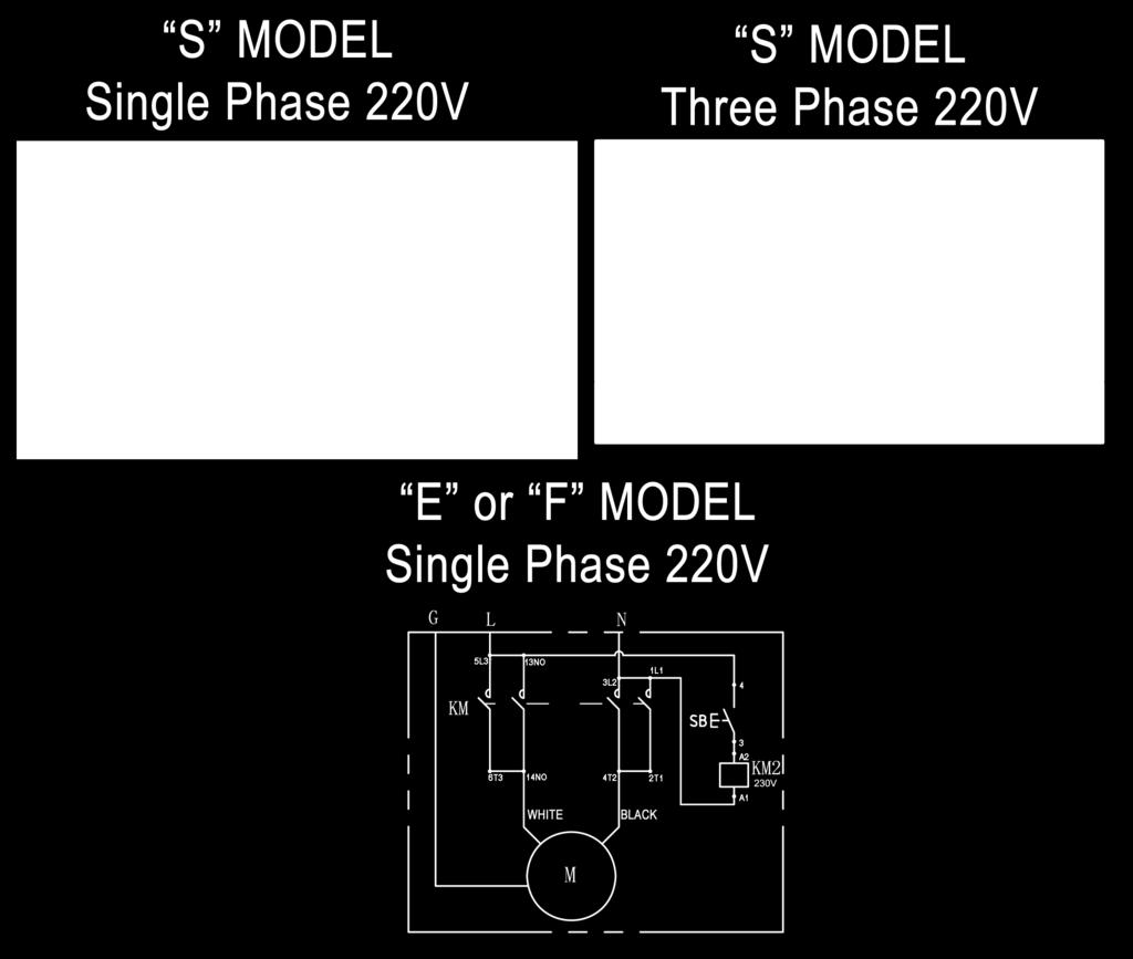
23 DNGER! DO NOT PERFORM NY MINTENNCE OR INSTLLTION OF NY COMPONENTS WITH OUT FIRST ENSURING THT ELECTRICL POWER HS BEEN DISCONNECTED T THE SOURCE OR PNEL ND CNNOT BE RE-ENERGIZED UNTIL LL MINTENNCE ND/OR INSTLLTION PROCEDURES RE COMPLETED. IMPORTNT POWER-UNIT INSTLLTION NOTES DO NOT run power uni wih no oil. Damage o pump can occur. The power uni mus be kep dry. Damage o power uni caused by waer or oher liquids such as deergens, acid ec., is no covered under warrany. Improper elecrical hook-up can damage moor and will no be covered under warrany. Moor can no run on 0HZ wihou a physical change in moor. Use a separae breaker for each power uni. Proec each circui wih ime delay fuse or circui breaker. For vol, single phase, use a 2 amp fuse. For vol, hree phase, use a 20 amp fuse. For vol, hree phase, use a 1 amp fuse. Insallaion and adjusmen. DO NOT aemp o raise vehicle unil a horough operaion check has been compleed. ll wiring mus be performed by a cerified elecrician only. Idenify which Power Uni he lif was shipped wih by looking on he daa ag affixed o he Power Uni moor head. if he model number begins wih he leer S hen use he S wiring diagrams. If he model number begins wih he leer E or F hen use he E or F wiring diagrams. SEE WIRING INSTRUCTIONS FFIXED TO MOTOR FOR PROPER WIRING INSTRUCTIONS. 23
24 24

25 STEP 11 (Power Uni Hook Up) 1. Have a CERTIFIED ELECTRICIN run he power supply o moor. Refer o he daa plae found on he moor for proper power supply and wire size. RISK OF EXPLOSION! This equipmen has inernal arcing or PRTS THT MY SPRK and should no be exposed o flammable vapors. Moor should no be locaed in a recessed area or below floor level. NEVER expose moor o rain or oher damp environmens. DMGE TO MOTOR CUSED BY WTER IS NOT COVERED UNDER WRRNTY. I IMPORTNT NOTE: CUTION Never operae he moor on line volage less han 208V. Moor damage may occur which is no covered under warrany. Have a cerified elecrician run appropriae power supply o moor. Size wire for 2 amp circui. See Moor Operaing Daa Table. IMPORTNT: Use separae circui for each power uni. Proec each circui wih ime delay fuse or circui breaker. For single phase V, use 2 amp fuse. Three phase V, use 2 amp fuse. For hree phase 400V and above, use 1 amp fuse. ll wiring mus comply wih NEC and all local elecrical codes. Fig STEP 12 (Insalling The Slack Safey Springs) The following seps involve he SLCK CBLE SFETY DEVICE and MIN SFETY. Failure o follow hese seps could resul in serious injury or deah in he even of cable failure. 1. Insall he unaached end of he LL SFETY LOCK SPRINGS as shown. Make sure he spring ends are secure a boh ends. DO NOT TTEMPT TO RISE THE LIFT UNTIL THE SLCK SFETY SPRINGS RE TTCHED ND THE ROLLERS RE PULLED CLER FROM THE LDDER. (See Fig. 12.1) 2. Repea his sep for each corner of he lif. STEP 13 (Lif Sar Up / Final djusmens) Fig 12.1 Make sure he ends of all hree (3) springs are securely aached o he Safey Locks and Cross Cube anchor poins. 1. Make sure he POWER UNIT RESERVOIR is full wih 20-quars of 10-WT hydraulic oil or Dexron auomaic ransmission fluid. 2. Spray he inside of he Columns where he Slide Blocks glide wih a ligh lubrican or WD Tes he Power Uni by pressing he push-buon swich. If he moor sounds like i is operaing properly, raise he lif and check all hose connecions for leaks. If he moor ges ho or sounds peculiar, sop and check all elecrical connecions. 4. Before proceeding, double-check o make sure all Cables are properly posiioned wihin he grooves of LL sheaves. Make sure all cable sheave reaining pins and/ or clips are secure. Typical Power Uni shown, conrols and labels may vary. 2

 above he Top Lock Posiion.")
26 . Check o make sure ha all Slack Safey locks are cleared and free. (See Fig. 13.1) KEEP HNDS ND FEET CLER. Remove hands and fee from any moving pars. Keep fee clear of lif when lowering. void pinch poins. 9. Check all MIN SFETY LOCKS o make sure hey move freely and spring back o he lock posiion when released. Lubricae all SFETY PIVOT poins wih WD-40 or equal. Fig Coninue pressing he raise buon unil he Cables ge augh and he lif sars o move. 7. Raise lif unil he lif sops and lower unil he Safeies engage he Top Locking Posiion. djus each ladder so ha each Safey Lock ress on he corresponding Top Lock Posiion. Then adjus each Cable Nu so ha each Safey Lock is ONE INCH (1 ) above he Top Lock Posiion. The Cable Nus MUST be ighened unil here is a leas one inch of hreads proruding hrough he nu. (See Fig. 13.2) Failure o do so could resul in serious injury or deah. 10. Run he lif up and down a few imes o insure ha he locks are engaging uniformly and ha he safey release mechanisms are funcioning. Re-adjus if necessary. STEP 14 (nchoring The Columns) IMPORTNT NOTE: BendPak lifs are supplied wih insallaion insrucions and concree faseners meeing he crieria as prescribed by he merican Naional Sandard uomoive Lifs - Safey Requiremens for Consrucion, Tesing, and Validaion NSI/ LI LCTV Lif buyers are responsible for any special regional srucural and/ or seismic anchoring requiremens specified by any oher agencies and/ or codes such as he Uniform Building Code (UBC) and/ or Inernaional Building Code (IBC). 1. Before proceeding, DOUBLE CHECK MESURE- MENTS and make cerain ha he bases of each column are square and aligned wih he chalk line. Raise he lif up and down and make sure i operaes properly a he locaions prescribed by he markings on he floor. (See Fig. 14.1) Fig Fig ll cable nus MUST be ighened on each end unil here is a leas one inch of hreads proruding hrough he nu. Failure o do so could resul in serious injury or deah. NOTE: There will be iniial sreching of he cables in he beginning and/ or wih increased loads. djus he cables as oulined above a week afer firs use, hen every hree o six monhs hereafer depending on usage and/ or o compensae for srech. 2. Using he BSE PLTE on each column as a guide, drill each anchor hole approximaely deep using a roary hammer drill and 3/ 4 concree bi. (See Fig. 14.2) Fig fer connecing he air supply, press he PUSH BUTTON IR VLVE and check ha all Safey Locks are funcioning properly. Lower he lif by pressing he push buon air valve and Power Uni lowering valve simulaneously. 26
 1. Insall he approach ramps on he enry side of he lif. (See Fig. 1.1 &1.2) Fig. 1.1 4.")
")
 STEP 16 (Leveling / Synchronizing) 6.")

 Fig. 1.3 1.")
27 3. fer drilling, REMOVE DUST horoughly from each hole using compressed air and/ or brisle brush. Make cerain ha he Columns remain aligned wih he chalk line. LWYS WER SFETY GOGGLES. STEP 1 (Final ssembly) 1. Insall he approach ramps on he enry side of he lif. (See Fig. 1.1 &1.2) Fig ssemble he washers and nus on he anchors hen ap ino each hole wih a sledge unil he washer ress agains he base plae. Be sure ha if shimming is required, enough THREDS RE LEFT EXPOSED. (See Fig. 14.3) Fig If shimming is required, inser he shims as necessary under he base plae so ha when he anchor bols are ighened, he columns will be plumb. (See Fig. 14.4) Fig Fig Insall he fron ire sops a he forward end of he lif using he hex bols, nus and washers. (See Fig. 1.3) STEP 16 (Leveling / Synchronizing) 6. fer any necessary shims are insalled, ighen each anchor nu 3- urns pas hand igh. IMPORTNT - If anchor bols do no hold when orqued o require d amoun, concree mus be replaced. Saw cu and remove 24 x 24 square area under each column base hen re-pour wih reinforced 200 PSI concree o a deph of six inches minimum, keying new concree under exising floor. (See Fig. 14.) Fig Using an engineer s auomaic Level (ransi), locae he Level, a a convenien locaion in he shop ha allows an unobsruced view of all four corners of he runways. Fig Follow he Level manufacurer s insrucions for proper seup of he Level. Be sure i is DJUSTED LEVEL in all direcions. 3. Raise he lif approximaely Then lower lif unil all locking laches are engaged in each column and he runways are in full down posiion on locks. 4. Place a Level arge on he righ/ fron corner of he runway. (See Fig. 16.1)
 Noe: Use a pencil, marking pen or aach a paper clip ono he arge scale a he cross hair reference. 12. Raise he lif o full heigh. Lisen and wach as he locking laches click in place.")

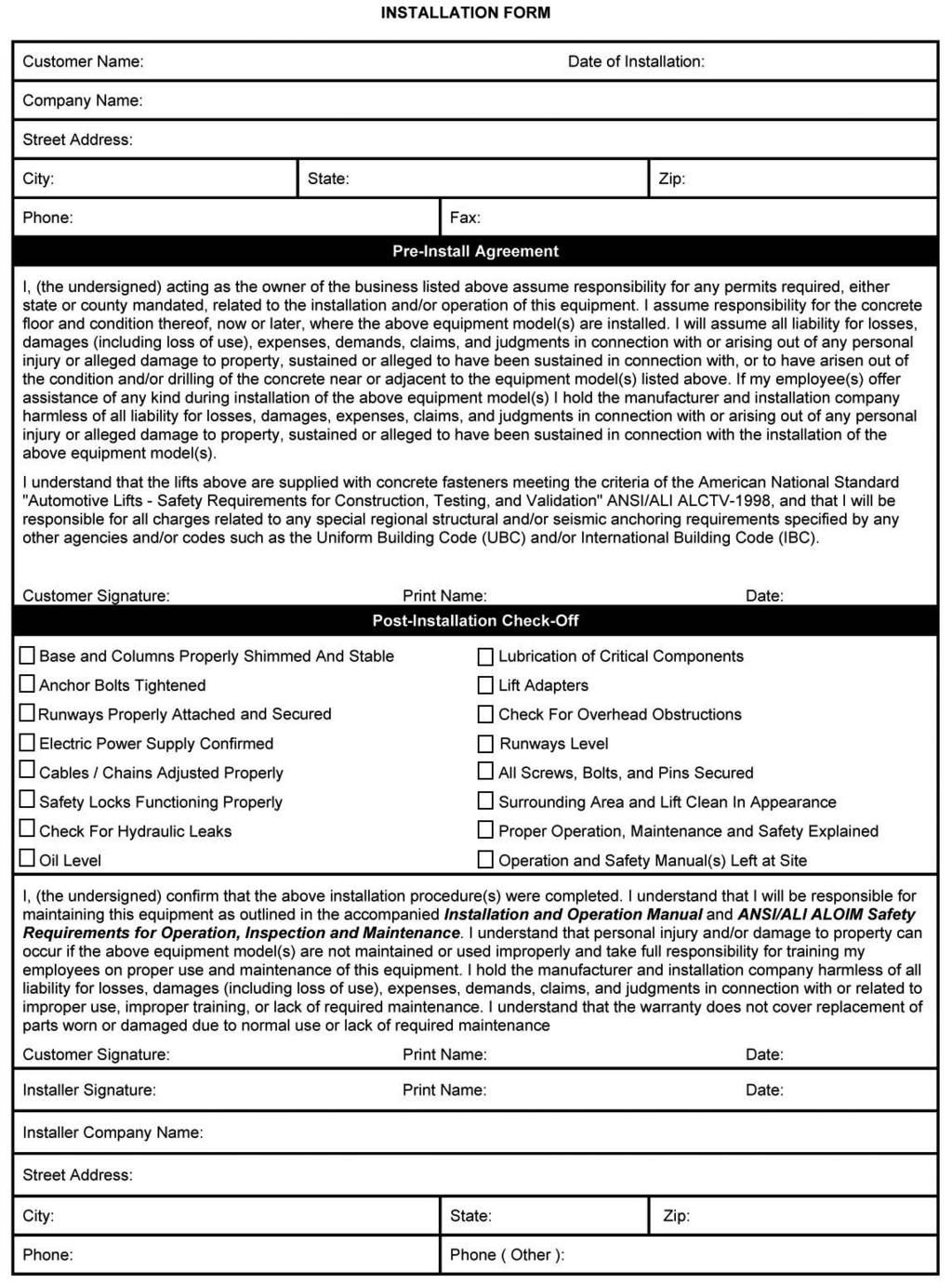
28 . Beginning wih posiion, sigh he level o he arge and mark he number or he graduaion on he inch scale of he arge ha aligns o he cross hairs of he Level, (See Fig. 16.1) Noe: Use a pencil, marking pen or aach a paper clip ono he arge scale a he cross hair reference. 12. Raise he lif o full heigh. Lisen and wach as he locking laches click in place. SYNCHRONIZE BY DJUSTING THE CBLES so ha all four laches click a he same ime. Make necessary adjusmens o he cables allowing COMPENSTION FOR STRETCH. Fig Safey locks may no click in a exacly he same ime when vehicles are being raised. They should be close. Be sure ha all four corners have passed he SME Safey Ladder Bar slo before lowering lif on he safey locks. NEVER lower lif on differen safey lock posiion or damage o he lif may resul. STEP 17 (Bleeding) 6. Nex, move he arge and place i a poin B on he runway. (See Fig. 16.1) 7. Roae he Level and focus on he arge scale. 8. djus he adjusmen nu on he safey ladder bar a he op of he Column a B unil he cross hair of he Level align o reference mark on he arge scale. (See Fig. 16.1) 9. Repea seps locaing he arge assembly a poins C and D and adjusing safey ladders a each corresponding Column unil he reference mark on he arge scale is on he cross hair of he Level. The runways are now level a all four poins. (See Fig. 16.1) 10. To complee he leveling procedures, SNUG ECH SFETY LDDER JM NUT agains he boom of he Column Top Plae. (See Fig. 16.2) Fig Nex, load vehicle such as an RV ono he lif. 1. Lif mus be fully lowered before changing or adding fluid. 2. Raise and lower lif six imes. The cylinder is selfbleeding. fer bleeding sysem, fluid level in power uni reservoir may be down. dd more fluid if necessary o raise lif o full heigh. I is only necessary o add fluid o allow full heigh raise. 3. To pressure es, run lif o full rise and run moor for approximaely 3-seconds afer lif sops. This will place pressure on he hydraulic sysem. Sop and check all fiings and hose connecions. Tighen or reseal if required. POST-INSTLLTION CHECK-OFF Columns properly shimmed and sable nchor Bols ighened Pivo / Sheave Pins properly aached Elecric power supply confirmed Cables adjused properly Safey Locks funcioning properly Check for hydraulic leaks Oil level Lubricaion of criical componens Check for overhead obsrucions ll Screws, Bols, and Pins securely fasened Surrounding area clean Operaion, Mainenance and Safey Manuals on sie. Perform an Operaional Tes wih a ypical vehicle 28
 per uni 174010 HD/ HDS-18; 27; 3 IR LINE KIT Par # Descripion Qy.")
29 OPTIONL EQUIPMENT INSTLLTION Rolling Jack maximum weigh capaciy for use wih HDS-18 or HDS-18X is 9,000 lb (4,082 kg) per uni HDS-27 or HDS-27X is 13,00 lb (6,124 kg) per uni HDS-3 or HDS-3X is 17,00 lb (7,938 kg) per uni HD/ HDS-18; 27; 3 IR LINE KIT Par # Descripion Qy / 4 Bulkhead Female Sraigh 3/ 8 Tube 003 3/ 8 Tube Male Elbow 90 1/ 4 NPT / 4 Male Run Tee 3/ 8 Tube #PST Ø3/ 8 x 10f Long Poly Tube Coil Hose Ø10mm Poly Flow Tube HD/ HDS-18X; 27X; 3X IR LINE KIT Par # Descripion Qy / 4 Bulkhead Female Sraigh 3/ 8 Tube 003 3/ 8 Tube Male Elbow 90 1/ 4 NPT / 4 Male Run Tee 3/ 8 Tube #PST Ø3/ 8 x 10f Long Poly Tube Coil Hose Ø10mm Poly Flow Tube 340 3

30 OPTIONL EQUIPMENT INSTLLTION 30

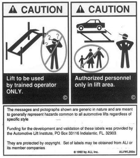
31 STEP 19 (Operaion Insrucions) OWNER/EMPLOYER RESPONSIBILITIES The Owner/Employer: Shall ensure ha lif operaors are qualified and ha hey are rained in he safe use and operaion of he lif using he manufacurer s operaing insrucions; LI/SM01-1, LI Lifing i Righ safey manual; LI/ST-90 LI Safey Tips card; NSI/LI LOIM-2000, merican Naional Sandard for uomoive Lifs-Safey Requiremens for Operaion, Inspecion and Mainenance; LI/WL Series, LI Uniform Warning Label Decals/Placards; and in he case of frame engaging lifs, LI/LP-GUIDE, Vehicle Lifing Poins/Quick Reference Guide for Frame Engaging Lifs. Shall display he lif manufacurer s operaing insrucions; LI/SM 93-1, LI Lifing I Righ safey manual; LI/ST-90 LI Safey Tips card; NSI/LI L- OIM-2000, merican Naional Sandard for uomoive Lifs-Safey Requiremens for Operaion, Inspecion and Mainenance; and in he case of frame engaging lifs, LI/ LP-GUIDE, Vehicle Lifing Poins/Quick Reference Guide for Frame Engaging Lifs; in a conspicuous locaion in he lif area convenien o he operaor. Shall provide necessary lockou/agou means for energy sources per NSI Z (R1993), Safey Requiremens for he Lockou/Tagou of Energy Sources, before beginning any lif repairs. Shall no modify he lif in any manner wihou he prior wrien consen of he manufacurer. Shall esablish procedures o periodically inspec he lif in accordance wih he lif manufacurer s insrucions or NSI/LI LOIM-2000, merican Naional Sandard for uomoive Lifs-Safey Requiremens for Operaion, Inspecion and Mainenance; and The Employer shall ensure ha lif inspecors are qualified and ha hey are adequaely rained in he inspecion of he lif. Shall esablish procedures o periodically mainain he lif in accordance wih he lif manufacurer s insrucions or NSI/LI LOIM-2000, merican Naional Sandard for uomoive Lifs-Safey Requiremens for Operaion, Inspecion and Mainenance; and The Employer shall ensure ha lif mainenance personnel are qualified and ha hey are adequaely rained in he mainenance of he lif. Shall mainain he periodic inspecion and mainenance records recommended by he manufacurer or NSI/LI LOIM-2000, merican Naional Sandard for uomoive Lifs-Safey Requiremens for Operaion, Inspecion and Mainenance. STEP 20 (Lif Operaion Safey) WRNING! TO VOID PERSONL INJURY ND/OR PROPERTY DMGE, PERMIT ONLY TRINED PERSONNEL TO OPERTE LIFT. FTER REVIEWING THESE INSTRUC- TIONS, PRCTICE USING LIFT CONTROLS BY RUNNING THE LIFT THROUGH FEW UNLODED CYCLES BEFORE LODING VEHICLE ON LIFT. NEVER RISE JUST ONE END, ONE CORNER, OR ONE SIDE OF VEHICLE. DILY inspec your lif. Never operae if i malfuncions or if i has broken or damaged pars. Use only qualified lif service personnel and genuine BendPak pars o make repairs. THOROUGHLY rain all employees in use and care of lif, using manufacurer s insrucions and Lifing I Righ and Safey Tips supplied wih he lif. NEVER allow unauhorized or unrained persons o posiion vehicle or operae lif. PROHIBIT unauhorized persons from being in shop area while lif is in use. DO NOT permi anyone on lif or inside vehicle when i is eiher being raised or lowered. 31
32 LIFT OPERTION SFETY (CONT D) LWYS keep area around lif free of ools, debris, grease and oil. NEVER overload lif. Capaciy of lif is shown on nameplae affixed o he lif. DO NOT sand in fron of he vehicle while i is being posiioned in lif bay. DO NOT block open or override self-closing lif conrols; hey are designed o reurn o he Off or Neural posiion when released. LWYS remain clear of lif when raising or lowering vehicles. LWYS use safey sands when removing or insalling heavy componens. DNGER! VISULLY CONFIRM THT LL PRIMRY SFETY LOCKS RE ENGGED BEFORE ENTERING WORK RE. SUSPENSION COMPONENTS USED ON THIS LIFT RE INTENDED TO RISE ND LOWER LIFT ONLY ND RE NOT MENT TO BE LOD HOLDING DEVICES. REMIN CLER OF ELEVTED LIFT UNLESS VISUL CONFIRMTION IS MDE THT LL PRIMRY SFETY LOCKS RE FULLY ENGGED ND THE LIFT IS LOWERED ONTO THE SFETY LOCKS, REFER TO INSTLLTION/ OPERTION MNUL FOR PROPER SFETY LOCK PROCEDURES ND/OR FURTHER INSTRUCTION. DO NOT go under raised vehicle if safey locks are no engaged. NEVER LEVE LIFT IN ELEVTED CONDITION unless all Safey Locks are engaged. VOID excessive rocking of vehicle while on lif. LWYS CLER RE if vehicle is in danger of falling. LWYS REMOVE ool rays, sands, ec. before lowering lif. LWYS RELESE safey locks before aemping o lower lif. DO NOT posiion yourself beween a wall and he lif. If he vehicle falls in ha direcion, you may be severely injured or killed. To Raise Lif; 1. Posiion vehicle ires in he cener of each Runway. 2. Se parking brake and use Wheel Chocks o hold vehicle in posiion. 3. Before raising vehicle, be sure all personnel are clear of he lif and surrounding area. Pay careful aenion o overhead clearances. 4. Raise he lif o he desired heigh by pressing he push buon on he power uni. NOTE: LLOW (2) SECONDS BETWEEN MOTOR STRTS. FILURE TO COMPLY MY CUSE MOTOR BURNOUT.. fer vehicle is raised o he desired heigh, lower he lif ono he neares Safey Lock. Do no allow Cables o become slack. LWYS ENSURE LL SFETY LOCKS RE ENGGED before enering work area. WRNING! WHEN LOWERING THE LIFT PY CREFUL TTEN- TION THT LL PERSONNEL ND OBJECTS RE KEPT CLER. LWYS KEEP VISUL LINE OF SIGHT ON THE LIFT T LL TIMES. LWYS MKE SURE THT LL LOCKS RE DISENGGED. IF ONE OF THE LOCKS INDVERTENTLY LOCKS UPON DESCENT THE VEHICLE MY DISMOUNT CUSING PERSONL INJURY OR DETH. To Lower Lif; 1. Before lowering vehicle, be sure all personnel are clear of he lif and surrounding area. Pay careful aenion o overhead clearances. Ensure all ools and equipmen have been cleared from under he lif. 2. Raise he lif off of he Safey Locks by pressing he push buon on he Power Uni. Make sure you raise he lif by a leas wo inches o allow adequae clearance for he locks o clear. 32
33 LIFT OPERTION SFETY (CONT D) 3. Press he push buon air safey valve and HOLD. 4. Push he LOWERING HNDLE on he Power Uni unil he lif has descended compleely. CUTION! IF YOU RE NOT COMPLETELY FMILIR WITH UTO- MOTIVE LIFT MINTENNCE PROCEDURES; STOP ND CONTCT THE MNUFCTURER FOR INSTRUC- TIONS. TO VOID PERSONL INJURY, PERMIT ONLY QULIFIED PERSONNEL TO PERFORM MINTE- NNCE ON THIS EQUIPMENT. Every 3 Monhs: Check anchor bol orque. nchors should be orqued o 90 f/lbs. Semi-nnually: Check fluid level of lif power uni and refill if required per lif insallaion insrucions. Replace all cauion, warning or safey relaed decals on he lif if unable o read or missing. Reorder labels from BendPak. Refer o NSI/LI LOIM bookle for periodic inspecion checklis and mainenance log shee. DILY MINTENNCE 1. Make a visual inspecion of LL MOVING PRTS and check for excessive signs of wear. 2. Check safey locks o ensure hey are in good operaing condiion. 3. Check cables and sheaves for wear. Replace worn pars as required wih genuine BendPak pars. 4. Inspec adapers for damage or excessive wear. Replace as required wih genuine BendPak pars. WEEKLY MINTENNCE 1. Lubricae all Sheave and rollers wih general purpose oil. 2. Check all Cable connecions, bols and pins o ensure proper mouning. 3. Lubricae Safey Lock pivo poins wih general purpose oil or WD-40. MONTHLY MINTENNCE 1. Check Safey Locks o ensure hey are in good operaing condiion. Lubricae locking lach shafs. Push release arm several imes for oil o penerae pivo poins. 2. Check equalizer cable ension. djus per lif insallaion insrucions. 3. Check all Cables for excessive signs of wear. 4. Make a visual inspecion of LL MOVING PRTS and check for excessive signs of wear. lways call local service represenaive if elecrical problems develop. lways replace LL FULTY PRTS before lif is pu back ino operaion. 33
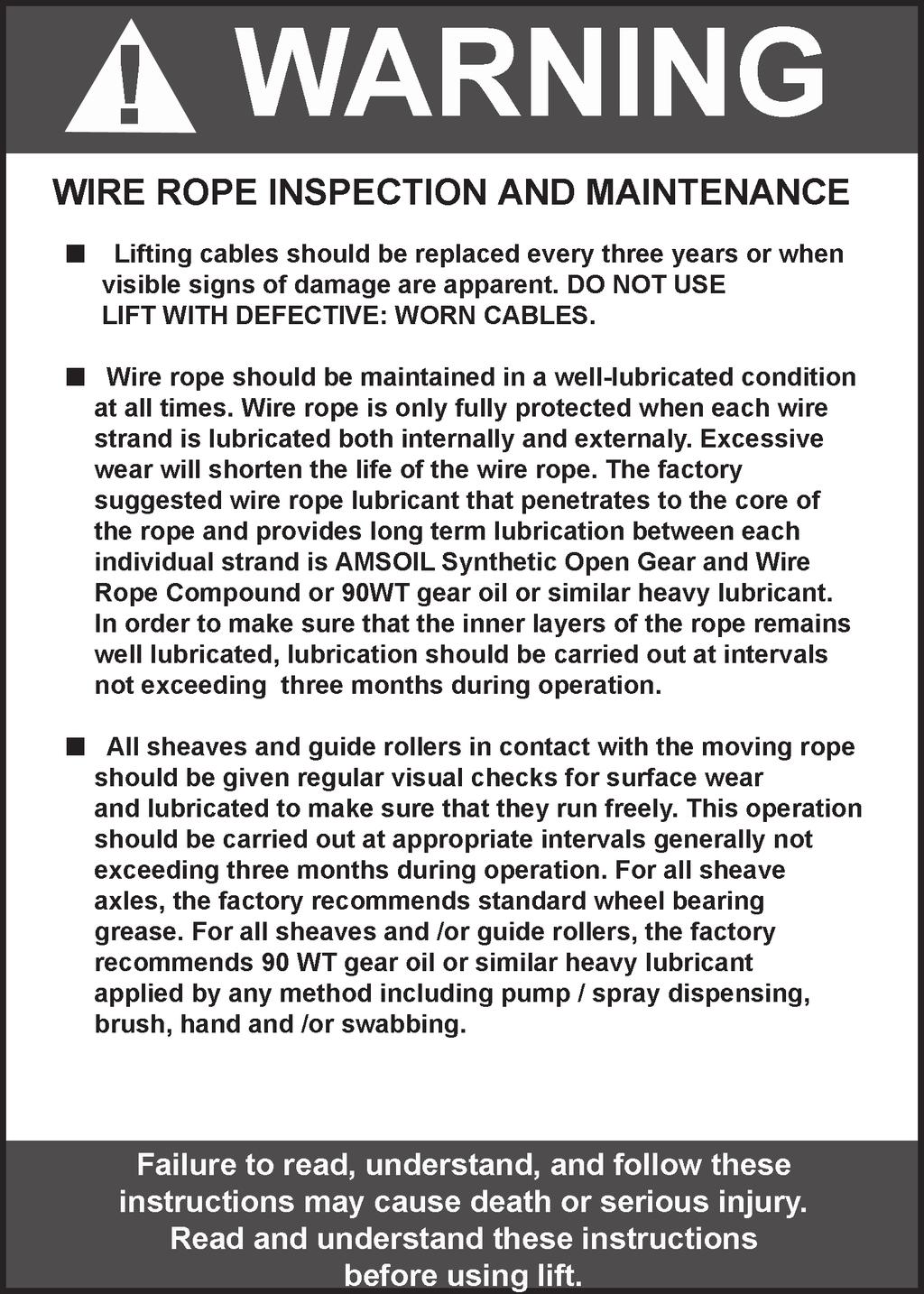
34 WIRE ROPE INSPECTION ND MINTENNCE Lifing cables should be replaced every hree - five years or when visible signs of damage are apparen. DO NOT USE LIFT WITH DEFECTIVE / WORN CBLES. Lifing cables should be mainained in a well-lubricaed condiion a all imes. Wire rope is only fully proeced when each wire srand is lubricaed boh inernal and exernal. Excessive wear will shoren he life of he wire rope. The facory suggesed wire rope lubrican ha peneraes o he core of he rope and provides long-erm lubricaion beween each individual srand is 90-WT gear oil or LMSOL Wire Rope Lubrican. In order o make sure ha he inner layers of he rope remain well lubricaed, lubricaion should be carried ou a inervals no exceeding hree monhs during operaion. ll sheaves and guide rollers in conac wih he moving rope should be given regular visual checks for surface wear and lubricaed o make sure ha hey run freely. This operaion should be carried ou a appropriae inervals generally no exceeding hree monhs during operaion. For all sheave axles, he facory recommends sandard wheel bearing grease. For all sheaves and/ or guide rollers, he facory recommends 90-WT gear oil or similar heavy lubrican applied by any mehod including pump / spray dispensing, brush, hand and/ or swabbing.. HOW OFTEN TO INSPECT Lifing cables should be visually inspeced a leas once each day when in use, as suggesed by merican Peroleum Insiue (PI) RP4 guidelines. ny lifing cables ha have me he crieria for removal mus be immediaely replaced. WHEN TO REPLCE LIFTING CBLES DUE TO BROKEN WIRES Lifing cables should be removed from service when you see six randomly disribued broken wires wihin any one lay lengh, or hree broken wires in one srand wihin one lay lengh. OTHER RESONS TO REPLCE LIFTING CBLES Corrosion ha pis he wires and/ or connecors. Evidence of kinking, crushing, cuing, bird-caging or a popped core. Wear ha exceeds 10% of a wire s original diameer. Evidence of hea damage. HOW TO FIND BROKEN WIRES The firs sep is o relax your rope o a saionary posiion and move he pick-up poins off he sheaves. Clean he surface of he rope wih a cloh a wire brush, if necessary so you can see any breaks. Flex he rope o expose any broken wires hidden in he valleys beween he srands. Visually check for any broken wires. One way o check for crown breaks is o run a cloh along he rope o check for possible snags. Wih an awl, probe beween wires and srands and lif any wires ha appear loose. Evidence of inernal broken wires may require a more exensive rope examinaion. 34


35 3
36 36
37 Safe Lif Operaion uomoive and ruck lifs are criical o he operaion and profiabiliy of your business. The safe use of his and oher lifs in your shop is criical in prevening employee injuries and damage o cusomer s vehicles. By operaing lifs safely you can insure ha your shop is profiable, producive and safe. Safe operaion of auomoive lifs requires ha only rained employees should be allowed o use he lif. TRINING SHOULD INCLUDE, BUT NOT LIMITED TO: Proper posiioning of he vehicle on he runway. (See manufacurers minimize wheel base loading requiremens.) Use of he operaing conrols. Undersanding he lif capaciy. Proper use of jack sands or oher load supporing devices. Proper use, undersanding and visual idenificaion of safey lock devices and heir operaion. Reviewing he safey rules. Proper housekeeping procedures (lif area should be free of grease, oil, ools, equipmen, rash, and oher debris) daily inspecion of he lif should be compleed prior o is use. Safey devices, operaing conrols, lif arms and oher criical pars should be inspeced prior o using he lif. ll mainenance and repairs of he lif should be compleed by following he manufacurer s requiremens. Lif repair pars should mee or exceed OEM specificaions. Repairs should only be compleed by a qualified lif echnician. The vehicle manufacurer s recommendaions should be used for spoing and lifing he vehicle. LIFT OPERTION SFETY I is imporan ha you know he load limi. Be careful ha you do no overload he lif. If you are unsure wha he load limi is, check he daa plae found on one of he lif columns or conac he manufacurer. The cener of graviy should be followed closely o wha he manufacurer recommends. lways make sure you have proper overhead clearance. ddiionally, check ha aachmens, ( vehicle signs, campers anennas, ec. ) are no in he way. Be sure ha prior o he vehicle being raised, he doors, runk, and hood are closed securely Prior o being raised, make sure here is no one sanding closer han six fee from he lif fer posiioning he vehicle on he lif runways, se he emergency brake, make sure he igniion is off, he doors are closed, overhead obsrucions are cleared, and he ransmission is in neural. Double check ha he auomaic chock devices are in posiion and hen when he lif is raised, observe he chocks Pu pads or adapors in he righ posiion under he conac poins ha have been recommended The lif should be raised jus unil he vehicle s wheels are abou one foo off he ground. If conac wih he vehicle is uneven or i appears ha he vehicle is no siing secure, carefully lower he lif and readjus. lways consider poenial problems ha migh cause a vehicle o slip, i.e., heavy cargo, undercoaing, ec. 37
38 Pay aenion when walking under a vehicle ha is up on he hydraulic lif DO NOT Leave he conrols while he lif is sill in moion. DO NOT sand direcly in fron of he vehicle or in he bay when vehicle is being loaded or driven ino posiion. DO NOT Go near vehicle or aemp o work on he vehicle when being raised or lowered. REMIN CLER of lif when raising or lowering vehicle. DO NOT rock he vehicle while on he lif or remove any heavy componen from vehicle ha may cause excessive weigh shif. DO NOT lower he vehicle unil people, maerials, and ools are clear LWYS INSURE ha he safeies are engaged before any aemp is made o work on or near vehicle. Some vehicle mainenance and repair aciviies may cause he vehicle o shif. Follow he manufacurer s guidelines when performing hese operaions. The use of jack sands or alernae lif poins may be required when compleing some repairs. RED ND UNDERSTND all safey warning procedures before operaing lif. KEEP HNDS ND FEET CLER. Remove hands and fee from any moving pars. Keep fee clear of lif when lowering. void pinch poins. ONLY TRINED OPERTORS should operae his lif. ll non-rained personnel should be kep away from work area. Never le non-rained personnel come in conac wih, or operae lif. USE LIFT CORRECTLY. Use lif in he proper manner. Never use lifing adapers oher han wha is approved by he manufacurer. DO NOT override self-closing lif conrols. CLER RE if vehicle is on danger of falling. STY LERT. Wach wha you are doing. Use common sense. Be aware. CHECK FOR DMGED PRTS. Check for alignmen of moving pars, breakage of pars or any condiion ha may affec is operaion. Do no use lif if any componen is broken or damaged. NEVER remove safey relaed componens from he lif. Do no use lif if safey relaed componens are damaged or missing. When he lif is being lowered, make sure everyone is sanding a leas six fee away. Be sure here are no jacks, ools, equipmen, lef under he lif before lowering. lways lower he vehicle down slowly and smoohly. 38
39 POSSIBLE CUSE 1. ir in oil, (1,2,8,13) 2. Cylinder binding, (9) 3. Cylinder leaks inernally, (9) 4. Moor run backward under pressure, (11). Lowering valve leaks, (3,4,6,10,11) 6. Moor runs backwards, (7,14,11) 7. Pump damaged, (10,11) 8. Pump won prime, (1,8,13,14,3,12,10,11) 9. Relief valve leaks, (10,11) 10. Volage o moor incorrec, (7,14,11) LIFT WILL NOT RISE REMEDY INSTRUCTION 1. Check for proper oil level The oil level should be up o he bleed screw in he reservoir wih he lif all he way down. 2. Bleed cylinders See Insallaion Manual 3. Flush- Release valve o ge rid of Hold release handle down and sar uni allowing i possible conaminaion. o run for 1 seconds. 4. Diry oil Replace oil wih clean Dexron TF. Tighen all faseners Tighen faseners o recommended orques. 6. Check for free movemen of release If handle does no move freely, replace bracke or handle assembly. 7. Check moor is wired correcly. Compare wiring of moor o elecrical diagram on drawing. 8. Oil seal damaged or cocked Replace oil seal around pump shaf. 9. See Insallaion Manual Consul Lif Manufacurer 10. Replace wih new par Replace wih new par 11. Reurn uni for repair Reurn uni for repair 12. Check pump-mouning bols Bols should be 1 o 18 f. lbs. 13. Inle screen clogged Clean inle screen or replace 14. Check wall oule volages and wiring Make sure uni and wall oule are wired properly. 39
40 MOTOR WILL NOT RUN POSSIBLE CUSE 1. Fuse blown, (,2,1,3,4) 2. Limi swich burned ou, (1,2,3,4) 3. Microswich burned ou, (1,2,3,4) 4. Moor burned ou, (1,2,3,4,6). Volage o moor incorrec, (2,1,8) REMEDY INSTRUCTION 1. Check for correc volage Compare supply volage wih volage on moor name ag. Check ha he wire is sized correcly. N.E.C. able requires WG 10 for 2 mps. 2. Check moor is wired correcly Compare wiring of moor o elecrical diagram on drawing. 3. Don use exension cords ccording o N.E.C. : The size of he conducors should be such ha he volage drop would no exceed 3% o he farhes oule for power Do no run moor a 11 VC damage o he moor will occur. 4. Replace wih new par Replace wih new par. Rese circui breaker/ fuse Rese circui breaker/ fuse 6. Reurn uni for repair Reurn uni for repair 7. See Insallaion Manual See Insallaion Manual 8. Check wall oule volage and wiring Make sure uni and wall oule is wired properly. Moor mus run a 208/ 230 VC. POSSIBLE CUSE 1. Cylinders binding, (1) 2. Release valve clogged, (,4,2,3) 3. Pressure fiing oo long, (6) LIFT LOWERS SLOWLY OR NOT T LL REMEDY INSTRUCTION 1. See Insallaion Manual Consul Lif Manufacurer 2. Replace wih new par Replace wih new par 3. Reurn for repair Reurn for repair 4. Check oil Use clean 10-WT hydraulic oil or Dexron auomaic ransmission fluid only. If TF is conaminaed, replace wih clean TF and clean enire sysem.. Clean release valve Wash release valve in solven and blow ou wih air. 6. Replace fiing wih shor hread lead Replace fiing wih shor hread lead 40
41 POSSIBLE CUSE 1. ir in oil, (1,2,3,4) 2. Cylinder binding, () 3. Cylinder leaks inernally, () 4. Lif overloaded, (6,). Lowering valve leaks, (7,8,1,,9) 6. Moor runs backwards, (10,12,9) 7. Pump damaged, (,9) 8. Pump won prime, (1,2,3,4,,11,9) 9. Relief valve leaks, (8,,9) 10. Volage o moor incorrec, (10,12,) WILL NOT RISE LODED LIFT REMEDY INSTRUCTION 1. Check oil level The oil level should be up o he bleed screw in he reservoir wih he lif all he way down.] 2. Check/ Tighen inle ubes Replace inle hose assembly. 3. Oil seal damaged or cocked Replace oil seal and insall 4. Bleed cylinders See Insallaion Manual. See Insallaion Manual Consul Lif Manufacurer 6. Check vehicle weigh Compare weigh of vehicle o weigh limi of he lif. 7. Flush release valve Hold release handle down and sar uni allowing i o run for 1 seconds. 8. Replace wih new par Replace wih new par 9. Reurn uni for repair Reurn uni for repair 10. Check moor is wired correcly Compare wiring of moor o elecrical diagram on uni drawing 11. Inle screen clogged Clean inle screen or replace. 12. Check wall oule volage and wiring Make sure uni and wall oule is wired properly. IMPORTNT If vehicle becomes sranded in he air, follow all operaion insrucions as shown on pages 31, 32, and 39. If afer observing ha all mechanical locks are released and he lif sill fails move following all sandard operaing procedures, immediaely sop using he lif and conac facory or facory approved service cener for furher insrucions. 41
42 LIFT WILL NOT STY UP POSSIBLE CUSE 1. ir in oil, (1,2,3) 2. Check valve leaks, (6) 3. Cylinders leak inernally, (7) 4. Lowering valve leaks, (4,,1,7,6). Leaking fiings, (8) REMEDY INSTRUCTION 1. Check oil level The oil level should be up o he bleed screw in he reservoir wih he lif all he way down. 2. Oil seal damaged and cocked Replace oil seal around pump shaf. 3. Bleed cylinder Refer o Insallaion Manual. 4. Flush release valve Hold release handle down and sar uni allowing i o run for 1 seconds.. Replace wih new valve Replace wih new valve. 6. Reurn uni for repair Reurn uni for repair. 7. See Insallaion Manual Consul Lif Manufacurer. 8. Check complee hydraulic sysem for leaks tighen all hydraulics fiings and inspecs all hoses. 42
 SE 0-1-2 SE Grade SE Grade 8 SOCKET HED CP SCREW CLSS 4.8 CLSS 8.8 CLSS 10.9 CLSS 12.9 1/4-20 M6 x 1.")

43 Grease Por / Lubricaion Locaions Lubricae Once Week Torque Recommendaions VLUES RE STTED IN FOOT POUNDS (f-lb) Bol Size (SE) Bol Size (Meric) SE SE Grade SE Grade 8 SOCKET HED CP SCREW CLSS 4.8 CLSS 8.8 CLSS 10.9 CLSS /4-20 M6 x /16-18 M8 x /8-16 M10 x / /2-13 M12 x /16-12 M14 x /8-11 M16 x /4-10 M18 x /8-9 M22 x /4 nchor Bols 7 MIN 110 MX 43
44 44
45 MINTENNCE RECORDS 4
46 REVISION REV DESCRIPTIO N DT E E DITED B Y ECO # PRODUCTION RELESE, DERIVED FROM /02/201 3 TM DETIL SCLE 1 : 4 ITEM NO DO NOT PRT NUMBER SCLE DIMENSIONS DRWING RE IN MM N ME DT E DESCRIPTION QT Y RE V HDS-18 SERIES LRGE WINDOW CROSSTUBE SSEMBL Y 1 HDS-18 POWER SIDE RMP SSEMBL Y 1 N HDS-18 DRIVE UP RMP SSEMBL Y HDS-18 SERIES SMLL WINDOW CROSSTUBE SSEMBL Y 1 HDS-18 OFF SIDE RMP WELDMEN T 1 C HDS-18 SERIES SFETY LDDER WELDMEN T HD/HDS-18/27/3 SERIES POST WELDMEN T 3 HD/HDS-18/27/3 SERIES POWER POST WELDMEN T 1 NUT M22 x 2. N L NUT M22 x 2. WSHER M22 x 0mm FL T D RWN TM 0/02/ LEMONWOOD DR. SNT PUL, C CHECKED N OTE: UNLESS OTHERWISE SPECIFIED SEE SHIPPING INSTRUCTIONS FOR FINL FSTEN NUTS ND WSHERS TO SFETY ORDER SHOWN FOR SHIPMENT PCKGING LDDERS IN NEXT SSEMBLY MTERIL: SIZE: THIRD NGLE PROJECTION TITLE: SIZE DWG. HDS-18 LIFT SUPERSTRUCTURE PROPRIETRY ND CONFIDENTIL INFORMTION CONTINED IN THIS DRWING THE IS T HE SOLE PROPERTY OF BENDPK INC. NY WHOLE WITHOUT REPRODUCTION IN PRT OR S S CLE: 1: 0 SHEET 1 OF 1 P T HE WRITTEN PERMISSION OF BENDPK INC. IS ROHIBITED. NO REV 46
47 1 DETIL SCLE 1 13 : B NOTE: SEE SHIPPING INSTRUCTIONS FOR FINL PCKGING INSERT PRTS BG INTO PRTS BOX FOR SHIPMENT THRED 3104 WITH 441 ONTO CBLES FOR SHIPMENT HOSES ND CBLES IN REPRESENTTIONL FORM DETIL SCLE 1 : B 12 DO NOT SCLE DRWING DIMENSIONS RE IN MM N ME DT E D RWN TM 0/07/ LEMONWOOD DR. SNT PUL, C CHECKED THIRD NGLE PROJECTION TITLE: PRTS BOX HDS-18 MTERIL: SIZE: SIZE DWG. PROPRIETRY ND CONFIDENTIL INFORMTION CONTINED IN THIS DRWING THE IS T HE SOLE PROPERTY OF BENDPK INC. NY WHOLE WITHOUT REPRODUCTION IN PRT OR S S CLE: 1:2 SHEET 1 OF 1 P T HE WRITTEN PERMISSION OF BENDPK INC. IS ROHIBITED. NO REV (*) LENGTH FOR REFERENCE ONLY 7. UNLESS OTHERWISE SPECIFIED LL LBELS TO BE PPLIED TO POSTS RECEIVED LIFT FOR PLCEMENT TO BE DDED BY REQUEST FTER PINTING. SEE ONLY REVISION REV DESCRIPTIO N DT E E DITED B Y ECO # PRODUCTION RELESE, DERIVED FROM /07/201 3 TM ITEM PRT NUMBER DESCRIPTIO N QT Y RE V NO HDS-18/27/3 SERIES PRTS B G 1 B HDS-18 SERIES CBLE SSY Ø16 x 4143mm S T 1 C HDS-18 SERIES CBLE SSY Ø16 x 10840mm S T 1 D HDS-18 SERIES CBLE SSY Ø16 x 9093mm S T 1 C 980 HDS-18 SERIES CBLE SSY Ø16 x 886mm S T 1 D PUSH BUTTON IR SSEMBL Y 1 D HD-SERIES FLEX TUBE BRCKET PLT E 1 F HD-SERIES FLEX TUBE NGL E 1 E FLEX TUBE SSEMBLY 1320m m 1 B NYLOCK NUT M30 x POWER UNIT VIBRTION DMPENE R 1 B HDS-18/27/3 TIRE STOP WELDMEN T HDS-18 SERIES TOP PLTE WELDMEN T HDS-18/18 HYD. HOSE SSY Ø10 x 3770m m /4" POLY-FLO TUBIN G 24000mm * HD/HDS-18/27 SERIES HINGE PI N WSHER M30 x 6 FL T HDS SERIES FOOT PLT E B 3/4" x 3/4 " HDS TRUCK SERIES INSTLLTION MNU L SFETY MNUL LI / SM BENDPK #90 WRRNTY CR D LIGN OIM OPERTION INSPECTION & MINTENNCE SFETY TIPS CRD LI-ST POST SERIL T G PRODUCT DT LBE L MX CP DNGER 18 K WRNING LI/WL LI SFETY INSTRUCTIONS STICKE R MNUFCTURER LBE L POST DECL KIT, LESS L I 1 NEXT SSEMBLY
48 8 REVISION REV DESCRIPTIO N DT E E DITED B Y ECO # PRODUCTION RELESE, DERIVED FROM /02/201 3 TM DETIL SCLE 1 3 : 4 6 ITEM NO DO NOT PRT NUMBER SCLE DIMENSIONS DRWING RE IN MM N ME DT E DESCRIPTION QT Y RE V HDS-27 POWER SIDE RMP SSEMBL Y 1 M HDS-27 OFF SIDE RMP WELDMEN T 1 C HDS-27 SERIES SMLL WINDOW CROSSTUBE SSEMBL Y HDS-27 DRIVE UP RMP SSEMBL Y 2 B HDS-27 SERIES LRGE WINDOW CROSSTUBE SSEMBL Y 1 HD/HDS-18/27/3 SERIES POST WELDMEN T 3 HD/HDS-18/27/3 SERIES POWER POST WELDMEN T HDS-27 SERIES SFETY LDDER WELDMEN T NUT M27 x 3.0 N L NUT M27 x WSHER M27 x 0m m D RWN TM 0/02/ LEMONWOOD DR. SNT PUL, C CHECKED N OTE: UNLESS OTHERWISE SPECIFIED SEE SHIPPING INSTRUCTIONS FOR FINL FSTEN NUTS ND WSHERS TO SFETY ORDER SHOWN FOR SHIPMENT PCKGING LDDERS IN NEXT SSEMBLY MTERIL: SIZE: THIRD NGLE PROJECTION TITLE: SIZE DWG. HDS-27 LIFT SUPERSTRUCTURE PROPRIETRY ND CONFIDENTIL INFORMTION CONTINED IN THIS DRWING THE IS T HE SOLE PROPERTY OF BENDPK INC. NY WHOLE WITHOUT REPRODUCTION IN PRT OR S S CLE: 1: 0 SHEET 1 OF 1 P T HE WRITTEN PERMISSION OF BENDPK INC. IS ROHIBITED. NO REV 48
49 1 DETIL SCLE 1 : NOTE: UNLESS OTHERWISE SPECIFIED SEE SHIPPING INSTRUCTIONS FOR FINL PCKGING INSERT PRTS BG INTO PRTS BOX FOR SHIPMENT THRED 3104 WITH 441 ONTO CBLES FOR SHIPMENT HOSES ND CBLES IN REPRESENTTIONL FORM (*) LENGTH FOR REFERENCE ONLY LL LBELS TO BE PPLIED TO POSTS FTER PINTING. SEE RECEIVED LIFT FOR PLCEMENT TO BE DDED BY REQUEST ONLY NEXT SSEMBLY REVISION REV DESCRIPTIO N DT E E DITED B Y ECO # PRODUCTION RELESE, DERIVED FROM /08/201 3 TM ITEM NO DO NOT PRT NUMBER SCLE DRWING DIMENSIONS RE IN MM N ME DT E D RWN TM 0/08/ LEMONWOOD DR. SNT PUL, C CHECKED THIRD NGLE D ESCRIPTION QTY. RE V HDS-18/27/3 SERIES PRTS B G 1 B HD-SERIES FLEX TUBE BRCKET PLT E 1 F HD-SERIES FLEX TUBE NGL E 1 E FLEX TUBE SSEMBLY 1320m m 1 B NYLOCK NUT M30 x POWER UNIT VIBRTION DMPENE R 1 B HDS-27 SERIES CBLE SSY Ø16 x 4127mm S T HDS-27/27 CBLE SSY Ø16 x 1221mm S T 1 D HDS-27/27 CBLE SSY Ø16 x 10483mm S T 1 C HDS-27 SERIES CBLE SSY Ø16 x 8mm S T 1 P USH BUTTON IR SSEMBL 1 D Y HDS-18/27/3 TIRE STOP WELDMEN T HDS-27 SERIES TOP PLTE WELDMEN T m /4" POLY-FLO TUBIN G 24000mm * HD/HDS-18/27 SERIES HINGE PI N WSHER M30 x 6 FL T HDS SERIES FOOT PLT E B 3/4" x 3/4 " HDS TRUCK SERIES INSTLLTION MNU L SFETY MNUL LI / SM BENDPK #90 WRRNTY CR D LIGN OIM OPERTION INSPECTION & MINTENNCE SFETY TIPS CRD LI-ST MNUFCTURER LBE L POST SERIL T G PRODUCT DT LBE L H DS-27/27 HYDRULIC HOSE SSY Ø10 x 38m 1 B MX CP DNGER 27 K WRNING LI/WL LI SFETY INSTRUCTIONS STICKE R POST DECL KIT, LESS L I 1 PROJECTION TITLE: PRTS BOX HDS-27 MTERIL: SIZE: SIZE DWG. PROPRIETRY ND CONFIDENTIL INFORMTION CONTINED IN THIS DRWING THE IS T HE SOLE PROPERTY OF BENDPK INC. NY WHOLE WITHOUT REPRODUCTION IN PRT OR S S CLE: 1:2 SHEET 1 OF 1 P T HE WRITTEN PERMISSION OF BENDPK INC. IS ROHIBITED. NO REV 49
50 NOTE: UNLESS OTHERWISE SPECIFIED. 1. SEE SHIPPING INSTRUCTIONS FOR FINL PCKGING 2. FSTEN NUTS ND WSHERS TO SFETY LDDERS IN ORDER SHOWN FOR SHIPMENT 2 NEXT SSEMBLY REVISION REV DESCRIPTION DTE EDITED BY ECO# PRODUCTION RELESE, DERIVED FROM /03/2013 TM DETIL SCLE 1 : 4 ITEM NO NUMBER PRT SIZE: DIMENSIONS RE IN MM DESCRIPTION QTY REV HDS-18 SERIES LRGE WINDOW CROSSTUBE SSEMBLY HDS-18X POWER SIDE RMP SSEMBLY 1 B HDS-18X OFF SIDE RMP WELDMENT HDS-18 DRIVE UP RMP SSEMBLY HDS-18 SERIES SMLL WINDOW CROSSTUBE SSEMBLY HDS-18 SERIES SFETY LDDER WELDMENT HD/HDS-18/27/3 SERIES POST WELDMENT HD/HDS-18/27/3 SERIES POWER POST WELDMENT NUT M22 x 2. NL NUT M22 x WSHER M22 x 0mm FLT DO NOT SCLE DRWING MTERIL: DRWN CHECKED NME DTE TM 0/03/2013 THIRD NGLE PROJECTION PROPRIETRY ND CONFIDENTIL THE INFORMTION CONTINED IN THIS DRWING IS THE SOLE PROPERTY OF BENDPK INC. NY REPRODUCTION IN PRT OR S WHOLE WITHOUT THE WRITTEN PERMISSION OF BENDPK INC. IS PROHIBITED. TITLE: SIZE DWG. NO LEMONWOOD DR. SNT PUL, C HDS-18X LIFT SUPERSTRUCTURE SCLE: 1:60 REV SHEET 1 OF 1 0
51 1 B 13 DETIL SCLE 1 : DETIL SCLE 1 : B DO NOT SCLE DRWING DIMENSIONS RE IN MM CHECKED N ME DT E D RWN TM 0/07/ LEMONWOOD DR. SNT PUL, C THIRD NGLE PROJECTION TITLE: PRTS BOX HDS-18X MTERIL: SIZE: SIZE DWG. NO PROPRIETRY ND CONFIDENTIL INFORMTION CONTINED IN THIS DRWING THE IS T HE SOLE PROPERTY OF BENDPK INC. NY WHOLE WITHOUT REPRODUCTION IN PRT OR S 1:2 P ROHIBITED. T HE WRITTEN PERMISSION OF BENDPK INC. IS REV 1 S CLE: SHEET 1 OF NOTE: SEE SHIPPING INSTRUCTIONS FOR FINL PCKGING UNLESS OTHERWISE SPECIFIED INSERT PRTS BG INTO PRTS BOX FOR SHIPMENT THRED 3104 WITH 441 ONTO CBLES FOR SHIPMENT HOSES ND CBLES IN REPRESENTTIONL FORM (*) LENGTH FOR REFERENCE ONLY LL LBELS TO BE PPLIED TO POSTS FTER PINTING. SEE RECEIVED LIFT FOR PLCEMENT ND TO BE DDED BY REQUEST ONLY REVISION REV DESCRIPTIO N DT E E DITED B Y ECO # PRODUCTION RELESE, DERIVED FROM /07/201 3 TM ITEM NO PRT NUMBER D ESCRIPTION QT Y RE V 1 0 HDS-18/27/3 SERIES PRTS B G 1 B 2 94 HDS-18X/X CBLE SSEMBLY Ø16 x 7089mm S T HDS-18X/X CBLE SSEMBLY Ø16 x 8832mm S T HDS-18X/X CBLE SSEMBLY Ø16 x 1498mm S T HDS-18X/X CBLE SSEMBLY Ø16 x 16732mm S T PUSH BUTTON IR SSEMBL Y 1 D HD-SERIES FLEX TUBE BRCKET PLT E 1 F HD-SERIES FLEX TUBE NGL E 1 E FLEX TUBE SSEMBLY 1320m m 1 B NYLOCK NUT M30 x POWER UNIT VIBRTION DMPENE R 1 B HDS-18/27/3 TIRE STOP WELDMEN T HDS-18 SERIES TOP PLTE WELDMEN T 4 HYD. HOSE SSY Ø10 x 6782m m 1 1 /4" POLY-FLO TUBIN G 24000mm * HD/HDS-18/27 SERIES HINGE PI N WSHER M30 x 6 FL T HEVY DUTY 4 POST FOOT PLT E B 3/4" x 3/4" WEJI T HDS TRUCK SERIES INSTLLTION MNU L SFETY MNUL LI / SM BENDPK #90 WRRNTY CR D LIGN OIM OPERTION INSPECTION & MINTENNCE SFETY TIPS CRD LI-ST POST SERIL T G PRODUCT DT LBE L MX CP DNGER 18 K WRNING LI/WL LI SFETY INSTRUCTIONS STICKE R MNUFCTURER LBE L POST DECL KIT, LESS L I DIP STICK SSEMBLY (CE ) 1 NEXT SSEMBLY
52 REVISION REV DESCRIPTIO N DT E E DITED B Y ECO # PRODUCTION RELESE, DERIVED FROM /02/201 3 TM DETIL SCLE 1 : 4 ITEM NO DO NOT PRT NUMBER SCLE DIMENSIONS DRWING RE IN MM N ME DT E DESCRIPTION QT Y RE V HDS-27 SERIES LRGE WINDOW CROSSTUBE SSEMBL Y HDS-27 SERIES SMLL WINDOW CROSSTUBE SSEMBL Y HDS-27 DRIVE UP RMP SSEMBL Y 2 B HDS-27X POWER SIDE RMP SSEMBL Y 1 L HDS-27X OFF SIDE RMP WELDMEN T 1 C HD/HDS-18/27/3 SERIES POWER POST WELDMEN T HD/HDS-18/27/3 SERIES POST WELDMEN T HDS-27 SERIES SFETY LDDER WELDMEN T NUT M27 x 3.0 N L WSHER M27 x 0m m NUT M27 x D RWN TM 0/02/ LEMONWOOD DR. SNT PUL, C CHECKED N OTE: UNLESS OTHERWISE SPECIFIED SEE SHIPPING INSTRUCTIONS FOR FINL FSTEN NUTS ND WSHERS TO SFETY ORDER SHOWN FOR SHIPMENT PCKGING LDDERS IN NEXT SSEMBLY MTERIL: SIZE: THIRD NGLE PROJECTION TITLE: SIZE DWG. HDS-27X LIFT SUPERSTRUCTURE PROPRIETRY ND CONFIDENTIL INFORMTION CONTINED IN THIS DRWING THE IS T HE SOLE PROPERTY OF BENDPK INC. NY WHOLE WITHOUT REPRODUCTION IN PRT OR S S CLE: 1:6 0 SHEET 1 OF 1 P T HE WRITTEN PERMISSION OF BENDPK INC. IS ROHIBITED. NO REV 2
53 1 4 DETIL SCLE 1 : NOTE: SEE SHIPPING INSTRUCTIONS FOR FINL PCKGING INSERT PRTS BG INTO PRTS BOX FOR SHIPMENT THRED 3104 WITH 441 ONTO CBLES FOR SHIPMENT HOSES ND CBLES IN REPRESENTTIONL FORM ITEM NO PRT NUMBE R D ESCRIPTIO N QTY. RE V HDS-18/27/3 SERIES PRTS B G 1 B HDS-27 SERIES CBLE SSY Ø16 x 4127mm ST HDS-27 SERIES CBLE SSY Ø16 x 8mm ST HDS-27X/27X CBLE SSY Ø16 x 12007mm ST 1 D HDS-27X/27X CBLE SSY Ø16mm x 13739mm ST 1 D DO NOT SCLE DRWING DIMENSIONS RE IN MM N ME DT E D RWN TM 0/08/ LEMONWOOD DR. SNT PUL, C CHECKED THIRD NGLE PROJECTION TITLE: PRTS BOX HDS-27X MTERIL: SIZE: SIZE DWG. PROPRIETRY ND CONFIDENTIL INFORMTION CONTINED IN THIS DRWING THE IS T HE SOLE PROPERTY OF BENDPK INC. NY WHOLE WITHOUT REPRODUCTION IN PRT OR S S CLE: 1:2 SHEET 1 OF 1 P HE WRITTEN PERMISSION OF BENDPK INC. IS ROHIBITED. NO REV T P USH BUTTON IR SSEMBL 1 D (*) LENGTH FOR REFERENCE ONLY 7. UNLESS OTHERWISE SPECIFIED LL LBELS TO BE PPLIED TO POSTS RECEIVED LIFT FOR PLCEMENT TO BE DDED BY REQUEST FTER PINTING. SEE ONLY NEXT SSEMBLY REVISION REV DESCRIPTIO N DT E E DITED B Y ECO # PRODUCTION RELESE, DERIVED FROM /08/201 3 TM Y HD-SERIES FLEX TUBE BRCKET PLT E 1 F HD-SERIES FLEX TUBE NGL E 1 E HDS-27 SERIES TOP PLTE WELDMEN T 4 F LEX TUBE SSEMBLY 1320m 1 B m NYLOCK NUT M30 x POWER UNIT VIBRTION DMPENE R 1 B HDS-18/27/3 TIRE STOP WELDMEN T HYD. HOSE SSY Ø10 x 6782m m /4" POLY-FLO TUBIN G 24000mm * HD/HDS-18/27 SERIES HINGE PI N WSHER M30 x 6 FL T HDS SERIES FOOT PLT E B 3/4" x 3/4 " HDS TRUCK SERIES INSTLLTION MNU L SFETY MNUL LI / SM BENDPK #90 WRRNTY CR D LIGN OIM OPERTION INSPECTION & MINTENNCE SFETY TIPS CRD LI-ST MNUFCTURER LBE L POST SERIL T G PRODUCT DT LBE L MX CP DNGER 27 K WRNING LI/WL 20 0 LI SFETY INSTRUCTIONS STICKE R 4 POST DECL KIT, LESS L I
54 REVISION REV DESCRIPTIO N DT E E DITED B Y ECO # PRODUCTION RELESE, DERIVED FROM /02/201 3 TM DETIL SCLE 1 : ITEM NO DO NOT SCLE DIMENSIONS PRT NUMBER DRWING RE IN MM N ME DT E DESCRIPTION QT Y RE V HDS-3 SERIES LRGE WINDOW CROSSTUBE SSEMBL Y HDS-3 SERIES SMLL WINDOW CROSSTUBE SSEMBL Y HDS-3 POWER SIDE RMP SSEMBL Y 1 K HDS-3 SERIES DRIVE UP RMP SSEMBL Y 2 C HDS-3 OFF SIDE RMP WELDMEN T 1 D HD/HDS-18/27/3 SERIES POST WELDMEN T HD/HDS-18/27/3 SERIES POWER POST WELDMEN T HDS-3 SERIES SFETY LDDER WELDMEN T NYLOCK NUT M30 x NUT M30 x WSHER M30 x 6 FL T D RWN TM 0/02/ LEMONWOOD DR. SNT PUL, C CHECKED N OTE: UNLESS OTHERWISE SPECIFIED SEE SHIPPING INSTRUCTIONS FOR FINL FSTEN NUTS ND WSHERS TO SFETY ORDER SHOWN FOR SHIPMENT PCKGING LDDERS IN NEXT SSEMBLY MTERIL: SIZE: THIRD NGLE PROJECTION TITLE: SIZE DWG. HDS-3 LIFT SUPERSTRUCTURE PROPRIETRY ND CONFIDENTIL INFORMTION CONTINED IN THIS DRWING THE IS NY HE SOLE PROPERTY OF BENDPK INC. WHOLE WITHOUT REPRODUCTION IN PRT OR S S CLE: 1: 0 SHEET 1 OF 1 P T HE WRITTEN PERMISSION OF BENDPK INC. IS ROHIBITED. NO REV T 4
55 T 1 6 DETIL SCLE 7 1 : DO NOT SCLE DRWING TITLE: DIMENSIONS RE IN MM N ME DT E D RWN TM 0/08/ LEMONWOOD DR. SNT PUL, C CHECKED THIRD NGLE PROJECTION PRTS BOX HDS-3 MTERIL: SIZE: SIZE DWG. PROPRIETRY ND CONFIDENTIL INFORMTION CONTINED IN THIS DRWING THE IS T HE SOLE PROPERTY OF BENDPK INC. NY WHOLE WITHOUT REPRODUCTION IN PRT OR S S CLE: 1:2 SHEET 1 OF 1 P BENDPK INC. IS ROHIBITED. NO REV HE WRITTEN PERMISSION OF NOTE: UNLESS OTHERWISE SPECIFIED SEE SHIPPING INSTRUCTIONS FOR FINL PCKGING INSERT PRTS BG INTO PRTS BOX FOR SHIPMENT THRED 30 WITH 4032 ONTO CBLES FOR SHIPMENT HOSES ND CBLES IN REPRESENTTIONL FORM (*) LENGTH FOR REFERENCE ONLY LL LBELS TO BE PPLIED TO POSTS FTER PINTING. SEE RECEIVED LIFT FOR PLCEMENT TO BE DDED BY REQUEST ONLY NEXT SSEMBLY REVISION REV DESCRIPTIO N DT E E DITED B Y ECO # PRODUCTION RELESE, DERIVED FROM /08/201 3 TM ITEM NO PRT NUMBER D ESCRIPTION QTY. RE V 1 0 HDS-18/27/3 SERIES PRTS B G 1 B PUSH BUTTON IR SSEMBL Y 1 D HDS-18/27/3 TIRE STOP WELDMEN T HDS-3 SERIES CBLE SSY Ø19 x 4102mm S T 1 D HDS-3 SERIES CBLE SSY Ø19 x 836mm S T 1 D HDS-3/3 CBLE SSY Ø19 x 1042mm S T 1 D HDS-3/3 CBLE SSY Ø19 x 12167mm S T 1 D POWER UNIT VIBRTION DMPENE R 1 B HD-SERIES FLEX TUBE NGL E 1 E HD-SERIES FLEX TUBE BRCKET PLT E 1 F HDS-3 SERIES TOP PLTE WELDMEN T HD/HDS-3 SERIES HINGE PI N FLEX TUBE SSEMBLY 1320m m 1 B NYLOCK NUT M36 x HDS-3/3 HYD. HOSE SSY Ø10 x 38m m /4" POLY-FLO TUBIN G 24000mm * WSHER M36 x 66 FL T HDS SERIES FOOT PLT E B 3/4" x 3/4 " HDS TRUCK SERIES INSTLLTION MNU L SFETY MNUL LI / SM BENDPK #90 WRRNTY CR D LIGN OIM OPERTION INSPECTION & MINTENNCE SFETY TIPS CRD LI-ST MNUFCTURER LBE L POST SERIL T G PRODUCT DT LBE L MX CP DNGER 3 K WRNING LI/WL 20 0 LI SFETY INSTRUCTIONS STICKE R 4 POST DECL KIT, LESS L I
56 REVISION REV DESCRIPTIO N DT E E DITED B Y ECO # PRODUCTION RELESE, DERIVED FROM /02/201 3 TM DETIL 8 SCLE 1 : 4 ITEM NO DO NOT PRT NUMBER SCLE DIMENSIONS DRWING RE IN MM N ME DT E DESCRIPTION QT Y RE V HDS-3 SERIES LRGE WINDOW CROSSTUBE SSEMBL Y 1 HDS-3 SERIES DRIVE UP RMP SSEMBL Y 2 C HDS-3X OFF SIDE RMP WELDMEN T 1 D HDS-3X POWER SIDE RMP SSEMBL Y 1 K HD/HDS-18/27/3 SERIES POWER POST WELDMEN T 1 HD/HDS-18/27/3 SERIES POST WELDMEN T HDS-3 SERIES SFETY LDDER WELDMEN T HDS-3 SERIES SMLL WINDOW CROSSTUBE SSEMBL Y 1 NYLOCK NUT M30 x 3. NUT M30 x 3. WSHER M30 x 6 FL T D RWN TM 0/02/ LEMONWOOD DR. SNT PUL, C CHECKED N OTE: UNLESS OTHERWISE SPECIFIED SEE SHIPPING INSTRUCTIONS FOR FINL FSTEN NUTS ND WSHERS TO SFETY ORDER SHOWN FOR SHIPMENT PCKGING LDDERS IN NEXT SSEMBLY MTERIL: SIZE: THIRD NGLE PROJECTION TITLE: SIZE DWG. HDS-3X LIFT SUPERSTRUCTURE PROPRIETRY ND CONFIDENTIL INFORMTION CONTINED IN THIS DRWING THE IS T HE SOLE PROPERTY OF BENDPK INC. NY WHOLE WITHOUT REPRODUCTION IN PRT OR S S CLE: 1:6 0 SHEET 1 OF 1 P HE WRITTEN PERMISSION OF BENDPK INC. IS ROHIBITED. NO REV T 6
57 1 6 DETIL SCLE 1 : NOTE: UNLESS OTHERWISE SPECIFIED SEE SHIPPING INSTRUCTIONS FOR FINL PCKGING INSERT PRTS BG INTO PRTS BOX FOR SHIPMENT THRED 30 WITH 4032 ONTO CBLES FOR SHIPMENT HOSES ND CBLES IN REPRESENTTIONL FORM (*) LENGTH FOR REFERENCE ONLY LL LBELS TO BE PPLIED TO POSTS FTER PINTING. SEE RECEIVED LIFT FOR PLCEMENT TO BE DDED BY REQUEST ONLY NEXT SSEMBLY REVISION REV DESCRIPTIO N DT E E DITED B Y ECO # PRODUCTION RELESE, DERIVED FROM /08/201 3 TM ITEM NO DO NOT PRT NUMBER SCLE DRWING DIMENSIONS RE IN MM N ME DT E D RWN TM 0/08/ LEMONWOOD DR. SNT PUL, C CHECKED THIRD NGLE D ESCRIPTION QTY. RE V HDS-18/27/3 SERIES PRTS B G 1 B PUSH BUTTON IR SSEMBL Y 1 D HDS-18/27/3 TIRE STOP WELDMEN T HDS-3 SERIES CBLE SSY Ø19 x 4102mm S T 1 D HDS-3X/X CBLE SSY Ø19 x 13691mm S T 1 D HDS-3X/X CBLE SSY Ø19 x 11976mm S T 1 D HDS-3 SERIES CBLE SSY Ø19 x 836mm S T 1 D POWER UNIT VIBRTION DMPENE R 1 B HD-SERIES FLEX TUBE NGL E 1 E HD-SERIES FLEX TUBE BRCKET PLT E 1 F HDS-3 SERIES TOP PLTE WELDMEN T 4 HD/HDS-3 SERIES HINGE PI N FLEX TUBE SSEMBLY 1320m m 1 B NYLOCK NUT M36 x HYD. HOSE SSY Ø10 x 6782m m /4" POLY-FLO TUBIN G 24000mm * WSHER M36 x 66 FL T HDS SERIES FOOT PLT E 4 B 3/4" x 3/4 " 16 - HDS TRUCK SERIES INSTLLTION MNU L SFETY MNUL LI / SM 93-1 BENDPK #90 WRRNTY CR D LIGN OIM OPERTION INSPECTION & MINTENNCE SFETY TIPS CRD LI-ST MNUFCTURER LBE L 4 POST SERIL T G PRODUCT DT LBE L MX CP DNGER 3 K WRNING LI/WL LI SFETY INSTRUCTIONS STICKE R 4 POST DECL KIT, LESS L I PROJECTION TITLE: PRTS BOX HDS-3X MTERIL: SIZE: SIZE DWG. PROPRIETRY ND CONFIDENTIL INFORMTION CONTINED IN THIS DRWING THE IS T HE SOLE PROPERTY OF BENDPK INC. NY WHOLE WITHOUT REPRODUCTION IN PRT OR S S CLE: 1:2 SHEET 1 OF 1 P T HE WRITTEN PERMISSION OF BENDPK INC. IS ROHIBITED. NO REV 7
58 2 REVISION REV DESCRIPTIO N DT E E DITED B Y ECO # PRODUCTION RELES E 0/06/200 9 C B DDED (20) 43 C UPDTED NEXT SSEMBLY B 2 B-00 B-003 UPDTED NEXT UPDTED NEXT SSEMBLY SSEMBLIES 12/22/ /2/ /30/2012 0/20/2013 TM TM T DETIL 22 SCLE 1 1 E : DETIL SCLE B 1 : DETIL SCLE 1 : NOTE: 17 SEE 10 UNLESS 9 DETIL SCLE 1 OTHERWISE D SHIPPING INSTRUCTIONS : 10 SPECIFIED FOR FINL DETIL SCLE F 1 : DIMENSIONS RE IN MM MTERIL: DRWING DETIL SCLE. SIZE: PROPRIETRY ND CONFIDENTIL INFORMTION CONTINED IN THIS DRWING THE IS PCKGING NEXT SSEMBLY ITEM NO PRT NUMBE R DESCRIPTIO N QT Y RE V FTG ELB -06 JIC -06 NP T FTG ELB 1/4 TUBE INS 3/8 NP T 2 - DO NOT ROTOR CLIP 18mm S S SCLE NUT M8 x 1.2 N L HHB M20 x 2. x 8 0 HHB M18 x 2. x 10m m HHB M8 x 1.2 x 2 FTG ELB -06 JIC -06L OR B WSHER M18 FL T WSHER M18 x 28 S L WSHER M8 x24 FL T NUT M20 x 2. N L HEX NUT M18 x 2. Nu, M4 X SHCS M4 x 0.7mm x 12m m 2 - WSHER, Ø4.3 x Ø9mm x 0.8m m 2 - FTG TEE 1/4-1/4-1/4 TUBE IN S 3 - WSHER M10 x Ø20 FL T HHB M10 x 1. x NUT M10 x 1. N L 8 - WSHER, M20 FL T CWSHER SHIM FOR LIFT S N ME DT E TITLE: SIZE T HE SOLE PROPERTY OF BENDPK INC. NY WHOLE WITHOUT REPRODUCTION IN PRT OR S S CLE: 1: 0 SHEET 1 OF 1 P T HE WRITTEN PERMISSION OF BENDPK INC. IS ROHIBITED. C 1 : D RWN C 0/06/ LEMONWOOD DR. SNT PUL, C CHECKED THIRD NGLE PROJECTION DWG. HDS-18/27/3 SERIES PRTS BG NO REV B 8
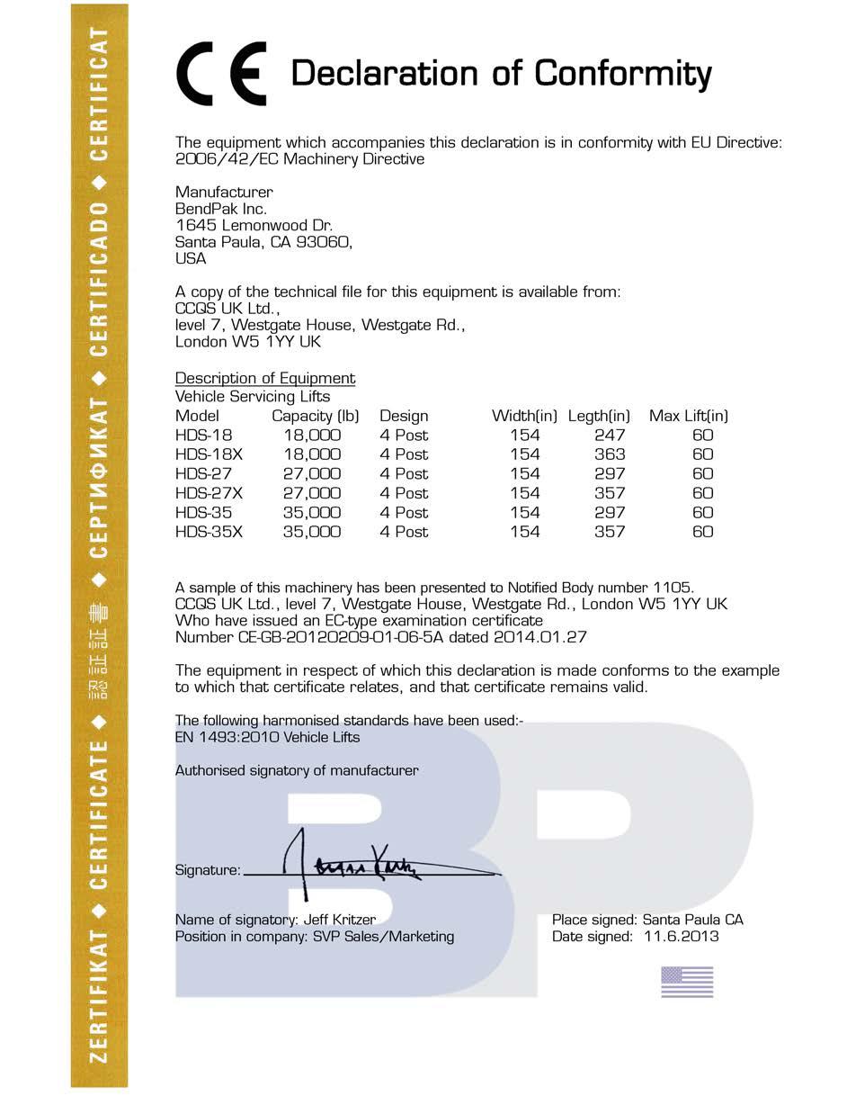
59 9

60 For Pars Or Service Conac: BendPak Inc. / Ranger Producs 164 Lemonwood Dr. Sana Paula, C Tel: Toll Free: Fax: pn#
INSTALLATION AND OPERATION MANUAL
 EUROPEAN USERS 400V 50Hz SUPPLY DETAILS ARE INCLUDED WITH ELECTRICAL CONTROL BOX. DISREGARD SUPPLY WIRING DETAILS IN THIS MANUAL INSTALLATION AND OPERATION MANUAL HEAVY-DUTY FOUR-POST ALIGNMENT LIFTS Models:
INSTALLATION AND OPERATION MANUAL
 EUROPEAN USERS 400V 50Hz SUPPLY DETAILS ARE INCLUDED WITH ELECTRICAL CONTROL BOX. DISREGARD SUPPLY WIRING DETAILS IN THIS MANUAL IMPORTANT SAFETY INSTRUCTIONS SAVE THESE INSTRUCTIONS PLEASE READ THE ENTIRE
INSTALLATION AND OPERATION MANUAL
 IMPORTANT SAFETY INSTRUCTIONS SAVE THESE INSTRUCTIONS PLEASE READ THE ENTIRE CONTENTS OF THIS MANUAL PRIOR TO INSTALLATION AND OPERATION. BY PROCEEDING WITH LIFT INSTALLATION AND OPERATION YOU AGREE THAT
INSTALLATION AND OPERATION MANUAL
 IMPORTANT SAFETY INSTRUCTIONS PLEASE READ THE ENTIRE CONTENTS OF THIS MANUAL PRIOR TO INSTALLATION AND OPERATION. BY PROCEEDING WITH LIFT INSTALLATION AND OPERATION YOU AGREE THAT YOU FULLY UNDERSTAND
INSTALLATION AND OPERATION MANUAL
 EUROPEAN USERS 400V 50Hz SUPPLY DETAILS ARE INCLUDED WITH ELECTRICAL CON- TROL BOX. DISREGARD SUPPLY WIR- ING DETAILS IN THIS MANUAL 14,000 POUND CAPACITY COMMERCIAL GRADE FOUR-POST LIFTS IMPORTANT SAFETY
INSTALLATION AND OPERATION MANUAL
 1,000 POUND CAPACITY MOTORCYCLE / ATV LIFT IMPORTANT SAFETY INSTRUCTIONS SAVE THESE INSTRUCTIONS PLEASE READ THE ENTIRE CONTENTS OF THIS MANUAL PRIOR TO INSTALLATION AND OPERATION. BY PROCEEDING WITH LIFT
INSTALLATION AND OPERATION MANUAL
 INSTALLATION AND OPERATION MANUAL PARKING LIFT / 7,000 POUND CAPACITY PLEASE READ THE ENTIRE CONTENTS OF THIS MANUAL PRIOR TO INSTALLATION AND OPERATION. BY PROCEEDING YOU AGREE THAT YOU FULLY UNDERSTAND
INSTALLATION AND OPERATION MANUAL
 Please read THE enire CONTENTS OF THIS MANUAL prior o insallaion AND OPERATION. BY PROCEEDING YOU AGREE THAT YOU FULLY UNDERSTAND AND COMPREHEND THE FULL CONTENTS OF THIS MANUAL. Forward his manual o all
INSTALLATION AND OPERATION MANUAL
 EUROPEN USERS 400V 50Hz SUPPLY DETILS RE INCLUDED WITH ELECTRICL CONTROL BOX. DISREGRD SUPPLY WIRING DETILS IN THIS MNUL IMPORTNT SFETY INSTRUCTIONS SVE THESE INSTRUCTIONS PLESE RED THE ENTIRE CONTENTS
INSTALLATION AND OPERATION MANUAL
 INSTALLATION AND OPERATION MANUAL 6,000 POUND CAPACITY PORTABLE MID RISE LIFT MODEL: MD-6XP PLEASE READ THE ENTIRE CONTENTS OF THIS MANUAL PRIOR TO INSTALLATION AND OPERATION. BY PROCEEDING YOU AGREE THAT
QUICKJACK WARNING INSTALLATION AND OPERATION MANUAL MODELS: BL-3500 BL ,500 / 5,000 POUND CAPACITY QUICKJACK
 ! IMPORTANT SAFETY INSTRUCTIONS SAVE THESE INSTRUCTIONS PLEASE READ THE ENTIRE CONTENTS OF THIS MANUAL PRIOR TO INSTALLATION AND OPERATION. BY PROCEEDING WITH JACK INSTALLATION AND OPERATION YOU AGREE
XSz 8... XSz 50 Solenoid actuated fail-safe safety valve
 > > /-way or size: G /4... G, /4... NT > > ouble valve conrol sysem, inherenly failsafe wihou residual pressure > > ynamic self monioring > > For use wih pneumaic cluch and brake sysems and oher -way safey
3 (R) 1 (P) N/en
 1 (P) N/en") 3/ way fail-safe safey valve, solenoid acuaed For mechanical presses and oher safey applicaions G /4... G, /4... NT Inherenly fail-safe wihou residual pressure ynamic self monioring ouble valve conrol
3/ way fail-safe safey valve, solenoid acuaed For mechanical presses and oher safey applicaions G /4... G, /4... NT Inherenly fail-safe wihou residual pressure ynamic self monioring ouble valve conrol
Instruction Manual. Rugged PCB type. 1 Terminal Block. 2 Function. 3 Series Operation and Parallel Operation. 4 Assembling and Installation Method
 Rugged PCB ype Insrucion Manual 1 Terminal Block Funcion.1...4.5.6.7 Inpu volage range Inrush curren limiing Overcurren proecion Overvolage proecion Oupu volage adjusmen range Isolaion Remoe ON/OFF E9
Dannmar EQUIPMENT SX-6/XL USER MANUAL. Dannmar Equipment 646 Flinn Avenue, Suite A Moorpark, CA Tel:
 Dannmar Equipmen 646 Flinn Avenue, Suie A Moorpark, CA 93021 Tel: 1-877-432-6627 www.dannmar.com Dannmar R EQUIPMENT SX-6/XL USER MANUAL PORTABLE MID-RISE SCISSOR LIFT 6,000 POUND CAPACITY Also known as
INSTALLATION AND OPERATION MANUAL
 EUROPEAN USERS 400V 0Hz SUPPLY DETAILS ARE IN- CLUDED WITH ELECTRICAL CONTROL BOX. DISREGARD SUPPLY WIRING DETAILS IN THIS MANUAL INSTALLATION AND OPERATION MANUAL 9,000 POUND CAPACITY COMMERCIAL GRADE
Automatic air-main charging and pressure control system for compressed air supplies
 Auomaic air-main charging and pressure conrol sysem for compressed air supplies Type PCS A module from he sysem -vacorol Swiching on-off a compressed air uni in a compressed air supply generally akes place
Flow Switch LABO-VHZ-S
 Flow Swich S Volumeric flow swiching Almos no effec from differing viscosiies Versaile, configurable swiching oupu in push-pull design Robus consrucion Compac design Characerisics he VHZ gearwheel flow
Type 14 Flanged Diaphragm
 izes: Body Maerials: Bonne Maerials: Diaphragms: pecificaions /" ", C, and,, G and EPDM and Also available in Nirile and FKM Type Flanged Diaphragm andard Feaures Flanged (ANI) face-o-face dimensions are
Filter Regulator with Back Flow Mechanism AW20K/30K/40K. How to Order. Symbol. Note 4) J N R W Z. Note 5) Note 6) Accessories Note 3) Symbol.
 J N R W Z. Note 5) Note 6) Accessories Note 3) Symbol.") Filer Regulaor wih ack Flow Mechanism K/3K/4K 3 K F 3 ow o Order ircui diagram 3 4K K hen he air supply is cu off and releasing he inle pressure o he amosphere, he residual pressure release of he oule
Filer Regulaor wih ack Flow Mechanism K/3K/4K 3 K F 3 ow o Order ircui diagram 3 4K K hen he air supply is cu off and releasing he inle pressure o he amosphere, he residual pressure release of he oule
Patent NO: 8,430,895. Revision (3) OPERATION INSTRUCTIONS. Fully Automatic AirGun by Air-Ordnance. HPA (High Pressure Compressed Air)
 OPERATION INSTRUCTIONS. Fully Automatic AirGun by Air-Ordnance. HPA (High Pressure Compressed Air)") Paen NO: 8,430,895 Fully Auomaic AirGun by Air-Ordnance Powered by: Co2 Nirogen HPA (High Pressure Compressed Air) OPERATION INSTRUCTIONS Revision (3) 6-2013 1. Please read his owner s manual compleely.
Paen NO: 8,430,895 Fully Auomaic AirGun by Air-Ordnance Powered by: Co2 Nirogen HPA (High Pressure Compressed Air) OPERATION INSTRUCTIONS Revision (3) 6-2013 1. Please read his owner s manual compleely.
Zelio Control Measurement Relays RM4L Liquid Level Relays
 Zelio Conrol Measuremen elays FNCTIONS These devices monior he levels of conducive liquids. They conrol he acuaion of pumps or valves o regulae levels; hey are also suiable for proecing submersible pumps
LSU RISK ASSESSMENT FORM Please read How to Complete a Risk Assessment before completion
 Please read How o Complee a Risk Assessmen before compleion EVENT OR ACTIVITY BEING RISK ASSESSED (add name of even where relevan) NAME OF DEPARTMENT Squad Training Neball DATE OF COMPLETION OF RISK ASSESSMENT
Using Rates of Change to Create a Graphical Model. LEARN ABOUT the Math. Create a speed versus time graph for Steve s walk to work.
 2.4 Using Raes of Change o Creae a Graphical Model YOU WILL NEED graphing calculaor or graphing sofware GOAL Represen verbal descripions of raes of change using graphs. LEARN ABOUT he Mah Today Seve walked
MCW100A, B Time Proportional Rotary Position Controller
 DESCRIPTION MCW100A, B Time Proporional Roary Posiion Conroller Issued: March 1992 The MCW100 Time Proporional Roary Posiion Conroller provides auomaic grade or seering conrol of paving, renching and curbing
CMA DiRECtions for ADMinistRAtion GRADE 6. California Modified Assessment. test Examiner and Proctor Responsibilities
 CMA 2012 California Modified Assessmen GRADE 6 DiRECions for ADMinisRAion es Examiner and Procor Responsibiliies Compleing all of he following seps will help ensure ha no esing irregulariies occur, ha
Type Control action Setpoint range Air Weight Volume flow % capacity I n /h kg. Pressure diff. 1) Pa
 Pa") 7.0/ RL 0 & 0: neumaic volume-flow conroller Used in conjuncion wih an orifice plae or a dnamic pressure sensor and a pneumaic damper drive for conrolling he air volume in air-condiioning ssems. For fixed,
7.0/ RL 0 & 0: neumaic volume-flow conroller Used in conjuncion wih an orifice plae or a dnamic pressure sensor and a pneumaic damper drive for conrolling he air volume in air-condiioning ssems. For fixed,
HafcoVac Compressed Air Industrial Vacuum Product Line
 HafcoVac Compressed Air Indusrial Vacuum Produc Line OPERATING INSTRUCTIONS & SAFETY MANUAL Thank you for your purchase of a HafcoVac produc. HafcoVac is a division of Hafco Foundry and Machine Company,
What the Puck? an exploration of Two-Dimensional collisions
 Wha he Puck? an exploraion of Two-Dimensional collisions 1) Have you ever played 8-Ball pool and los he game because you scrached while aemping o sink he 8-Ball in a corner pocke? Skech he sho below: Each
Owner s Manual SSCI. Wheeling, IL (800) Form No /08
 Form No /08") Owner s Manual Classic Bahing Table wih Access Door! Convenien Access Door & Roaing Ramp! Selec,, or Fauce Locaion! Pick 48-in or 60-in Table Widh! Choice of Inegral Splash Shields Model Numbers: 13022-LA-HJJRDR
Owner s Manual Classic Bahing Table wih Access Door! Convenien Access Door & Roaing Ramp! Selec,, or Fauce Locaion! Pick 48-in or 60-in Table Widh! Choice of Inegral Splash Shields Model Numbers: 13022-LA-HJJRDR
67.301/1. RLP 10: Pneumatic volume-flow controller. Sauter Components
 7.0/ RL 0: neumaic volume-flow conroller How energ efficienc is improved For demand-led conrol of he air volume in office rooms. Areas of applicaion Conrol of he suppl and exhaus air of individual rooms
Interpreting Sinusoidal Functions
 6.3 Inerpreing Sinusoidal Funcions GOAL Relae deails of sinusoidal phenomena o heir graphs. LEARN ABOUT he Mah Two sudens are riding heir bikes. A pebble is suck in he ire of each bike. The wo graphs show
Avoiding Component Failure in Industrial Refrigeration Systems
 Avoiding Componen Failure in Indusrial Refrigeraion Sysems By Tim Kroeger, segmen markeing manager indusrial refrigeraion, Asia Pacific & India The aricle caegorises and gives examples of ypical componen
SPECIAL WIRE ROPES The Value Line
 SPECIAL WIRE ROPES The Value Line INTRODUCTION Qualiy Producs, Ousanding Service and Comprehensive Technical Suppor I s wha oday s indusries expec from heir supplier parners. And ha s wha WireCo WorldGroup
KINEMATICS IN ONE DIMENSION
 chaper KINEMATICS IN ONE DIMENSION Secion 2.1 Displacemen Secion 2.2 Speed and Velociy 1. A paricle ravels along a curved pah beween wo poins P and Q as shown. The displacemen of he paricle does no depend
PRESSURE SENSOR TECHNICAL GUIDE INTRODUCTION FEATURES OF ELECTRIC PRESSURE SENSOR. Photoelectric. Sensor. Proximity Sensor. Inductive. Sensor.
 Proximiy INTRDUCTIN Pressur sensor The sensor convers of gases or liquid ino elecrical magniude wih he sensing elemen, and generaes he analog oupu proporional o applied level or he swiching oupu oggled
BGW-installation instruction for BGW-anchor with data head
 BGW-insallaion insrucion for BGW-anchor wih daa head BGW- lifing eye wih swivel for axial and diagonal lif. Grease he hread well. Lifing loop for diagonal lifing unil 45. Screw he loop unil he ground of
INSTALLATION AND USERS GUIDE
 INSALLAION AND USERS GUIDE BUDDY LIGH - WHIE & COLOR IMPORAN WARNING & SAFEY INSRUCIONS DANGER - SERIOUS BODILY INJURY OR DEAH CAN RESUL IF HESE LIGHS ARE NO INSALLED AND USED CORRECLY DANGER - INSALLERS,
Neighborhood & Community Services Department
 Bren Childers NCS Direcor Telephone: 270.393.3658 Fax: 270.901.3126 Bren.Childers@bgky.org 707 E. Main A PO Box 430 Bowling Green, Kenucky 42102 www.bgky.org January 20, 2017 Dear Propery Owner: Neighborhood
Installation & Technical Handbook for Marsh Industries Products
 Insallaion & echnical Handbook for Marsh Indusries Producs Page 4 Ensign Sewage Plan, Uni:Gem and Five Filer Insallaion 6 Ulra Polylok Insallaion 8 Sepic ank Insallaion 10 Marsh Ensign ank Dimensions 12
2020 ClearTrace In-line Turbidity System
 2020 ClearTrace In-line Turbidiy Sysem Code 5-0113-24V Code 5-0113-110V Preface This insrucion manual serves o explain he use of he LaMoe 2020 ClearTrace Inline Turbidiy Sysem and is wrien o cover as
Clemco Industries Corp. ISO 9001 Certified
 Clemco Indusries Corp. ISO 9001 Cerified 6 cuf Classic Blas Machines Exclusively from... SIMPLE, RUGGED, RELIABLE More han 75 years of reliable field service have made Clemco blas machines he preferred
MVS. Electronic fan speed controller for DIN rail. Key features. Article codes Technical specifications. Area of use
 MVS Elecronic fan speed conroller for DIN rail The MVS elecronic speed conrollers conrol he speed of single-phase volage conrollable elecric moors ( VAC / 5 6 z) according o a sandard inpu conrol signal.
Nozzle valve system for the variable atomization of very small liquid volumes
 Nozzle valve sysem for he variable aomizaion of very small liquid volumes VERY SMALL LIQUID VOLUMES MAXIMUM BENEFIT Innovaive spraying echnology opens up new applicaions The pressure o sandardize is increasing
Nozzle valve system for the variable atomization of very small liquid volumes
 Nozzle valve sysem for he variable aomizaion of very small liquid volumes V E R Y S M A L L L I Q U I D V O L U M E S M A X I M U M B E N E F I T Innovaive spraying echnology opens up new applicaions The
Reproduction. Not for. Mower - Roller Bar WARNING. Installation and Leveling Instructions. Attention Setup Personnel: Model: ,
 Mower - Roller Br Instlltion nd Leveling Instructions 4 Model: 9555, 9594 Attention Setup Personnel: 5 4 5 Model: 958, 9595 Model: 9559 Model: 959 The sfety wrnings provided in this guide nd in the trctor's
INSTRUCTIONS FOR USE. This file can only be used to produce a handout master:
 INSTRUCTIONS OR USE This file can only be used o produce a handou maser: Use Prin from he ile menu o make a prinou of he es. You may no modify he conens of his file. IMPORTNT NOTICE: You may prin his es
TRACK PROCEDURES 2016 RACE DAY
 TRACK PROCEDURES 2016 RACE DAY Pi gaes will officially open a 4:00pm for regular programs. Big shows will have earlier opening imes. Hauler parking may be available approximaely 1 hour prior o pi gaes
RECOMMENDATION FOR INTERCHANGEABLE STUD BOLTS AND TAP END STUDS FOR API SPEC 6A FLANGES
 Issue Dae: June 6 15 Revision B June 2010 RECOMMENDAION FOR INERCHANGEABE UD BO AND A END UD FOR AI EC 6A FANGE ECHNICA REOR R501 Revision B AWHEM publicaions may be use by anyone esiring o o so. Every
SBP200 SBP202 SBP202. See modifications table for upgrades, specifications and standards.
 SBP00 SBP00 Solid Back wih All Purpose Hardware BHD03L All Purpose, Adjusable Back Moun Bracke, Lef BHD03R All Purpose, Adjusable Back Moun Bracke, Righ adjusmen Up o 3 rear d adjusmen ar Up o 7 forw by
LEWA intellidrive. The mechatronic All-in-One pump system. intelligent flexible dynamic high precision. Foto: ratiopharm
 The mecharonic All-in-One pump sysem Foo: raiopharm inelligen flexible dynamic high precision For diverse applicaions: a limiless range of poenial uses Phoo: raiopharm Mixing wo media in one pump head:
Control elements. Fine adjustment. Function selector. Status indication. 24 V DC typ. 0,25 W / 0,25 VA. 24 V DC typ. 0,03 W / 0,09 VA. min.
 4 funcions 10 ime ranges Supply volage 24-240V AC/DC 1 change-over conac Widh 22,5 mm Conrol elemens Fine adjusmen Seing of ime range Funcion selecor Saus indicaion /: Supply volage : elay saus TECHNICAL
CAUTION - PUT SAFETY FIRST
 www.shoremaster.com DVS Vertical Lift (Double V Side): Frame ssembly Instructions. Models: 500DVS - 0ft Wide, 5000lb Capacity - Part #: 0079 600DVS - 0ft Wide, 6000lb Capacity - Part #: 0033.. 3.. 5. CUTION
Name Class Date. Step 2: Rearrange the acceleration equation to solve for final speed. a v final v initial v. final v initial v.
 Skills Workshee Mah Skills Acceleraion Afer you sudy each sample problem and soluion, work ou he pracice problems on a separae shee of paper. Wrie your answers in he spaces provided. In 1970, Don Big Daddy
Bill Turnblad, Community Development Director City of Stillwater Leif Garnass, PE, PTOE, Senior Associate Joe DeVore, Traffic Engineer
 Memorandum SRF No. 16 94 To: From: Bill Turnblad, Communiy Developmen Direcor Ciy of Sillwaer Leif Garnass, PE, PTOE, Senior Associae Joe DeVore, Traffic Engineer Dae: November 9, 16 Subjec: Downown Plan
POWER DANGER NOW COMMERCIAL. Controls Ba Erodes Slowly to Deliver Lo ACTIVE INGREDIENT: OTHER INGREDIENTS:...32% with Anti-Scale Additive
 748-275_Leslies Swimming Pool POWER Supplies Power Pro Tabs_20141014_26_748_.pdf P NOW wih Ani-Scale Addiive COMMERCIAL Conrols Ba Erodes Slowly o Deliver Lo KEEP OUT OF REACH OF CHILDREN DANGER Do no
Solid-state Timer H3BA-N. Broad Line-up of Series Solid-state Timer with Valuable Multiple-time Ranges and Multiple-operating Modes
 Solid-sae Timer H3BA-N Please read and undersand his caalog before purchasing he producs. Please consul your OMRON represenaive if you have any quesions or commens. Refer o Warrany and Applicaion Consideraions
Morningstar Investor Return
 Morningsar Invesor Reurn Morningsar Mehodology Paper March 3, 2009 2009 Morningsar, Inc. All righs reserved. The informaion in his documen is he propery of Morningsar, Inc. Reproducion or ranscripion by
Ministry of Agriculture and Rural Development Animal and Plant Health Regulatory Directorate
 Minisry of Agriculure and Rural Developmen Animal and Plan Healh Regulaory Direcorae Checklis for saus of slaugherhouses for cale, sheep and goas (General informaion) i Addis Ababa Ehiopia 1 1. Background
OWNER S MANUAL. Page: 1 of 8
 Air Needle Scaler OWNER S MANUAL WARNING: Read carefully and understand all INSTRUCTIONS before operating. Failure to follow the safety rules and other basic safety precautions may result in serious personal
SWIMMING POOL HEAT PUMP UNITS. Installation & Instruction Manual DURA - series
 SWIMMIG POO HEAT PUMP UITS Insallaion & Insrucion Manual DUA - series ev. 1.12 29.07.2014 Conens SWIMMIG POO HEAT PUMP UITS... 1! Conens... 2! 1. Preface... 3! 2. Specificaions... 4! 2.1 Technical daa
SUMMITTM 400 & 600. Natural Gas Barbecues. Step-By-Step Guide
 SUMMITTM 400 & 600 Natural Gas Barbecues Step-By-Step Guide W E B E R W E B E R W E B E R W E B E R Summit 400 NG Summit 600 NG CANADIAN GAS ASSOCIATION R A P P R O V E D WARNING: Follow all leak check
3/8" Dr. Air Butterfly Impact Wrench
 8192106 3/8" Dr. Air Butterfly Impact Wrench Owner s Manual Read and understand all instructions before use. Retain this manual for future reference. Specifications Construction: Polished aluminum and
DIMENSIONS AC Road travel
 DIMENSIONS AC 10009 Road ravel 04 DIMENSIONS AC 10009 Lifing operaion OUTRIGGER BASES TO CHOOSE FROM: A 13.54m x 13.538m B 12.0m x 12.0m (NEW) C 9.671m x 9.885m 05 HA /SSL (HA50) AC 10009 AC 10009 17 HA
INTENDED USE TECHNICAL SPECIFICATIONS
 1/2IN. HEAVY-DUTY AIR IMPACT WRENCH OWNER S MANUAL WARNING: Read carefully and understand all INSTRUCTIONS before operating. Failure to follow the safety rules and other basic safety precautions may result
AIR/OVER HYDRAULIC JACK 20 TON
 AIR/OVER HYDRAULIC JACK 0 TON 4487 ASSEMBLY AND OPERATING INSTRUCTIONS 349 Mission Oaks Blvd., Camarillo, CA 930 Visit our Web site at http://www.harborfreight.com Copyright 999 by Harbor Freight Tools.
AP Physics 1 Per. Unit 2 Homework. s av
 Name: Dae: AP Physics Per. Uni Homework. A car is driven km wes in hour and hen 7 km eas in hour. Eas is he posiive direcion. a) Wha is he average velociy and average speed of he car in km/hr? x km 3.3km/
! CAUTION! ! WARNING! General Information
 Great Plains Mfg., Inc. Installation Instructions Used with: 2SF24, 24-Foot Two-Section Drill General Information Two-Section, Hydraulic Folding Marker 2SF30, 30-Foot Two-Section Drill 2SBM30, 30-Foot
310 SERIES TILT-TO-LOAD ROTATOR. The Specialist In Drum Handling Equipment
 OPERATOR S MANUAL FOR MORSE TILT-TO-LOAD DRUM ROTATOR SAFETY INFORMATION: While Morse Manufacturing Co. drum handling equipment is engineered for safety and efficiency, a high degree of responsibility
Pool Ladder. Owner s Manual For: 48in (122 cm) model. For illustrative purposes only. Pool is not provided. IMPORTANT! DO NOT RETURN PRODUCT TO STORE
 model. For illustrative purposes only. Pool is not provided. IMPORTANT! DO NOT RETURN PRODUCT TO STORE") OWNER S MNUL Pool Ladder Owner s Manual For: 48in (122 cm) model For illustrative purposes only. Pool is not provided. IMPORTNT SFETY RULES Read, understand, and follow all instructions carefully before
OWNER S MNUL Pool Ladder Owner s Manual For: 48in (122 cm) model For illustrative purposes only. Pool is not provided. IMPORTNT SFETY RULES Read, understand, and follow all instructions carefully before
Monte Carlo simulation modelling of aircraft dispatch with known faults
 Loughborough Universiy Insiuional Reposiory Mone Carlo simulaion modelling of aircraf dispach wih known fauls This iem was submied o Loughborough Universiy's Insiuional Reposiory by he/an auhor. Ciaion:
Chapter : Linear Motion 1
 Te: Chaper 2.1-2.4 Think and Eplain: 1-3 Think and Sole: --- Chaper 2.1-2.4: Linear Moion 1 NAME: Vocabulary: disance, displacemen, ime, consan speed, consan elociy, aerage, insananeous, magniude, ecor,
KEY CONCEPTS AND PROCESS SKILLS. 1. An allele is one of the two or more forms of a gene present in a population. MATERIALS AND ADVANCE PREPARATION
 Gene Squares 61 40- o 2 3 50-minue sessions ACIVIY OVERVIEW P R O B L E M S O LV I N G SUMMARY Sudens use Punne squares o predic he approximae frequencies of rais among he offspring of specific crier crosses.
AC1810 / AC1810-A TECHNICAL SPECIFICATIONS. Operating Pressure psi ( kgs/cm²) [AC1810] Displacement. Net Weight
![AC1810 / AC1810-A TECHNICAL SPECIFICATIONS. Operating Pressure psi ( kgs/cm²) [AC1810] Displacement. Net Weight](/thumbs/83/88369739.jpg "AC1810 / AC1810-A TECHNICAL SPECIFICATIONS. Operating Pressure psi ( kgs/cm²) [AC1810] Displacement. Net Weight") Technical Specifications Operating Instructions Maintenance Information Troubleshooting Guide Parts Diagrams AC1810 / AC1810-A THE EVOLUTION OF PERFECTION CAUTION: Before attempting to use or service this
Technical Specifications Operating Instructions Maintenance Information Troubleshooting Guide Parts Diagrams AC1810 / AC1810-A THE EVOLUTION OF PERFECTION CAUTION: Before attempting to use or service this
35 TON HYDRAULIC PUNCH WARNING
 OPERATORS GUIDE REL-35T-PNC 35 TON HYDRAULIC PUNCH NOTICE Sizes, weights and tool specifications listed in this manual are subject to change without notice. Please consult factory for information and updates.
TEM# Air Hammer Combo USER'S MANUAL
 Air Tools TEM# 40 Air Hammer Combo USER'S MANUAL Read carefully and understand RULES FOR SAFE OPERATION and instructions before operating. Failure to follow the safety rules and other basic safety precautions
REL-46 WARNING NOTICE 15 TON SINGLE ACTING REMOTE HYDRAULIC CRIMPING HEAD. Compatible with RELIABLE R15 and P Style dies. REL-46 Manual
 OPERATORS ORS GUIDE REL-46 15 TON SINGLE ACTING REMOTE HYDRAULIC CRIMPING HEAD Compatible with RELIABLE R15 and P Style dies. RELIABLE EQUIPMENT & SERVICE CO., INC. 301 Ivyland Road Warminster, PA 18974
SPECIFICATIONS Type: Twin stack, single phase Tank: 4 gallon Air Output: PSI; PSI Max PSI: 125 PSI HP: 1.
 2 GALLON TWIN STACK AIR COMPRESSOR Model: 9526 DO NOT RETURN TO STORE. Please CALL 800-348-5004 for parts and service. CALIFORNIA PROPOSITION 65 WARNING: You can create dust when you cut, sand, drill or
3.00 m. 8. At La Ronde, the free-fall ride called the Orbit" causes a 60.0 kg person to accelerate at a rate of 9.81 m/s 2 down.
 Physics Prees: Torque 1. Newon s 2 nd Law 2. Kinemaics (Free fall, graphs, and combined wih F R = ma) Pracice Quesions/Problems 1. Wha is Newon s 2 nd Law? Name and explain i. 2. Prove ha acceleraion for
LUBRICATOR ASSEMBLY AND OPERATING INSTRUCTIONS
 AIR FILTER, REGULATOR AND LUBRICATOR 4035 ASSEMBLY AND OPERATING INSTRUCTIONS 349 Mission Oaks Blvd., Camarillo, CA 930 Visit our Web site at http://www.harborfreight.com Copyright 004 by Harbor Freight
INVERTER HEATPUMP FOR SWIMMING POOLS
 IVE HEATPUMP FO SWIMMIG POOS Insallaion & Insrucion Manual hea pumps 0-0071-1611 Table of conens 1. Preface 3. Specificaions.1 Performance Daa. Dimensions 6 3. Insallaion and Connecion 3.1 Hea Pump ocaion
Composite Pistol-Type Air Needle Scaler OWNER S MANUAL
 Composite Pistol-Type Air Needle Scaler OWNER S MANUAL WARNING: Read carefully and understand all INSTRUCTIONS before operating. Failure to follow the safety rules and other basic safety precautions may
1 DRIVE INDUSTRIAL IMPACT WRENCH
 1 DRIVE INDUSTRIAL IMPACT WRENCH 92622 ASSEMBLY AND OPERATING INSTRUCTIONS 3491 Mission Oaks Blvd., Camarillo, CA 93011 Visit our Web site at http://www.harborfreight.com Copyright 2004 by Harbor Freight
PDY TON HYDRAULIC CRIMPING TOOL WARNING
 OPERATORS ORS GUIDE PDY-1220 12 TON HYDRAULIC CRIMPING TOOL All information found in this guide must be read and understood before use or testing of this tool. Failure to read and understand these warnings
Cylinder Tilt Saddle Instruction Manual
 Cylinder Tilt Saddle Instruction Manual MODELS: SDT05, SDT10, SDT15, SDT25 SFA Companies 10939 N. Pomona Ave. Kansas City, MO 64153 Tel: 888-332-6419 - Fax: 816-448-2142 E-mail: sales@bvahydraulics.com
3/4 SafeClaw Anchorage Connectors
 Operations and Instruction Manual Model #4075 Portable Concrete Anchorage Connector ANSI Z359.1-07 5,000 lbs / 22kn OHSA 1910.66 & 1926.502 Effective: 01/2012 Expires: 01/2022 IM-0049 REVA 3/4 SafeClaw
ANALYSIS OF RELIABILITY, MAINTENANCE AND RISK BASED INSPECTION OF PRESSURE SAFETY VALVES
 ANALYSIS OF RELIABILITY, MAINTENANCE AND RISK BASED INSPECTION OF PRESSURE SAFETY VALVES Venilon Forunao Francisco Machado Mechanical Engineering Dep, Insiuo Superior Técnico, Av. Rovisco Pais, 049-00,
400C & 450C DUAL PERFORMANCE VALUE PACKS
 (Chrome) PART NO. 40013 (Silver) PART NO. 45012 (Chrome) PART NO. 45013 IMPORTANT: It is essential that you and any other operator of this product read and understand the contents of this manual before
Workfit -SR, Dual Monitor Short Surface
 User's Guide Workfit -SR, Dul Monitor Short Surfce Do not throw wy! Crdord locks needed for instlltion. Visit http://www.ergotron.com/workfi t-sr-instll for instlltion instructionl video. NOTE: 10 feet
REL-510H WARNING NOTICE 12 TON SINGLE ACTING REMOTE HYDRAULIC CRIMPING HEAD
 OPERATORS ORS GUIDE REL-510H 12 TON SINGLE ACTING REMOTE HYDRAULIC CRIMPING HEAD Compatible with U style and RELIABLE R12 shell type 12 ton compression dies. RELIABLE EQUIPMENT & SERVICE CO., INC. 92 Steamwhistle
100C Air Compressor Kit
 10010 100C Air Compressor (standard mounting bracket, CE Spec) 10014 100C Air Compressor (no leader hose or check valve, CE Spec) 10016 100C Air Compressor (with Omega Bracket, CE Spec) IMPORTANT: It is
INSTALLATION GUIDE Gas Rangetops
 INSTALLATION GUIDE Gas Rangetops Contents Wolf Gas Rangetops........................... 3 Safety Instructions............................ 4 Gas Rangetop Specifications.................... 5 Gas Rangetop
1/4 AIR RIVETER INSTRUCTION MANUAL
 ATD-5851 1/4 AIR RIVETER INSTRUCTION MANUAL Speci ca ons: Nosepiece: 1/8", 5/32", 3/16", 1/4" Rivet Capacity: 1/4 Motor: 1/2 Hp Air Inlet Thread NPT: 1/4 Air Hose I.D. Size: 3/8 (10mm) Avg. Air Consumption:
444C DUAL PERFORMANCE VALUE PACK
 (Chrome) PART NO. 44432 IMPORTANT: It is essential that you and any other operator of this product read and understand the contents of this manual before installing and using this product. SAVE THIS MANUAL
Installation, Operation & Maintenance Manual for Flo-Max Coupler Bracket Model FM150
 Installation, Operation & Maintenance Manual for Flo-Max Coupler Bracket Model FM150 January 2013 Form FVC 084 - Rev 02 IMPORTANT: KEEP THIS DOCUMENT WITH THE PRODUCT UNTIL IT REACHES THE END USER. 1.
Flexfence Swaging Unit. Product Manual. Release 02/16.
 Product Manual www.ingalcivil.com.au 1.0 Safety Precautions 1.1 Personal Protection While operating this equipment it is recommended that the following personal protective equipment be worn; Long sleeve
PROPORTIONING VALVE. Model 150 INSTRUCTION MANUAL. March 2017 IMS Company Stafford Road
 PROPORTIONING VALVE Model 150 INSTRUCTION MANUAL March 2017 IMS Company 10373 Stafford Road Telephone: (440) 543-1615 Fax: (440) 543-1069 Email: sales@imscompany.com 1 Introduction IMS Company reserves
A BETTER WAY THRU ROCKAWAY
 A BETTER WAY THRU ROCKAWAY Projec Underway is a communiy redevelopmen iniiaive focused on convering a negleced and underuilized roadway ha spans five linear miles along he Rockaway Peninsula ino a safer
IMPORTANT SAFETY INSTRUCTIONS
 IMPORTANT SAFETY INSTRUCTIONS CAUTION - To reduce risk of electrical shock: - Do not disassemble. Do not attempt repairs or modifications. Refer to qualified service agencies for all service and repairs.
"Pecos Bill Rides a Tornado" Stages Written by: Striker
 "Pecos Bill Rides a Tornado" Sages Wrien by: Sriker Now everyone in he Wes knows ha Pecos Bill could ride anyhing. No bronco could hrow hi, no sir! Fac is, I only heard of Bill geing' hrowed once in his