Section Instructor: Dr. Grant Kruger
|
|
|
- Sandra Smith
- 5 years ago
- Views:
Transcription
1 MABEL Robotic Foot Design Final Report ME 450 Fall 2010 Team 19 Matt Byrne Shane Larkin Allison Ryan Philip Vanderwall Section Instructor: Dr. Grant Kruger 1
2 TABLE OF CONTENTS 1. ABSTRACT EXECUTIVE SUMMARY INTRODUCTION ENGINEERING SPECIFICATIONS INFORMATION SOURCES CONCEPT GENERATION Functional Decomposition Brainstorming Five Main Concepts CONCEPT SELECTION PROCESS ENGINEERING DESIGN PARAMETER ANALYSIS Attachment Plate Stress Analysis Foot Plate Stress Analysis Lower Ankle Stress Analysis Upper Ankle Stress Analysis Rolling Motion Trigonometry Analysis Dynamics and Spring Analysis Material Selection Calculation Accuracy Material and Manufacturing Process Selection Design for Environmental Sustainability Design for Safety FINAL DESIGN Final Design Description Initial Fabrication Plan Assembly VALIDATION Withstands Applied Loads Moves Laterally Contact Sensor Weight Easy to Attach
3 10.6 Width, Height, and Length DISCUSSION RECOMMENDATIONS SUMMARY AND CONCLUSIONS ACKNOWLEDGEMENTS REFERENCES...43 APPENDIX A: QFD DIAGRAM APPENDIX B: ENGINEERING CHANGE NOTICES APPENDIX C: WRITING ASSIGNMENT APPENDIX D: DETAILED DRAWINGS APPENDIX E: BILL OF MATERIALS APPENDIX F: PARAMETER ANALYSIS CALCULATIONS APPENDIX G: VALIDATION TEST DATA APPENDIX H: MACHINING APPENDIX I: CONCEPT SKETCHES
4 1. ABSTRACT A planar bipedal robot, MABEL, is designed to test new control algorithms that optimize walking and running. MABEL s legs are currently terminated in point feet that contribute to instability when walking over uneven terrain or running. Feet would improve energy efficiency and the ability to walk over uneven terrain. Our task was to design, build, and test a set of feet for the robot. These feet must improve stability and efficiency, have sensors to detect the ground contact, and move freely normal to the direction of motion. 4
5 2. EXECUTIVE SUMMARY MABEL is a planar bipedal robot used to test control algorithms for achieving robust walking and stable running gaits. She is connected to a boom which allows her to walk in a circle with a large enough radius to approximate planar motion. MABEL s legs are terminated in point feet. This does not provide much traction and stability while walking over uneven terrain and running. Our task was to design, build and test a set of feet for the robot MABEL that will improve the energy efficiency of running and walking as well as her ability to walk over uneven ground. These feet must meet a number of customer requirements in order to be a viable design. The feet must be able to handle the loads from MABEL while she is walking, running or hopping. From previous data these loads peaked around 2000N; therefore it is a goal to design the feet to withstand loads of 4000N providing a safety factor of two. Since MABEL is constrained by a boom, simple trigonometry shows that as she moves up and down while walking, her distance from the center of the boom will fluctuate. Therefore, the feet must have a degree of freedom in the direction normal to motion allowing for a 3-4 cm shift. The feet must also be an acceptable size. Comparing dimensions from human and prosthetic feet, MABEL s feet will need to be 7-12cm wide, 18-31cm long and have a surface area contact of at least 50cm 2. The feet also need to be passive, which means that they can have no spring-like properties and will consume no power. The reason for this being, if the feet produce a large dynamic response they will interfere with current control algorithms. In order to prevent large amount of energy storage and release from the foot material, we will be using a material with a Young s modulus greater than 60Gpa. Other requirements include the feet being lightweight, less than 1.3 kg, having sufficient traction with the wood surface she walks on to prevent slipping (coefficient of friction ) and increasing the stability and efficiency of MABEL. Lastly the feet must be easily attached or removed in less than 30 minutes, while staying firmly attached during testing. The main challenges that we encountered during our design, manufacturing and testing process include, achieving a degree of freedom normal to MABEL s direction of motion, the tradeoff between weight and the ability to withstand load, designing testing procedures, and the manufacturing time constraint. In order to meet the sponsor requirements and overcome the main challenges of this project, we began with a functional decomposition. This breaks up the foot into the main function it needs to perform and then the sub functions of those main functions. From this we brainstormed all the possible solutions to each of these sub functions. These brainstorms for each sub function were then combined in various ways in order to solve the main functions. We created five main concepts from the solutions to each sub function. These five designs were then evaluated using Pugh charts to weigh their strengths and weaknesses in relation to the customer requirements. This analysis led to our Alpha design, a hinged ankle. This design relies on a curved front and side profile and a hinged ankle to provide maximum efficiency and motion normal to the direction of walking. This design also eliminates the need for wheels, and therefore makes the design lightweight, which is important because if it is too heavy the control algorithms would need to be rewritten. We performed stress, dynamics, trigonometry and material selection analysis to obtain a final design. We then manufactured and performed validation testing on our prototype to ensure that the proposed design will meet all of our sponsor s requirements and our engineering specifications. The purpose of this paper is to detail the final design and the analysis and validation used to explain how and why it will work. This paper also describes both the offsite and in house machining plan, along with a detailed plan for assembly. 5

6 3. INTRODUCTION MABEL is a planar bipedal robot, as shown below. She is composed of five links that form a torso and two legs with knees. The legs currently terminate in point feet, which are wheels that allow for movement normal to MABEL s direction of motion. MABEL is attached to a boom and walks in a circle; the radius is sufficiently large so that this motion approximates locomotion along a straight line. She walks up to 1.5 m/s and is currently the fasted bipedal robot. The goal of our project was to design, build and test a set of feet for the robot. These feet will help to improve the stability of the robot as well as enhancing its efficiency and ability to walk or run over uneven terrain. These feet must be allowed to move freely in the direction normal to the robots motion, and have contact sensors to detect when the foot is in contact with the ground. Figure 1 shows MABEL walking connected to the boom. Figure 1: MABEL Shown with Point Feet and Connected to a Boom Boom Point feet The sponsor for the project is Professor Jessy Grizzle. He, along with engineers from Carnegie Mellon and his team of graduate students, designed MABEL to test new control algorithms that will make the robot both a robust walker and a fast runner. Two main goals for MABEL are to achieve a stable running gait and to be able to step up and down a standard US stair (7¾ inches). The addition of feet will allow for increased stability when walking over uneven terrain and enhanced efficiency while walking and running. The creation of a robust set of feet by our team and a refinement of control algorithms done by Professor Grizzle and his students will help MABEL achieve these goals. To determine our customer requirements, our team met with our sponsor, Professor Grizzle, and his Graduate student Hae-Won Park, to discuss project requirements. From this meeting we created a list of customer requirements. To determine the relative importance of the project requirements, we asked both Professor Grizzle and Hae-Won to rank the twelve requirements from 1 to 12, 12 being the most important and 1 being the least important requirement. Table 1 shows the list of requirements and their corresponding weight based on Professor Grizzle and Hae-Won s rankings. 6
7 Table 1: Customer Requirements and Corresponding Weights in Order of Most to Least Important Rating: Customer Requirement: 12 Withstands Load 11 Stays Attached 10 Realistic Size 9 Passive (no motors/actuators) 8 Lateral Movement 7 Has Sensor 6 Light Weight 5 Traction 4 Easy to Attach 3 Stability 2 Efficiency 1 Fatigue Life The requirements were further classified into different categories. The requirements listed as 12-10: withstands load, stays attached, and realistic size are specifications that every mechanical design must have and are absolutely necessary. Our design must withstand the load produced by MABEL while standing, hopping, walking, and running. In order to ensure the feet are secured to the robot a staunch attachment from foot to shin must be designed. Our sponsors have given us the freedom to machine MABEL s existing shins in order to create this attachment. The feet must be a realistic size. Feet too large would be analogous to a person walking with skis and feet too small would be akin to walking on one s heels. Requirements 9-7: passive, lateral movement, and has a sensor are categorized as actual requirements for MABEL. Our design must be passive and not have a dynamic response. Therefore the foot mechanism should not store or release large amounts of energy by means of springs or actuators. Because MABEL is attached to a boom she is constrained to follow the boom. Therefore when she steps she raises the boom and slides 3-4cm closer to the center of the circle, which can be explained by simple trigonometry. Consequently, our design will need to allow for lateral movement which is movement normal to MABEL s direction of motion. Also a contact sensor that enables MABEL to sense ground contact is necessary for the control algorithms used on MABEL, so we will have to incorporate this sensor into our design. Requirements 6-2: light weight, traction, easy to attach, stability, and efficiency are parameters that would be beneficial to MABEL but are not required. The robot s size and weight is similar to a human, so the weight of the feet should also be similar to a human s. A foot that is too heavy will make walking or running difficult or impossible for MABEL. Traction is a parameter that will be dependent on foot material. We will have to consider the surfaces and inclines MABEL walks on and determine a material that will restrict slipping of the foot. The feet must be easily attached and removed from MABEL in order to speed up turnaround time if repairs need to be done or they need to revert back to point feet. The feet need to keep MABEL stable while walking on uneven terrain, and efficient while running and walking. Finally, fatigue was listed as least important because MABEL is only run approximately 1-2 hours per month. 7
8 4. ENGINEERING SPECIFICATIONS Using our sponsors requirement rankings, we created a Quality Function Deployment (QFD) diagram, found in Appendix A. By examining the relationship between customer requirements and the engineering specifications, we determined the most and least important engineering specifications and their corresponding quantifications, shown in Table 2. Table 2: Technical Engineering and Corresponding Weights in Order of Most to Least Important Rating: Technical Specification: Quantification: 13 Weight <1.3 kg each 12 Width 7-12 cm 11 Strength Withstands Load of 4000 N 10 Height (from foot to leg) < 20 cm 9 Length cm 8 Radius of Curvature ~Leg Length 7 Coefficient of Friction Power Consumption 0 W 5 Stiffness E >60 GPa 4 Move Laterally 3-4 cm with 65 kg Load 3 Sensors: Displacement of Contact < 1 mm Switch 2 Time to Attach ~30 min 1 Surface Area Contact with Ground 50 cm 2 For our project we designed, built, and tested a set of feet for the planar bipedal robot, MABEL. The specifications are as follows: The feet must be lightweight in resemblance of a human foot. Each foot should be no more than 1.3 kg as heavy feet will disrupt the proper walking motion of MABEL. The feet must be of realistic size when compared to a human foot, with a length of cm and a width of 7-12cm [6]. The feet must withstand a load of 4000 N. MABEL herself has a mass of 65 kg and is expected to experience impulse loads up to 2000 N while running. We would like the feet to have a safety factor of 2 for failure so having the feet withstand 4000 N is our goal. Using force balances and accurate estimation methods we calculated whether our foot design will be able to handle the applied load before we begin manufacturing. The feet, once fixed, must remain attached to MABEL. To properly secure the feet to MABEL, Professor Grizzle has given us permission to redesign the bottom 20 cm of MABEL s shin in accordance to how we choose to attach the feet. A schematic of MABEL s lower leg is shown in Figure 2. 8

9 Figure 2: Allowable Distance from Foot to Leg To achieve an energy efficient foot without the use of motors or actuators, the feet must be of a curved rather than flat design. We will use a relationship between leg length and radius of curvature of the foot found by Professor Kuo. His research suggests that the radius of curvature of the foot should be equal to the length of the leg for energy efficient walking [1]. The feet must provide traction when MABEL is walking. Materials possessing high coefficients of friction between will need to be incorporated into the design of the bottom surface of the feet [12]. The feet must be a passive design with no actuators of any kind. Having the feet possess springlike properties of storing and releasing energy is also prohibited as this would disrupt the control algorithms being used for correct walking motion. A material with a high Young s Modulus (a measure of stiffness) is ideal since a negligible amount of energy will be stored and released during walking. A suitable stiffness would be ~60 GPa, which is the modulus of elasticity of aluminum [5]. The feet must have a degree of freedom that is normal to the walking direction. As MABEL walks, her torso and the attached boom slightly bob up and down. Simple trigonometry shows this bobbing alters her horizontal position by 3-4 cm. It is this small change in horizontal position that drives the requirement for a degree of freedom normal to the direction of motion. This is a unique challenge and the design must allow for the freedom of motion normal to the walking direction at all points of contact on the foot. Each foot must have at least one contact sensor that determines when that foot impacts the ground. This sensor must be activated by a displacement of less than 1 mm and is important for the proper function of the control algorithms The feet must be easily attached to MABEL. In case anything goes wrong with the feet or shins of MABEL, the feet should be easily detached and reattached in around a half hour. The feet must have a surface area in contact with the ground greater than 50 cm 2. This number was generated from the proposed length and width dimensions of the foot, taking into consideration the rolling contact. The increased surface area from the point feet will assist MABEL in walking on more diverse terrain and improve stability and traction. 5. INFORMATION SOURCES To learn more about our project and to see what kind of work has been done in the area of prosthetic and robotic feet, we have found multiple patents and scientific journal articles that relate to our project. Also, many information sources that we found were used to obtain general knowledge. Therefore, they are not specifically cited in this report however all of these sources can be found in the References section. We have also interviewed Professor Art Kuo, an expert in the field of foot prosthetics and robotics in order to gain insight into his research and also ask for his opinions about some of our concepts [10]. Finally, we 9
10 have used Mechanical Engineering textbooks to obtain equations that will govern the design of our prototype. All of the patents that we have found are with an energy storage and release mechanism. We were specifically asked not to include an energy storing mechanism in our device; however other aspects of the designs that are exhibited in these patents offer possible solutions to some of our design problems. For example, there are patented designs that exhibit multiple toes that would allow the foot to be more stable while walking on uneven terrain [2]. There is also a patent for a prosthetic foot that is made out of a carbon composite material [7]. Using a composite material could decrease the weight of the foot while also providing an acceptably large amount of strength. The drawback of using composite material would be difficulties machining it and cost. We have also found articles from various scientific journals that contain useful information for our project. We found multiple articles written by Professor Art Kuo, a Mechanical Engineering professor here at the University of Michigan, that discuss the dynamics of walking as well as discussions of different approaches to bipedal robotic motion [1]. We also found articles that discuss bipedal robots other than MABEL, such as the M2V2 made by Yobotics, Inc [11], and how these robots use feet in their walking dynamics. Furthermore, we found articles that discuss the biomechanics of various types of prosthetic feet such as the Solid Ankle Cushioned Heel (SACH), Single-Axis [13], and Semi-Circular [3] designs. We also found articles that relate to the use of omni-directional wheels [4]. The information in these articles could be useful as we try to design a mechanism that allows our designed feet to move laterally while the foot is planted. While we have found articles that deal with omni-directional wheels, the applications for these wheels as discussed in the articles are quite different from our intended application. Since the idea of a robotic or prosthetic foot that needs to slide laterally is fairly novel, we must extrapolate a design that allows us to meet this design requirement. Also, we would like to have a deeper understanding of the interaction of robots and prosthetic feet so that we can generate the best design possible. Professor Kuo is an expert in both the field of prosthetic feet and that of robotics, so we have scheduled an interview with him so that we may discuss the findings of his research as well as discuss design considerations with him. To gain a deeper understanding into the interaction of robots and prosthetic feet, we interviewed Professor Art Kuo. During this interview, we described our project to Prof. Kuo and asked for his feedback in regards to our concept designs as well as clarifications to the results of his research that we had previously found. During the interview, we first asked Prof. Kuo about his research regarding the ideal radius of curvature for a foot to obtain maximum energy efficiency. He informed us that, ideally, a foot would have a radius of curvature equal to the length of the leg. This is different than the relation that we found in our literature review but Prof. Kuo informed us that the relation published in his article was to be used if a radius of curvature equal to the leg length was impractical. We also asked Prof. Kuo about how energy efficiency is increased by having curved feet. He told us that with point feet, much of the energy of the foot is used in the collision of the foot with the ground. With a curved foot, this energy is transferred into motion, instead of being dissipated in the collision. For our designs, this means having multiple wheels to simulate a curved foot would improve energy efficiency but this still results in multiple discrete collisions which lead to energy loss. The ideal design (in terms of energy efficiency) would have no wheels and instead have a curved contact surface. With this in mind, Prof. Kuo told us that for our wheeled designs, we would want as many wheels as possible to reduce the energy lost in each collision. He also said that longer wheels (in the direction of the foot) would limit the number of collisions and make the motion smoother. Prof. Kuo liked the idea of a hinged ankle and urged us to strongly consider it for our final design as long as it would meet all of the customer requirements. 10

11 To obtain the equations that will govern the design of our prototype, we used Mechanical Engineering textbooks. In Statics and Mechanics of Materials by R.C. Hibbeler [8] we found equations that allowed us to calculate the stress that the foot would experience throughout its motion. From these equations, we obtained the minimum dimensions for our foot design. Also, we used the textbook Systems Dynamics by William Palm [11] to obtain equations for linear and torsion springs. To obtain proper speeds for machining, we also used The Machinery s Handbook. 6. CONCEPT GENERATION To begin generating concepts, our team used the method of functional decomposition to break down the design into the functions and sub-functions it needed to accomplish. We then looked at each subsystem of the foot and generated as many concepts as possible for each subsystem. We then evaluated how each concept within each subsystem accomplished the given functions. From here, the concepts from each subsystem were combined to create many different concepts, five of which are presented in detail. 6.1 Functional Decomposition From our customer requirements, we were able to find six overall functions that our foot design must accomplish. These functions are shown in our functional decomposition diagram in Figure 3. Figure 3: Functional Decomposition Diagram Our design must allow for attachment to the current MABEL leg. To attach to the leg, the foot needs to be constrained so that it does not move in relation to the leg. Another sub-function is that our attachment mechanism needs to handle the load exerted by MABEL. Some sub-functions of handling the load include no significant deformation as well as no failure or fracture due to the load. The foot must allow the leg to move in direction normal to motion. For this motion to occur there needs to be low resistance to motion in the lateral direction. 11


12 The foot must provide stability to MABEL. To provide stability to MABEL, the foot must support the load that is exerted by MABEL without failure and must have a maximum amount of surface area that contacts the ground. The foot must increase energy efficiency. To increase the energy efficiency of the robot, the foot must be light weight; otherwise MABEL will use too much energy while trying to swing her legs. In order to increase energy efficiency the foot will have a radius of curvature, this rolling contact decreases the amount of energy lost when the foot collides with the ground. The ideal radius of curvature to maximize efficiency is approximately equal to the length of the leg [9]. The foot must provide traction at ground contact. To provide traction, the foot must have a high coefficient of friction between the foot and the ground in the direction of motion. Also, increasing the surface area that contacts the ground will allow greater traction. The foot must sense contact with the ground. To sense ground contact, the foot must have a mechanism that compresses by less than one millimeter when the foot is in contact with the ground in order to trigger a contact sensor. 6.2 Brainstorming We split up the foot design into five main subsystems. We then generated multiple concepts for each subsystem which were then used to generate the overall concept designs Foot to leg attachment This design needed to be decided on quickly, as we had to send in our CAD drawings to MABEL s machinist so that they could re-make the legs to our specifications. We decided on using an adaptor plate that fits inside of MABEL s legs and bolts to the legs from the side. The plate then has four holes through the top, which allow the foot to be attached, see Figure 4. There are also four bolts through the side that allow for the plate to leg attachment. Also, we will fix a contact switch to the adaptor plate, as well as rubber stoppers. The rubber stoppers will allow the contact switch to be depressed when MABEL is in contact with the ground, see Figure 4. Figure 4: Foot-to-Leg Adaptor Plate 12

13 Figure 5: Contact Sensor Placement Ankle design The ankle for our foot can either be rigid or jointed. A rigid ankle is very straightforward and is a simple bar. The lateral motion of the foot would be provided by the contact surfaces at the bottom of the foot. For a jointed ankle, we first discussed having a joint that allows the foot to roll in the heel to toe direction with the thought that this may provide a more stable and natural gait. Also, we discussed having a joint that allows the foot to roll in the sagital direction. This could give the foot the necessary degree of freedom in the direction normal to motion provided that the bottom of the foot has a curved front profile, allowing the foot to roll Foot plate We generated many concepts for the foot plate, all of which can be seen in Appendix I1. One concept is having two lines of wheels (or similar rolling objects). This would increase the total surface area in contact with the ground but would also weigh more. This double ski concept was further split up in that the lines of wheels could either be parallel or they could be angled in a V shape. Another variation of the double ski concept was having the wheels be either in-line with each other or be staggered. The double ski idea led to a similar idea of only one line of wheels (single ski). Also, the front profile of the foot plate could be curved (which would allow the foot to roll if the ankle was jointed), or flat (which would be appropriate for a wheeled/sliding foot or for a foot with varying wheel height) Contact surface attachments If we wanted to use wheels on our foot to allow lateral motion, one way to attach them to the foot is to mount the wheels around the shaft of the foot. Another concept to attach the wheels is to embed the wheels in the foot. Also, the wheels could be attached at the edge of the foot where we would cut out slots into the foot so that the wheels could be more easily fixed to the foot plate. Another concept is that the foot plate would have holes drilled through it and each wheel would be attached to shafts of varying heights. The wheels would then be bolted through the holes in the plate such that the varied height of the wheels simulated a radius of curvature for the foot Contact Surfaces The contact surfaces are, in general, what allow the foot to move in the direction normal to motion and also provide the ground contact surface area. The standard idea for contact surfaces was to use a skateboard or roller-blade wheel, which is what MABEL currently uses. We also considered using only bearings in direct contact with the ground. Another possible concept is to use barrel-shaped rollers. These are longer than normal wheels, so would provide an increased surface area. For all of the above concepts, we considered sand-blasting the contact surface or covering the surface in a rubber material to increase 13
14 the coefficient of friction. We also thought of using a paint roller design where the entire foot rolls about a shaft through the middle. Another concept was to connect treads in between the wheels. This would increase the total amount of contact surface area. We also considered having the contact surface be a simple sliding surface. 6.3 Five Main Concepts From the subsystems detailed in the previous section we were able to take the most promising aspects and combine them into many different designs. This section will detail five main designs. Each design has a radius of curvature in the side profile equal to the length of the leg. Research done in biomechanics and walking dynamics, by Professor Kuo here at the University of Michigan, shows that this radius of curvature provides the maximum energy efficiency for walking. A curved foot reduces step-to-step transition energy costs by the rolling motion it provides. A larger radius of curvature, such as one equivalent to leg length, reduces the work performed on the center of mass during the step-to-step transition. Our design needs to move normal to MABEL s walking direction (lateral motion). All of the designs meet the customer requirements which are detailed in Table Tank treads with varying wheel height The first design is based on the concept that the foot plate does not have to be curved in order to achieve the desired radius of curvature for increased efficiency. This curvature can be approximated by introducing a series of wheels with varying heights. These wheels will be adjusted in order to mimic the radius of curvature that provides maximum efficiency. The wheels will be arranged in two rows parallel to one another, like a pair of skis. To further enhance the function of this design tank treads are threaded around the wheels. This allows for the necessary lateral motion while increasing the surface contact area, and therefore increasing the traction. The two lines of wheels also increase the stability of this design. Figure 6: Tank Treads with Varying Wheel Height Hinged Ankle The next design is a hinged ankle. The concept is based on eliminating wheels from the design and allowing a curved front profile, along with a hinged ankle, to provide the necessary lateral motion. This design will also have the radius of curvature from the side to provide maximum efficiency. Therefore, the 14


15 foot will have a curve in both the lateral direction and forward direction. The foot plate will have a flat surface for easy attachment of the hinged ankle. The ankle will consist of an axle to provide the motion. The motion will be controlled with torsion springs and a set of bumpers. Figure 7: Hinged Ankle Single Slider The Single Slider design is the simplest of the five main concepts. It relies on an extremely low coefficient of friction so that the foot can glide effortlessly across the wood floor, in the lateral direction. The foot has a flat front profile, and is a ridged ankle attachment. The entire foot can be cut from a single piece of material. Figure 8: Single Slider 15


16 6.3.4 Edge Pocket The edge pocket design is made from a single block of material this provides ease of manufacturability along with the ability to withstand the loads. The wheels are attached through the use of carving pockets out of the sides of the main block and threading axles into these pockets. The radius of curvature in this design is achieved through varying wheel heights as in the tank tread design. Figure 9: Edge Pocket Around Shaft Lastly, the around shaft design is based off a pair of skis. Two circular shafts with the proper radius of curvature run parallel to one another. Around these shafts, wheels are fitted to allow the lateral motion, and the two skis are attached in the middle by the ankle fixture. Figure 10: Around Shaft 16
17 7. CONCEPT SELECTION PROCESS We determined our top five concepts and used a Pugh Chart, shown in Figure 11 to evaluate each design. The top five designs are: Hinged Ankle, Treads, Single Slider, Edge Pocket, and Around Shaft. The Pugh Chart compares the five designs based on our customer requirements. We added manufacturability to the customer requirements even though our sponsors never specified this as a requirement. When picking our top five designs we considered the difficulty to machine each design and rejected some concepts because it would be too difficult or time consuming to machine. Therefore, we felt it was very important to consider when choosing an alpha design and added it as a requirement in the Pugh Chart. Figure 11: Pugh Chart For each requirement in the Pugh Chart, we gave it either a minus, -, if the design has difficulty achieving the requirement, a zero, 0, is neutral, if it neither supports nor hurts the requirement, or a plus, +, if it readily achieves the requirement. We gave one to three plusses or minuses based on how strongly the concept fit the above criteria. Using the individual weights for each requirement, we determined a score for each design and established an alpha design. The tread design tied for the lowest score receiving a -4. Although it would increase traction and provide the most stability over any other concept, it is the heaviest design, would be inefficient, and difficult to manufacture. The weight is due to the large amount of material needed to create two skis, the number of wheels necessary to approximate the desired radius of curvature, and the treads. The efficiency is affected because as the foot rolls it will be a series of point contacts rather than a smooth surface, which allows the contact to be transferred to motion. The single slider tied with the tread design for lowest score. It received good marks for withstanding load, lightweight, increase stability, increase energy efficiency, and manufacturability. This design received minuses for lateral movement, one of the essential design parameters. The single slider requires a material for the foot that would allow the foot to slide normal to MABEL s walking motion. Due to the large normal force from MABEL, this requires the coefficient of friction to be extremely low for this lateral movement to be feasible. We were unable to find a material that could provide a low enough coefficient of friction in the lateral direction while providing traction in the direction of motion because of this the design also received a low score for increasing traction. 17
18 The around shaft design received a score of 12. It would provide lateral movement better than most other designs but would not increase energy efficiency, due to point contacts and be difficult to manufacture, because we would need to be fitting wheels and holding them in place around a curved shaft. All other customer requirements received a zero for this design because it would neither help nor hurt the requirements. The edge pocket concept received a score of 17. It would withstand the load and provide lateral movement because of the high surface area contact with ground the design provides. However, it received minuses for lightweight since the wheels and solid plate design would add a significant amount of weight to the foot. The radius of curvature in this design is achieved through varying wheel heights as in the tank tread design; this limits the efficiency of the design. Finally, the hinged ankle received the top score of 24. The ankle would provide lateral movement, be lightweight since there are no wheels on this design, increase traction because there are no wheels so there is a lot of surface contact with the ground, and increase energy efficiency due to the continuous curve. The challenges with this design are the stability and manufacturability due to the fact that there are many small intricate parts in the hinge. 8. Engineering Design Parameter Analysis Our foot parameters were determined through analysis of stress, trigonometry, as well as spring dynamics. All calculations and results can be found in Appendix F. While walking, MABEL is constantly experiencing relatively high stresses. Due to this fact most of our foot s parameters were determined by ensuring that they would be able to withstand the forces exerted by MABEL. In order to increase walking efficiency and allow for rolling motion in the direction normal to MABEL s walking motion; trigonometric analysis was conducted to determine the proper curvatures for the feet and angle of rotation for the lower ankle. Both axial and torsion spring analysis was carried out to ensure that our ground contact sensors and ankle pivot joint would function properly. 8.1 Attachment Plate Stress Analysis We identified the areas of our basic foot design that we believed would experience the most stress. These areas being those of high shear stress concentration: where we used fasteners to connect our attachment plate to MABEL s existing shin, where the ankle joint axle passes through the upper ankle housing, and where we connect the foot to the lower ankle. Also areas of high bending stresses including the foot, the lower ankle, the ankle joint axle, and the upper ankle housing were identified. Once we identified the danger areas for stress concentration we moved forward to calculate the maximum stresses at these locations. We started by calculating the maximum shear stress exerted on the four bolts connecting MABEL s shin to the attachment plate using a manipulation of the shear stress formula and shear stress criterion. Shear Bolts shin to attachment plate: We found the stress exerted on each bolt to be 12 kips, for the average load of 450 lbs, which is less than the 72 kips yield strength of each bolt. For the impulse load of 2500 lbs we calculated the stress on each bolt to be 22 kips which is still far less than the bolt yield strength. Bearing Stress on attachment Plate: 18
19 We determined the minimum allowable bolt diameter to be inches for the average load and inches for the impulse load. We chose a much larger bolt diameter of 0.25 inches. Using this data along with a bearing stress calculation on the attachment plate, and the fact that the attachment plate s dimensions were pre-constrained to fit within MABEL s existing shin, we were able to define a minimum bolt diameter and length, as well as the necessary bolt material to prevent failure due to shear of the bolts, and failure due to bearing stresses on the attachment plate, both with suitable safety factors. We then used another manipulation of the shear formula in order to calculate the edge shear stresses exerted on MABEL s shin. Edge shear on MABEL shins: We calculated a minimum distance from the edge of the shin of inches for the average load and inches for the impulse load. We chose a distance of 0.4 inches. Using this data we were able to determine the minimum thickness needed for MABEL s shin as well as the minimum distance necessary from the edges of the shin for the fastener holes to be placed in order to withstand edge shearing. These parameters were determined first as we needed to send out our modifications to MABEL s shin and dimensions of the attachment plate in early October so that they would be machined and returned in time for our prototype assembly. 8.2 Foot Plate Stress Analysis We then focused on defining the major parameters of the actual foot design. With the constraints of having the foot be a realistic size and under 2.86 lb we decided we wanted our foot to have a width and length similar to that of a human foot: 4 inches and 8 inches respectively. Using general engineering knowledge we knew the maximum stress of the foot would be a bending stress occurring where the foot meets the lower ankle at the end of a step when the front of the foot is pushing off the ground. Using a bending stress equation and estimating the cross section of the foot to be that of a rectangular shape we were able to determine the minimum foot thickness to handle the applied bending stress with a suitable safety factor. Foot thickness: We calculated a minimum foot thickness of 0.5 inches for the average load and inches for the impulse load. We chose a thickness of inches. We desired the minimum foot thickness in order to keep our design at the lowest mass possible. We also knew that a large shear stress would occur on the two bolts connecting the foot to the lower ankle due to the tangential force that occurs when the foot hit the ground. Again, using the maximum shear stress formula we calculated the stress exerted on these two bolts to ensure that the bolt material and diameter previously chosen to fasten the attachment plate would not yield, with an exceptional safety factor, if they were used to fasten the foot to the lower ankle as well. Shear of bolts foot to lower ankle: We found the stress exerted on each bolt to be 29 kips, for the average load of 450 lbs, which is less than the 72 kips yield strength of each bolt. For the impulse load of 2500 lbs we calculated the stress on each bolt to be 52 kips which is still far less than the bolt yield strength. 19
20 8.3 Lower Ankle Stress Analysis Next, we moved on to defining the lower ankle dimensions. The lower ankle experiences the most stress when the foot first impacts the ground. This is due to the fact that the foot contacts the ground at a 30 degree angle which causes a normal and bending stress to be exerted on the lower ankle. Using a maximum stress formula combining both the normal and bending stresses we calculated the minimum cross sectional parameters necessary for the lower ankle to resist yielding with an exceptional safety factor. Shaft Area: We calculated a minimum shaft thickness of inches for the average load and 0.42 inches for the impulse load. We chose a thickness of inches. At this point we used an estimation for the length of the shaft as the cross sectional dimensions of the lower ankle are the dominant parameters in the bending and normal stress formulas. We also did a stress analysis on the snap rings that are along the axle to ensure that they will not fail when the foot strikes the ground. Once again the minimum parameters are desired because we want our design to have as little mass as possible. 8.4 Upper Ankle Stress Analysis Lastly we focused on the ankle housing which experiences normal, bending, and potential edge shearing stresses. Edge shearing can occur where the ankle joint axle is secured in the upper ankle outer walls. Utilizing the previously stated edge shear formula we were able to calculate the minimum wall thickness of the upper ankle housing, as well as the minimum distance that the axle holes need to be placed from the top edge of the housing, both with a suitable safety factor, in order to prevent failure due to edge shearing. Edge shear on upper ankle housing: We calculated a minimum distance from the edge of the ankle of inches for the average load and inches for the impulse load. We chose a distance of 0.5 inches. Also using a simple force balance equation we calculated the forces exerted on the two bushings that house the ankle joint axle and their necessary tensile strength to prevent failure with a suitable safety factor. When the lower ankle rotates to allow rolling motion in the normal to MABEL s walking direction its angle of rotation is bounded by the inner wall surfaces of the upper ankle housing that are perpendicular to the sides that experience shear stress. As the lower ankle contacts the inner wall surface at a 29 degree angle it exerts a normal and bending stress on that section of the wall. Using a max stress formula including the normal and bending stresses exerted, we calculated the minimum wall thickness necessary to handle these stresses with a suitable safety factor. Housing thickness: We calculated a minimum housing thickness of inches for the average load and inches for the impulse load. We chose a thickness of inches. 20
21 A large bending stress will also be exerted on the ankle joint axle that is secured in the upper ankle housing. Using a bending stress formula and the axle material of steel we determined the minimum axle diameter necessary to withstand the failure due to bending. Axle diameter: We determined the stress exerted on the axle to be 96 kips which is less than the 100 kips yield strength of the axle. 8.5 Rolling Motion Trigonometry Analysis With all of our major structural parameters determined we then moved forward to more intricate details of our design. These details included using trigonometry to evaluate the proper radii of curvature for the foot, the necessary ankle joint height, and rotation angles of the ankle joint. Other intricate details included determining the necessary spring stiffness and size for our contact sensor rubber stoppers and the required spring stiffness for our restoring torsion spring in the ankle joint. In order for our foot to increase MABEL s energy efficiency we determined from speaking with Professor Kuo that the radius of curvature of our foot in the walking direction should be equal to the length of MABEL s leg. Again, this is because these dimensions allow the leg to roll with a smooth wheel-like motion while the foot is planted. Using trigonometry we determined that in order for our foot to have correct wheel-like rolling motion in the normal to MABEL s walking direction, our ankle joint would need to be placed in the center of the circle created by the radius of curvature of the front profile of our foot. Using this idea and the fact that we wanted our ankle joint to be placed relatively close to the bottom of the foot in order to reduce the bending moment on the lower ankle, we generated multiple front profile designs using different radii of curvature. For each of these designs we used the arc length formula to calculate the necessary angle of rotation of the lower ankle to achieve the required 3 cm of travel. We then chose the optimal front profile design based off the criteria that we wanted both the angle of rotation and joint height to be as reasonably small as possible. Arc length front profile of foot: We calculated the necessary angular rotation to be 29 degrees. By defining the ankle joint height we also solidified the length of our lower ankle. Utilizing the required angle of rotation at the ankle joint we then used trigonometry relations to calculate the new wall thickness of two sides of the upper ankle housing to constrain the rotation angle to only the desired degree range. This change in wall thickness only effects the two walls parallel to the joint axle and will not affect the stress analysis previously done as we are increasing the wall thickness, not decreasing. 8.6 Dynamics and Spring Analysis For our ground contact sensors to be actuated correctly we needed to analyze the characteristics of the suggested rubber stopper material with a Durometer rating of 70 Shore A already being used with MABEL s existing design. Using axial spring force and axial spring stiffness equations, as well as a formula relating Durometer rating to Young s Modulus, we calculated the necessary rubber stopper thickness and cross sectional area to ensure that the contact sensors will actuate under MABEL s standing load. Axial spring force: We calculated the spring stiffness of the material to be no greater than lbs/in. 21
22 Durometer rating to Young s Modulus Relation: [1] Given 70 Shore A rubber, where S=70: Axial spring stiffness: E=804psi Young s Modulus; A=area of rubber stopper to which force is applied; L=0.08 inch thickness of rubber stopper; k= lbs/in spring stiffness of rubber stopper We determined the required area of the rubber stoppers to be After generating a few ideas for a hard stop to prevent damaging of the contact sensors, we decided to mill pockets in the shin attachment plate where the contact sensors would be mounted so that only their actuator tabs would extend beyond the safety of the attachment plate. In order for our rolling ankle design to be successful the foot must always contact the ground when it is in the center position of the upper ankle housing. To accomplish this we decided to use two torsion springs to provide a restoring force on the lower ankle once the foot is lifted off the ground. While running, MABEL s foot is only in the air for 300 ms so we also needed to take into account the settling time of our spring as well. Utilizing a torsion spring force equation as well as using system dynamics analysis of a spring damper pendulum system to derive a settling time equation we calculated the required torsion spring stiffness that could restore our foot to the center of the ankle housing in less than 300 ms. Torsion spring: We determined the minimum torsion spring constant to be lbs-in/degree and chose a spring with stiffness lbs-in/degree -motion: -settling time: We calculated our settling time to be seconds which is less than the required time of 0.3 seconds. However, after finding the springs that have the required spring stiffness we discovered their dimensions were too large to be able to fit two springs in the upper ankle housing, so only one torsion spring will be used with our design. The use of only one spring will have no negative bearing on our design and will actually prevent any unwanted harmonics due to the two springs being out of sync. 8.7 Material Selection For our material selection we used the CES software available to us. With one of engineering specifications being to keep the mass of the foot under 2.86 lb and with our foot experiencing high levels of stress we decided to use the parameters of yield strength over density to create our material election graph in CES. Material selection: 22

23 =yield strength; =density The CES graph seen in Figure 12 provided us with three main material options: carbon fibers, boron carbides, and aluminums and magnesiums. With aluminum being much easier to machine and cheaper than carbon fibers and boron carbide, while still maintaining a relatively high strength to weight ratio, we determined that type 6061 aluminum would be the best fit for the scope of our project. Figure 12: CES Material Selection Graph 8.8 Calculation Accuracy The level of detail and analysis is appropriate for our design. Since our feet will have to withstand high loading we analyzed each part of our design from the major components to the fasteners that secure parts together to ensure they would not yield to stresses each with a high safety factor. We have also made calculations using impulse loads as high as 11kN and all of our chosen components and parameters can withstand the stresses exerted with safety factors greater than one. Going a step farther, we calculated the needed force to cause MABEL s shins to fail due to shearing of the bolts holding them together and determined this force was much less than the maximum force our design could withstand. We have great confidence in the accuracy of our results and have checked them over multiple times as well as having our sponsors check the validity of the formulas and results we have used and calculated. We have used our analysis to find the absolute minimum parameters needed for our feet to function correctly. We have increased all the parameters over this minimum to ensure that our final physical product will be as robust as possible while meeting the weight requirement. 8.9 Material and Manufacturing Process Selection Using CES software we were able to analyze the properties of different materials for use in various components of our prototype. We learned that the strongest material is not always suitable as hardness plays a major role in the manufacturability of the material, and that it can be these often overlooked, underlying material properties which end up defining which material suits best. We also used CES to compare manufacturing processes for our prototype. For our project we determined that the basic milling, drilling, and turning operations would be best, and due to the complex curvatures of our design that CNC machines would be optimal, especially for the possibility of higher volume production if other professors wished to expand upon the current research dealing with MABEL. 23

24 8.10 Design for Environmental Sustainability Using SimaPro software we were able to compare two different material options from which we would construct our feet. Analyzing bar graphs of each material s mass emissions, harmful environmental effects, normalized environmental effects, as well as a combination of all ecological damages, we were able to determine the material that has the lesser impact on the environment and a better ethical choice for our design. We also realized that though we chose the lesser of two evils with aluminum that there may be another material similar to aluminum that has less of an impact on the environment Design for Safety Using Designsafe software and our own analysis we were able to create plans for the safe manufacturing, assembly, testing, and operation of our feet prototypes. The Designsafe software really forced us to think about every possible safety issue that may arise during this entire design process, this allowed us to ensure our and those around us safety as we machined, assembled, and tested our prototypes. 9. FINAL DESIGN 9.1 Final Design Description Our final design is very similar to our alpha design, with the main differences being in the actual values for each dimension. Also, we will be able to fully fabricate our final design, so there will be no difference between our final design and prototype. Our design ensures that all customer requirements will be met, as will be shown in this section. A view of our overall final design can be seen in Figure 13. Figure 13: MABEL Robot Foot Final Design This design is composed of five main parts; the attachment plate (1), upper ankle (2), hinge (3), lower ankle (4), and foot plate (5). Detailed drawings for all parts used in our design can be seen in Appendix G. Also, a full Bill of Materials for both feet can be found in Appendix H. Some overall parameters of our 24

25 final design are: the foot is approximately the size of a human foot (8 long x 4 wide), the entire foot weighs 2.18 lb, the foot is passive (i.e. there is no mechanism that aids MABEL in the walking motion), and the contact surface area of the foot is approximately 30 in 2. These parameters alone satisfy the following customer requirements for the foot, respectively: be a reasonable size, be light-weight (less than 2.86 lb), be passive, and increase the contact surface area from the current MABEL foot (greater than 8 in 2 ). The following aspects of our design satisfy the rest of our customer requirements Leg-Foot Attachment Figure 10 shows how the foot will attach to MABEL s legs. The attachment plate has four through holes drilled through the top, each with a diameter of 1/4. The top of the upper ankle also has four 1/4 through holes drilled through the top that match those on the attachment plate. We will place ¼ -20 bolts through these holes and will secure the bolts using hex nuts on top of the attachment plate (1). This will fix the foot and the attachment plate together. To fix the attachment plate to the legs, each leg plate has two 1/4 holes drilled into them. The attachment plate then has two ¼ -20 threaded holes on each side (two of which can be seen in Figure 14) which match up to the holes in the leg. We will then screw ¼ -20 bolts through the leg holes and into the attachment plate to secure the attachment plate to the leg (2). So, to attach the foot to the leg, we will only need to screw in four bolts and then tighten four nuts per foot. This makes our foot easy to attach, which was a customer requirement. Figure 14: Leg-Foot Attachment Mechanism Ground Contact Sensor Another customer requirement for our design was that the foot must have a ground contact sensor. To achieve this, we will use two contact switch sensors. We will embed these sensors into the attachment plate using slots that go through the entire plate(1), as can be seen in Figure 11. These slots will allow us to run the wires for the sensors up through the leg. The sensors will be held within their slots by two 3/8 long set screws (2). 25
.")
.")

26 Figure 15: Contact Sensor Placement We will embed the sensors so that only the contact switch itself sticks out of the attachment plate as seen in Figure 12a (1). Also, there will two x0.305 x0.34 rubber stoppers, one on each side of the attachment plate, that we will fix to the plate using adhesive (2). When we attach the upper ankle to the attachment plate, we will tighten the nuts until the upper ankle is tight against these rubber stoppers. Then, when the foot comes into contact with the ground, the rubber stoppers will compress and the upper ankle will depress the contact switches (Figure 12b). Also, since the main body of the sensor is embedded in the attachment plate, the plate acts as a hard-stop so that, even if an unexpectedly large force is applied to the foot, the sensor will not be damaged. Figure 16: a) Undepressed Contact Switch b) Depressed Contact Switch on Ground Contact a) b) This sensor configuration will allow MABEL to sense contact with the ground every time that the foot experiences ground contact, which was one of our customer requirements. 26

27 9.1.3 Upper Ankle-Lower Ankle Joint The lower ankle is connected to the upper ankle through a pin joint (Figure 13). A 1/2 hole goes through both sides of the upper ankle and steel bushings, with outside diameters of 1/2 and inside diameters of 3/8 fit into each hole in the upper ankle. A 3/8 diameter steel shaft then fits into these bushings. The lower ankle also has a 3/8 hole that the axle fits into, allowing the lower ankle to rotate relative to the shaft. The shaft is constrained laterally, relative to the upper ankle, through the use of two snap rings on each side of the upper ankle that fit inside grooves that will be machined into the shaft. The lower ankle is constrained laterally relative to the shaft again through the use of two snap rings on each side of the lower ankle. Figure 17: The Upper Ankle-Lower Ankle Joint In Figure 17, the upper ankle is transparent so that the inside of the housing can be seen. Also, all parts except for the upper ankle, lower ankle, axle, bushings, and snap rings have been removed for clarity Lateral Motion Achieved by Rolling Ankle To allow the leg to move 3 cm laterally, the foot currently on MABEL is simply a wheel that rolls in the direction normal to walking. However, since the necessary lateral distance is only 3 cm, most of the wheel is not used in this motion. So, our foot will simulate the rolling behavior of a wheel while only using the arc necessary to achieve the required lateral motion. To achieve this wheel-like motion, the radius of curvature of the front profile of the foot must be equal to the distance of the ankle joint from the ground as can be seen in Figure 14(a). So, when MABEL takes a step, the foot plants on the ground and the boom then pulls the robot, causing it to turn. This makes the foot roll, simulating the motion of a wheel, allowing the leg to easily translate the necessary 3 cm before the foot is lifted off of the ground to begin the next step as shown in Figure 14(b). Also, the inside of the upper ankle housing acts as a bumper, restricting the motion of the ankle so that it cannot roll too far. 27

.")

28 Figure 18: a) Front Profile Radius of Curvature is Equal to Axle Height which b) Allows the Foot to Roll and the Leg to Translate a) b) This design satisfies the customer requirement that the foot be able to move 3 cm normal to the direction of walking while the foot is planted Torsion Spring After the foot has completed its rolling motion, MABEL will lift that leg off of the ground. To ensure that the foot is centered when it contacts the ground on the next step we included a torsion spring along the axle joint (Figure 19). This spring applies a torque to the lower ankle, swinging it back to the centered position. The spring is placed along the axle and is fixed to the upper ankle on one side and to the lower ankle on the other side. To fix the spring, on each ankle part there is a single fillister head screw (a screw with a hole through the head) that is tightened to the ankle with a matching nut. The flange on each side of the spring will then slide into these holes, fixing the spring to both parts. Figure 19: Torsion Spring Centers Foot During Stepping 28


29 9.1.6 Foot Plate To attach the lower ankle and the foot plate, the lower ankle has two 1/4-20 threaded holes and the foot plate has two 1/4" through holes that match these. Two screws are then inserted from the bottom of the foot plate to attach the plate to the lower ankle. A small recess will be machined into the bottom of the foot plate so that the screws will not obstruct the walking motion. The foot plate itself has a side profile radius of curvature of 1 meter, which is equal to the length of the leg. This uses the same idea as the radius of curvature of the front profile of the foot plate. As the planted foot rotates on the ground, it simulates the motion of a wheel, since the radius of curvature is equal to the height of the pivot point of the leg (which is the hip). This smooth, rolling motion reduces the energy loss due to collisions and instead transfers this energy into motion. Therefore, our foot will increase the energy efficiency of MABEL, which was a customer requirement. Finally, we were also asked to increase the traction that the foot provides to MABEL. To this end, we will coat the bottom of the foot plate in 1/16 thick medium strength rubber. This will increase the coefficient of friction between the foot and the floor, thus increasing the traction that the foot provides to MABEL. Figure 20: Foot Plate Features In the above figure, the foot plate and lower ankle are transparent in order to see the attaching screws. Also, all parts except for the lower ankle, foot plate, and screws have been removed for clarity. 9.2 Fabrication Plan As described in Section 9.1, the final design consists of three main components. The Foot plate, the upper ankle and the lower ankle. These parts are shown in Figure 21. Figure 21: Parts Machined by First Cut Upper Ankle Lower Ankle Foot Plate 29

30 9.2.1 Outside Machining We sent these parts to a company called First Cut to be manufactured. First Cut provides a CNC machining service with a 3 day turnaround time. We have chosen to have our parts be sent away because the company can produce sufficient tolerances, generate the required tool paths from our 3D model, and provide an extremely quick turnaround time, all for a reasonable cost. These three parts were made from 6061 aluminum. The features with the most important tolerances are the holes for the bushing in the upper ankle. These need to be the correct size in order to allow for the bushing to be press fit. The First Cut Company offers a tolerance of ± In order to ensure a press fit we had them cut the hole small. If the hole turns out too small then we can ream it to ensure a press fit. Along with the fabrication being done by First Cut, we also performed in-house fabrication on some of our parts In-house Machining First we used a lathe in the ME450 machine shop in order to machine grooves in our steel axle. These grooves will keep the snap rings, which are used to keep all the components of the upper ankle in place on the axle, in place. The grooves were machined using a lathe for a turning operation. We will use a parting tool, with a cutting speed of rpm; because the axle is made from steel we made shallow cuts. The grooves will be deep and are shown on Figure 22. Figure22: Axle Shaft Grooves 4X Grooves Next, we used a mill in the ME450 machine shop in order to create the slots to house both contact sensors, and the threaded holes for the set screws that hold the contact sensors in place. The part is square and is easily be held using a standard vice. We used a ¼ end mill, with a speed of 3000 rpm. These values were obtained for 6061 aluminum. The threaded set screw holes were done using a #5-40 drill bit, with speeds of 3000 rpm. It was then hand threaded in order to hold the set screws. Figure 23 shows the location of the holes. 30


31 Figure 23: Attachment Plate Modifications Set screw holes Slots for sensors We will also be widening the holes in the fillister screws in order to allow the torsion spring to fit. The fillister screws are made from steel. Therefore we will be using a drill press with drill bit of size #30 and speeds of 150rpm. Figure 24 shows the location and size of the hole. Figure 24: Fillister Screw Widened hole Lastly we shortened the flanges on the torsion spring, so it will fit in our housing. The flanges were cut using wire cutters as shown in Figure 25. We also be rounded all sharp edges on the design for safety. Figure 25: Torsion Spring 31


32 9.3 Assembly Figures detail the assembly plan. Figure 26: Insert the Long Fillister Screw into the Lower Ankle and Tighten with a Nut Figure 27: Insert Torsion Spring into Fillister Screw 32


33 Figure 28: Press Fit Bushing into Upper Ankle Housing Figure 29: Insert Short Fillister Screw into Upper Ankle Housing and Tighten with Nut 33


34 Figure 30: Thread Axel through Both Bushings, Torsion Spring and Lower Ankle Figure 31: Attach Snap Rings into Axle Grooves to Hold Everything in Place 34


35 Figure 32: Insert Bolts into Upper Ankle Housing. Figure 33: Attach Rubber Stoppers to Upper Ankle Housing and Insert Contact Sensor into their Respective Slots and Tighten with Set Screws 35


36 Figure 34: Attach Upper Ankle Housing to Attachment Plate with Four Nuts. Tighten until the Rubber Stoppers are Resting Closely against the Upper Ankle Housing Figure 35: Attach the Foot Plate to the Lower Ankle with Two Bolts 36


37 Figure 36: Picture of the Foot Fully Assembled Figure 37: Attach the Foot to MABEL s Legs with Four Bolts 37

38 10. VALIDATION Some specifications for MABEL s foot needed a systematic means to show that the requirement has been met. We performed tests to validate each specification when necessary. Some engineering specifications were not validated by means of testing. The specification that the radius of curvature be approximately equal to the leg length was met by ensuring the foot has a radius of curvature equal to MABEL s leg length. The specification that the feet be passive is validated by simple inspection of the foot. The energy usage of the foot is 0 W and does not have a mechanism that assists MABEL in the walking motion. The material stiffness specification to have a modulus of elasticity greater than 60 GPa, was achieved by material selection. We chose 6061 aluminum for the foot material which has a Young s modulus greater than 68.9 GPa. The rubber chosen for the bottom of the foot plate has a coefficient of friction of The coefficient of fiction necessary for sufficient traction for rubber on a wood surface is in the range of [6].Therefore the rubber chosen provides proper traction. The ground contact surface area is 181 cm 2 as measured using a CAD program, SolidWorks. This meets and surpasses our specification of 50 cm Withstands Applied Loads Shear pins in MABEL s leg will fail when a force of 4000 N or more is exerted on the leg, therefore the foot will not experience loads greater than this. To validate that the foot will not fail (deform or break) under this load, we applied a vertical load of 0 N to 4000 N to the foot. We used an Instron Reversible Load Cell, Model Number 4206, located in the Walter E Lay Automotive Lab at the University of Michigan. With the foot assembled, we place the foot with the ankle down and the foot plate facing upward. The Instron load cell applied the load to the bottom of the foot plate. This simulates the load that MABEL will apply to the foot. Figure 38 shows the test setup with the foot in the load cell machine. Figure 38: Shear Test Procedure Setup Load applied vertically downward to bottom of footplate We applied a force from 0 N to 4000 N and measured the vertical displacement of the foot. In Figure 39 is a graph of the force versus displacement. The maximum vertical displacement is 0.7 mm. This is within the elastic range of steel and therefore is not a permanent deformation. We are confident that this test validates that the foot will not fail in operation from the applied loads from MABEL. 38

39 Load (kn) Figure 39: Vertical Displacement of Foot from Applied Loads using a Load Cell Shear Test Displacement (mm) 10.2 Moves Laterally To validate lateral motion, we tested to determine the force required to achieve full rotation of the ankle. This full ankle rotation provides the necessary 3 cm of lateral motion. The boom exerts a load of 75 N horizontally on MABEL therefore the load required to achieve full rotation of the ankle must be less than 75 N. To verify that the feet meet this requirement, we placed the foot in the Instron load cell so that the load cell would come in contact with the attachment plate. We applied a load approximately 1.4 cm to each side of the center of each foot until the ankle achieved full rotation. The test setup is shown in Figure 40. Figure 40: Test Setup for Determining Full Rotation of Ankle Force applied vertically to ankle 1.4 cm from center Front view We obtained the load and corresponding displacement from this test. Using this data we calculated the moment applied and the angle of rotation. Using the vertical distance from the bottom of the foot to the 39
40 Load (kn) point where the load was applied and the moment, we determined the force required to achieve full rotation. As shown in the graph below, full rotation can be achieved with a load less than 35 N. Where there is a sharp increase in load is when the ankle hit the rubber bumper. We have verified that full rotation is achieved and the foot will move laterally 3 cm. Figure 41: Torsion Test for Determining Load to Yield Full Ankle Rotation Torsion Test Angle (degrees) Where the rubber is hit 10.3 Contact Sensor Although the contact sensor used meets our requirement of having a contact switch displacement less than 1 mm, we needed to verify that it will be activated when the foot makes contact with the ground. To verify that the sensor will be activated, we attached the sensor in the housing of the attachment plate. Using a voltmeter attached to the contact sensor, we pressed down on the attachment plate to activate the sensor. We verified that the voltmeter registered the switch and that it has made sufficient contact with the upper ankle. We are confident that the switches work and that our design ensures that the switch will be activated when the foot makes contact with ground Weight To verify that the foot is within the specified weight limit, we used a scale in our sponsor s lab. Each foot weighs 0.91 kg which is below our specified weight limit of 1.3 kg Easy to Attach To quantify the ease of attachment for attaching the foot to the leg, we specified the time to attach the foot (once assembled) to MABEL s leg to be less than 30 minutes. We each attached the foot to the leg and timed each member s trial to obtain an accurate average time. Table 3 shows the time it took each member to attach the foot to the leg. The average time was 5.24 minutes. Table 3: Time to Attach Foot to MABEL s Leg Team Member Time to Attach (minutes) Matt Byrne 4.46 Shane Larkin 5.35 Allison Ryan 5.49 Phil Vanderwall 5.01 Average Time
41 10.6 Width, Height, and Length To verify the width is within 7-12 cm, the height from the foot to the leg is less than 20 cm, and the length of the foot is within cm, we used calipers to measure these quantities. Table 4 shows the measurements of the width, height, and length of each foot. The measurements for each parameter met our specifications. Table 4: Average Measurements of Foot Width, Height, and Length Width (cm) Height (cm) Length (cm) Team Member Foot 1 Foot 2 Foot 1 Foot 2 Foot 1 Foot 2 Matt Byrne Shane Larkin Allison Ryan Phil Vanderwall Average Measurement DISCUSSION In general, we believe that our design is very robust and effective. Furthermore, we have proven that it does indeed meet all of our customer requirements. Our novel implementation of a hinged ankle elegantly solves the design problem of allowing motion normal to the walking direction and our design of a foot that is curved along the side profile will effectively increase MABEL s efficiency. However, we believe that there are some aspects of the design that can be improved upon. The main issue that we had with the design was the use of the torsion spring. The dimensions of the spring were not what the manufacturer had specified, so the spring did not fit perfectly into the housing. Also, since we did not have a proper fit, the spring shifted in the housing when torque was applied in the direction opposite the winding of the coils. This led us to including a bracket on the housing that held the spring in place. We believe that this bracket, while necessary, is the most ungainly aspect of our design. To improve the design, the upper ankle housing could be extended by 1. This would allow room for a second spring of the same size to be included on the other side of the lower ankle. We would place this spring such that when the foot rotated in one direction, then this would apply torque in the direction of the first spring s windings. Then, when the foot rotated in the other direction, it would apply torque in the direction of the second spring s windings. This design would increase the weight of the foot to 1.1 kg, which is under the weight limit given in our customer requirements. One final aspect of our design that could be improved is the ability of the design to withstand high amounts of vibration. This aspect of the design was not considered during preliminary design; however, after attaching one of the feet to MABEL, we observed that the robot does apply a large amount of vibration to the foot. To improve the foot s vibration resistance, we could replace all nuts and bolts with nylon-lined locking nuts and bolts. These are significantly more difficult to attach and remove; however, they will ensure that no hardware will vibrate off of the part while MABEL is walking. 12. RECOMMENDATIONS First, we recommend that all nuts and bolts (except for the fillister screws) be replaced with nylon-lined locking nuts and bolts in order to increase the foot s resistance to vibration. Another change that could 41
42 possibly be made to the existing design is to replace the spring with a stiffer one. If it seems that the settling time of the spring is too long, we would recommend looking for a spring that is the same size but stiffer. If a stiffer spring is required but must be larger, then the upper ankle housing would have to be redesigned to allow placement of the larger spring. When ordering a new spring, we recommend that the spring be custom ordered to ensure all specifications will be met. Finally, if a redesign of the foot is needed, we recommend increasing the length of the upper ankle (as discussed in Section 11) to allow for the placement of a second spring. This will eliminate the need for the bracket attached to the upper ankle. 13. SUMMARY AND CONCLUSIONS Our task was to design, build and test a set of feet for the robot MABEL, a planar bipedal robot that will improve the energy efficiency of running and walking as well as her ability to walk over uneven ground. MABEL is used to test control algorithms and is connected to a boom which allows her to walk in a circle with a large enough radius to approximate planar motion. Since MABEL s legs are terminated in point feet, this does not provide much traction and stability while walking over uneven terrain and running. To solve these problems, we generated a list of engineering specifications (Table 2) that were driven by the customer requirements (Table 1). Also, we did an extensive literature review on similar bipedal robots, mechanics of walking, prosthetic foot design, and omni-directional wheels. Next we were able to brainstorm many potential designs that would meet the engineering specifications. We then analyzed these design by using a Pugh chart and were able to come up with our alpha design. The alpha design was reviewed by our sponsor, peers and section instructor. We incorporated their ideas and suggestions and created a final design. Once the final design was selected we conducted parameter analysis to obtain the proper dimensions of our design, and began the fabrication process. We have now completed the fabrication and validation of our prototype. The prototype passed all validation testing and meets all of the engineering specification and customer requirements. Going forward we will be attaching the feet to MABEL and the MABEL team will be altering the control algorithms in order to accommodate the new feet. After this is complete MABEL will be able to work towards accomplishing the goals of walking over uneven terrain, over a standard US stair, and achieving a stable running gait. 14. ACKNOWLEDGEMENTS We would like to thank our sponsor, Dr. Jessy Grizzle, and his Graduate student, Hae-Won Park, for providing this design opportunity for us and for their assistance and support throughout the semester. We would also like to thank John Laidlaw for taking the time to assist us in our validation testing, Dr. Art Kuo for sharing his expertise, and to Bob Coury for his assistance in the machine shop. Finally, we would like to thank our section instructor, Dr. Grant Kruger, for his assistance and support throughout the semester. 42
43 REFERENCES [1] A.N. Gent, (1958), On the relation between indentation hardness and Young's modulus, International Rubber Institute Transactions, 34, pp [2] Adamczyk, Peter, Arthur Kuo, and Steve Collins. "The advantages of a rolling foot in human walking." Journal of Experimental Biology (2006): Web. 24 Sep [3] Allen, S. U.S. Patent 5,653,767, 1997, Prosthetic Foot. [4] Curtze, Carolin, A. Hof, and Helco van Keeken. "Comparitive roll-over analysis of prosthetic feet." Journal of Biomechanics (2009): n. pag. Web. 24 Sep [5] Donelan, J. Maxwell, Rodger Kram, and Arthur Kuo. "Mechanical work for step-to-step transitions is a major determinant of the metabolic cost of human walking." Journal of Experimental Biology 205. (2002): Web. 24 Sep [6] Elastic Properties and Young s Modulus for some Materials. The Engineering Toolbox. The Engineering Toolbox Web. 24 Sep < Young-modulus-d_417.html>. [7] Geng, Tao, Bernd Porr, and Florentin Worgotter. "Fast Biped Walking with a Sensor-driven Neuronal Controller and Real-time Online Learning." International Journal of Robotcs Research 25.3 (2006): Web. 24 Sep [8] Hibbeler, R.C., 2004, Statics and Mechanics of Materials, Upper Saddle River: Pearson Prentice Hall. [9] Kuo, Arthur. "Choosing Your Steps Carefully." IEE Robotics & Automation Magazine (2007): Web. 24 Sep [10] Kuo, Arthur. Personal Interview by Byrne, Larkin, Ryan, Vanderwall [11] Palm, William J. System Dynamics. 2nd. New York: McGraw-Hill, Print. [12] Phillips, V.L. U.S. Patent 4,822,363, 1989, Modular Composite Prosthetic Foot and Leg. [13] Pin, Francois. "A New Family of Omnidirectional and Holonomic Wheeled Platforms for Mobile Robots." IEEE Transactions on Robotics and Automation 10.4 (1994): Web. 24 Sep
44 INFORMATION SOURCES (1) Allen, S. U.S. Patent 5,443,528, 1995, Coil Spring Prosthetic Foot. (2) Asano, Fumihiko, and Zhi-Wei Luo. "The Effect of Semicircular Feet on Energy Dissipation by Heelstrike in Dynamic Biped Locomotion." IEEE International Conference on Robotics and Automation (2007): n. pag. Web. 24 Sep (3) Bruneau, Olivier, Fethi Ben Ouezdou, and Jean-Guy Fontaine. "Dynamic Walk of a Bipedal Robot Having Flexible Feet." Internationl Conference on Intelligent Robots and Systems (2001): n. pag. Web. 24 Sep (4) Bruneau, Olivier. "An Approach to the Design of Walking Humanoid Robots with Different Leg Mechanisms or Flexible Feet and Using Dynamic Gaits." Journal of Vibration and Control 12. (2006): Web. 24 Sep (5) Carter, Brian,, and Mike Dorohoff. "Mechanical Design and Modeling of an Omni-directional RoboCup Player." Ohio University, Web. 24 Sep (6) Childress, D.S. U.S. Patent 2004/ , 2004, Shape and Roll of Prosthetic Foot. (7) Christensen, R. J. U.S. Patent 6,241,776 B1, 2001, Prosthetic Foot With Reinforcing Member. (8) Collins, Steve, Andy Ruina, and Russ Tedrake. "Efficient Bipedal Robots Based on Passive-Dynamic Walkers." ScienceMag 307. (2005): Web. 24 Sep (9) Diegel, Olaf. "Improved Mecanum Wheel Design for Omni-directional Robots." Australian Conference on Robotics and Automation (2002): n. pag. Web. 24 Sep (10) Doddroe, J. L. U.S. Patent 6,602,295 B1, 2003, Prosthetic Foot Having Shock Absorption. (11) Doke, Jiro, J. Maxwell Donelan, and Arthur Kuo. "Mechanics and energetics of swinging the human leg." Journal of Experimental Biology 208. (2005): Web. 24 Sep (12) Donelan, J. Maxwell, David Shipman, and Arthur Kuo. "Mechanical and metabolic requirements for active lateral stabilization in human walking." Journal of Biomechanics 37. (2004): Web. 24 Sep (13) "Endoskeletal Single Axis Foot." Ohio Willow Wood Online Catalog. Ohio Willow Wood, n.d. Web. 24 Sep (14) Font-Llagunes, Josep, and Jozsef Kovecses. "Dynamics and energetics of a class of bipedal walking systems." Mechanicsm and Machine Theory 44. (2009): n. pag. Web. 24 Sep (15) Gob, J.C.H. U.S. Patent 5,258,039, 1993, Energy Storing Composite Prosthetic Foot. (16) Goh, J.C.H., S.E. Solomonidis, and W.D. Spence. "Biomechanical evaluation of SACH and uniaxial feet." Prosthetics and Orthotics International 8. (1984): Web. 24 Sep
45 (17) "Greissinger Plus Foot." Otto Bock Online Catalog. Otto Bock, n.d. Web. 24 Sep (18) Hansen, Andrew, Margrit Meier, and Pinata Sessoms. "The effects of prosthetic foot roll-over shape arc length on the gait of trans-tibial prosthesis users." Prosthetics and Orthotics International 30.3 (2006): Web. 24 Sep (19) Highsmith, M. Jason, and Jason Kahle. "Prosthetic Feet." Military instep (2008): n. pag. Web. 24 Sep (20) Poggi, D.L. U.S. Patent 4,645,509, 1987, Prosthetic Foot Having a Cantilever Spring Keel. (21) Postema, K., and H.J. Hermens. "Energy storage and release of prosthetic feet." Prosthetics and Orthotics International 21. (1997): Web. 24 Sep (22) Pratt, Jerry, and Ben Krupp. "Design of a bipedal walking robot." Unmanned Systems Technology X (2008): n. pag. Web. 24 Sep (23) "SACH Feet." Otto Bock Online Catalog. Otto Bock, n.d. Web. 24 Sep (24) Sirotic, Nadia, Tim Bach, and Tim Jarrot. "Evaluation of Rocker Sole Shapes for Rigid Ankle Foot Orthoses." Proceedings International Society for Prosthetics and Orthotics (2003): Web. 24 Sep

46 APPENDIX A: QFD DIAGRAM 46

47 APPENDIX B: ENGINEERING CHANGE NOTICES APPROVED ELECTRONICALLY 47
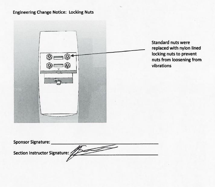
48 APPROVED ELECTRONICALLY 48
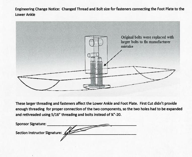
49 APPROVED ELECTRONICALLY 49


50 APPENDIX C: WRITING ASSIGNMENT C1. Material Selection Assignment (Functional Performance) One major component of the design is the foot plate. The foot plate will be the portion of the foot that is in contact with the ground. It is curved in both the front profile and side profile as shown in Figure C1. The curved front profile allows motion normal to the direction of the robot s motion. The curved side profile increases the efficiency of the robot while walking, by transferring the impact force to forward motion. The constraints of the foot plate are size, weight and strength. The size must be approximately that of a human s foot. The weight must be less than 1.3 kg per foot. The material must be strong enough to handle loads of 2000N with a safety factor of at least 3. Figure C1: Foot Plate Design In order to make sure that the foot plate satisfies these requirements we determined that it must have a density of less than 4600 kg/m 3 and yield strength of at least 275 MPa. Using these material indices with the CES software we were able to determine that the top five material choices are boron carbide, PEKK (40% carbon fiber), 6061 aluminum, magnesium ZK60A-F, and beryllium grade S200F. Figure C2: Tope Five Material Choices Determined from CES From these materials we selected 6061 aluminum. We chose aluminum because it is easy to machine, it is readily available and it meets the required material indices. We did not choose carbon fiber because of the difficulty to 50


51 manufacture, boron carbide was eliminated because of the difficulty to machine, magnesium was eliminated because it is not readily available, and we eliminated beryllium because of its high cost. Another major component of the design is the axle. The axle holds the upper ankle to the lower ankle. This is shown in Figure C3. The function of the ankle is to allow for the foot to rotate allowing for the motion produced by the curved front profile of the foot plate. The constraints of the axle are that it must be small enough to fit in the upper ankle while strong enough to handle the large forces produced by the robot s impact. Since the required yield strength for the axle is high, we must ensure that the axle is not too hard so that we will be able to machine it. Figure C3: Axle for Ankle To satisfy the constraints we determine that the axle must have a hardness of 3 GPa on the Vickers hardness scale and a yield strength of at least 200 MPa. Using this material index with the CES software we determined that the top 5 material choices were 1045 steel, 4135 steel, CA-15 stainless steel, 600 nickel-chromium alloy, and Ti-13 titanium alloy. Figure C4: Top Five Material Choices for Axle From these materials we chose 1045 steel because it is the easiest to machine, while still providing the necessary yield strength. 51
52 Mass[g] C2. Material Selection Assignment (Environmental Performance) Two of the options outputted from CES for our foot design were Aluminum and Boron Carbide. We have determined that we will need a mass of one kilogram in order to construct the foot. Using SimaPro we were able to calculate the environmental impact of using each of these materials. Figure C5 below shows the total mass of air emissions, water emissions, soil emissions, and use of raw materials; for both aluminum and boron carbide. The raw material consumption and soil emissions are negligible as compared to the air and water emissions for both of these materials. The calculations determine that the total mass output for aluminum is 7.4*10 15 grams and for boron carbide is 1.1*10 15 grams. These boron carbide output is 34% greater than that of aluminum. Figure C5: Mass of Emissions 9E+15 8E+15 7E+15 6E+15 5E+15 4E+15 3E+15 2E+15 1E+15 0 Raw Air Water Soil Type of emission Aluminum Boron Using the EcoIndicator 99 damage classifications we were able to compare the impact on the environment from each of these materials. Figure C6 relates aluminum to boron carbide in multiple categories. In each category the material with more harmful effect is set to 100% while the other material is compared to it. As can been seen aluminum rates better in all categories except carcinogens, ecotoxicity and minerals. We also used the EcoIndicator to generate a normalized bar graph of the same categories. This graph uses a point value to rate the damage cause in each of the categories. According to Figure C6 the use of raw minerals is the most harmful of the effects, followed by respiratory inorganic and climate change. Lastly we generated Figure C7, which combines the harmful effects of all categories comparing the ecological damage of each of the materials. Based on the bar graph aluminum will have a smaller overall impact on the environment than boron carbide. Based on the results of these four bar graphs we have determined that using Aluminum will have a smaller impact on the environment and therefore will be a better choice for our design. The amount of waste in producing these materials is fairly high so after seeing these results we would consider looking into the effects of carbon fiber on the environment, as it was another option given to us by the CES software. Unfortunately SimaPro does not have carbon fiber in its database therefore we are unable to make this comparison. 52

53 Figure C6: EcoIndicator 99 Characterization of Aluminum and Boron Carbide 53

54 Figure C7: EcoIndicator 99 Normalization of Aluminum and Boron Carbide 54

55 Figure C8: EcoIndicator 99 Total Effect of Aluminum and Boron Carbide 55
56 C3. Manufacturing Process Selection Assignment MABEL is a novel robot, therefore there is no other robot that would require the specialized feet that she requires. Due to the fact that MABEL is attached to a boom and walks in a large circle she requires a degree of freedom in the direction normal to her walking motion. This is something that no other robot requires. Due to these specific characteristics of MABEL we determined our production volume to be a maximum of ten feet. This would provide a pair of feet and backups for Professor Grizzle, as well as create the possibility of other professors or universities joining the research involved with MABEL, allowing them to have their own robot and set of feet to conduct testing on. Using CES software we were able to determine the optimum machining process. By inserting the mass of the materials we needed to shape and necessary shapes CES gave us the following options. Table C1: Optimum Manufacturing Processes Determined via CES Drilling Laser Machining Milling Turning Equipment cost Medium Very High High High Tooling Cost low Low Low Medium Labor Intensity high Low Medium Medium Tolerences 3.1e-5-3.8e-4 5e-6-4e-5 2e-5-5e-4 1.3e-5-3.5e-4 Based on this chart we chose to use milling, turning and drilling operations to complete our prototype, as they were the only viable options that could machine components of the necessary size and required dimension tolerances, and due to the fact that they were available to us in the university machine shop. Milling and drilling were used on the aluminum components of our prototype, while turning was used on our steel shaft. These processes were chosen in accordance to the varying geometries of the components. CNC machines were used for the manufacturing of the complex curves and pockets in the design. If feet were to be produced in higher volumes as mentioned above we determined that CNC machines would be the best option as the same tool paths could be used to produce exact replicas of the feet for each potential MABEL at a reasonable cost. If the feet were machined by hand in high volume there would be high variation in each separate foot, making comparable research difficult. 56
57 APPENDIX D: DETAILED DRAWINGS D1. Attachment Plate 57
58 D2. Rubber Stopper 58

59 D3. Upper Ankle 59
60 D4. Axle 60
61 D5. Lower Ankle 61
62 D6. Foot Plate 62

63 D7. Ankle Bracket 63
Design Project 2 Sizing of a Bicycle Chain Ring Bolt Set ENGR 0135 Sangyeop Lee November 16, 2016 Jordan Gittleman Noah Sargent Seth Strayer Desmond
 1 Design Project 2 Sizing of a Bicycle Chain Ring Bolt Set ENGR 0135 Sangyeop Lee November 16, 2016 Jordan Gittleman Noah Sargent Seth Strayer Desmond Zheng 2 Abstract This report will analyze our calculations,
Analysis of Shear Lag in Steel Angle Connectors
 University of New Hampshire University of New Hampshire Scholars' Repository Honors Theses and Capstones Student Scholarship Spring 2013 Analysis of Shear Lag in Steel Angle Connectors Benjamin Sawyer
Irrigation &Hydraulics Department lb / ft to kg/lit.
 CAIRO UNIVERSITY FLUID MECHANICS Faculty of Engineering nd Year CIVIL ENG. Irrigation &Hydraulics Department 010-011 1. FLUID PROPERTIES 1. Identify the dimensions and units for the following engineering
Design of a double quadruped for the Tech United soccer robot
 Design of a double quadruped for the Tech United soccer robot M.J. Naber (0571509) DCT report number: 2009.134 Master Open Space project Eindhoven, 21 December 2009 Supervisor dr.ir. P.C.J.N. Rosielle
Spring Locomotion Concepts. Roland Siegwart, Margarita Chli, Martin Rufli. ASL Autonomous Systems Lab. Autonomous Mobile Robots
 Spring 2016 Locomotion Concepts Locomotion Concepts 01.03.2016 1 Locomotion Concepts: Principles Found in Nature ASL Autonomous Systems Lab On ground Locomotion Concepts 01.03.2016 2 Locomotion Concepts
GOLFER. The Golf Putting Robot
 GOLFER The Golf Putting Robot Written By Wing Pan Yuen For EEL 5666 Intelligent Machines Design Laboratory December 05, 1999 Table of Contents Abstract Introduction Executive Summary Integrated System
C-Brace Orthotronic Mobility System
 C-Brace Orthotronic Mobility System You ll always remember your first step Information for practitioners C-Brace Orthotics reinvented Until now, you and your patients with conditions like incomplete spinal
Skippy: Reaching for the Performance Envelope
 Workshop on Dynamic Locomotion and Manipulation ETH Zürich, July 2016 Skippy: Reaching for the Performance Envelope Roy Featherstone 2016 Roy Featherstone What is Skippy? a hopping and balancing machine
Humanoid Robots and biped locomotion. Contact: Egidio Falotico
 Humanoid Robots and biped locomotion Contact: Egidio Falotico e.falotico@sssup.it Outline What is a Humanoid? Why Develop Humanoids? Challenges in Humanoid robotics Active vs Passive Locomotion Active
Toward a Human-like Biped Robot with Compliant Legs
 Book Title Book Editors IOS Press, 2003 1 Toward a Human-like Biped Robot with Compliant Legs Fumiya Iida a,b,1, Yohei Minekawa a Juergen Rummel a and Andre Seyfarth a a Locomotion Laboratory, University
Millennial Walker A multi-functional, elderly assistance walker with improved posture, comfort, and folding capabilities.
 Millennial Walker A multi-functional, elderly assistance walker with improved posture, comfort, and folding capabilities. Background & Research Question There are many different styles and categories when
Controlling Walking Behavior of Passive Dynamic Walker utilizing Passive Joint Compliance
 Controlling Walking Behavior of Passive Dynamic Walker utilizing Passive Joint Compliance Takashi TAKUMA, Koh HOSODA Department of Adaptive Machine Systems, Graduate School of Engineering Osaka University
CHAPTER IV FINITE ELEMENT ANALYSIS OF THE KNEE JOINT WITHOUT A MEDICAL IMPLANT
 39 CHAPTER IV FINITE ELEMENT ANALYSIS OF THE KNEE JOINT WITHOUT A MEDICAL IMPLANT 4.1 Modeling in Biomechanics The human body, apart of all its other functions is a mechanical mechanism and a structure,
Design Brief: Problem Statement:
 Design Brief: Problem Statement: The goal of this project is to design a safe, simple, and effective snowboard binding system for a triple amputee who lacks his right arm above the elbow and both legs
Chain Drives. 1. As no slip takes place during chain drive, hence perfect velocity ratio is obtained
 1. Introduction Chain Drives In Belt and Rope drives slipping may occur. In order to avoid slipping, steel chains are used. The chains are made up of a number of rigid links which are hinged together by
Morgan DeLuca 11/2/2012
 Morgan DeLuca 11/2/2012 Telescoping Bicycle Rack for Transit Buses MSDI: TBD Project Description: The goal of this project is to modify the current transit racks to allow for additional bicycles. This
Chain Drives. Chain Drives 759 C H A P T E R
 Chain Drives 759 C H A P T E R 21 Chain Drives 1. Introduction. 2. Advantages and Disadvantages of Chain Drive over Belt or Rope Drive. 3. Terms Used in Chain Drive. 4. Relation Between Pitch and Pitch
Crossed Roller Bearings Series Crossed Roller Bearings Series:
 Crossed Roller Bearings Series Crossed Roller Bearings Series: Proprietary 2V Grinding Technology 102 Crossed Roller Bearing Series: Overview High Precision Bearing Sets Proprietary 2V Grinding Technology
E02 Rigid hinged stinger with piggyback line
 E02 Rigid hinged stinger with piggyback line This model represents a rigid stinger hinged off the back of a lay vessel using the pipelay supports feature. In addition to the lay pipe, another line is included
Creation of a Fallback Catch Method. Megan Berry Mechanical Engineering Senior MAE 490 (4 credits)
") Creation of a Fallback Catch Method Megan Berry Mechanical Engineering Senior MAE 490 (4 credits) Abstract In order that the Cornell Ranger remains autonomous during long distance record attempts and avoids
Creation of a Fallback Catch Method Megan Berry Mechanical Engineering Senior MAE 490 (4 credits) Abstract In order that the Cornell Ranger remains autonomous during long distance record attempts and avoids
EXPERIMENTAL STUDY OF EXOSKELETON FOR ANKLE AND KNEE JOINT
 EXPERIMENTAL STUDY OF EXOSKELETON FOR ANKLE AND KNEE JOINT PROJECT REFERENCE NO. : 37S0925 COLLEGE : NEW HORIZON COLLEGE OF ENGINEERING, BANGALORE BRANCH : MECHANICAL ENGINEERING GUIDES : DR GANESHA PRASAD
Biomechanics and Models of Locomotion
 Physics-Based Models for People Tracking: Biomechanics and Models of Locomotion Marcus Brubaker 1 Leonid Sigal 1,2 David J Fleet 1 1 University of Toronto 2 Disney Research, Pittsburgh Biomechanics Biomechanics
DESIGN AND ANALYSIS OF A COLD GAS PROPULSION SYSTEM FOR STABILIZATION
 DESIGN AND ANALYSIS OF A COLD GAS PROPULSION SYSTEM FOR STABILIZATION AND MANEUVERABILITY OF A HIGH ALTITUDE RESEARCH BALLOON COLLEGE OF ENGINEERING & APPLIED SCIENCES SENIOR DESIGN THESIS GREGORY A. NEFF
Implementing Provisions for Art. 411 of the ICR Ski Jumping
 JUMPING HILLS CONSTRUCTION NORM 2018 Implementing Provisions for Art. 411 of the ICR Ski Jumping Author: Hans-Heini Gasser (SUI) EDITION NOVEMBER 2018 Table of Contents Page 1. Preliminary Remarks 3 2.
In this course you will learn the following
 Module 11 : Example study of robots Lecture 40 : NATARAJ a case study of a 6-legged robot Objectives In this course you will learn the following Mobile Robots Legged Robots Nataraj Robot Nataraj Development
Study to Establish Relations for the Relative Strength of API 650 Cone Roof Roof-to-Shell and Shell-to- Bottom Joints
 Thunderhead Engineering Consultants I N C O R P O R A T E D 1006 Poyntz Ave. Manhattan, KS 66502-5459 785-770-8511 www. thunderheadeng.com Study to Establish Relations for the Relative Strength of API
Walking Simulator Mechanism
 The Downtown Review Volume 2 Issue 2 Article 4 2015 Walking Simulator Mechanism Titus Lungu Cleveland State University Igor Tachynskyy Cleveland State University Omri Tayyara Cleveland State University
Applied Fluid Mechanics
 Applied Fluid Mechanics 1. The Nature of Fluid and the Study of Fluid Mechanics 2. Viscosity of Fluid 3. Pressure Measurement 4. Forces Due to Static Fluid 5. Buoyancy and Stability 6. Flow of Fluid and
EEF. Fatigue Testing Unit PROCESS DIAGRAM AND UNIT ELEMENTS ALLOCATION. Engineering and Technical Teaching Equipment
 Engineering and Technical Teaching Equipment Fatigue Testing Unit EEF PROCESS DIAGRAM AND UNIT ELEMENTS ALLOCATION ISO 9001: Quality Management (for Design, Manufacturing, Commercialization and After-sales
Ranger Walking Initiation Stephanie Schneider 5/15/2012 Final Report for Cornell Ranger Research
 1 Ranger Walking Initiation Stephanie Schneider sns74@cornell.edu 5/15/2012 Final Report for Cornell Ranger Research Abstract I joined the Biorobotics Lab this semester to gain experience with an application
BROCK UNIVERSITY. Name: Student #: Page 1 of 12
 Name: Student #: BROCK UNIVERSITY Page 1 of 12 Final Exam: July 2016 Number of pages: 12 (+ formula sheet) Course: PHYS 1P21/1P91 Number of students: 104 Examination date: 9 July 2016 Number of hours:
Kungl Tekniska Högskolan
 Centre for Autonomous Systems Kungl Tekniska Högskolan hic@kth.se March 22, 2006 Outline Wheel The overall system layout : those found in nature found in nature Difficult to imitate technically Technical
Centre for Autonomous Systems
 Centre for Autonomous Systems Kungl Tekniska Högskolan hic@kth.se March 22, 2006 Outline Wheel The overall system layout : those found in nature found in nature Difficult to imitate technically Technical
Figure 1 Schematic of opposing air bearing concept
 Theoretical Analysis of Opposing Air Bearing Concept This concept utilizes air bearings to constrain five degrees of freedom of the optic as shown in the figure below. Three pairs of inherently compensated
REPORT DOCUMENTATION PAGE
 REPORT DOCUMENTATION PAGE Form Approved OMB NO. 0704-0188 The public reporting burden for this collection of information is estimated to average 1 hour per response, including the time for reviewing instructions,
Friction properties of the face of a hand-held tennis racket
 Available online at www.sciencedirect.com Procedia Engineering 34 (2012 ) 544 549 9 th Conference of the International Sports Engineering Association (ISEA) Friction properties of the face of a hand-held
Precision Rotary Ball Screw
 57E Precision Rotary Ball Screw Models DIR and BLR Outer ring Ball screw nut Deflector Section A Screw shaft Spacer Seal Collar Ball End cap Retainer End cap Ball Screw shaft Outer ring Structure of Standard-Lead
FEA case Study: Rubber expansion joint for piping systems
 FEA case Study: Rubber expansion joint for piping systems Introduction The FEA Toolbox of Taniq makes it possible to simulate the behavior of a pipe expansion joint accurately under several load cases.
Kinterra Instructions for Use Product Number: ROM-00-XXXXX-XX
 Kinterra Instructions for Use Product Number: ROM-00-XXXXX-XX Introduction Patient Selection Assembly Alignment The Kinterra foot/ankle system combines hydraulics and carbon fiber, to provide low to moderate
Structural Design of Tank Weighing Systems
 Structural Design of Tank Weighing Systems 1. Initial observations Some essential rules must be followed when installing load cells in tanks. For example, tanks are frequently subject to weather conditions
Body Stabilization of PDW toward Humanoid Walking
 Body Stabilization of PDW toward Humanoid Walking Masaki Haruna, Masaki Ogino, Koh Hosoda, Minoru Asada Dept. of Adaptive Machine Systems, Osaka University, Suita, Osaka, 565-0871, Japan ABSTRACT Passive
Development of a High Pressure, Oil Free, Rolling Piston Compressor
 Purdue University Purdue e-pubs International Compressor Engineering Conference School of Mechanical Engineering 1994 Development of a High Pressure, Oil Free, Rolling Piston Compressor S. J. Delmotte
Fatigue Analysis of English-Willow Cricket Bat
 Fatigue Analysis of English-Willow Cricket Bat Mr. Rajshekhar Chimmat 1, Mr. Shreenidhi Kulkarni 2 1M.Tech. Scholar, Dept. of Mechanical Engineering, KLS Gogte Institute of Technology, Belagavi, Karnataka,
Ergonomic Handle for a 2DoF Robotic Hand Rehabilitation Device
 Ergonomic Handle for a 2DoF Robotic Hand Rehabilitation Device Design Team Steven Adams, Kyle Hackmeister Lucas Johnson, Daniel Lau, Nicholas Pappas Design Advisor Prof. Constantinos Mavroidis Co-Advisors
IAC-04-IAA DESIGN OF A HIGH-TENSION ELASTICALLY DEFORMING SPACE TETHER DEPLOYER
 IAC-04-IAA-3.8.2 DESIGN OF A HIGH-TENSION ELASTICALLY DEFORMING SPACE TETHER DEPLOYER Bas Lansdorp, MSc Delft University of Technology, The Netherlands bas.lansdorp@lr.tudelft.nl Prof. ir. H.M.J.R. Soemers
Hub Bearings for Automobiles that Conserve Resources
 New Product Hub Bearings for Automobiles that Conserve Resources Isao HIRAI Automotive parts are being expected to respond to environmental issues such as global warming and to effectively use natural
Effects of Changes of Spokes in the Operation of a Rimmed Flywheel
 Effects of Changes of Spokes in the Operation of a Rimmed Flywheel M M 1, Ramachandra N K 2, Shruthi RP 3 1 Asst. Professor, Dept. of Mechanical Engineering, T.JOHN Institute of Technology,B lore-83 2
Inflatable Standing Aid Device
 Inflatable Standing Aid Device Design Team Travis Fulton, Megan McGuire James O Keefe, Justin Tichy, David Venturoso Design Advisor Prof. Andrew Gouldstone Abstract The purpose of this project is to design
Sprocket Selection Guidelines
 Sprocket Selection Guidelines Table 1 Information Necessary to Order Sprockets 1. Chain Size Number, type, or drawing number of the chain to be used on the sprocket. (The suitability of a sprocket depends
Load Ring bolted > VWBG < in pink
 RUD-Art.-Nr.: 8503693-EN / 03.014 Load Ring bolted > VWBG < in pink EN Safety instructions This safety instruction/declaration has to be kept on file for the whole lifetime of the product. Translation
INTRODUCTION TABLE OF CONTENTS
 2 INTRODUCTION Thank you for choosing Servometer to design and manufacture your unique, new electrodeposited bellows for your particular application. The definitions, formulas and design parameters inside
AIRMOUNT VIBRATION ISOLATION
 MOUNT VIBRATION ISOLATION SELECTION AND ISOLATION FORMULA Refer to the selection guide on page 33 for Airmount load and isolation capabilities. Follow this procedure: 1. LOAD CAPACITY Select one or two
Tightening Evaluation of New 400A Size Metal Gasket
 Proceedings of the 8th International Conference on Innovation & Management 307 Tightening Evaluation of New 400A Size Metal Gasket Moch. Agus Choiron 1, Shigeyuki Haruyama 2, Ken Kaminishi 3 1 Doctoral
Design of a Solid Wall Transonic Wind Tunnel
 Design of a Solid Wall Transonic Wind Tunnel David Wall * Auburn University, Auburn, Alabama, 36849 A solid wall transonic wind tunnel was designed with optical access from three sides to allow for flow
- a set of known masses, - four weight hangers, - tape - a fulcrum upon which the meter stick can be mounted and pivoted - string - stopwatch
 1. In the laboratory, you are asked to determine the mass of a meter stick without using a scale of any kind. In addition to the meter stick, you may use any or all of the following equipment: - a set
ZIPWAKE DYNAMIC TRIM CONTROL SYSTEM OUTLINE OF OPERATING PRINCIPLES BEHIND THE AUTOMATIC MOTION CONTROL FEATURES
 ZIPWAKE DYNAMIC TRIM CONTROL SYSTEM OUTLINE OF OPERATING PRINCIPLES BEHIND THE AUTOMATIC MOTION CONTROL FEATURES TABLE OF CONTENTS 1 INTRODUCTION 3 2 SYSTEM COMPONENTS 3 3 PITCH AND ROLL ANGLES 4 4 AUTOMATIC
Kintrol Instructions for Use Product Number: VS4
 Kintrol Instructions for Use Product Number: VS4 Introduction The Kintrol foot/ankle combines hydraulics and fiberglass to provide K2 ambulators an exceptionally normal walking gait regardless of surface
CHAPTER 18 UNIVERSITY OF WISCONSIN- MILWAUKEE
 CHAPTER 18 UNIVERSITY OF WISCONSIN- MILWAUKEE College of Health Sciences Department of Occupational Therapy 212 Hartford Avenue Milwaukee, Wisconsin 53211 College of Engineering and Applied Sciences 3200
Reinforced Soil Retaining Walls-Design and Construction
 Lecture 32 Reinforced Soil Retaining Walls-Design and Construction Prof. G L Sivakumar Babu Department of Civil Engineering Indian Institute of Science Bangalore 560012 Example calculation An 8 m high
From Constraints to Components at Marin Bicycles
 From Constraints to Components at Marin Bicycles A Case Study for The Mechanical Design Process Introduction This case study details the development of the Marin Mount Vision Pro mountain bicycle rear
The BIG BOOK of Golf Drills
 The BIG BOOK of Golf Drills 1 How to Use This Guide Congratulations on purchasing the Big Book of Golf Drills! This book is designed to use as a reference guide. We do not recommend printing this out as
Something had to be done. We did it.
 Something had to be done. We did it. Motion Composites believes in empowering wheelchair users. Why? Because clunky and inefficient equipment is unfortunately too common. Which means you re less mobile
SECOND ENGINEER REG III/2 NAVAL ARCHITECTURE
 SECOND ENGINEER REG III/2 NAVAL ARCHITECTURE LIST OF TOPICS A B C D E F G H I J Hydrostatics Simpson's Rule Ship Stability Ship Resistance Admiralty Coefficients Fuel Consumption Ship Terminology Ship
GO BEYOND! If you have had enough of bulky, inefficient equipment, try the Helio C2 HD!
 GO BEYOND! Why limit yourself with heavy equipment when you don t have to? At Motion Composites, we have taken the heavy out of heavy duty! The Ultralight C2 HD has an increased weight capacity of 350
Development of an end-effector to simulate the foot to ball interaction of an instep kick in soccer
 Available online at www.sciencedirect.com Procedia Engineering 34 (2012 ) 284 289 9 th Conference of the International Sports Engineering Association (ISEA) Development of an end-effector to simulate the
Mechanisms: The different motions we could produce by using different mechanisms were brainstormed. Some of these mechanisms were sketched above.
 Brainstorming: Early on we decided on constructing an automaton. While this is a toy and not a game, it was decided that an esthetically interesting toy would be more intriguing than a game with few moving
5. A bead slides on a curved wire, starting from rest at point A in the figure below. If the wire is frictionless, find each of the following.
 Name: Work and Energy Problems Date: 1. A 2150 kg car moves down a level highway under the actions of two forces: a 1010 N forward force exerted on the drive wheels by the road and a 960 N resistive force.
Aeris Performance 2. Product Manual
 Aeris Performance 2 Product Manual Instructions The Aeris Performance 2 is designed to be maintenance free. The foot is water resistant; however, if the foot is submerged in water, the foot and foot shell
Tri-Better Detailed Design Review
 Tri-Better Detailed Design Review Designers: Michael Kurvach Nathaniel Morefield Ryan Wilson Cody Woods Guide: Dr. Richard Lux Project Overview The goal of this project is to create a shoe and pedal which
Simulation of the Hybtor Robot
 Simulation of the Hybtor Robot Pekka Aarnio, Kari Koskinen and Sami Salmi Information and Computer Systems in Automation Helsinki University of Technology ABSTRACT A dynamic rigid body simulation model
PERCEPTIVE ROBOT MOVING IN 3D WORLD. D.E- Okhotsimsky, A.K. Platonov USSR
 PERCEPTIVE ROBOT MOVING IN 3D WORLD D.E- Okhotsimsky, A.K. Platonov USSR Abstract. This paper reflects the state of development of multilevel control algorithms for a six-legged mobile robot. The robot
Tapered Roller Bearings in X-life quality Customer Information. Business Unit TRB Schweinfurt, 2013
 Tapered Roller Bearings in X-life quality Customer Information Business Unit TRB Schweinfurt, 2013 X-life roll-out BU TRB Agenda Tapered Roller Bearings in X-life quality 1 2 3 4 X-life what is it? X-life
Structure (Down plane)
") By Lauren Russell Structure (Down plane) The body (toes, knees, hips, wrists and shoulders) is aligned parallel to the intended target line. The torso is tilted over the ball from the hips whilst maintaining
By Lauren Russell Structure (Down plane) The body (toes, knees, hips, wrists and shoulders) is aligned parallel to the intended target line. The torso is tilted over the ball from the hips whilst maintaining
Level 3 Cambridge Technical in Engineering 05822/05823/05824/05825/05873 Unit 3: Principles of mechanical engineering
 Level 3 Cambridge Technical in Engineering 05822/05823/05824/05825/05873 Unit 3: Principles of mechanical engineering Monday 16 January 2017 Afternoon Time allowed: 1 hour 30 minutes You must have: the
Coaching Principles. 1. Introduce 2. Demonstrate 3. Explain 4. Organize 5. Execute 6. Correct 7. Practice
 5 Pin Bowling Drill Book Updated August 2008 Coaching Principles STEPS IN TEACHING A DRILL 1. Introduce 2. Demonstrate 3. Explain 4. Organize 5. Execute 6. Correct 7. Practice GENERAL PRINCIPLES Drills
The Soccer Guy. By Marcus Hilgers Faisal Ahmad Jacob Borer
 The Soccer Guy By Marcus Hilgers Faisal Ahmad Jacob Borer 1.0 Abstract The Soccer Guy automaton was created to provide a fun, interactive, simple game. It uses simple mechanical and computational elements
Paint Brush Handle. Julia Carlson Heather Curtin Julia Hamlin. Western Washington University. March 12, 2003
 Paint Brush Handle Julia Carlson Heather Curtin Julia Hamlin Western Washington University March 12, 2003 Society of Plastics Engineers Blow Molding Division 2003 Student Design Competition Recycled Paintbrush
Spanish Ski School. Association of Schools, Professors and Trainers of Winter Sports
 Interski 20 th Congress - Ushuaia 2015 Spanish Ski School Association of Schools, Professors and Trainers of Winter Sports Evolution of carving revolution: A turning point to knee injuries prevention?
Sample Solution for Problem 1.a
 Sample Solution for Problem 1.a 1 Inverted Pendulum Model (IPM) 1.1 Equations of Motion and Ground Reaction Forces Figure 1: Scheme of the Inverted Pendulum Model (IPM). The equations of motion of this
2 Available: 1390/08/02 Date of returning: 1390/08/17 1. A suction cup is used to support a plate of weight as shown in below Figure. For the conditio
 1. A suction cup is used to support a plate of weight as shown in below Figure. For the conditions shown, determine. 2. A tanker truck carries water, and the cross section of the truck s tank is shown
OPTIMAL TRAJECTORY GENERATION OF COMPASS-GAIT BIPED BASED ON PASSIVE DYNAMIC WALKING
 OPTIMAL TRAJECTORY GENERATION OF COMPASS-GAIT BIPED BASED ON PASSIVE DYNAMIC WALKING Minseung Kim Dept. of Computer Science Illinois Institute of Technology 3201 S. State St. Box 2082 Chicago IL 60616
MOTION FOOT MX. Manual
 MOTION FOOT MX Manual Real Technology - Real People CONTENTS Intruduction....4 Patient Selection....4 Foot Components....4 Special Precautions....5 Set-Up....6 Change Heel Height & Dorsi Flexion Range....
Volume 2, Issue 5, May- 2015, Impact Factor: Structural Analysis of Formula One Racing Car
 Structural Analysis of Formula One Racing Car Triya Nanalal Vadgama 1, Mr. Arpit Patel 2, Dr. Dipali Thakkar 3, Mr. Jignesh Vala 4 Department of Aeronautical Engineering, Sardar Vallabhbhai Patel Institute
A NEW GOLF-SWING ROBOT MODEL UTILIZING SHAFT ELASTICITY
 Journal of Sound and Vibration (1998) 17(1), 17 31 Article No. sv981733 A NEW GOLF-SWING ROBOT MODEL UTILIZING SHAFT ELASTICITY S. SUZUKI Department of Mechanical System Engineering, Kitami Institute of
Offshore platforms survivability to underwater explosions: part I
 Computational Ballistics III 123 Offshore platforms survivability to underwater explosions: part I A. A. Motta 1, E. A. P. Silva 2, N. F. F. Ebecken 2 & T. A. Netto 2 1 Brazilian Navy Research Institute,
Anemometry. Anemometry. Wind Conventions and Characteristics. Anemometry. Wind Variability. Anemometry. Function of an anemometer:
 Anemometry Anemometry Function of an anemometer: Measure some or all of the components of the wind vector In homogeneous terrain, vertical component is small express wind as -D horizontal vector For some
STRESS ANALYSIS OF BICYCLE PADDLE AND OPTIMIZED BY FINITE ELEMENT METHOD. S. Abeygunasekara 1, T. M. M. Amarasekara 2
 - 96 - STRESS ANALYSIS OF BICYCLE PADDLE AND OPTIMIZED BY FINITE ELEMENT METHOD S. Abeygunasekara 1, T. M. M. Amarasekara 2 1 Faculty of Engineering & Technology, Colombo International Nautical Engineering
Materials : Dichromate zinc plated steel flanges
 Size : Ends : Min Temperature : Max Temperature : DN 25 to 300 Flanges PN10/16-35 C + 130 C Max Pressure : 16 Bars up to DN150, 10 bars over Specifications : Absorb vibrations and noise Linear and angular
DX2/DXX Operating Instructions
 CHECK LINE BY ELECTROMATIC DX2/DXX Operating Instructions CHECK LINE INSTRUMENTS ELECTROMATIC E Q U I P M E N T C O., I N C. 600 Oakland Ave., Cedarhurst, NY 11516 U.S.A. TEL: 516-295-4300 FAX: 516-295-4399
Autodesk Moldflow Communicator Process settings
 Autodesk Moldflow Communicator 212 Process settings Revision 1, 3 March 211. Contents Chapter 1 Process settings....................................... 1 Profiles.................................................
POTENTIAL ENERGY AND ENERGY CONSERVATION
 POTENTIAL ENERGY AND ENERGY CONSERVATION 1. Sky Jump: You have landed a summer job with a company that has been given the contract to design the ski jump for the next Winter Olympics. The track is coated
Tension Cracks. Topics Covered. Tension crack boundaries Tension crack depth Query slice data Thrust line Sensitivity analysis.
 Tension Cracks 16-1 Tension Cracks In slope stability analyses with cohesive soils, tension forces may be observed in the upper part of the slope. In general, soils cannot support tension so the results
Your Life. Your Adventure. Triton Family of Products
 Your Life. Your Adventure. Triton Family of Products Ready for any challenge The search is over! Now your high-mobility patients can choose from a variety of superb options to fit their active lifestyles.
Appendix : Categorization Task. Instructions
 Appendix : Categorization Task Instructions Your task is to group the 25 problems below based upon similarity of solution into various groups on the sheet of paper provided. Problems that you consider
IAI WARNING! INSTRUCTION MANUAL TO REDUCE THE RISK OF INJURY, USER MUST READ AND UNDERSTAND THIS INSTRUCTION MANUAL. ORIGINAL INSTRUCTIONS
 INSTRUCTION MANUAL IAI WARNING! TO REDUCE THE RISK OF INJURY, USER MUST READ AND UNDERSTAND THIS INSTRUCTION MANUAL. ORIGINAL INSTRUCTIONS Date of purchase:.......... SM-6 Manual.en 04/2016 SSM ProduktAB
Modeling of Hydraulic Hose Paths
 Mechanical Engineering Conference Presentations, Papers, and Proceedings Mechanical Engineering 9-2002 Modeling of Hydraulic Hose Paths Kurt A. Chipperfield Iowa State University Judy M. Vance Iowa State
Computer Aided Drafting, Design and Manufacturing Volume 26, Number 2, June 2016, Page 53. The design of exoskeleton lower limbs rehabilitation robot
 Computer Aided Drafting, Design and Manufacturing Volume 26, Number 2, June 2016, Page 53 CADDM The design of exoskeleton lower limbs rehabilitation robot Zhao Xiayun 1, Wang Zhengxing 2, Liu Zhengyu 1,3,
Motion Control of a Bipedal Walking Robot
 Motion Control of a Bipedal Walking Robot Lai Wei Ying, Tang Howe Hing, Mohamed bin Hussein Faculty of Mechanical Engineering Universiti Teknologi Malaysia, 81310 UTM Skudai, Johor, Malaysia. Wylai2@live.my
Scissor Mechanisms. Figure 1 Torero Cabin Service Truck. Scissor Mechanism was chassis mounted and lifted the cabin to service aircraft
 Scissor Mechanisms Scissor mechanisms are very common for lifting and stabilizing platforms. A variety of manlifts, service platforms and cargo lifts utilize this visually simple but structurally complex
DESIGN OPTIMIZATION OF WORK ROLL CHOCK AND BACKUP ROLL CHOCK IN COLD ROLLING MILL
 DESIGN OPTIMIZATION OF WORK ROLL CHOCK AND BACKUP ROLL CHOCK IN COLD ROLLING MILL Tukesh Sahu 1, Prof. G.R.Kesheory 2 1M.Tech Scholar, Department of Mechanical Engineering, VITS Indore, MP, India 2Assistant