Before you start! Is iwalk 2.0 right for you?
|
|
|
- Ella Powell
- 5 years ago
- Views:
Transcription
1
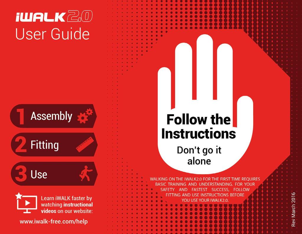
2 Before you start! Is iwalk 2.0 right for you? Physical Abilities Requirements 1. Stair Test Before your injury, could you easily walk up and down stairs at normal speed, without using the hand rail? 2. Balance Test Can you balance on one foot for at least 30 seconds? If you cannot perform both of these tests, then iwalk2.0 is not going to work for you. Please contact us for a return authorization number. If you can perform both, then continue reviewing the remaining requirements. Other Requirements You commit to reading and following all of the instructions in this manual or in our video tutorials at You're willing to allow 5-20 minutes to allow your body to learn and adapt to using the iwalk2.0 Before your injury, you could walk normally without assistive devices Your injury is below the knee and your uninjured leg is fully functional You can bend your injured leg 90 degrees at the knee Sizing Limitations Height - You are between 4'10" and 6'6", however, leg length proportions vary considerably, so if you are under 5'1" and above 6'1" consult our sizing chart on page 3 You weigh 275lbs (125kg) or less Your thigh circumference at the top of your leg is 28" (71cm) or less Age Limits If you're over 55, pay careful attention - iwalk2.0 might not work for you. Physical ability is more important than how old you are. And it varies from person to person, especially as we age. So regardless of your age, if you do not meet ALL the requirements listed above, then iwalk2.0 isn't going to work for you. If you meet the requirements listed above, iwalk2.0 will work for you. More details on qualifications can be found at

3 iwalk 2.0 SIZE CHART - based on user's height 4 10 to to to cm to cm cm to cm cm to cm Review the Leg Length Diagram below. The iwalk2.0 will fit you. Review the Leg Length Diagram below. If your height falls into either of the blue sections in the chart on the left, there s a 95% or greater chance the iwalk2.0 will fit you, but before you buy, confirm it will fit using the Leg Length Chart below. iwalk 2.0 SIZE CHART - based on user's leg length Still not sure? If you are not certain that iwalk2.0 is right for you, contact our technical support at or your inquiry to info@iwalk-free.com IWALK 2.0 LEG LENGTH DIAGRAM Side Upper Leg Length min (30.5 cm) max (46.0 cm) Lower Leg Length min (35.0 cm) max (51.0 cm) Front Leg Length (Crotch to floor) min (65.5 cm) max (96.5 cm) Extra links: More info about sizing Why do Upper and Lower leg lengths matter? iwalk2.0 Capacities Potential Knee Comfort Issues Measure both upper and lower leg as shown. If you fall within the ranges shown, iwalk2.0 will fit you, no matter what your height is.
4 LEARN TO USE YOUR iwalk 2.0 IN 3 EASY STEPS 1 ASSEMBLY 5 to 7 2 FITTING 8 to 17 3 USE 18 to 25 Repackaging 26 to 30 Index 4
 5. Height Adjustment Spring Upper 6. Gate Strap 7. Support Tubes 8. Clamp 8a. Clamp Bolt 8b.")


5 Assembly Instructions 9. Thigh Strap 10. Knee Strap 11. Calf Strap 12. Knee Platform 13. Calf Strap Mount 14. Height Adjustment Spring Lower 15. Foot 1. Thigh Support 2. Thumb Screws 3. Handle 4. Nut (underside thigh support) 5. Height Adjustment Spring Upper 6. Gate Strap 7. Support Tubes 8. Clamp 8a. Clamp Bolt 8b. Clamp Nut Upper Assembly Lower Assembly WANT TO LEARN FASTER? View our instructional video on how to assemble your iwalk2.0 at STEP 1 With the Handle facing forward, insert the Upper Assembly tubes into the sockets of the Knee Platform. Push down firmly on the Handle to make sure both tubes are fully bottomed out in the sockets. You may have to pull down on the left side tube in order for it to reach the bottom. Make sure that the holes at the bottom of the tubes align with the holes in the side of the Knee Platform. You may need to pull down and/or rotate the left side tube for it to align. WARNING do not continue with assembly unless both left and right side holes have aligned. Assembly 5


 Test the connection by firmly grasping the Upper Assembly tube with one hand and")

6 STEP 2 STEP 3 A B C A) Identify the Right side Support Tube by the small R stamped near the top. B) While pushing down on the Upper Assembly tube, press in the silver spring head and insert the Support Tube into the bottom of the Knee Platform socket until the spring head engages in the holes of the Upper Assembly tube AND the Knee Platform. All three must be locked together. Attach the Lower Assembly to the Knee Platform by pressing in the spring head at the top of the Lower Assembly tube and inserting the tube into the socket of the Knee Platform. Grasping the tube, pull down forcibly to insure that the two parts are securely locked together. C) Test the connection by firmly grasping the Upper Assembly tube with one hand and the Support Tube with the other and forcibly try to pull them apart. If you cannot pull them apart, you have assembled the three components correctly. D) Insert the Left side Support Tube using the same procedures. You may need to rotate the tube in order to align the hole. WARNING Aggressively test both connections (left and right). If the Support Tube, Knee Platform and Upper Assembly tubes are not locked together, instability and injury can result. Assembly 6


7 STEP 4 STEP 5 The Clamp should be positioned between the flat ends of the Support Tubes. If not, you can remove the Support Tube and reinstall. Gently push on the ends of the Support Tubes to align the holes with the hole on the Clamp, then insert the Clamp Bolt and secure with the Clamp Nut. Do not tighten yet. Insert the Thumb Screw into the slot on either side of the top of the Handle. Align the hole in the top of the Thigh Support with the threaded end of the Thumb Screw. Thread the Thumb Screw into the nut located on the underside of the Thigh Support (you can see it from underneath). Do not fully tighten yet, you should be able to rotate the Thigh Supports in and out. Thumb Screw Nut Note Clamp should be centered between the Support Tube ends. Realign if necessary using a screwdriver or similar. Note If the Thumb Screw will not fully tighten, check the underside of the Thigh Support and make sure there is a silver nut nested in the hex shaped cavity. Be careful not to accidentally push this nut out when pushing the Thumb Screw down. If you lose the nut, don t panic you can call us for a replacement or find one at a local hardware store. The specification is M5 x.8 (metric, 5mm,.8 pitch) Assembly 7


8 Fitting Instructions WANT TO LEARN FASTER? View our instructional video on how to fit your iwalk2.0 at Proper fit is essential! But it s also easy. Get these three things right and you ll be iwalking in minutes. We ll show you how. STEP 1 Make sure that Thigh Supports can rotate freely. If necessary, loosen Thumb Screws. Height Adjust both the upper and lower section of the crutch to the correct height. Tight For control and stability, you want the straps tight! Really, really tight! Vertical Alignment Essential for quick learning, and often overlooked, the vertical angle controls where the foot will be positioned. Fitting 8


9 Foot Positioning (for Left or Right) - Position the Foot so that the curved edge is toward the outside of your leg. To reposition the foot, Right Foot 1. Loosen the Clamp Bolt. 2. Press in the height adjustment springs as shown below. 3. Continue pressing; simultaneously grasp and rotate the Foot 180 degrees until the spring heads pop out of the adjustment holes. Note - The Foot and lower tube will rotate. The upper tube stays stationary. Incorrect Correct STEP 2 Left Foot Incorrect Correct Loosen Clamp Bolt first 180 Improper orientation of the Foot causes instability which could result in a fall and/or injury. Fitting 9

 Loosen the Clamp Nut and Bolt. B) Press in the two silver spring heads.")


10 A B C Loosen Clamp Bolt STEP 3 Lower Leg Height Adjustment - The V at the back of the Knee Platform should align with a point ½ 1 below the bottom of your kneecap. This will result in your iwalk leg being slightly shorter than your human leg. If in doubt about the correct height setting, it s better to adjust the crutch slightly too low than too high. To adjust the height: A) Loosen the Clamp Nut and Bolt. B) Press in the two silver spring heads. Grasp the Foot and rotate slightly back and forth while pulling or pushing to the desired length. When both spring heads are fully engaged in their new position, tighten the Clamp Nut and Bolt. C) Confirm correct height setting before proceeding. Note After you gain basic proficiency, you will readjust the lower leg height to achieve equal leg length. Before putting weight on the crutch, make certain that both spring heads are fully engaged ( popped out ) in the adjustment holes. Then tighten the Clamp Bolt. Failure to do so could result in a fall and / or injury. Fitting 10


11 Upper Leg Height Adjustment Press the push button spring head and pull up on the Handle until the Thigh Supports are as high as possible on your leg. Make sure the spring head pops all the way out of the hole to lock in your setting. Note If the spring head will not pop out, twist the Handle back and forth until it engages fully. STEP 4 STEP 5 Positioning the Thigh Supports lower than the top of the leg will reduce stability and efficiency. CORRECT X INCORRECT Grasping the Handle, kneel on the crutch with the crutch Foot and your human foot side by side, shoulder width apart. On a hard, level surface, grasping the Handle and correctly positioned with feet side by side, shoulder width apart, kneel on the crutch so that you have equal weight on both legs. The crutch should automatically assume a slight outward tilt. Shoulder width 50% 50% WEIGHT DISTRIBUTION 1. The goal is to position the crutch Foot where your human foot would normally be. 2. Most people will automatically shift their weight to their good leg, so you need to continually monitor this. Keep your weight evenly distributed on both legs. Fitting 11


12 Positioning the Crutch Position your knee as far forward as possible, and move the Handle laterally across your leg to help achieve the correct angle. Remember to keep 50/50 weight distribution during this step. STEP 6 When properly fitted, the crutch should be angled slightly outward as shown below. Achieving the correct angle is automatic if you follow our instructions. The goal is to position the crutch so that the crutch Foot is located where your human foot would normally be. Once you have the crutch at the correct angle, hold this position and proceed to Step 7. CORRECT Slight outward angle X INCORRECT Outward angle X INCORRECT No angle X INCORRECT Inward angle Fitting 12

 Rotate the OUTER Thigh Support until it contacts your")


13 Thigh Supports Adjustment A) Rotate INNER Thigh Support until it contacts your thigh, then rotate it another inch or so. Lock it down securely using the Thumb Screw. B) Rotate the OUTER Thigh Support until it contacts your outer thigh. Lock it down securely with the Thumb Screw. A Inner thigh USER'S THIGH B USER'S THIGH Outer thigh STEP 7 Note - Thigh Support adjustment affects both sizing and vertical alignment of the crutch. If you are straight legged, adjust your Thigh Supports symmetrically. If you are Valgus (knock kneed) or Varus (bow legged), you will adjust the Thigh Supports asymmetrically to tilt the crutch in the proper direction. Correct vertical alignment is essential to the crutch working correctly. Example shows adjustment sequence for Right leg STRAIGHT LEG VALGUS (KNOCK KNEED) VARUS (BOW LEGGED) USER S THIGH Fitting 13

14 Straps Adjustment Before you adjust the straps, you need to understand how they work. There are two distinct sections. The Length Adjustment section and the Tighten/ Loosen section. See details below. Length Adjustment Section This section has BLACK buckles on either end. Used only for adjusting the length of the strap to fit your leg circumference. Not used for final tightening of the strap. For this, use TIGHTEN and LOOSEN section at right. Tighten / Loosen Section This section has GRAY buckles on either end. Used only for TIGHTENING and LOOSENING of the strap. TIGHTEN FULLY to achieve maximum strap tension before using the crutch. LOOSEN for easy buckle removal (when taking the crutch off). To shorten or tighten the Strap, pull on the end of the strap as shown above. To lengthen or release the Strap, lift up on the end of the buckle. Fitting 14


 of the Straps.")


 Slide the Strap mounts to the back")

")


15 Different Buckle Types T Lock Buckles are located at the ends of the Straps. They are used to attach the Straps to the crutch. Tensionlock Buckles are used to adjust the length (and tension) of the Straps. Each Strap has two T Lock buckles and two Tensionlock buckles. T Lock Buckles Tensionlock Buckles Strap Installation Before installing the Straps extend both the LENGTH ADJUSTMENT and the TIGHTEN LOOSEN sections to their maximum length. A) Slide the Strap mounts to the back of the Knee Platform. Strap mounts can slide forward if alternate positioning is needed. A As far back as possible STEP 8 B) Install the black T Lock buckles onto the crutch on the inner leg side as shown at right. Do not install the gray buckles yet. Leave the Straps hanging for now. B C C) Lock the buckles as shown at far right. Left Foot Right Foot Fitting 15

 Fully tension the strap using the TIGHTEN / LOOSEN SECTION. Pull on the tail of the webbing until the Strap is extremely tight.")
, then shorten the")

16 Strap Adjustment and Tightening A B C D STEP 9 A) Position your leg on the Knee Platform. Make certain you are as far forward as possible. Drape the Strap over the back of your knee and fasten the Gray buckle onto the Knee Platform. B) Adjust the length of the strap by pulling on the end of the LENGTH ADJUSTMENT SECTION. Pull until the strap is snug, but not fully tensioned. C) Fully tension the strap using the TIGHTEN / LOOSEN SECTION. Pull on the tail of the webbing until the Strap is extremely tight. Hint - if you can slip a finger under the strap, it's too loose. If you cannot achieve the required tension, loosen the TIGHTEN / LOOSEN section (lift up on the end of the tensionlock buckle), then shorten the length using the LENGTH ADJUSTMENT SECTION, then re-tighten using TIGHTEN / LOOSEN section. D) Repeat for upper thigh Strap and calf Strap. Reposition strap pads if needed. When we say tight, we mean it. Seriously, tighten those straps down. If they're not super tight, don't even use the crutch. Properly tightened straps make it so much easier to learn and use the iwalk2.0. The goal is to make the crutch an integral part of your leg. Fitting 16


17 To remove the crutch, you need to loosen the Straps first. Starting with the calf Strap, lift the lip of the Gray Tensionlock buckle. This will loosen the Strap enough that you can push forward on the Gray T Lock buckle. Next, do the upper thigh Strap, and do the knee Strap last. STEP 10 To remove the crutch, (A) lift up on the buckles as shown to release Strap tension, then (B) push forward on the T Lock buckle to release from the crutch. Fitting 17


18 Use Instructions WANT TO LEARN FASTER? View our instructional video on how to use your iwalk2.0 at If properly fitted, learning to walk with your iwalk2.0 is easier than you think, provided that you follow our instructions. People learn at different rates some people can walk in the first couple minutes, but others can take longer. It s important that you are willing to spend up to thirty minutes to allow yourself to adapt to the device. Pre-iWALK safety check list: Proper fit is ESSENTIAL. Fit 1. Height You want the height to be correct. See steps 5 through 7 in the Fitting section 2. Tight Eliminate all unwanted movement of the crutch by making sure that all three straps are extremely tight. See steps 8 and 9 in the Fitting section of this manual. 3. Vertical Alignment - Correct vertical alignment of the crutch to match your leg type is essential. Correct alignment will place the crutch foot approximately where your human foot would normally be. This provides you with a natural, familiar balancing point. Review step 6 in the Fitting section to ensure that you have made the correct adjustments. 4. Your want the iwalk Foot positioned approximately where your human foot would have been. See Step 5 in the Fitting section. Height Tight Vertical Alignment Use 18

 Feet side by side, approximately shoulder width apart B) Weight EVENLY DISTRIBUTED between")
19 Environment Find a hard, level surface that allows you to walk in a straight line for as far as possible. There should be no obstacles to navigate. Avoid uneven surfaces or padded carpets when learning. An ideal environment would allow you to take at least 20 steps before turning. A hallway or long balcony are examples of good environments for learning to iwalk. X Starting Position Before you start walking, you always want to be in the starting position, which is: A) Feet side by side, approximately shoulder width apart B) Weight EVENLY DISTRIBUTED between your human leg and your iwalk leg. This is essential for normal balance and control. A B 50% 50% Weight distribution Walk As Normal As Possible The iwalk 2.0 is easy to learn and very efficient because it uses most of the natural instincts you already use for walking. The more you try to walk normally, the better it will work. The adaptation from normal gait to iwalk gait is minor, so your body already knows how to walk on it. Try not to over adapt or over think it. Use 19


20 Before You Start: How To Avoid the Common Mistakes 1. Look up. A human head weighs over ten pounds, so rocking it forward to watch the ground throws off your natural balance. Also, you don t normally look down while walking, so don t do that when iwalking. Hint - look at an object in the distance and keep your eyes locked on it. 2. Commit your weight to the crutch. When you are bringing your good foot from back to front (swing gait), all of your weight will be on your iwalk crutch. Most beginners rush to get their good foot back down, but this makes it harder to learn. Trust the crutch, commit all your weight to it, just as you would your normal leg. 3. Maintain forward momentum. When we walk, we put our body mass in front of our feet. We re actually falling forward, but we don t fall because we instinctively catch ourselves by stepping forward. The iwalk crutch exploits these instincts. If you don t commit to moving your body forward, ahead of your feet, you can t walk X Foot Mass Use 20

 Position yourself in the start position, feet side by side,")
 Grasping the Handle, lean the crutch forward while you simultaneously")
 You will instinctively step forward with your good foot.")
 Stop, step back and return to the start position.")
21 Let s get started: START POSITION STEP 1 50% 50% WEIGHT DISTRIBUTION A A Begin from Start position Step forward with good leg then STOP B Lean forward C D Return to Start Position by stepping back with good foot Practice: A) Position yourself in the start position, feet side by side, shoulder width apart, weight distributed 50 / 50. B) Grasping the Handle, lean the crutch forward while you simultaneously bring your upper body forward of your feet. C) You will instinctively step forward with your good foot. Take this step, but don't step forward with the crutch Foot yet. D) Stop, step back and return to the start position. Repeat this exercise at least four times, until you are very comfortable stepping forward and stepping back. Use 21
 Position yourself in the starting position.")

 If you stop, return to the start position before resuming.")
22 STEP 2 Start Walking: Start Position Lean Forward Step forward with good leg Step with iwalk leg A B C D A) Position yourself in the starting position. B) Following the same routine as you did in practice, this time, continue walking with your crutch leg. C) Maintain momentum as long as your environment allows - try to keep iwalking without stopping. D) If you stop, return to the start position before resuming. Follow the same routine to start iwalking again. Use 22
 to remind yourself to commit all your weight to the crutch.")

23 Tip 1 - If your good leg feels significant fatigue, it s a sure indication that you are not committing all your weight to the crutch. This is a common mistake, and will slow your progress. Pushing down hard on the handle (when your weight is on the crutch leg) to remind yourself to commit all your weight to the crutch. Tip 2 - Keep walking without stopping and you will rapidly improve as your body recognizes the gait adaptation. As soon as possible, let go of the Handle and let your arms swing naturally. Most people will be hands free in the first couple minutes. STEP 3 Retighten the Straps After a few steps, retighten the Straps. For proper control and balance, we cannot overemphasize how important it is to properly tension the straps. If you cannot get the straps fully tightened, readjust the length by following the provided instruction in the Fitting section. Use 23

 Lengthen the Lower Leg Height Adjustment to achieve equal leg length (see Fitting Section, Step 3).")
24 Change Adjustment Settings Learning Settings So far you have been in the Learning Settings (crutch leg length slightly shorter than human leg length, crutch angled out slightly). After you ve gained basic proficiency walking, you can change to the Maximum Efficiency Settings. PHASE 1 Learning Settings Initial 3 to 5 minutes. Temporary setting iwalk leg is shorter than human leg 5 Angle 5 Knee bend Maximum Efficiency Settings STEP 4 A) Remove the crutch. B) Lengthen the Lower Leg Height Adjustment to achieve equal leg length (see Fitting Section, Step 3). C) Reposition the Thigh Supports to achieve a more vertical alignment of the crutch (see Fitting, Step 7). When standing in the start position, your crutch foot should now be where your human foot would normally be. PHASE 2 Maximum Efficiency Settings Minor adjustments that allow maximum walking efficiency. Both legs are equal length D) Fully tighten the Straps and practice walking with the Maximum Efficiency Settings. Feel free to experiment until you find your perfect fit. 0-2 Angle No knee bend Use 24


25 Stairs Stairs are easy on the iwalk2.0, however, stairs should NOT BE ATTEMPTED until you've gained full proficiency. Always hang onto the rail(s) when using stairs. UP - Always lead with your good leg, followed by your iwalk leg. Take one step at a time. A B C STEP 5 DOWN - Always lead with your iwalk leg. Take one step at a time. On steeper stairs you may need to slightly rotate your body so that the foot of your injured leg can clear the step. A B C Hint - on steep stairs, you can descend by going backwards (facing up while descending). It's easier than you think! Use 25


26 Repackage Instructions WHAT YOU HAVE: UPPER ASSEMBLY KNEE PLATFORM with straps SUPPORT TUBES LOWER ASSEMBLY USER GUIDE SMALL PARTS BAG SMALL PARTS BAG CONTENTS: 1x Strap 2x Thumb Screw 1x T-nut 1x T-bolt Note - To prevent shipping damage, make sure that all metal tubes are placed back in the protective plastic bag they came in. Repackage 26


27 A A. Extend the tubes just enough so that you can rotate the two Thigh Supports so they nest together inside the tubes as shown. Hint To extend the tubes, grasp the tubes above and below the gray plastic collars and pull in opposite directions. Depress the push button spring head on the right side tube. STEP 1 Clearance B Top View B. Lay the Upper Crutch Assembly, with Thigh Supports rotated inwards and Handle facing up (as shown), on a flat surface. Make sure the Knee Strap is installed. Repackage 27


28 A. Make sure both of the straps on the Knee Platform are attached. Then tighten them all the way so that they are neat and secure. A Tuck strap tails under the pad sleeve as shown below. STEP 2 B B. Place the Knee Platform on top of the Upper Crutch Assembly. VERY IMPORTANT: Make sure the rounded part (forward edge) is placed closest to the Handle of the Upper Crutch Assembly. Repackage 28


29 A A. Slide the Lower Crutch Assembly under the straps and onto the Knee Platform. B B. Place the Support Tubes on top of the Knee Platform, underneath the straps and beside the Lower Crutch Assembly. STEP 3 C C. Nest the bag of Small Parts on the Knee Platform between the straps and beside the Lower Crutch Assembly. Note - Make sure the Lower Crutch Assembly tubes are at their shortest length and that curved edge of the foot is facing down. Repackage 29


30 A. Slide the entire crutch back into the bag it came in and put it in the box. A B. Slide the plastic bag containing the crutch parts in, with the wire tied end facing toward the opening. B STEP 4 C. Place the User Guide on top of the bag, with the front side facing up. C FRONT FRONT USER GUIDE Repackage 30

 5. Height Adjustment Spring Upper 6. Gate Strap 7. Support Tubes 8. Clamp 8a. Clamp Bolt 8b.")
31 1. Thigh Support 2. Thumb Screws TECHNICAL SUPPORT HAVE A QUESTION? NEED MORE HELP? Let us know! info@iwalk-free.com Technical Assistance Hotline: Have this page open when calling iwalkfree for technical support. 9. Thigh Strap 10. Knee Strap 11. Calf Strap 12. Knee Platform 13. Calf Strap Mount 14. Height Adjustment Spring Lower 14. Foot 3. Handle 4. Nut (underside thigh support) 5. Height Adjustment Spring Upper 6. Gate Strap 7. Support Tubes 8. Clamp 8a. Clamp Bolt 8b. Clamp Nut Upper Assembly Lower Assembly Repackage 31
Fitting Instructions. Tailor the fit of your iwalkfree. Wearing for the first time. Set the Knee platform height
 Fitting Instructions Tailor the fit of your iwalkfree Now we will cover how to tailor the fit of your iwalkfree. Adjustments are quick and easy and require no tools just be sure that you have ordered the
SERIES 2 RAMP OWNER S MANUAL TOOLS REQUIRED: BEFORE YOU BEGIN... Read and understand these instructions before beginning a ramp setup.
 SERIES 2 RAMP OWNER S MANUAL BEFORE YOU BEGIN... Read and understand these instructions before beginning a ramp setup. Use caution and care for your back when lifting, pushing, pulling, folding or unfolding
USER S MANUAL QUESTIONS? CAUTION. Model No. FMEX Serial No. Write the serial number in the space above for reference. Serial Number Decal
 Model No. FMEX81110.0 Serial No. Write the serial number in the space above for reference. USER S MANUAL Serial Number Decal QUESTIONS? If you have questions, or if parts are damaged or missing, please
Read Instructions carefully before use. Rollator is designed for indoor & outdoor use. Do NOT use as a wheelchair or as a transport chair.
 Charcoal Red Seat Height 500-10191 500-10195 19 500-10211 500-10215 21 500-10241 500-10245 24 User Manual Read Instructions carefully before use. Rollator is designed for indoor & outdoor use. Do NOT use
FIRST TEAM SPORTS, INC Storm Portable Series Assembly Instructions
 FIRST TEAM SPORTS, INC Storm Portable Series Assembly Instructions WARNING! WARNING! WARNING! THIS BASKETBALL SYSTEM IS SPRING LOADED AND SHIPPED UNDER TENSION. ATTEMPTING TO ASSEMBLE OR DISASSEMBLE ANY
Marine 6-Boat Free-Standing Racks SKU: Updated November 2011
 Marine 6-Boat Free-Standing Racks SKU: 30-061 Updated November 011 Contains: Marine -Boat Free-Standing Racks (SKU 1-003) Marine 3 rd Boat Expansion Racks (SKU 1-0303) Marine Back Legs (SKU -001) 3 Sets
QUALITY ALUMINUM BOAT LIFTS, INC. INSTRUCTIONS. Dominator Lake Lift
 INSTRUCTIONS Dominator Lake Lift PHONE:251-986-3882 * FAX:251-986-3136 QABLDOMINATORINST.2014 P a g e 1 Quality Aluminum Boat Lifts, INC. Installation Instructions: Dominator Lake Lift Thank you for your
8MAY15 US RACK, Inc Falcon Drive, Madera, CA
 8MAY15 US RACK, Inc. - 2850 Falcon Drive, Madera, CA 93637-559-661-3050 INSTRUCTIONS for Bedrail-mounted MOTORCYCLE RACK, Model 2001-4TRA WARNING: Do NOT attempt to install or use this rack without following
PREPARING AND CLEARING THE NET (Instructions shown are for right handed throwers. Reverse for left handed)
") PREPARING AND CLEARING THE NET (Instructions shown are for right handed throwers. Reverse for left handed) First of all, begin by finding a smooth grassy area free of sticks and rocks, or better yet, an
PREPARING AND CLEARING THE NET (Instructions shown are for right handed throwers. Reverse for left handed) First of all, begin by finding a smooth grassy area free of sticks and rocks, or better yet, an
Side-of-Pole Mount for 1 Module (SPM1) For Module Type C
 For Module Type C") Module Type Width Length C 22-27 56-63 Side-of-Pole Mount for 1 Module (SPM1) For Module Type C ASSEMBLY INSTRUCTIONS step-by-step assembly and installation Version 1, Rev A PCN 022212-1 Side-of-Pole Mount
Module Type Width Length C 22-27 56-63 Side-of-Pole Mount for 1 Module (SPM1) For Module Type C ASSEMBLY INSTRUCTIONS step-by-step assembly and installation Version 1, Rev A PCN 022212-1 Side-of-Pole Mount
7130 Lancer Rear Drive Magnetic Commercial Indoor Cycling Bike
 7130 Lancer Rear Drive Magnetic Commercial Indoor Cycling Bike Owner s Manual Made in Taiwan INDEX IMPORTANT SAFETY INFORMATION... 1 EXPLODED DRAWING... 2 PARTS LIST... 3 ASSEMBLY INSTRUCTION... 4-9 USER
VERSA BIKE RACK INSTRUCTIONS
 VERSA BIKE RACK INSTRUCTIONS Models #8, 8 Important This rack is designed for use with a or. receiver hitch. The rack is designed to hold a maximum of two bicycles. Do not use it for anything other than
Trampoline & Enclosure Assembly Instructions
 Trampoline & Enclosure Assembly Instructions Safe user weight 250 lbs (115 kg) Version 718602 The information in this document is subject to change without notice. Copyright Springfree Trampoline Inc.
Final Assembly Instructions Bikes with Threaded Headsets
 Final Assembly Instructions Bikes with Threaded Headsets Thank you for buying your new bicycle from L.L.Bean. Read these instructions carefully before beginning the final assembly. Prior to shipping, our
EZee Glider Manual. Tools needed for Assembly: Wrench (included) Philips Screwdriver (not included) Assembly Instructions
 Philips Screwdriver (not included) Assembly Instructions") EZee Glider Manual Congratulations on your purchase of the EZee Glider! Your glider is designed for years of nearly carefree use by your child. These instructions include how to set up your glider and
EZee Glider Manual Congratulations on your purchase of the EZee Glider! Your glider is designed for years of nearly carefree use by your child. These instructions include how to set up your glider and
Final Assembly Instructions Bikes with Quill Stems
 Final Assembly Instructions Bikes with Quill Stems Thank you for buying your new bicycle from L.L.Bean. Read these instructions carefully before beginning the final assembly. Prior to shipping, our expert
Assembly Instructions. -Cantilever Boat Lifts
 Assembly Instructions -Cantilever Boat Lifts Winch Instruction Page Safety Information 1. The winch is built for the multipurpose of hauling and lifting operations. It is not to be used as a hoist for
Trampoline Installation Instructions
 Congratulations on purchasing an Oz Trampolines Product. Following are detailed setup instructions for your trampoline. Please ensure all boxes and parts are present before continuing. Setting Up Your
Assembly, Fitting, Care & Maintenance
 Assembly, Fitting, Care & Maintenance Assembly 1.1 Remove All Parts and Tools from Packaging 1.2 Part and Tools required for assembly 1.3 Check Foot & Leg Assembly 1.4 Adjust Upper-Leg-Support (ULS) Height
VERTICAL SURFBOARD CARRIER READ ME! IMPORTANT WARNING!
 VERTICAL SURFBOARD CARRIER ENG RRAC09 30 min READ ME! Thank you for purchasing a Front Runner Vertical Surfboard Carrier. Before you start, take a moment to familiarize yourself with this Fitting Instruction
INSTRUCTION MANUAL. January 23, 2003, Revision 0
 INSTRUCTION MANUAL Model 810A In-Vitro Test Apparatus for 310B Muscle Lever January 23, 2003, Revision 0 Copyright 2003 Aurora Scientific Inc. Aurora Scientific Inc. 360 Industrial Parkway S., Unit 4 Aurora,
This is the absolute best way to set up and properly use athletics starting blocks. Part One of Three: Setting Up the Blocks
 1 of 19 1/3/2016 8:49 PM This is the absolute best way to set up and properly use athletics starting blocks. Ad Part One of Three: Setting Up the Blocks Surprise Me! Hold the unit in your hands. 2 of 19
Trampoline & Enclosure Assembly Instructions
 Trampoline & Enclosure Assembly Instructions Safe user weight 330 lbs (150 kg) Version 718702 The information in this document is subject to change without notice. Copyright Springfree Trampoline Inc.
HoldUp Plus2. Safety Kit included: See additional instructions for installation. REAR WHEEL TRAY. BASE (1x) lock WASHER (1x) KEY (2x) SAFETY CLIP (1x)
 lock WASHER (1x) KEY (2x) SAFETY CLIP (1x)") HoldUp Plus2 InsTAll This product on 2" hitch version of the HoldUp Front WHEEL TRAY assembly (1x) REAR WHEEL TRAY assembly (1x) wrench (1x) BASE (1x) bolt (8X) Lock WASHER (8X) Washer (8x) KEY (2x) SAFETY
HoldUp Plus2 InsTAll This product on 2" hitch version of the HoldUp Front WHEEL TRAY assembly (1x) REAR WHEEL TRAY assembly (1x) wrench (1x) BASE (1x) bolt (8X) Lock WASHER (8X) Washer (8x) KEY (2x) SAFETY
1500 Follow Spot Yoke
 1500 Follow Spot Yoke Rev 1.1 2004 City Theatrical, Inc. Getting Started with the City Theatrical Follow Spot Yoke Congratulations on the purchase of your City Theatrical Follow Spot Yoke. The City Theatrical
Tripod Setup Guide (M-TPx)
") Items needed: 1/2 inch wrench, mast level (M-MLA), medium size wire cutters, crescent wrench, all-purpose grease, tape measure, tie wraps, redi-mix cement (optional), shovel (optional), sledge hammer (for
Items needed: 1/2 inch wrench, mast level (M-MLA), medium size wire cutters, crescent wrench, all-purpose grease, tape measure, tie wraps, redi-mix cement (optional), shovel (optional), sledge hammer (for
ASSEMBLY & FITTING GUIDE. Best Friend Mobility Dog Wheelchair Assembly Guide
 1 Best Friend Mobility Dog Wheelchair Assembly Guide No matter what the reason, an injury or an illness, it is difficult when your pet becomes paralyzed or lose its ability to walk or move on its own.
SPINNER RIDE GETTING STARTED GUIDE. Welcome to a personalized fitness experience for your members
 This addendum accompanies your equipment documentation and is additional information concerning the heart rate features for your equipment and console. Important The heart rate feature is intended for
600 / 600FC OWNER'S MANUAL
 PROGRESSION 600 / 600FC OWNER'S MANUAL Issue 2 / Version E - Dec. 10, 1997 Copyright 1997 GAMMA Sports - All Rights Reserved PROGRESSION 600 / 600FC OWNER'S MANUAL TABLE OF CONTENTS PAGE 1... WARRANTY
3. Fit. 1 Owner s manual
 3. Fit NOTE: Correct fit is an essential element of bicycling safety, performance and comfort. Making the adjustments to your bicycle which result in correct fit for your body and riding conditions requires
Falcon 3 145, 170, 195 and Tandem Owner / Service Manual
 Falcon 3 145, 170, 195 and Tandem Owner / Service Manual January 2007 - Second Edition Removing The Sail From The Airframe And Short Packing The Glider Many maintenance and repair procedures will require
 www.myrower.com support@myrower.com ASSEMBLY Congratulations on purchasing the MyRower! Please see the following pages for instructions on assembling your MyRower. Bits bag contents: Rail Cross Bolt (90mm)
stilts adjustable Assembly & Instruction Manual
 stilts adjustable Assembly & Instruction Manual Please read carefully before assembly and use, it is essential to your product. Assembly 1. Loosen tube clamps. 2. Insert lower strut tubes up through the
X-6 STRINGING MACHINE OWNER'S MANUAL. Issue 1 - May Copyright 2004 GAMMA Sports - All Rights Reserved
 X-6 STRINGING MACHINE OWNER'S MANUAL Issue 1 - May 2004 Copyright 2004 GAMMA Sports - All Rights Reserved OWNER'S MANUAL GAMMA X-6 TABLE OF CONTENTS PAGE 1... WARRANTY PAGE 2... FEATURES PAGE 3...ASSEMBLY
T-016 ASSEMBLY MANUAL MODEL ROCK AND ROLL Main Street NE Minneapolis, MN
 MODEL T-016 ASSEMBLY MANUAL ROCK AND ROLL 5280 Main Street NE Minneapolis, MN 55421 1.877.226.7824 www.kurtkinetic.com COMPONENTS Tools Required for Assembly: 17mm Wrench or Adjustable Wrench When unpacking,
SETTING THE HANDLE HEIGHT ON THE ROLLATOR
 Model No: Maximum User Weight: 10910C (Lightweight) 10928C (Heavy duty) 125kg (20st) (Lightweight) 170kg (27st) (Heavy duty) Height of handles: 780-915mm (30.5-36 ) (Lightweight) 790-930mm (31-36.5 ) (Heavy
BR-2444 ROWING MACHINE
 BR-2444 ROWING MACHINE Important Safety Information Please keep this manual in a safe place for reference. 1. It is important to read this entire manual before assembling and using the equipment. Safe
Side-of-Pole Mount for 1 Module (SPM1) For Module Types A & B
 For Module Types A & B") Side-of-Pole Mount for 1 Module (SPM1) For Module Types A & B ASSEMBLY INSTRUCTIONS step-by-step assembly and installation Version 1, Rev A PCN 080311-2 SP3363-1 Side-of-Pole Mount for 1 Module (SPM1)
Side-of-Pole Mount for 1 Module (SPM1) For Module Types A & B ASSEMBLY INSTRUCTIONS step-by-step assembly and installation Version 1, Rev A PCN 080311-2 SP3363-1 Side-of-Pole Mount for 1 Module (SPM1)
Stand-N-Fish FULL DETAIL INSTALLATION INSTRUCTIONS
 1 Stand-N-Fish FULL DETAIL INSTALLATION INSTRUCTIONS Thank you for purchasing the incredible new Stand-N-Fish Kayak Fishing System. Once installed on your kayak the Stand-N-Fish will take your kayak fishing
HOME ASSEMBLY INSTRUCTIONS
 HOME ASSEMBLY INSTRUCTIONS This Papillionaire Bicycle now belongs to you. It will take you to work, wait patiently outside your local cafe, and carry your groceries home. This is the start of your long-term
L810. Owner s Operating and. Maintenance Manual. For Standard Wheelchairs
 L810 Owner s Operating and Maintenance Manual For Standard Wheelchairs Introduction Standard wheelchairs are the result of extensive engineering research, and rigid quality assurance testing. Every new
Side-of-Pole Mount for 1 Modules (SPM1) For Module Types E, F, G, & H ASSEMBLY INSTRUCTIONS. step-by-step assembly and installation
 For Module Types E, F, G, & H ASSEMBLY INSTRUCTIONS. step-by-step assembly and installation") Side-of-Pole Mount for 1 Modules (SPM1) For Module Types E, F, G, & H ASSEMBLY INSTRUCTIONS step-by-step assembly and installation Version 1, Rev A SP3348-1 PCN 022212-2 Side-of-Pole Mount for 1 Module
Side-of-Pole Mount for 1 Modules (SPM1) For Module Types E, F, G, & H ASSEMBLY INSTRUCTIONS step-by-step assembly and installation Version 1, Rev A SP3348-1 PCN 022212-2 Side-of-Pole Mount for 1 Module
Final Assembly Instructions Bikes with 16 Wheel Size
 Final Assembly Instructions Bikes with 16 Wheel Size Thank you for buying your new bicycle from L.L.Bean. Read these instructions carefully before beginning the final assembly. Prior to shipping, our expert
Final Assembly Instructions Bikes with Threaded Headsets
 Final Assembly Instructions Bikes with Threaded Headsets Thank you for buying your new bicycle from L.L.Bean. Read these instructions carefully before beginning the final assembly. Prior to shipping, our
First Team Sports, Inc. Stellar Recreational Volleyball System
 First Team Sports, Inc. Stellar Recreational Volleyball System BILL OF MATERIALS A 2 Volleyball Vertical Post K 1 ½ Centerlock Nut B 2 Height Labels L 2 Carabiner Clip C 3 Net Clamp M 1 ½ x 2 Hex Bolt
#59114 Rola 2-Bike Rack Carrier (Shown Assembled) (A) (C) (B)
 (A) (C) (B)") Use for Parts: #59114 Rola -Bike Rack System #59115 Rola 1-Bike Add-On TOOLS REQUIRED 10mm or 13/3 Socket & Wrench #59114 Rola -Bike Rack Carrier (Shown Assembled) Tray Attachment Hardware: (3) Plastic
Use for Parts: #59114 Rola -Bike Rack System #59115 Rola 1-Bike Add-On TOOLS REQUIRED 10mm or 13/3 Socket & Wrench #59114 Rola -Bike Rack Carrier (Shown Assembled) Tray Attachment Hardware: (3) Plastic
Thank you for purchasing a Porta-Dock product! *Please read and follow these instructions step by step*
 PG 1 OF 9 PORTA-DOCK, INC. 74A ABL/APW 1056 & 44A FLB APW 1056 PORTA-LIFT Thank you for purchasing a Porta-Dock product! *Please read and follow these instructions step by step* STEP 1. Separate and group
Supplementary Operation, Assembly, Maintenance Manual for F3-42 model and optional attachments
 FERMENATOR TM Supplementary Operation, Assembly, Maintenance Manual for F3-42 model and optional attachments Congratulations on your purchase, and thank you for selecting the Fermenator TM stainless conical
Parts: Included in the parts box: Inner Rear Tire Tray. Inner Front Tire Tray. Trail Doc Clamp. Pivot Assembly. Trail Doc Post.
 NV 2.0 2 Parts: Outer Front Tire Tray Inner Front Tire Tray Outer Rear Tire Tray Inner Rear Tire Tray Pivot Assembly Trail Doc Clamp Trail Doc Post Included in the parts box: 6mm Allen Wrench M6 Lock Washer
 WALKING / K-WALKER 149K Strovolou Avenue, Strovolos, Nicosia, 2048, Cyprus T: +357 22250115, F: +357 22250116, M: +357 70008830 www.abletools.com.cy info@abletools.com.cy B SERIES KAYE POSTURE CONTROL
IMPORTANT WARNING SOUL PAD (2X) PAD STRAP (4X) S.U.P. BRAH (1X) KEYS (2X) RIPCORD (2X) HOOK (2X) NOSE/TAIL STRAP (2X)
 PAD STRAP (4X) S.U.P. BRAH (1X) KEYS (2X) RIPCORD (2X) HOOK (2X) NOSE/TAIL STRAP (2X)") SOUL PAD (2X) PAD STRAP (4X) S.U.P. BRAH (1X) KEYS (2X) HOOK (2X) RIPCORD (2X) NOSE/TAIL STRAP (2X) IMPORTANT WARNING IT IS CRITICAL THAT ALL YAKIMA RACKS AND ACCESSORIES BE PROPERLY AND SECURELY ATTACHED
SOUL PAD (2X) PAD STRAP (4X) S.U.P. BRAH (1X) KEYS (2X) HOOK (2X) RIPCORD (2X) NOSE/TAIL STRAP (2X) IMPORTANT WARNING IT IS CRITICAL THAT ALL YAKIMA RACKS AND ACCESSORIES BE PROPERLY AND SECURELY ATTACHED
SKYBIRD TRAP OWNER S / OPERATOR S MANUAL PARTS AND ASSEMBLY INSTRUCTIONS
 SKYBIRD TRAP PART NO. 40903 OWNER S / OPERATOR S MANUAL PARTS AND ASSEMBLY INSTRUCTIONS WARNING: THIS MACHINE CAN CAUSE SERIOUS INJURY OR DEATH! THOROUGHLY READ INSTRUCTIONS AND SAFETY INFORMATION BEFORE
Chapter 2 Rigging. Cutting Wire Rope. Anchoring Wire Rope to Drum. Winding Wire Rope Onto Drum
 Chapter 2 Rigging Cutting Wire Rope The wire rope must be tightly seized on both sides of the point where the wire rope will be cut, as shown in Figure 2-1. Seize the wire rope with either seizing wire
Assembly Guide ST200 FUNCTIONAL TRAINER
 Assembly Guide ST200 FUNCTIONAL TRAINER Assembly Guide ST200 FUNCTIONAL TRAINER To avoid possible damage to this Functional Trainer, please follow these assembly steps in the correct order. Before proceeding,
CHAPTER 4 ADVANCED GROUND-FIGHTING TECHNIQUES
 (FM 21-150) CHAPTER 4 ADVANCED GROUND-FIGHTING TECHNIQUES After achieving an understanding of the basics of ground fighting, other elements of fighting on the ground are added. These techniques, however,
INSTALLATION INSTRUCTIONS PUSH BAR PULLMAN PANIC BOLT DEVICE TO EN 1125 : 2008
 INSTALLATION INSTRUCTIONS PUSH BAR PULLMAN PANIC BOLT DEVICE TO EN 1125 : 2008 0376/448/00 ISSUE 01 EMERGENCY PUSH PAD PULLMAN BOLT DEVICE TO EN 179 : 2008 1000mm MAXIMUM CLEAR OPENING HEIGHT WITH PUSH
MODEL #7100X A-FRAME LADDER
 SAVE THESE INSTRUCTIONS DEALER/INSTALLER: GIVE TO HOMEOWNER MODEL #7100X A-FRAME LADDER LADDER MUST BE ATTACHED TO POOL FRAME... DO NOT USE WITH INFLATABLE POOLS ASSEMBLY AND INSTALLATION MANUAL The Anti-Entrapment
Rustic Home Safety Gate
 27980 Please read the following instructions carefully. Keep this instruction manual for future reference. Tools required: Phillips head screwdriver, drill (for top of stair installation), and pencil (not
MAGNETIC INDOOR CYCLING BIKE
 MAGNETIC INDOOR CYCLING BIKE SF-B1805 USER MANUAL IMPORTANT! Please retain owner s manual for maintenance and adjustment instructions. Your satisfaction is very important to us, PLEASE DO NOT RETURN UNTIL
Ab Plank with Straight Leg Raise
 Ab Plank with Straight Leg Raise Position yourself face up with your knees bent at 90 degrees, feet flat on the floor. Your hands should be directly under your shoulders facing forward. While in this position
Soft-Over-Ball. Exercise Chart.
 Lay on your stomach, your head on your hands. Contract your thighs. Press your pubic bone into the mat while lifting your belly-button as if an ice cube was underneath. Place the Mambo Max Soft- Over-Ball
Mini Glider Manual. Your Glider comes partially assembled. The front wheel and the handlebars require assembly.
 Mini Glider Manual Congratulations on your purchase of the Mini Glider! Your glider is designed for years of nearly carefree use by your child. These instructions include how to set up your glider and
MODEL CCX-AG CURVE STEP / CURVE STEP SYSTEM
 To reduce the risk of drowning, entrapment, falls, paralysis, electrocution, or other serious injury or death: Dealer/Installer: Give manual to homeowner. Installer: Read "Safe Installation" on p. 2 and
Ladies Shopper Bike Assembly Manual 28C03
 Ladies Shopper Bike Assembly Manual 28C03 Ecosmo Ltd 1 Know your bike 1. Wheel 2. Rear Derailleur 3. Chain 4. Crank Set 5. Pedal 6. Seat Quick Lock 7. Saddle and Post 8. Frame 9. Front Light 10. Front
Rigging it Right. Presented by Ron Barwick Service Manager for Half Hitch Hosted by: Bob Fowler
 Rigging it Right Presented by Ron Barwick Service Manager for Half Hitch ron@halfhitch.com Hosted by: Bob Fowler bob.fowler@marinemax.com (850) 708-1317 marinemax.com www.halfhitch.com 1 The Uni-Knot Strong,
Row Marker OEM /
 IMPORTANT: Your new row marker is designed to attach to the Troy-Bilt Hiller-Furrower attachment. If you don t have Hiller- Furrower, call us or visit www.troybilt.com to place an order: OEM-290-250 for
STAND AID 1600/ ECONOSTAND
 MAKERS OF STAND AID, POWER TOILET AID AND FREEDOM CHAIR STAND AID 600/ ECONOSTAND INSTRUCTIONS AND WARRANTY FOR STAND AID 600 STAND AID SERIAL # PO BOX 386 Sheldon, IA 50 (800) 83-8580 (7) 34-53 Fax: (7)
Have questions? Chat with us live at raleighusa.com or call us at , 8am 5pm PST
 1 2 Have questions? Chat with us live at raleighusa.com or call us at 1-800-251-8435, 8am 5pm PST The bicycle you have purchased is a complex piece of equipment that must be properly assembled and maintained
Combination Breathing Apparatus
 and Combination Breathing Apparatus ULTRAVUE FACEPIECE TAL 502 (L) Rev. 0 MSA 2005 Prnt. Spec. 10000005389 (I) Mat. 10064385 Doc. 10064385 ULTRAVUE FACEPIECE COMPONENTS Item Part No. Description 800509
Thumb Shifter Plus Thumb Shifter
 (English) DM-SL0004-01 Dealer's Manual Thumb Shifter Plus Thumb Shifter Thumb Shifter Plus SL-FT55 SL-TX50 SL-TX30 Thumb Shifter SL-TZ20 IMPORTANT NOTICE This dealer's manual is intended primarily for
602 STRINGING MACHINE OWNER'S MANUAL
 PROGRESSION 602 STRINGING MACHINE OWNER'S MANUAL AL Issue 1- April 2000 Copyright 2000 GAMMA Sports - All Rights Reserved PROGRESSION 602 STRINGING MACHINE TABLE OF CONTENTS PAGE 1... WARRANTY PAGE 2...
BELT DRIVE PREMIUM INDOOR CYCLING BIKE SF-B1509 USER MANUAL
 BELT DRIVE PREMIUM INDOOR CYCLING BIKE SF-B1509 USER MANUAL IMPORTANT! Please retain owner s manual for maintenance and adjustment instructions. Your satisfaction is very important to us, PLEASE DO NOT
The Golf Swing. The Fundamentals
 The Golf Swing The Fundamentals Fundamental #1 Grip & Set-Up The grip and set-up should be viewed as putting parts of a machine together. The right parts connected in the right way will allow the machine
BELT DRIVE INDOOR CYCLING BIKE SF-B1712 USER MANUAL
 BELT DRIVE INDOOR CYCLING BIKE SF-B1712 USER MANUAL IMPORTANT! Please retain owner s manual for maintenance and adjustment instructions. Your satisfaction is very important to us, PLEASE DO NOT RETURN
Coaches Handbook. Coaches Handout Page 1
 Coaches Handout 2009 Page 1 General Session 1: How to Warm-up! Players are put through basic warm-ups and exercises that they should perform each week when they come to Tball. Stretching should be the
User Guide. Tripod. flowtech 75 / 100 Tripod. Part No. S S
 User Guide flowtech 75 / 100 Tripod Tripod Part No. S2051-0001 S2052-0001 EN www.sachtler.com TM Copyright 2018 All rights reserved. Original Instructions: English All rights reserved throughout the world.
LITERIDER 2&3 IMPORTANT WARNING. 2Bike (1x) Bolt (1x) Nut (1x) Small Hex Wrench (1x)
 Bolt (1x) Nut (1x) Small Hex Wrench (1x)") LITERIDER 2&3 3 Bike (1x) Bolt (1x) Flat Washer (2x) Nut (1x) Large Hex Wrench (1x) 2Bike (1x) wrench (1x) Small Hex Wrench (1x) keys (2x) Long Strap (1x) 2-Zip Strips (6x) 3-Zip Strips (9x) Wheel strap
LITERIDER 2&3 3 Bike (1x) Bolt (1x) Flat Washer (2x) Nut (1x) Large Hex Wrench (1x) 2Bike (1x) wrench (1x) Small Hex Wrench (1x) keys (2x) Long Strap (1x) 2-Zip Strips (6x) 3-Zip Strips (9x) Wheel strap
CHAINLESS ANCHORING SYSTEM USER MANUAL
 CHAINLESS ANCHORING SYSTEM USER MANUAL Introduction..................................................... 1 Setting up the Chainless Anchoring System............................ 4 Set up Procedure............................................
Product Overview: Key Features:
 APGL4 Model Tripod Product Overview: The Ravelli APGL4 is a Professional Quality Tripod providing a solid base for high-end photographic equipment. This model is all pressure treated aluminum alloy construction
222 Schwinn Recumbent Exercise Bike Parts List Full Size Hardware Chart Product Illustration Assembly Instructions
 222 Schwinn Recumbent Exercise Bike Parts List Full Size Hardware Chart Product Illustration Assembly Instructions FITNESS SAFEGUARDS AND WARNINGS Before starting any exercise program, consult with your
Introduction to Evolutionary Hoof Care s New Hoof Care Work Stations TM and Evo Hoof Stands TM Also see Video Instructions at
 Introduction to Evolutionary Hoof Care s New Hoof Care Work Stations TM and Evo Hoof Stands TM Also see Video Instructions at www.evohoofcare.com This new generation of hoof support devices will significantly
INSTALLATION INSTRUCTIONS. Parts List. Tools Required. Before You Begin. Installation. Customer Information BICYCLE ATTACHMENT JUL.
 INSTALLATION INSTRUCTIONS JUL. 2006 Parts List Bicycle attachment Key plates (2) Tools Required Phillips screwdriver Flat-tip screwdriver Before You Begin Customer Information This Bicycle Attachment is
Troyer s Gourd Rack 8 unit F R H O P
 B E A D I M-N L Vertical Parts F R H O P Horizontal Parts C G J Updated 11/16 Parts List A: Top of Pole B: Bottom of Pole C: 48 Ground Stake D: Top Perch rods 48 long E: Hub F: Rope Winder w/ attached
USER MANUAL. you pedal, something amazing happens
 TM USER MANUAL you pedal, something amazing happens THANK YOU! In our humble beginnings we ran a bike-powered smoothie booth at Northern California music festivals called The Juice Pedaler. We saw the
READ ALL INSTRUCTIONS AND WARNINGS BEFORE USING THIS PRODUCT.
 Drywall Stills DS1830 Max Weight Capacity 225 Lb READ ALL INSTRUCTIONS AND WARNINGS BEFORE USING THIS PRODUCT. This manual provides important information on proper operation & maintenance. Every effort
Thank you for purchasing your new Empire Reloader B Sound-Activated 3-Speed Paintball Hopper!
 Thank you for purchasing your new Empire Reloader B Sound-Activated 3-Speed Paintball Hopper! Should you require any technical assistance on the use of this product, or if your product needs servicing,
USER GUIDE ROLLING WALKERS INSTRUCTIONS FOR USE JANUARY, Maximum User Weight: 170kg (Do not exceed this weight)
") USER GUIDE ROLLING WALKERS INSTRUCTIONS FOR USE JANUARY, 2013 Model Nos: BE07889T Maximum User Weight: 170kg (Do not exceed this weight) Model Nos: BE07890TB Maximum User Weight: 227kg (Do not exceed this
USER GUIDE ROLLING WALKERS INSTRUCTIONS FOR USE JANUARY, 2013 Model Nos: BE07889T Maximum User Weight: 170kg (Do not exceed this weight) Model Nos: BE07890TB Maximum User Weight: 227kg (Do not exceed this
OWNER'S MANUAL. Copyright 1999 ATS - All Rights Reserved
 OWNER'S MANUAL AL Issue 2 - August 19, 1999 Copyright 1999 ATS - All Rights Reserved OWNER'S MANUAL TABLE OF CONTENTS PAGE 1... WARRANTY PAGE 2... ASSEMBLY INSTRUCTIONS PAGE 4... MOUNTING THE RACQUET PAGE
U.S. Patent No. 7,922,246. Patents Pending
 U.S. Patent No. 7,922,246 Patents Pending 2 Table of Contents Page General Information... 3 Warnings and Cautions... 4 Tools... 6 SmartDock Parts... 6 Initial Set-Up and Adjustment... 7 Select Valve Retaining
Assembly Instructions
 CS-B-FM Assembly Instructions Thank you for purchasing a Shelti product. All of us at Shelti want you to be completely satisfied with your Pro Foos game, so feel free to contact us for help with the assembly
MAGNETIC CYCLING TRAINER SF-B0419 USER MANUAL
 MAGNETIC CYCLING TRAINER SF-B049 USER MANUAL IMPORTANT: Read all instructions carefully before using this product. Retain owner s manual for future reference. For customer service, please contact: support@sunnyhealthfitness.com
LEVEL 1 SKILL DEVELOPMENT MANUAL
 LEVEL 1 SKILL DEVELOPMENT MANUAL Lesson Manual C A Publication Of The USA Hockey Coaching Education Program The USA Hockey Coaching Education Program is Presented By LESSON C-1 SPECIFIC OBJECTIVES 1. Refine
Chair exercises Sally Ann Belward, Falls Clinical Lead Physiotherapist
 Chair exercises Sally Ann Belward, Falls Clinical Lead Physiotherapist Exercise safety Exercise should be comfortable and fun Ensure participants are sat on a sturdy chair, have comfortable clothing and
First Team Sports, Inc. Blast Recreational Volleyball System
 First Team Sports, Inc. Blast Recreational Volleyball System BILL OF MATERIALS A 2 Volleyball Vertical Post K 1 ½ Centerlock Nut B 3 Net Clamp L 2 Carabiner Clip C 1 Pulley Clamp M 1 ½ x 2 Hex Bolt D 4
ASSEMBLY GUIDE AROUND THE BLOCK - 1, 3, 7, & 21 SPEED SIXTHREEZERO
 ASSEMBLY GUIDE AROUND THE BLOCK - 1, 3, 7, & 21 SPEED SIXTHREEZERO OUR COMMITMENT We want you to love your bike as much as we do. If you run into any issues, no matter how small, let us know and we ll
Page 1 Introduction. Fast and slow twitch muscle fibres are. Page 2 The Sprint Start. Page 4 - Sprints. Page 5 - Middle Distance
 Name: Below are some terms for you to research. Once you have found out what each term means write a short paragraph explaining why you perform better in some events than you do others. Page 1 Introduction
FIX ROAD & FIX STRAP cargo securing systems Operating Instruction Manual
 FIX ROAD & FIX STRAP cargo securing systems Operating Instruction Manual NWE NETWORK ENGINEERING OY AB VAT: FI 09628099 1 Introduction Please ensure you read these instructions and understand them fully
engineered products Foldable Topside Creeper Safety First VIDEO INSTRUCTIONS ARE AVAILABLE ON OUR WEBSITE AT:
 engineered products Foldable Topside Creeper Please read and understand all safety advisories and operating instruction in this manual to ensure safe and productive operation of your new Topside Creeper.
Study & Manipulative Training Guide
 Study Manipulative Training Guide What is the XCOLLAR? The XCollar is a complete Cervical Spine Splinting System designed especially for EMS. It ensures the highest level of patient safety while significantly
Boat Boat Loader Fitting Instructions
 Aerodynamic & Heavy Duty Roof Rack Systems Australian Made - Australian Owned www.rhinorack.com Boat Boat Loader Fitting Instructions CONTROLLED Balance point 3 Front eye nuts position 3 Transom eye nut