Part VI. TRAFFIC CONTROLS FOR STREET AND HIGHWAY CONSTRUCTION AND MAINTENANCE OPERATIONS
|
|
|
- Beatrix Corey Hardy
- 6 years ago
- Views:
Transcription

1 Part VI. TRAFFIC CONTROLS FOR STREET AND HIGHWAY CONSTRUCTION AND MAINTENANCE OPERATIONS A. INTRODUCTION AND GENERAL SPECIFICATIONS 6A-1 Need for Standards Problems of traffic control occur when traffic must be moved through or around road or street construction, maintenance operations, and utility work. No one standard sequence of signs or other control devices can be set up as an inflexible arrangement for all situations due to the variety of conditions encountered. The following treatment of signs, signals, and markings for street and highway construction and maintenance work provides a comprehensive guide to be applied as a national standard. This Part of the Manual establishes principles to be observed in the design, installation, and maintenance of traffic control devices, and prescribes standards where possible, and is designed so that it can be used independently. To that end some material concerning specifications and devices having more general application is repeated here from preceding parts of this Manual. These principles and standards are directed to the safe and expeditious movement of traffic through construction and maintenance zones and to the safety of the work force performing these operations. 6A-2 Scope This Part sets forth basic principles and prescribes standards for the design, application, installation, and maintenance of the various types of traffic control devices required for road or street construction, maintenance operations and utility work. These include signs, signals, lighting devices, markings, barricades, channelizing, and hand signaling devices. Minimum standards of application are prescribed for typical situations, and for methods of controlling traffic through work areas. As part of these standards, a number of typical situations are illustrated, showing the proper application of standard protective devices. 6A-3 Application of Standards The general principles outlined in this Manual are applicable to both rural and urban areas. Since it is not practical to prescribe detailed standards of application for all the situations that may conceivably arise, minimum standards are presented here for the most common situations. It is emphasized that these are minimum desirable standards for normal Rev. 3/86

2 situations and that additional protection must be provided when special complexities and hazards prevail. The protection prescribed for each situation shall be based on the speed and volume of traffic, duration of operation, and exposure to hazards. As used in this Part the term street refers to all the streets in any municipality, including cities, towns, villages, or other local jurisdictions. Traffic conditions on streets are characterized by relatively low speeds, wide ranges of volumes, limited maneuvering space, frequent turns and cross movements, a significant pedestrian movement and other obstructions. Construction and maintenance operations are more numerous and varied, including such diverse activities as pavement cuts for utility work, pavement patching and surfacing, pavement marking renewal and encroachments by adjacent building construction. Work on arterial streets should be restricted to off-peak hours to minimize conflicts with traffic. Rural highways are characterized by lower volumes, higher speeds, and less interference from pedestrians, turns, and encroachments. Limited access highways present problems requiring a special effort by administrators, supervisors, and work forces. Both high speeds and high volumes may be anticipated, with peak flows restricting work to relatively short periods during daylight hours. The difficulties associated with the completion of work on lanes carrying high volumes of traffic have made it necessary in some instances to schedule construction and/or maintenance operations at night. While night scheduling avoids peak flows, the problems associated with work site delineation and warning device placement are increased. Although each situation must be dealt with individually, conformity with the provisions established herein is required. In particular situations not adequately covered by the provisions of this Manual, the protection of the traveling public, pedestrians, and of the workers on the scene will dictate the measures to be taken, consistent with the general principles set forth herein. Early project planning for traffic control in construction areas and implementation and surveillance of these controls during construction are very important. To facilitate adequate advance project planning, the plans, specifications and estimates (PS&E) for each project should include provisions for a reasonably specific traffic control plan for moving traffic through or around the construction zone in a manner that is conducive to the safety of the traveling public, pedestrians and workers. This traffic control plan should include, but not be limited to, such items as signing; application and removal of pavement markings; construction; scheduling; methods and devices for delineation and channelization; placement and maintenance of devices; roadway lighting; traffic regulations; and surveillance and inspection. Rev. 3186

3 The high conspicuity of fluorescent orange colors provides an ) additional margin of safety by producing a high visual impact in hazardous areas. Therefore, where the color orange is specified for use in traffic control for construction and maintenance operations, it is acceptable to utilize materials having fluorescent red-orange or yelloworange colors. 6A-4 Responsibility The provisions for public protection established herein are for application by (1) State highway department, county, and municipal forces performing construction or maintenance operations on roads and streets, (2) contractors employed in road or street construction or maintenance under contract to any governmental authority, and (3) all others, including employees of public utility companies, performing any work on highways or so closely adjacent as to create hazards for the public or for themselves. These standards, as a part of the Manual on Uniform Traffic Control Devices, should be adopted by all public authorities concerned with highways, and should be given effect by official instructions to employees and by incorporation into the specifications for all contracts. It is important that the authorities having jurisdiction be able to require proper protection, that responsibility by clearly assigned, adequate training of personnel be provided, and that there be adherence to the standards and provisions of this Manual. 6A-5 Fundamental Principles All traffic control devices used on street and highway construction or maintenance work shall conform to the applicable specifications of this Manual. Construction and maintenance areas can present to the motorist unexpected or unusual situations as far as traffic operations are concerned. Because of this, special care should be taken in applying traffic control techniques in these areas. Principles and procedures which experience has shown tend to enhance the safety of motorists and workers in the vicinity of construction and maintenance work areas include the following: 1. Traffic safety in construction zones should be an integral and high priority element of every project from planning through design and construction. Similarly, maintenance work should be planned and conducted with the safety of the motorist, pedestrian, and worker kept in mind at all times. - a. The basic safety principles governing the design of permanent roadways and roadsides should also govern the design of construction and maintenance sites. The goal should be to route Rev. 3\86

4 traffic through such areas with geometrics and traffic control devices as nearly as possible comparable to those for normal highway situations. b. A traffic control plan, in detail appropriate to the complexity of the work project, should be prepared and understood by all responsible parties before the site is occupied. Any changes in the traffic control plan should be approved by an official trained in safe traffic control practices. 2. Traffic movement should be inhibited as little as practicable. a.traffic control in work sites should be designed on the assumption motorists will only reduce their speeds if they clearly perceive a need to do so. Reduced speed zoning should be avoided as much as practicable. b. Frequent and abrupt changes in geometrics, such as lane narrowing, dropped lanes, or main roadway transitions which require rapid maneuvers, should be avoided. c. Provisions should be made for the safe operation of work vehicles, particularly on high speed, high volume roadways. d. Construction time should be minimized to reduce exposure to potential hazards. 3. Motorists should be guided in a clear and positive manner while approaching and traversing construction and maintenance work areas. a. Adequate warning, delineation, and channelization by means of proper pavement marking, signing, and use of other devices which are effective under varying conditions of light and weather should be provided to assure the motorist of positive guidance in advance of and through the work area. b. Inappropriate markings should be removed to eliminate any misleading cues to drivers under all conditions of light and weather. On short term maintenance projects it may be determined that such removal is more hazardous than leaving the existing markings in place; if so, special attention must be paid to providing additional guidance by other traffic control measures. c. Flagging procedures, when used, can provide positive guidance to the motorist traversing the work area. Flagging should only be employed when required to control traffic or when all other methods of traffic control are inadequate to warn and direct drivers. 4. To insure acceptable levels of operation, routine inspection of traffic control elements should be performed. a. Individuals who are trained in the principles of safe traffic control should be assigned responsibility for safety at worksites. The most important duty of these individuals is to insure that all traffic control elements of the project are in conformity with the traffic i Rev. 3186

5 control plan and are effective in providing safe conditions fot motorists, pedestrians, and workers. b. Modification in traffic controls or working conditions may be required in order to expedite safe traffic movement and to promote worker safety. It is essential that the individual responsible for safety have the authority to control the progress of work on the project in its relation to obtaining safe conditions, including the authority to modify conditions or halt work until applicable or remedial safety measures are taken. c. Work sites should be carefully monitored under varying conditions of traffic volume, light, and weather, to ensure that traffic control measures are operating effectively and that all devices used are clearly visible, clean, and in good repair. d. When warranted, an engineering analysis should be made (in cooperation with law enforcement officials) of all accidents occurring within work zones. Work zones should be monitored to identify and analyze traffic accidents or conflicts. As examples, skid marks or damaged traffic control devices may indicate needed changes in the traffic control. e. Work zone accident records should be analyzed periodically to guide officials in improving work zone operations. f. All traffic control devices shall be removed immediately when no longer needed. 5. The maintenance of roadside safety requires constant attention during the life of the construction zone because of the potential increase in hazards. a. To accommodate run-off-the-road incidents, disabled vehicles or other emergency situations, it is desirable to provide an unencumbered roadside recovery area that is as wide as practical. b. Channelization of traffic should be accomplished by the use of pavement markings and signing, flexible posts, barricades, and other lightweight devices which will yield when hit by errant vehicles. c. Whenever practical, construction equipment, materials, and debris should be stored in such a manner as not to be vulnerable to runoff-the-road vehicle impact. 6A-6 Training Each person whose actions affect maintenance and construction zone safety-from the upper-level management personnel through construction and maintenance field personnel-should receive training appropriate to the job decisions each individual is required to make. Only those individuals who are qualified by means of adequate training in safe traffic control practices and have a basic understanding of the principles Rev. 3186
6 established by applicable standards and regulations, including those of the MUTCD, should supervise the selection, placement, and maintenance of 1 traffic control devices in maintenance and construction areas. Rev. 3/86

7 B. SIGNS General 6B-1 Design of Signs Street or highway construction and maintenance signs fall into the same three major categories as do other traffic signs; namely, Regulatory signs, Warning signs, and Guide signs. Many signs normally used elsewhere will also find application for signing construction and maintenance operations. Special construction and maintenance signs follow the basic standards for all highways signs as to shape. Warning signs in construction areas shall have a black legend on an orange background. Existing yellow warning signs already in place within these areas may remain in use. Color for other signs shall follow the standard for all highway signs. The use of stripes (other than the standard border) or other geometric patterns or contrasting colors on or around any sign in an attempt to make it more conspicuous, distracts attention from the message, and defeats the purpose of maintaining uniformity and simplicity of design. Such practice is contrary to standards and is accordingly disapproved. However, the use of standard orange flags or yellow flashing warning lights in conjunction with signs is permitted, so long as they do not interfere with a clear view of the sign face. The dimensions of signs shown herein are for standard sizes, which may be increased wherever necessary for greater legibility or emphasis. On secondary highways and city streets smaller signs may be used if authorized by lawful authority. Deviations from standard sizes as prescribed herein shall be in six-inch increments. Standard sign sizes and colors are shown in the illustrations of the individual signs rather than in detailed specifications in the text. Where the orange background is specified and reflectorization is not required, a fluorescent material may be used for increased daytime visibility. 6B-2 Illumination and Reflectorization All signs intended to be used during the hours of darkness shall be either reflectorized with a material that has a smooth, sealed outer surface, or illuminated to show approximately the same shape and color day and night. Where there is serious interference from extraneous light sources and a reflectorized installation is not likely to give effective performance, an illuminated sign should be used. Sign illumination may be either internal or external. When the full face of the sign is outlined by internal illumination, thereby indicating the shape of the sign, background reflectorization is not required. Where external illumination is provided, the light source should be properly shielded to protect drivers from glare. Street or highway lighting is not regarded as meeting the requirements for sign illumination. :&!\(=) Rev. 3186

8 6B-3 Position of Signs Signs shall be placed in positions where they will convey their messages most effectively and placement must therefore be accommodated to highway design and alignment. Signs shall be so placed that the driver will have adequate time for response. As a general rule signs shall be located on the right-hand side of the street or roadway. Where special emphasis is deemed necessary, dual installations may be made which consist of duplicate signs opposite each other on the left and right sides of the roadway, respectively. Within a construction or maintenance zone, however, it is often necessary and/or desirable to erect signs on portable supports placed within the roadway iself. It is also permissible to mount appropriate signs on barricades. Standards for height and lateral clearance of roadside signs are shown in figure 6-1. Signs mounted on barricades, or temporary supports, may be at lower heights but the bottom of the sign shall be not less than one foot above the pavement elevation. Higher mounting heights are, however, desirable. Where open highway conditions prevail on the approach to the work site, advance warning signs should be placed approximately 1,500 feet in advance of the condition to which they are calling attention. Where a series of advance warning signs are used, the warning sign nearest the work site should be placed approximately 500 feet from the point of restriction with the additional signs at foot intervals. On expressway and limited access facilities, the advance warning distance should be increased to one-half mile or more. On city streets, where more restrictive conditions generally prevail on the approach to the work area, signs in the immediate vicinity of the work may be placed at closer spacings. Typical sequences and spacings of advance warning signs are shown in figures 6-2 to B-4 Erection of Signs Signs on fixed supports are usually mounted on a single post, although those wider than 36 inches or larger than 10 square feet in area should generally be mounted on two posts. Signs mounted on portable supports are suitable for temporary conditions. All such installations should be so constructed to yield upon impact to minimize hazards to motorists. For maximum mobility on certain types of maintenance operations, a large sign may be effectively mounted on a vehicle stationed in advance of the work or moving along with it. This may be the working vehicle itself, as in the case of shoulder-mowing or pavement marking equipment, or a vehicle provided expressly for this purpose. These mobile sign displays may be mounted on a trailer, may be provided with self-contained electric power units for flashers and lights, or may be mounted on a regular maintenance vehicle. Rev. 3/86
9 ROADSIDE SIGN RURAL DISTRICT SPEED PLATE ROADSIDE SIGN URBAN DISTRICT Figure 6-1. Height and lateral locations of signs-typical installation.
10 END I ^(,NST^... NOTES: 1. Signs shown for one direction of travel only. 2. Flashing warning lights and/or flags may be used to call attention to the early warning signs. 3. Pavement markings no longer applicable which might create confusion in the minds of vehicle operators shall be removed or oblitered as soon as practicable. 4. Delineators on bypass where needed. Warning lights shor ~ld be used to mark channelizi~ ng devices at night as needed. P 11 ROAD 11 4 CLOSED 11 Advisory speed to be determined at site. Figure 6-2. Typical appliatiom of tmffic contml devices on a 2-lane highway where the entire madway is closed and a by- detour is provided. +.

11 .papaau se 1qfi!u ie sape3yjeq yxiu oi pasn aq plnoqs siqfi!~ fiu!u~e~.jnoiap aql 40 uo!ielnp aqi 104 papaau se pa!gpotu aq o~ saq~ap IOJ~UO~ 3!44e~t A~o1eln6a~ '1
12
13 INE LAN1 ROAD Figure 6-5. Typical applications of traffic control devices on 2-lane highway where one lane is closed and flagging is pmvided. 68-7

14 KEY: Flagger W W Channelizing devices Figure 6-6. Typical application-daytime maintenance opemtions of short dumtion on a 2-lane roadway and flagging is provided. 60-8

15 NOTES: 1. Taper Formula: L=SXW for speeds of 45 or more. ~ = for a speeds of 40 or less. 60 Where: L=Minimum length of taper. S =Numerical value of posted speed limit prior to work or 85 percentile speed. W=Width of offset. 2. The maximum spacing between channelizing devices in a taper should be approximately equal in feet to the speed limit. 3. Pavement markings no longer applicable which might create confusion in the minds of vehicle operators shall be removed or obliterated as soon as be used as necessary. Channelizing devices ne advisory site. 5. Flashing warning lights and/or flags may be used to call attention to the early warning signs.. KEY: Channelizing Devices Arrow Panel (Optional) 8 Flashing Warning Light (Optional) - Figure 6-7. Typical application4-lane undivided roadway, where half the madway is I b closed.

16 1. Taper Formula: L=SXW for speeds of 45 or more. L=Minimum length of taper. S =Numerical value of posted speed limit prior to work or 85 percentile speed. W=Width of offset. 3. Pavement markings no longer applicable which might create confusion in the minds of vehicle operators shall be Determine advisory speed at site. 4. Warning lights should be used to mark channelizing devices at night as needed. 5. Flashing warning lights and/or flags may,be used to call attention to the early 6. The maximum spacing between channeliking devices in a taper should be approximately equal in feet to the speed limit. Temporary Striping 7. Two-way traffic should be separated with either positive barrier or approved channellzlng devices. KEY: 0 Type III Barricade Channeling Devices I Arrow Panel (Optional) Figure 6-8. Typical application-4.lane divided roadway where one roadway is closed. Rev B-10

17 1. Taper Formula: L=SXW for speeds of 45 or more. L=W for speeds of 40 or less. 60 Where: L=Minimum length of taper. S =Numerical value of posted speed limit prior to work or 85 percentile speed. W=Width of offset. truck with arrow panel. 2. The maximum spacing between channelizing devices in a taper should be approximately equal in feet to the speed limit. KEY: Channelizing devices Figure 6-9. Typical application-daytime maintenance operations of short duration on a 4-lane divided madway where half of roadway is closed. 6B-11

18 NOTES: 1. Taper Formula: L=SXW for rpeedr of 45 or more. L=W for rpeedr of 40 or less. 60 Where: L=Minimum length of taper. S =Numerical value of ported speed limit prior to work or 85 percentile speed. W=Width of offset. 2. The maximum spacing between channelizing devices in a taper should be approximately equal in feet to the speed limit. 3. Flashing warning lights andlor flags may be used to call attention to the early warning signs. TRAILER OR TRUCK WITH FLASHER OR ARROW PANEL ARROW PANEL ncy:. Channelizing devices Arrow Panel (Optional) 8 Flashing Warning Light (Optional) Figure Typiml appliccrtion-closing multiple lams of a multilane highway
19 PORTABLE AND TEMPORARY MOUNTINGS ORANGE FLAGS (OPTIONAL) WING BARRICADES FLASHER Figure Methods of mounting signs other than on posts

20 Guide signs, although ordinarily erected on separate posts, may also be mounted on or above barricades, but should not be permitted to interfere with the effectiveness of necessary regulatory and warning signs. Typical methods of mounting signs other than on posts are shown in figure i Regulatory Signs 6B-5 Authority Regulatory signs impose legal obligations and/or restrictions on all traffic. It is essential, therefore, that their use be authorized by the public body or official having jurisdiction and that signs conform with this Manual. 6B-6 Design Regulatory signs are generally rectangular with their longer dimension vertical, and carry a black legend and border on a white background. The STOP sign is octagonal, and has a white legend and border on a red background. The YIELD sign is a white inverted triangle with red legend and border band. The DO NOT ENTER sign consists of a white square on which is inscribed a red circle with a white band horizontally across the center of the circle and the words DO NOT and ENTER in white letters on the upper and lower parts of the circle. The ONE-WAY sign may be either a horizontal or vertical rectangular plate, the latter being used more commonly in cities where space is limited. Commonly used regulatory signs are illustrated in figure Design details for all regulatory signs are given in Part 11. 6B-7 Application Construction and maintenance operations represent unusual roadway conditions and warrant special attention. If construction or maintenance operations require regulatory measures different from those normally in effect, the existing permanent regulatory devices shall be removed or covered and superseded by the appropriate temporary regulatory sign, taking into account applicable ordinances or statutes of the jurisdiction involved. 6B-8 Road (Street) Closed Sign (Rll-2) The ROAD (STREET) CLOSED sign shall be used where the roadway is closed to all traffic except contractors' equipment and officially authorized vehicles and should be accompanied by appropriate detour signing. The sign should be erected at or near the center of the roadway on Rev. 3/86
21 SPEED AHEAD R2-5a 24" x 30" SPEED M.P.H. AHEAD 18" x 24" R2-5c 24" x 30" ::! PASS 1 1; CARE Figure Commonly used regulatory signs. or above a barricade that closes the roadway (sec. 6C-9). Because it is the last sign the driver will see before he must stop or turn, it is essential that it be large and legible. It shall have a standard, and minimum, size of 48 inches by 30'inches. The ROAD (STREET) CLOSED sign shall not be used where traffic is maintained or where the actual closure is some distance beyond the sign and local traffic is permitted access to nearer points. In the latter case the Local Traffic Only sign (sec. 6B-9) should be used. 6B-9 Local Traffic Only Signs (Rll-3, Rll-4) The Local Traffic Only sign should be used where through traffic must detour to avoid a closing of the road or street some distance beyond, but Rev. 3/86
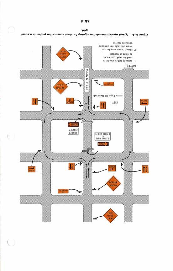
22 ROAD 1 CLOSED 1 where the road or street is open for traffic up to the point of closure. It shall carry the legend ROAD CLOSED (10) MILES AHEAD-LOCAL TRAFFIC ONLY or, optionally for urban use, STREET CLOSED TO THRU TRAFFIC and should be accompanied by appropriate detour signing (fig. 6-4, page 6B-6). The words BRIDGE OUT may be substituted for ROAD CLOSED where applicable. 10 MILES AHEAD LOCAL TRAFFIC ONLY /r r\ ROAD CLOSED TO THRU TRAFFIC 6B-10 Weight Limit Signs (R12-1, R12-2) For traffic safety in areas of road or street construction and maintenance, a Weight Limit sign shows the gross weight or axle weight that can be permitted on a roadway surface or bridge. Weight restrictions must be consistent with State or local regulations and shall not be imposed without the approval of the authority having jurisdiction over the highway. When weight restrictions are imposed, a marked detour should be provided for vehicles whose legal weight exceeds the limit posted. Rev. 3/86

23 TONS pi 5 TONS WEIGHT LIMIT a 8T A! 12T 16T 6B-11 Special Regulatory Signs Various other regulatory signs may be called for by special operations located in or around the roadway. Although it is not practicable to standardize many such signs in detail, they should conform to the general requirements pertaining to color and shape. Their messages should be brief, legible, and clearly understandable. Warning Signs 6B-12 Function Warning signs for construction and maintenance projects are used to notify drivers of specific hazards which may be encountered, when those operations are underway. Within the construction zone there may be a variety of temporary roadway facilities. Pavement width may be reduced. Open excavations may be present in or near the roadway, or travel across an unpaved section may be required. Drivers should be properly alerted to possible dangers ahead in sufficient time to adjust their speed for the hazard. - 6B-13 Design and Application Warning signs for construction and maintenance shall be diamond shaped (square with one diagonal vertical), having a black symbol or message on an orange background except as provided for herein. Construction or maintenance operations on freeway or expressway facilities, may also require large movable warning signs. Mounting considerations for some of these signs may justify a change from the standard diamond shape to a rectangular shape, but such variances should have prior approval of the appropriate highway authority. Rev. 3186
 shall have a black message and border, and shall have an orange background when used in 1 conjunction with an orange background sign and shall have a yellow background when used with a yellow")
24 The square Advisory Speed plate (sec. 6B-34) shall have a black message and border, and shall have an orange background when used in 1 conjunction with an orange background sign and shall have a yellow background when used with a yellow background sign. It shall have a minimum 24x24 inches size when used with a 36x36 inches sign or larger. Detailed specifications are given only for signs prescribed for construction and maintenance work and for some of the standard signs that are commonly required for these work areas. On secondary roads or city streets where speeds are low, the use of plates 6 inches smaller on a side than the standard size, but not less than 24 inches, may be used for warning signs having short word messages or clear symbols. Where distances are to be shown on warning signs as part of the legend, a separate panel with the distance shown thereon may be erected immediately below the sign on the same support. Where any part of the roadway is obstructed or closed, construction approach warning signs are required to alert traffic well in advance of these obstructions or restrictions to normal traffic flow (sec. 6B-14). These signs may be used singly or in combination. Because of their importance, these signs shall have a standard size of 48 inches by 48 inches and shall be the standard diamond shape for warning signs, except as provided for above. Where speeds and volumes are relatively low, a minimum size of 36 inches by 36 inches may be used for Construction Approach Warning Signs, provided that a minimum letter size of 5 inches can be accommodated on this size with the appropriate legend. 6B-14 Application of Construction Approach Warning Signs Various circumstances will occur which will require extra advance warning because of limited sight distance or the nature of the obstruction may require a motorist to bring his vehicle to a stop. Therefore, specified standards or a set sequence of signs are not noted. The determination of the sign or signs to be used shall be on the basis of an engineering study using the following sections as guidelines (sec. 6B-15 through 6B-20). As an alternate to the specific distances on these advance construction signs, the word AHEAD may be used. 6B-15 Advance Road (Street) Construction Sign (W20-1) The Advance Road (Street) Construction sign is to be located in advance of the initial activity or detour a driver may encounter, and is intended for use as a general warning of obstructions or restrictions. It carries the legend ROAD (STREET) CONSTRUCTION (1,500) FT or ROAD (STREET) CONSTRUCTION (%) MILE. It may be used in repetition with appropriate legends, or in conjunction with other construction signs. Rev. 3/86
25 , ' ROAD ' r- 6B-16 Advance Detour Sign (W20-2) The Advance Detour sign is intended for use in advance of a point at which traffic is diverted over a temporary roadway or route. It carries the legend DETOUR (1,500) FT or DETOUR (%) MILE. It may be used with repetition with appropriate legends or in conjunction with other construction signs. I i I I I 1 I 6B-17 Advanced Road (Street) Closed Sign (W20-3) The Advance Road (Street) Closed sign is intended for use in advance of a point at which a roadway is closed to all traffic or to all but local traffic. It carries the legend ROAD (STREET) CLOSED (1,000) FT or ROAD (STREET) CLOSED (%) MILE. It may be used in repetition with appropriate legends or in conjunction with other construction signs. 6B-19 Rev. 3186
 FT or ONE LANE ROAD (%) MILE. It may be used in repetition with appropriate legends or in conjunction with other construction signs.")
26 6B-18 Advance One Lane Road Sign (W20-4) The Advance One Lane Road sign is intended for use only in advance of a point where traffic in both directions must use a single lane (secs. 6F-6 and 7). It carries the legend ONE LANE ROAD (1,000) FT or ONE LANE ROAD (%) MILE. It may be used in repetition with appropriate legends or in conjunction with other construction signs. If the one-lane stretch is of such length as not to be visible throughout from either end, or if the traffic is of such volume that simultaneous arrivals at both ends occur frequently, provision must be made to permit traffic to move alternately under control (secs. 6F-6 to 6F-10). W x 36" Supplemental Plate 24 x 18" 1 6B-19 Advance Lane Closed Sign (W20-5) The Advance Lane Closed sign is intended for use where applicable in advance of a point where one lane of a multiple-lane roadway is closed (sec. 6G-3). It carries the legend RIGHT (LEFT) LANE CLOSED (1,000) FT or RIGHT (LEFT) LANE CLOSED (%) MILE. It may be used in repetition with appropriate legends or in conjunction with other construction signs. 6B-20 Advance Flagger Sign (W20-7) The Advance Flagger sign is intended for use in advance of any point at which a flagger has been stationed to control traffic through a construction or maintenance project. It carries the flagger symbol. When needed, an appropriate distance message may be displayed on a supplemental plate below the symbol sign. It may be used in repetition with appropriate revisions in the supplemental distances plate or in conjunction with other construction signs. The word message sign W20-7 with appropriate distances may be used as an alternate to the W20-7a flagger symbol sign. The sign shall be promplty removed, covered, or turned to face away from the roadway whenever the flagger is not at the station. Rev. 3186
27 6B-21 Two-Way Traffic Sign (W6-3) ) Two-Way Traffic sign should be used as needed at intervals to periodically remind drivers that they are on a two-way highway which contains opposing traffic. 6B-22 Application of Maintenance and Minor Construction Warning Signs At many maintenance and minor construction operations, particularly on lightly traveled roads, there may be no need for the sequence of Construction Approach Warning signs prescribed for major operations. The signs described in the following sections and on figures 6-13a and 6-13b, will ordinarily provide sufficient advance warning in such situations, either by themselves or in combination with appropriate Construction Approach Warning signs, as dictated by conditions. In addition, some of them may be needed inside the limits of a major work area where traffic is maintained through the job. 6B-23 Worker Sign (W21-1) A Worker sign is intended for use in conjunction with minor maintenance and public utility operations for the protection of workers in or near the roadway. On low-speed urban roads a Worker sign is intended for use at limited obstruction sites which are adequately marked and clearly visible, such as an open manhole with a fence around it. The W21-1 word message sign may be used as an alternate to the W21-la Worker Symbol sign. Rev. 3/86
28 M"" W8 2 M" 7 '""L,.'I, MERG ' '.EF1 r I Figure Warning signs used in comt~ction omas
29 ' 'YY k WIO-1 36" Diameter Figure Warning signs used in construction areas
30 6B-24 Fresh Oil Sign (W21-2) The FRESH OIL (TAR) sign is intended for use to warn motorists that resurfacing operations have rendered the surface of the pavement temporarily hazardous, and that objectionable splashing on vehicles may occur. 6B-25 Road Machinery Sign (W21-3) The ROAD MACHINERY sign is intended for useih areas where heavy equipment is operating in or adjacent to the roadway. 6B-26 Road Work Sign (W21-4) The ROAD WORK sign is intended for use in advance of maintenance or minor reconstruction operations in the roadway (fig. 6-9, page 6B-11). 6B-27 Shoulder Work Sign (W21-5) The SHOULDER WORK sign is intended for use in advance of maintenance or minor reconstruction operations involving the shoulder, where the traveled way remains unobstructed. Rev. 3/88
 energy can cause the premature firing of electric blasting caps used in construction operations, the public must be warned of such")
31 6B-28 Survey Crew Sign (W21-6) The SURVEY CREW sign is intended for use in advance of a point where a surveying crew is working in or adjacent to the roadway. 6B-29 Signs for Blasting Areas As sources of radio-frequency (RF) energy can cause the premature firing of electric blasting caps used in construction operations, the public must be warned of such conditions and, as a part of the overall safety precautions, be advised to turn off mobile radio transmitters. From a practical standpoint, however, the possibility of a premature explosion is extremely remote due to the necessary combination of circumstances that is very unlikely to occur in actual practice. There does not appear to be a radio-frequency (RF) initiation hazard in the normal storage and transportation of electric blasting caps as long as they are in their original cartons. The Institute of Makers of Explosives Publication No. 20, "Radio Frequency Energy, A Potential Hazard in the Use of Electric Blasting Caps," should be consulted for information on this hazard and guidelines for safe operations. This publication provides tables of recommended safe distances which will give the blaster a high degree of assurance that his blasting layout should be safe against radio frequency (RF) initiation. As a precautionary measure a sequence of signs is recommended for use to remind operators of mobile radio equipment to turn off transmitters when in a blasting area. The maximum power for amateur radio mobile units being 1,000 watts, a minimum safe distance of 1,000 feet is recommended for warning sign placement to satisfy the worst condition. Occasionally, situations may develop where adherence to the 1,000 foot distance or to the tables in Publication No. 20 will create an operational handicap. In these instances it is recommended that competent experts be consulted to evaluate the particular situation. Recommended practices for warning sign application follow. I Radio Frequency Energy, "A Potential Hazard in the Use of Electric Blasting Caps," Publication No. 20, Institute of Makers of Explosives, 420 Lexington Avenue, New York, New York Rev. 3/86

32 6B-30 Blasting Zone Sign (W22-1) The BLASTING ZONE (1,000) FT sign is intended for use in advance 3 of any point or work site where there are explosives being used. The TURN OFF 2-WAY RADIO and END BLASTING ZONE signs must be used in sequence with this sign. Provision shall be made for covering or removing the sign sequence when there are no explosives in the area or the area is otherwise secured. TURN OFF 2 -WAY RADIO END BLASTlNl ZONE 6B-31 Turn Off 2-Way Radio Sign (W22-2) The TURN OFF 2-WAY RADIO sign is to be used in sequence with the BLASTING ZONE (1,000) FT and END BLASTING ZONE sign and placed at least 1,000 feet from the beginning of the blasting zone. These signs shall be prominently displayed and covered or removed when there are no explosives in the area or the area is otherwise secured. 6B-32 End Blasting Zone Sign (W22-3) The END BLASTING ZONE sign is to be used to denote the end of the danger zone and shall be placed a minimum of 1,000 feet from the blasting zone, either with or preceding the END CONSTRUCTION sign Other Warning Signs In addition to the warning signs specifically related to construction and maintenance operations there are numerous other warning signs, standardized for general use and treated in Part I1 of this Manual, that may find application in work areas. These include the following: 1. Large Arrow (Wl-6) 2. ROAD NARROWS (W5-1) 3. Divided Highway Ends (W6-2) 4. BUMP (W8-1) 5. DIP (W8-2) 6. Pavement Ends (W8-3) 7. SOFT SHOULDER (8-4) Rev. 3/86
33 8. TRUCK CROSSING (W8-6) 9. LOOSE GRAVEL (W8-7) lo. ROUGH ROAD (8-8) 11. Low Shoulder (W8-9) 12. BE PREPARED TO STOP 13. Chevron Panels. The application of most of these signs is prescribed in detail in Part I1 of this Manual, although their application is generally apparent from their legends. When used in construction operations, these signs shall have an orange background and when used in highway maintenance operations, they should have an orange background. VI-4 (c) Rev Advisory Speed Plate (W13-1) In conjunction with a warning sign, an Advisory Speed plate may be used to indicate a maximum recommended speed through the hazardous area. For use with orange construction and maintenance signs this plate shall have a black legend on an orange background and when used with yellow background warning signs shall have a yellow background. Except in emergencies, an Advisory Speed plate shall not be erected until the recommended speed has been determined by the authority in charge of the highway. Guide Signs 6B-35 Function and Design of Information and Guide Signs The following informational signs are required at construction and maintenance sites: 1. Standard route markings, to the extent that temporary route changes are necessary. 2. Directional signs and street name signs, when used in conjunction with detour routing may have a black legend on an orange background. Rev. 3186
 The Length of Construction sign shall be erected at the limits of any road construction or maintenance job of more than 2 miles in extent, where traffic is")
34 3. Special information signs (secs. 6B-36 to 39) relating to the work being done. These signs shall have a black message on an orange background. 6B-36 Length of Construction Sign (G20-1) The Length of Construction sign shall be erected at the limits of any road construction or maintenance job of more than 2 miles in extent, where traffic is maintained through the job. It carries the legend ROAD CONSTRUCTION NEXT (5) MILES. It can be effectively mounted on a wing barricade. This sign may be used where required, for jobs of lesser length or on urban streets with appropriate distances shown. NEXT 5 MILES - CONSTRUCTION 6B-37 End Construction (Road Work) Sign (G20-2) The END CONSTRUCTION (ROAD WORK) sign should be erected approximately 500 feet beyond the end of a construction or maintenance job. It may be erected on the back of a warning sign set up facing the opposite direction of traffic or on the back of a wing barricade. Where appropriate, the legend END ROAD WORK may be used. 6B-38 Detour Signs and Markers (M4-8, 9, and 10) The Detour Arrow sign (4-10) is used at a point where a detour roadway or route has been established due to the closure of a street or highway to through traffic. It should normally be mounted just below the ROAD CLOSED sign (sec. 6B-8) or the Local Traffic Only sign (sec. 6B-9). The Detour Arrow sign uses a horizontal arrow pointed to the right or left as required at each location. Each detour shall be adequately marked with standard temporary route markers and destination signs as a responsibility of the highway agency. The Detour marker (M4-8) (sec. 2D-24) mounted at the top of a route marker assembly is to be used to mark a temporary route that branches from a regular numbered route, bypasses a section of a route which is closed or Rev. 3186
 is to be used for unnumbered routes; for use in emergency situations; for periods of short durations; or where, over relatively short distances, it is not necessary to show route markers to")
35 m l DETOUR blocked by construction, major maintenance, roadway damage or traffic emergency and rejoins the regularly numbered route beyond that section. The Detour sign (M4-9) (sec. 2D-25) is to be used for unnumbered routes; for use in emergency situations; for periods of short durations; or where, over relatively short distances, it is not necessary to show route markers to guide traffic along the detour and back to its desired route. A Street Name sign may be placed above or incorporated in the Detour sign (M4-9) to indicate the name of the roadway for which the detour was established. The End Detour sign (M4-8a or M4-8b) may be used to advise the, motorist that the detour has ended. The End Detour sign may be used on either numbered highways or unnumbered roadways. If used on a numbered highway, it should be erected above a route marker located near the end of the detour. Iv-15 (C, Rev. 2 (=, Rev.2 6B-39 Pilot Car Sign (G20-4) The Pilot Car sign shall be mounted in a conspicuous position on the rear of a vehicle used for guiding one-way traffic through or around a road construction or maintenance project (sec. 6F-9). It carries the legend PILOT CAR-FOLLOW ME. A flagger must be stationed on every approach to a project on which a pilot car is used, to hold traffic as necessary until the pilot car is available to lead.. 'OLLOW MI. Rev. 3/66
36

37 C. BARRICADES AND CHANNELIZING DEVICES 6C-1 Function The function of channelizing devices are to warn and alert drivers of hazards created by construction or maintenance activities in or near the traveled way, and to guide and direct drivers safely past the hazards. Channelizing devices as used herein includes but is not limited to cones, vertical panels, drums, barricades, and barriers. Devices used for channelization should provide a smooth and gradual transition in moving traffic from one lane to another, onto a bypass or detour, or in reducing the width of the traveled way. They should be constructed so as not to inflict any undue damage to a vehicle that inadvertently strikes them. The objective should be the development of a traffic control plan which uses a variety of traffic control measures and devices in whatever combination necessary to assure smooth, safe vehicular movement past the work area and at the same time provide safety for the equipment and the worker on the job. Channelizing devices are elements in a total system of traffic control devices for use in highway construction and maintenance operations. These elements shall be preceded by a subsystem of warning devices that are adequate in size, number, and placement for the type of highway on which the work is to take place. Typical application of channelizing devices are shown in Figure 6-2 to VI-30(c) Rev. 4 6C-2 Channelization The single most important element, within the system of traffic control devices commonly used in construction or maintenance areas (where a reduction in pavement width is involved), is the taper that is provided for the channelization. An inadequate taper will almost always produce undesirable traffic operations with resulting congestion and possibly accidents through the area. The minimum desirable taper length for construction and maintenance purposes should be computed by the formula L = S x W, for all freeways, expressways, and other roadways having a posted speed of 45 mph or greater. The formula L = WS2/60 should be used to compute taper length on urban, residential and other streets where the posted speeds are 40 mph or less. Under either formula, L equals the taper length in feet, W the width of offset in feet, and S the posted speed or off-peak 85 percentile speed. The minimum desirable length derived from the appropriate formula above applies to roadway conditions of relatively flat grades and straight Rev. 3186

38 alignment. Adjustments may become necessary to provide adequate sight distance on the approach to the channelization. Similarly, the proximity of interchange ramps, crossroads, etc., to the work site may dictate the need for adjustments. In general, better traffic operations will result when the adjustments consist of increasing the length of the taper rather than reducing the length (below the minimum desirable recommended above). The real test concerning adequate length of taper is the operation of vehicles through the transition. It should be long enough so that drivers of vehicles approaching side by side have sufficient length in which to adjust their respective speeds and merge into a single lane before the end of the transition. A brief period of observing driver performances will generally provide some clear indications of the adequacy of the taper length. For example, if severe brake applications are observed, an increased taper length is indicated. The maximum spacing between devices in a taper should be approximately equal in feet to the speed limit. For example, if the taper is on a roadway with an existing 55 MPH speed limit, the devices should be spaced about 55 feet. Devices placed on a tangent to keep traffic out of the closed lane should be spaced in accordance with the extent and type of activity, the speed limit of the roadway, and the vertical and horizontal alignment of the roadway such that it is apparent the roadway is closed to traffic. On construction projects, channelization often remains in the same place for long periods of time. During such a long interval some of the elements-cones, barricades, barrels, etc.-get out of their original alignment due to being struck, moved due to construction activities, etc. It is necessary, therefore, to patrol the channelization at regular intervals to assure its proper functioning as a traffic control device. Replacement or shifting of the elements into the original alignment can best be done if the original positions of the elements had been indicated on the pavement by paint marks. This technique assures good alignment and proper vehicle performances over a long period of time with minimum expenditure of men and materials in maintaining the channelization. Sometimes during maintenance operations, work at one site will extend over several days, thereby requiring that channelization be set up each morning and removed each evening. Under these circumstances the locations of the cones, barrels, etc., should be marked at the time of the original set-up to facilitate the rapid, orderly re-setting of the devices on each succeeding day. 6C-3 Cone Design Traffic cones and tubular markers of various configurations are available. These shall be a minimum of 18 inches in height with a broadened base and may be made of various materials to withstand impact Rev. 3/86

39 without damage to themselves or to vehicles. Twenty-eight inches should be the minimum height of cones used on freeways and other high-speed roadways and on all facilities during hours of darkness or whenever more conspicuous guidance is needed. Orange shall be the predominant color on cones. They should be kept clean and bright for maximum target value. For nighttime use they shall be reflectorized or equipped with lighting devices for maximum visibility. Reflectorized material shall have a smooth, sealed outer surface which will display the same approximate color day and night. Reflectorization of tubular markers shall be a minimum of two threeinch white bands placed a maximum of 2" from the top with a maximum of 6" between the bands. Reflectorization of cones shall be provided by a minimum 6" white band placed a maximum of 3" from the top. VI-zqc) Rev. 4 g:;1z2(c) 6C-4 Cone Application Included under this heading are a group of devices whose primary function is the channelization of traffic. They may be conical in shape, but there are also tubular shaped devices available capable of performing the same function. They may be set on the surface of the roadway or rigidly attached for continued use. Traffic cones may be easily stacked on a truck and one worker can carry and distribute several cones with ease. This mobility and flexibility (which cannot be equalled by Type I barricades) increases the usefulness of these devices. When cones are used, precautions are necessary to assure they will not be blown over or displaced. This may be particularly critical adjacent to lanes of moving traffic where there may be a wind created by passing vehicles. Some cones are constructed with bases that may be filled with ballast. With others it may be necessary to double the cones or use heavier weighted cones, special weighted bases, or weights such as sand bag rings that can be dropped over the cones and onto the base to provide increased stability. These added weights should not be sufficient to present a hazard if the devices are inadvertently struck. In general, traffic cones have a greater target value than do the tubular shaped devices. However, the target value of either device may be enhanced during the day time by the insertion of an orange flag in the top and at night, by reflectorization or the use of lighting devices. 6C-5 Vertical Panel-Design and Application Vertical panels used as channelizing or warning devices shall be 8 to 12 inches in width and a minimum of 24 inches in height. They shall be orange and white striped and reflectorized in the same manner as barricades and mounted with the top a minimum of 36 inches above the roadway. For panels less than 3 ' in height, 4"stripes shall be used. If used Rev. 3/66
.")
40 for traffic in two directions, back to back panels shall be used. These devices may be used for traffic separation or shoulder barricading where 1 space is at a minimum. Panels with stripes which begin at the upper right side and slope downward to the lower left side are to be designated as 'right' panels (VP-1R). Panels with stripes which begin at the upper left side and slope downward to the lower right side are to be designated as 'left' panels (VP-1L). For nighttime use, it is desirable to place flashing warning lights on vertical panels when they are used singly and steady burn warning lights on vertical panels when they are used in a series for channelization. 6C-6 Drum Design Drums used for traffic warning or channelization shall be approximately 36 ' in height and a minimum of 18 " in diameter. The markings on drums shall be horizontal, circumferential, orange and white reflectorized stripes four to eight inches wide, using a material that has a smooth, sealed outer surface which will display the same approximate size, shape and color day and night. There shall be at least two orange and two white stripes on each drum. If there are nonreflectorized spaces between the horizontal orange and white stripes, they shall be no more than two inches wide. 6C-7 Drum Application Drums are most commonly used to channelize or delineate traffic flow but may also be used singly or in groups to mark specific hazards. Drums are highly visible and have good target value, give the appearance of being formidable obstacles and, therefore, command the respect of drivers. They are portable enough to be shifted from place to place within a construction project in order to accommodate changing conditions but are generally used in situations where they will remain in place for a prolonged period of time. When drums are placed in the roadway, appropriate advance warning signs shall be used. Drums should not be weighted with sand, water, or any material to the extent that would make them hazardous to motorists. When they are used in regions susceptible to freezing, they should have drain holes in the bottom so water will not accumulate and freeze causing a hazard if struck by a motorist. During hours of darkness a flashing warning light should be placed on drums used singly and steady-burn warning lights should be placed on drums used in a series for traffic channelization. Small arrow signs or vertical panels mounted above drums may be used as supplements to drum delineation. Rev. 3186

41 , 6G8 Barricade Design A barricade is a portable or fixed device having from one to three rails with appropriate markings used to control traffic by closing, restricting, or delineating all or a portion of the right-of-way. Barricades shall be one of three types: Type I, Type 11, or Type 111. The characteristics of these types are shown in Figure 6-14 and Table VI-1. Barricades with stripes which begin at the upper right side and slope downward to the lower left side are to be designated as 'right' (R) barricades. Barricades with stripes which begin at the upper left side and slope downward to the lower right side are to be designated as 'left' (L) barricades. Markings for barricade rails shall be alternate orange and white stripes (sloping downward at an angle of 45 degrees in the direction traffic is to pass). Where a barricade extends entirely across a roadway, it is desirable that the stripes slope downward in the direction toward which traffic must turn in detouring. Where both right and left turns are provided for, the chevron striping may slope downward in both directions from the center of the barricade. Barricade rails should be supported in a manner that will allow them to be seen by the motorist and provide a stable support not easily blown over by the wind or traffic. For Type I barricades, the support may include other unstriped horizontal panels necessary to provide stability. To facilitate rapid identification of channelizing devices on a job site, the name and phone number only of an agency, contractor, or supplier may be shown on the nonreflective surface of the face part of a barricade. Such identification shall be in one color and nonreflective with letters not to Table VI-1 Barricade Characteristics Type* vi-28(c) R,V. 4 exceed.l-inch in height. The entire area of orange and white shall be reflectorized with a material that has a smooth, sealed outer surface which will display the same VI-~~(C) approximate size, shape and color day and night. I Rev. 4 Width of Rail 8" min-12" max 8" min-12" max 8" min-12" max Length of Rail 2 ft. min 2 ft. min 4 ft. min Width of Stripes** 6 in. 6 in. 6 in. Height 3 ft. min 3 ft. min 5 ft. min. Number of 2 (one each 4 (two each 3 if facing traffic Reflectorized direction) direction) in one direction - Rail Faces 6 if facing traffic in two directions Ib * For wooden barricades nominal lumber dimensions will be satisfactory ** For rails less than 3 feet long, 4 inch wide stripes shall be used Rev. 3186
42 WARNING LIGHT IOotionall WARNING LIGHT 18" MINIMUM TYPE I BARRICADE DRUM TYPE IIBARRICADE - VERTICAL PANEL TYPE III BARRICADE 4, BASE VARIES CONES Note: Flashing or rteady burn warning lights should be used on barricades, panels, and drums as needed. HIGH LEVEL WARNING DEVICE Figure Channelizing devices and high level warning devices. 6C-6

43 Barricades are located adjacent to traffic and therefore subject to ) impact by errant vehicles. Because of their vulnerable position and the possible hazard they could create, they should be constructed of lightweight materials and have no rigid stay bracing for "A" frame designs. 6C-9 Barricade Application Type I or Type I1 barricades are intended for use in situations where traffic is maintained through the area being constructed and/or reconstructed. They may be used singly or in groups to mark a specific hazard or they may be used in a series for channelizing traffic. Type I barricades would normally be used on conventional roads or urban streets and arterials. As Type I1 barricades have more reflective area, they are intended for use on expressways and freeways or other high speed roadways. On high speed expressways or in other situations where barricades may be susceptible to overturning in the wind, sandbags should be used for ballasting. Sandbags may be placed on lower parts of the frame or stays to provide the required ballast but shall not be placed on top of any striped rail. Where maintenance activities are being performed, a street or highway condition is seldom of a character that will require a complete closing of the facility. When such a condition does occur, it is almost always an emergency situation, as would result from a broken water main or a washed-out culvert, for example. Repair work is generally initiated on an emergency basis and the street or road closing generally is of a kind wherein Type I is used. On construction projects, when a road section is closed to traffic, Type 111 barricades shall be erected at the points of closure. They may extend completely across a roadway and its shoulders or from curb to curb. Where provision must be made for access of equipment and authorized vehicles, the Type I11 barricades should be provided with gates or movable sections that can be closed when work is not in progress, or with indirect openings that will discourage public entry. Where access is provided through the Type I11 barricades, responsibility should be assigned to a person to assure proper closure at the end of each working day. When a road or street is legally closed, but access must still be allowed for local traffic, the Type 111 barricade cannot be erected completely across a roadway. Instead, an arrangement should be devised that will permit local use but effectively discourage use by through traffic. A sign with the appropriate legend concerning permissible use by local traffic shall be installed. Applications of this principle are illustrated in figures 6-3 and 6-4 (pages 6B-5 and 6B-6). Wing barricades are a special application of Type 111 barricades, erected on the roadway shoulder (on one or both sides of the pavement) to give the Rev. 3/86

44 illusion of a narrowed or restricted roadway. In advance of a construction or maintenance area, even where no part of the roadway is actually closed, 1 wing barricades serve a useful purpose in alerting the driver. If used in a series, they should start at the outer edge of the shoulder and be brought progressively closer to the pavement. Wing barricades may be used as a mounting for the advance warning or guide signs or lighting devices. During periods of inactivity, a foldaway type of design may be advantageous. Examples of wing barricades are shown in figure Signs may be erected on barricades, particularly those of the fixed type, and they offer a most advantageous facility for this purpose. The ROAD CLOSED and Detour Arrow signs, and the Large Arrow warning signs, for example, can effectively be mounted on or above the barricade that closes the roadway. Construction and maintenance zones often encroach into sidewalks or crosswalks necessitating provisions for alternate routing. Where it is not possible to close a path and divert the pedestrians to other walkways, barricades may be used to define the path. Flashers should be used on sidewalk barricades in accordance with the following paragraph however, where high levels of illumination exist.for sidewalk areas the use of flashers on barricades may not be needed. For nighttime use, it is desirable to add flashing warning lights when barricades are used singly and steady burn lights when barricades are used \ in a series for channelization. 6C-10 Portable Barrier-Design and Application Barriers are highway appurtenances designed to prevent vehicular penetration from the travelway to areas behind the barrier such as to minimize damage to impacting vehicles and their occupants. They may also be used to separate two-way traffic. Portable barriers are barriers that are capable of being moved from one site to another. These devices may be constructed of concrete, metal, or any material that will act to physically deter access of vehicles from certain portions of the right-of-way. Barriers may serve an additional function of channelizing traffic; however, their use should be determined by engineering analysis and the protective requirements of the location, not the channelizing needs. When serving the additional function of channelizing traffic, portable barriers should be of a light color for increased visibility. For nighttime use, barriers shall be supplemented by the use of standard delineation or channelization markings or devices. Barricade warning lights may be installed on continuous barriers. On each side of the roadway only the first two yellow warning lights at the start of a continuous barrier may be Type A flashing. Subsequent warning lights on the barrier shall be Type C yellow steady-burning for channelization. Rev. 3/86
45 The effect of impacting the ends of barriers should be mitigated. Such ) mitigating measures include the use of crash cushions or flaring the ends of barriers away from the travelway. 6C-11 High Level Warning Device-Design and Application High level warning devices are used to supplement other controls and devices necessary to alert motorists of construction and maintenance activities or obstructions in the roadway and are designed so as to be seen over the top of preceding vehicles. They shall consist of a minimum of three flags with or without a Type B High Intensity Flashing Warning Light. The distance from the roadway to the bottom of the lens of the light and/or the lowest point of all three flags shall be no less than 8 feet. The flags shall be 16 inches square or larger and shall be orange or fluorescent red-orange in color. High level warning devices are most commonly used in urban high density traffic situations to warn motorists of operations such as pavement patching, manhole work, surveying, utility work, etc. Rev. 3/66
46

47 D. MARKINGS 6D-1 Pavement Markings Applications When construction work necessitates the utilization of vehicle paths other than the lanes normally used, daytime and nighttime drive-through checks should be made to evaluate the path and the possibility that the pavement markings might inadvertently lead drivers from the intended path. Markings no longer applicable which might create confusion in the minds of vehicle operators shall be removed or obliterated as soon as practicable. Ideally, inappropriate existing pavement markings should be removed and the new delineation placed before opening the affected lane or lanes to traffic. Traffic shifts from one path to another should not be attempted unless there is sufficient time, equipment, materials and personnel available to properly complete it before the end of the workday. Conflicting pavement markings must be obliterated to prevent confusion to vehicle operators. Proper pavement marking obliteration leaves a minimum of pavement scars and completely removes old pavement paint. Painting over existing stripes is not considered to meet the, requirements for removal or obliteration. The intended vehicle path should be clearly defined during day, night, and twilight periods under both wet and dry pavement conditions. Where stage construction requires changes in barricades or channelization, similar day-night checks and evaluations of the existing pavement marking should accompany each change. When temporary roadway is constructed to bypass a closed portion of highway, appropriate reflectorized pavement markings shall be placed on the approach to, and throughout the length of hard-surfaced temporary roadways. At locations where the duration of the temporary roadway is relatively short, pavement markings consisting of reflectorized paint lines may not be practical due to the time required and expense involved in their removal. Under the above conditions, adequate short-term expendable pavement markings can be provided by use of pressure sensitive traffic marking tape or raised pavement markers. Either of these types of devices can be applied simply and quickly and can be removed with little or no difficulty when changing traffic patterns make the installation obsolete. Temporary pavement markings shall be used in combination with appropriate warning signs, channelizing devices and delineation to clearly indicate the required vehicle paths. Where maintenance activities are being performed, the use of pavement markings generally has little application. Normal maintenance work is considered to be that type of work which would be accomplished within Rev. 3186
48 one or more continuous workshifts with the worksite being protected by an adequate complement of warning signs, flagger and channelizing devices to indicate the proper vehicle path. Longer term maintenance work should, for the purpose of traffic handling through the worksite, be treated as a "construction" project. 6D-2 Delineators Delineation in construction and maintenance zones is intended to be a guide to indicate the alignment of the roadway and outlines the required vehicle path through these areas. Delineators are not to be used as a warning device. Delineators are reflector units capable of clearly reflecting light under normal atmospheric condition from a distance of 1000 feet when illuminated by the upper beam of standard automobile lights. Reflective elements for delineators shall have a minimum dimension of approximately 3 inches. Delineator applications in construction or maintenance areas, should always be made in combination with some of the other traffic control devices discussed in Part VI-C. Delineators, when used, shall be mounted on suitable supports so that the reflecting unit is about 4 feet above the near roadway edge. The standard color for delineators used along the right side of streets and highways shall be white. The color of delineators used along the left edge of divided streets and highways and one-way roadways shall be yellow. Spacing along roadway curves should be such that several delineators are always visible to the driver. Rev. 3/86

49 E. Lighting Devices 6E-1 Function Construction and maintenance activities often create conditions on or near the traveled way that are particularly hazardous at night when drivers' visibility is sharply reduced. It is often desirable and necessary to supplement the reflectorized signs, barriers and channelizing devices with lighting devices that are described in the following paragraphs. Three types of electric lights are commonly used: floodlights, steadyburning lights, and flashing lights. 6E-2 Floodlights On construction projects, floodlights have a limited, but important application. Sometimes large construction contracts are prosecuted on a double shift basis, particularly earth moving activities. Oftentimes, the earth moving involves a haul road crossing a public highway, at which point a flagger station is generally set up. In order to assure the safest possible conditions at this type of location, it is advisable to supplement the warning devices (used in advance of the crossing) with floodlighting of the flagger station and the crossing site. Care is required in order to adequately illuminate the desired area without creating glare in the eyes of drivers on the highway. The adequacy of the floodlight placement can best be determined by driving through and observing the floodlighted area from each direction on the highway. Maintenance activities on urban freeways, with high volume, high density traffic conditions, are frequently required to be conducted during nighttime periods (with low traffic volumes). Good floodlighting of the work site is a necessity because the workers need to see what they are doing and because the workers and the worksite need to be seen by passing drivers. The lighting units should be positioned so they do not cause glare to drivers on the highway. 6E-3 Hazard Identification Beacons (Flashing Electric Lights) A Hazard Identification Beacon is a flashing yellow signal light (minimum diameter 8 inches) used at points of special hazard as a means of calling drivers' attention to these locations. When used, the flashing beacon should operate 24 hours a day. On construction projects, because of the time and effort required to install and put these units into operation, they are used, generally, only at locations where frequent changes would not be required. Rev. 3/86

50 On projects where an existing dual highway is being upgraded to freeway standards (which requires the use of crossovers to permit stage construction) flashing beacons have been used effectively to call drivers' attention to the hazard created by the necessary channelizing devices. Similarly, the temporary terminus of a freeway (where all traffic is channelized into an exit) is a location where beacons have informed drivers of the speed reduction necessary in transitioning from freeway to local road operations. Hazard Identification Beacons may be rated singly or in groups containing more than one unit. During normal daytime maintenance operations, the functions of flashing beacons are adequately provided for by the lighting equipment on maintenance vehicles, either the emergency flashers, the rotating dome light, or both. However, at locations where the daytime maintenance activity requires an obstruction to remain in the roadway at night, flashing beacons may be installed at the point of hazard. At locations where vandalism is no problem, the power may be provided by a portable electric generator. (See sec. 4E-5) 63-4 Steady-Burning Electric Lamps As used herein, steady-burning electric lamps shall mean a series of low wattage yellow electric lamps. They may be used to mark obstructions or hazards, but they are generally less effective than flashing lights for these uses because of the attention getting effect of the latter. However, where lights are needed to delineate the traveled way through and around obstructions in a construction or maintenance area, the delineation shall be accomplished by use of steady-burning lamps. Steady-burning lamps, placed in a line on longitudinal barricades, have been effective in delineating the proper vehicle path through stage construction areas (which require changing patterns of traffic movement). The application of these devices during maintenance activities is infrequent due to the generally short time nature of maintenance work. A type of maintenance activity where steady-burning lamps could be utilized is the removal and replacement of a portion of a bridge deck. The lamps could be mounted on barricades and effectively aid in channelizing traffic around the work area. 6E-5 Warning Lights As used herein, Warning Lights are portable, lens directed, enclosed lights. The color of the light emitted shall be yellow. They may be used in either a steady-burn or flashing mode. Warning lights shall be in accordance with the current ITE Purchase Specifications for Flashing and Steady-Burn Warning Lights. VI-18 (c) Rev. 3 Rev. 3/86

51 Type A Low Intensity Flashing Warning lights are most commonly ) mounted on barricades, drums, vertical panels or advance warning signs and are intended to continually warn drivers that they are approaching or proceeding in a hazardous area. Warning lights shall have a minimum mounting height of 36 inches to the bottom of the lens. Type B High Intensity Flashing Warning lights are normally mounted on the advance warning signs or on independent supports. Extremely hazardous site conditions within the construction area may require that the lights are effective in daylight as well as dark, they are designed to operate 24 hours per day. Type C Steady-Burn lights are intended to be used to delineate the edge of the traveled way on detour curves, on lane changes, on lane closures and on other similar conditions. Their application shall be as indicated in section 6E-4. The light weight and portability of warning lights are advantages that make these devices useful as supplements to the reflectorization on hazard warning devices. The flashing lights are effective in attracting a driver's attention and, therefore, provide an excellent means of identifying the hazard. Flashers shall not be used for delineation, as a series of flashers would tend to obscure the desired vehicle path. Warning lights on barricades shall be installed to a minimum mounting height of 36 inches to the bottom of the lens. Type A Low Intensity Flashing Warning Lights and Type C Steady Burn Warning Lights shall be maintained so as to be capable of being visible on a clear night from a distance of 3,000 feet. Type B High Intensity Flashing Warning Lights shall be maintained so as to be capable of being visible on a sunny day when viewed without the sun directly on or behind the device from a distance of 1,000 feet. Rev. 3 6E-6 Special Lighting Units Special lighting units, generally trailer-mounted for easy transport to a jobsite, have been developed to supplement conventional signs, pavement markings and lighting for maintenance activities. The flashing lights on the unit are operated from a self-contained power source mounted on the trailer, either batteries or an electric generator. A variety of light configurations are used for traffic warning and guidance. Most units are designed with racks, channels or other devices so that signs may be displayed with messages appropriate to the particular kind of work being performed. These special lighting units are used most frequently on high density urban freeways and are placed just in advance of the worksite. The flashing lights, together with appropriate signs, have proven to be very effective warning devices while also providing some physical protection to the maintenance workers. Rev. 3186

52 Although these special lighting units were developed to satisfy a need on urban freeways, they have many applications on all types of highways. Their mobility, together with the availability of flashing lights and/or a variety of sign messages makes them useful for almost any situation where conditions require extraordinary advance warning of the maintenance activities. If the units are to be used at night, consideration should be given to providing a means whereby the intensity of the flashers may be reduced during darkness when the lower intensities are desirable. 6E-7 Advance Warning Arrow Panel Advance warning arrow panels are sign panels with a matrix of lights capable of either flashing or sequential displays. Advance Warning Arrow panels.are intended to supplement other traffic control devices. Arrow panels will not solve difficult traffic problems by themselves, but they can be very effective when properly used to reinforce signs, barricades, cones, and other traffic control devices. Necessary signs, barricades, or other traffic control devices shall be used in conjunction with the advance warning arrow panel. Arrow panels are effective in encouraging drivers to leave the closed lane sooner. Arrow panels provide additional advance warning and directional information where traffic must be shifted laterally along the roadway. They assist in diverting and controlling traffic around construction or maintenance activities being conducted on or adjacent to the traveled way and give drivers positive guidance about a roadway path diversion that they might not otherwise expect. Arrow panels are generally used for day or night lane closures, roadway diversions, and slow-moving maintenance and construction activities on the traveled way. They are particulary effective under high-speed and high-density traffic conditions. At night, they are effective where other traffic control devices cannot provide adequate advance warning of a roadway path diversion. During daylight, arrow panels are effective under high-density traffic conditions that might block the driver's advanced view of construction or maintenance activities ahead. VI-I a(c) Rev. 2 6E-8 Advance Warning Arrow Panel Application Placement of arrow panel should be varied as needed to achieve the desired recognition distances. Also, care must be taken in the placement to avoid driver confusion in the vicinity of ramps, median crossovers, and side road intersections. For stationary lane closures, the arrow panel should be placed on the shoulder at the beginning of the taper, or where there are narrow shoulders, in the closed lane behind the channelizing devices on the same side of the lane closure. Placement at the start of the taper is preferred to placement in the middle of the taper. Rev. 3186

53 In diversions where arrow panel need has been determined, the arrow ) panel should be placed behind the barricades closing the roadway. For moving-maintenance activities where a lane is closed, it is preferable that the arrow panel be placed at the rear of the activity in the closed lane on a vehicle separate from the maintenance vehicle itself. The arrow panel should always remain upstream of the maintenance vehicle where adequate recognition distance is available. The vehicle carrying the arrow panel should also be equipped with appropriate signing and/or lighting. Generally arrow panels should not be used for shoulder or roadside work activities nor should they be used on two lane highways because the panels can cause unnecessary lane changing. 6E-9 Advance Warning Arrow Panel Specifications Advance warning arrow panel shall meet the specifications of Table VI-3. The minimum legibility distance for various traffic conditions are based on the decision-sight distance concept. Minimum legibility distances are those at which the arrow panel message can be comprehended by a driver on a sunny day or clear night. Also shown are the arrow panel sizes needed to meet the legibility distance needs. VI- 13(c) Rev. 2 Table VI-3 Advance Warning Arrow Panels Minimum Number Minimum Legibility Type Minimum Size of Panel Lamps Distance A 24" x 48" 12 Yz mile B 30" x 60" mile C 48" x 96" 15 1 mile Type A advance warning arrow panels are appropriate for use on low speed urban streets. Type B are appropriate for intermediate speed facilities and for maintenance or moving operations on high-speed roadways. Type C arrow panels are intended to be used on high-speed, high-volume construction projects. Arrow panels shall be rectangular, of solid construction, and finished with nonreflective flat black. The panels shall be mounted on vehicle, trailer, or other suitable support. Vehicle-mounted panels should be provided with remote controls. Minimum mounting height should be 7 feet above roadway to the bottom of the panel, except on vehicle mounted panels which should be as high as practicable. Arrow panels should have the capability of the following mode selections: (1) left or right flashing or sequential arrows; or (2) left or right sequential chevrons; and (3) double flashing arrows; and (4) caution. The caution mode consists of four or more lamps, arranged in a pattern which will not indicate a direction. VI-37 (i) Editorial Change Rev. 4 Rev. 3/86
54 Arrow panels shall be capable of a minimum of 50 percent dimming from their rated lamp voltage. The flashing rate of the lamps shall not be less than 25 nor more than 40 flashers per minute. Minimum lamp "on time" shall be 50 percent for the flashing arrow and 25 percent for the sequential chevron. The arrow panel lamps or lenses shall be recess mounted or, alternately equipped with an upper hood of not less than 180, and the color of the light emitted shall be yellow. VI- 13(c) Rev. 2 Rev. 3186

55 F. CONTROL OF TRAFFIC THROUGH WORKAREAS 6F-1 Function The primary function of traffic control procedures is to move traffic safely and expeditiously through or around workareas. The control of traffic through workareas is an essential part of highway construction and maintenance operations. For these operations there must be adequate legislative authority for the implementation and enforcement of needed traffic regulations, parking controls and speed zoning. Such statutes must provide sufficient flexibility in the application of traffic control to meet the needs of the changing conditions in workareas. Maintaining good public relations is necessary. The cooperation of the various news media in publicizing the existence of and reasons for worksites, therefore can be of great assistance in keeping the motoring public well informed. 6F-2 Hand Signaling Devices A number of hand signaling devices, such as STOP/SLOW paddles, lights and red flags are used in controlling traffic through work zones. The sign paddle bearing the clear messages STOP or SLOW provide motorists with more positive guidance than flags and should be the primary handsignaling device. Flag use should be limited to emergency situations and at spot locations which can best be controlled by a single flagger. Sign paddles should be at least 18 inches wide with letters at least 6 inches high. A rigid handle should be provided. This combination sign may be fabricated from sheet metal or other light semirigid material. The background of the STOP face shall be red with white letters and border. The background of the SLOW shall be orange with black letters and border. When used at night the STOP face shall be reflectorized red with white reflectorized letters and border, and the SLOW face shall be reflectorized orange and black letters and border. Flags used for signaling purposes shall be a minimum of 24 by 24 inches in size, made of good grade of red material securely fastened to a staff approximately 3 feet in length. The free edge should be weighted to insure that the flag will hang vertically, even in heavy winds. IV-20(c) Rev. 4 6F-3 Flaggers Since flaggers are responsible for human safety and make the greatest number of public contacts of all construction personnel, it is important Rev. 3/86

56 that qualified personnel be selected. A flagger should possess the following minimum qualifications: 1. Average intelligence. 2. Good physical condition, including sight and hearing. 3. Mental alertness. 4. Courteous but firm manner. 5. Neat appearance. 6. Sense of responsibility for safety of public and crew. The use of orange clothing such as a vest, shirt, or jacket shall be required for flaggers. For nighttime conditions similar outside garments shall be reflectorized. Flaggers are provided at worksites to stop traffic intermittently as necessitated by work progress or to maintain continuous traffic past a worksite at reduced speeds to help protect the work crew. For both of these functions the flagger must, at all times, be clearly visible to approaching traffic for a distance sufficient to permit proper response by the motorist to the flagging instructions, and to permit traffic to reduce speed before entering the worksite. In positioning flaggers consideration must be given to maintaining color contrast between the work area background and the flagger's protective garments. 6F-4 Flagging Procedures The following methods of signaling with sign paddles should be used: I ') 1. To STOP Traffic. The flagger shall face traffic and extend the STOP sign paddle in a stationary position with the arm extended horizontally away from the body. The free arm is raised with the palm toward approaching traffic. 2. When it is Safe for Traffic to Proceed. The flagger shall face traffic with the SLOW sign paddle held in a stationary position with the arm extended horizontally away from the body. The flagger motions traffic IV-20(c) R, 4 ahead with the free hand. 3. When it is Desired to Alert or Slow Traffic. The flagger shall face traffic with the SLOW sign paddle held in a stationary position with the arm extended horizontally away from the body. The following methods of signaling with a flag should be used: 1. To Stop Traffic. The flagger shall face traffic and extend the flag horizontally across the traffic lane in a stationary position so that the full area of the flag is visible hanging below the staff. For greater emphasis, the free arm may be raised with the palm toward approaching traffic. 2. When it is Safe for Traffic to Proceed. The flagger shall stand parallel to the traffic movement, and with flag and arm lowered from view of the driver, motion traffic ahead with the free arm. Flags shall not be used to signal traffic to proceed. Rev. 3186
57 FLAG PADDLE TO STOP TRAFFIC TRAFFIC PROCEED TO ALERT AND SLOW TRAFFIC Figure Use of hand signaling devices by flogger.

58 3. Where it is Desired to Alert or Slow Traffic. Where it is desired to alert or slow traffic by means of flagging, the flagger shall face traffic and slowly wave the flag in a sweeping motion of the extended arm from the shoulder level to straight down without raising the arm above a horizontal position. The use of the flag and sign paddle are illustrated in figure Lights approved by the appropriate highway authority or reflectorized sign paddles or reflectorized flags shall be used to flag traffic at night, Daytime flagging procedures shall be followed whenever such lights, paddles or flags are used at night. Whenever practicable, the flagger should advise the motorist of the reason for the delay and the approximate period that traffic will be halted. Flaggers and operators of construction machinery or trucks should be made to understand that every reasonable effort must be made to allow the driving public the right-of-way and prevent excessive delays. 6F-5 Flagger Stations Flaggers stations shall be located far enough in advance of the worksite so that approaching traffic will have sufficient distance to reduce speed before entering the project. This distance is related to approach speed and physical conditions at the site; however 200 to 300 feet is desirable. In urban areas when speeds are low and streets closely spaced, the distance necessarily must be decreased. The flagger should stand either on the shoulder adjacent to the traffic being controlled or in the barricaded lane. At a "spot" obstruction a position may have to be taken on the shoulder opposite the barricaded section to operate effectively. Under no circumstances should a flagger stand in the lane being used by moving traffic. The flagger should be clearly visible to approaching traffic at all times. For this reason the flagger should stand alone, never permitting a group of workers to congregate around the flagger station. The flagger should be stationed sufficiently in advance of the work force to warn them of approaching danger, such as out-of-control vehicles. Flagger stations should be adequately protected and preceded by proper advance warning signs. At night, flagger stations should be adequately illuminated. At short construction and maintenance lane closures where adequate sight distances is available for the safe handling of traffic the use of one flagger may be sufficient. 6F-6 One-Way Traffic Control Where traffic in both directions must, for a limited distance, use a single lane, provision should be made for alternate one-way movement to pass traffic through the constricted section. At a "spot" obstruction, such as (v'-~o(c) Rev. 4 i Rev. 3186

59 j an isolated pavement patch, the movement may be self-regulating. However where the one-lane section is of any length, there should be some means of coordinating movements at each end so that vehicles are not simultaneously moving in opposite directions in the section and so that delays are not excessive at either end. Control points at each end of the route should be chosen so as to permit easy passing of opposing lines of vehicles. Alternate one-way traffic control may be effected by the following means: 1. Flagger control. 2. Flag-carrying or official car. 3. Pilot car. 4. Traffic signals. 6F-7 Flagger Control Where the one-lane section is short enough so that each end is visible from the other end, traffic may be controlled by means of a flagger at each end of the section. One of the two should be designated as the chief flagger for purposes of coordinating movement. They should be able to communicate with each other verbally or by means of signals. These signals should not be such as to be mistaken for flagging signals. Where the end of a one-lane section is not visible from the other end, the flaggers may maintain contact by means of radio or field telephones. So that a flagger may know when to allow traffic to proceed into the section, the last vehicle from the opposite direction can be identified by description or license. 6F-8 Flag-Carrying or Official Car Flag carrying is effective when the route is well defined and nonhazardous. It should be employed only when the one-way traffic is confined to a relatively short stretch of road, usually not more than 1 mile in length. The driver of the last vehicle proceeding into the one-lane section is given a red flag (or other token) and instructed to deliver it to the flagger at the other end. The opposite flagger, upon receipt of the flag, then knows that it is safe to allow traffic to move in the other direction. The flag being carried should always be clean and dry. A variation of this method is the use of an "official" car which always follows the last vehicle proceeding through the section. The use of an official car eliminates the possibility of loss of the flag. Rev. 3/86
60 6F-9 Pilot Car The use of a pilot car for traffic control can be most effective where the route is particularly hazardous, or so involved or frequently altered as to preclude adequate signing. The pilot car is used to guide a train of vehicles through the job or detour. Its operation must be coordinated with flagging operations or other controls at each end of the one-lane section. Sufficient turnaround room should be provided at these points. Provision should be made for identification of the last vehicle in the column. The vehicle selected for pilot-car study should be light weight and easy to handle and should have the name of the contractor or contracting authority prominently displayed. The Pilor Car sign (sec. 6B-39) shall be mounted on the rear of the vehicle. Two or more pilot cars may be used to guide two-way traffic through a particularly complex or hazardous detour. 6F-10 Traffic Control Signals Traffic control signals may be used for special applications to control vehicular traffic movements at construction or maintenance work areas. Typical applications include: 1. A highway or street intersection with a temporary "haul road" or equipment crossing. 2. Through areas requiring one-way traffic operations. All traffic signal and control equipment shall meet the applicable standards and specifications prescribed in Part IV of this Manual. Normally, these installations shall be operated by means of traffic actuation or manual control. One-way traffic operation necessitates the use of an all-red interval of sufficient duration for traffic to clear the zone at the speed posted through the work areas. Rev. 3186

61 G. EXPRESSWAYS AND LIMITED ACCESS FACILITIES 6G-1 Application of Standards Serious problems of traffic control occur under the special conditions encountered where traffic must be moved through or around maintenance or construction operations on high-speed, high-volume facilities. Although the general principles outlined in the previous sections of the Manual are applicable to all types of highway facilities, special consideration must be given to the modern, high-speed and usually limited access-type of highway to accommodate traffic in a safe and efficient manner and for adequate protection of work forces. The density of traffic on these facilities requires that traffic control procedures be implemented, for example, to permit critical merging maneuvers to occur well in advance of workareas and in a manner which creates minimum turbulence in the traffic stream. These situations may require a much higher type of device than specified for normal rural or urban street use. The same important basic considerations of uniformity and standardization of general principles apply, however, for all facilities. 6G-2 Problem Areas The conduct of maintenance and construction operations under highspeed, high-density traffic on controlled access highways is complicated by many of the design and operational features inherent in their use. The presence of median dividers on many facilities which establish separate roadways for directional traffic also may prohibit the closing of that roadway for maintenance operations or the diverting of traffic to other lanes. Lack of access to and from adjacent facilities prohibits rerouting of traffic away from work areas in many cases. A major consideration in the establishment of traffic controls is the vehicular speed differential which exists and the limited time for drivers to safely react to unusual conditions. In many cases, the year-round night and day intensity of use of expressways and limited-access facilities means that there is no season during which maintenance work can be scheduled when traffic volumes and density are low. Instead, these activities must be performed under extremely hazardous conditions. Other conditions exist where work must be limited to night hours necessitating increased use of warning lights and illumination for work areas and advance warning systems. Rev. 3186

62 The following sections emphasize some of the special considerations which must be applied in the application of devices for control of traffic, considering the above conditions. 6G-3 Signs The messages of most of the standard warning signs described previously are applicable; however, signs larger than 48 x 48 inches may be desirable or required for additional emphasis. For large signs, a rectangular shape may be justified with approval of the appropriate highway authority. Movable signs mounted on trucks or trailers with specially constructed lighting units provide a means of giving additional advance warning to motorists. Requirements may exist for placing advance signs at!h, 1, or even 2 miles from the worksite to inform traffic of possible delays before they reach exits that might lead to alternate routes and where traffic might be expected to back up past conventional warning signs placed at the worksite. It is also desirable to place additional advance warning on adjacent facilities whenever entrances to the limitedaccess facility are past the usual warning signs. A complete series of warning signs is generally required on both sides of the roadway for lane closures or other restrictions to traffic flow which may be encountered. The sign layout should provide the driver with specific information on the lane closed; for example, type of activity or event, speed controls, and special directions for passing around or through the worksite. The reasonableness of all restrictions must be carefully evaluated to obtain maximum driver observance. All supports for signing should be installed with the breakaway or yielding features for motorists' safety. A variety of information and guide signs may be needed on the approach to work sites for various purposes in addition to the hazard warning signs. 6G-4 Barricades and Channelization The direction of freeway-type traffic through or around worksites requires the use of prominently positioned barricades and delineation devices for establishing tapers for lane closures or other situations where traffic must divert from its normal path. The success or failure of a lane closure will often depend upon the ability of traffic in a closed lane to merge with the adjacent lane. In practice this merge does not usually take place until the taper barricades, cones or other devices are encountered. For this reason the taper length must be sufficiently long to give drivers every opportunity to find an acceptable gap in the adjacent lane before having to slow down or stop and impede other traffic. Under relatively normal conditions of speed and volume, and where adequate warning of a lane obstruction has been provided, the taper rate described in section Rev. 3/86

63 6C-2 should be sufficient. However, this length should be adjusted as required by traffic operations. Because of space and other limitations, cones may have greater use than barricades for transition sections. For night use, illumination may be required in addition to reflectorization of all devices in the transition section. 6G-5 Lighting Devices The general principles used for daytime freeway traffic controls are equally applicable at night. However, the need for adequate lighting devices is essential on high-speed facilities to maintain safe traffic flow. The addition of flashing lights to all advance warning signs and the complete illumination of night work areas should be considered. 6G-6 Control of Traffic On freeway-type facilities, the objective of traffic control in maintenance and construction areas is to allow a free flow of traffic by keeping the maximum number of lanes open to traffic at all times. The use of traffic control signs should be discouraged. Additional police patrols and officers assigned to the worksite to keep traffic flowing will minimize delays. During peak hour condtions or when congestion develops, it may be necessary to delay work progress until traffic is moving freely. An emergency traffic operation plan should be developed for alternate routing of traffic in the event of a complete closure of one or more segments of the highway. Predetermined routes should be employed to divert excess traffic around the obstructions by intercepting traffic at some earlier point on the roadway. A specially equipped traffic control vehicle housing a complete set of traffic control signs and devices as well as vehicle-mounted signs and lights should be available, as required. Invaluable assistance to the traffic control on major facilities can be provided through advance use of the public information media. Radio and television announcements, newspaper notices, road condition reports and maps and ramp hand-outs can be effectively utilized to inform the public of anticipated delays or congestion resulting from necessary maintenance and construction activities. These practices should complement the on-site traffic control procedures and the preplanning which is essential for effective operations. Personnel used for work on controlled-access facilities should receive formal training in traffic control, in the conduct of work at these locations and in the importance of keeping traffic moving through and around maintenance and construction sites. Rev. 3186
MUTCD Part 6G: Type of Temporary Traffic Control Zone Activities
 MUTCD Part 6G: Type of Temporary Traffic Control Zone Activities 6G.01 Typical Applications Each temporary traffic control (TTC) zone is different. Many variables, such as location of work, highway type,
CHAPTER 1 STANDARD PRACTICES
 CHAPTER 1 STANDARD PRACTICES OBJECTIVES 1) Functions and Limitations 2) Standardization of Application 3) Materials 4) Colors 5) Widths and Patterns of Longitudinal Pavement Marking Lines 6) General Principles
(This page left intentionally blank)
") (This page left intentionally blank) 2011 Edition - Revision 1 Page 553 Section 5A.01 Function CHAPTER 5A. GENERAL 01 A low-volume road shall be defined for this Part of the Manual as follows: A. A low-volume
(This page left intentionally blank) 2011 Edition - Revision 1 Page 553 Section 5A.01 Function CHAPTER 5A. GENERAL 01 A low-volume road shall be defined for this Part of the Manual as follows: A. A low-volume
Appendix Work Zone Traffic Control
 ppendix Work Zone Traffic Control The purpose of this appendix is to present basic guidelines for work zone traffic control and to supplement the Highway Work Zone Safety Checklist. This appendix presents
NOT TO SCALE PUBLIC WORKS STANDARD DETAILS CURB DETAILS DATE: MARCH 2013 FILE NAME: CURB.DWG
 NOT TO SCALE PUBLIC WORKS STANDARD DETAILS CURB DETAILS DATE: MARCH 2013 FILE NAME: CURB.DWG NOT TO SCALE PUBLIC WORKS STANDARD DETAILS SIDEWALK RAMPS DATE: MARCH 2013 FILE NAME: SIDEWALK RAMPS.DWG NOT
TRAFFIC CONTROL DEVICES FOR LOW VOLUME ROADS
 PART 5. TRAFFIC CONTROL DEVICES FOR LOW VOLUME ROADS TABLE OF CONTENTS Chapter 5A. GENERAL Page Section 5A.1 Function............................................................... 5A-1 5A.2 Application............................................................
CHAPTER 6H. TYPICAL APPLICATIONS
 Section 6H.01 Typical Applications Support: CHAPTER 6H. TYPICAL APPLICATIONS Chapter 6G contains discussions of typical temporary traffic control activities. Chapter 6H presents typical applications for
2003 Edition Page 6F-1
 2003 Edition Page 6F-1 CHAPTER 6F. TEMPORARY TRAFFIC CONTROL ZONE DEVICES Section 6F.01 Types of Devices Whenever the acronym TTC is used in this Chapter, it refers to temporary traffic control. The needs
TRAFFIC CONTROLS FOR BICYCLE FACILITIES
 PART IX. TRAFFIC CONTROLS FOR BICYCLE FACILITIES A. GENERAL 9A-1 Requirements for Bicyclist Traffic Control Devices Traffic control devices, whether they are intended for motorists or bicyclists, must
DEFINITIONS Activity Area - Advance Warning Area Advance Warning Sign Spacing Advisory Speed Approach Sight Distance Attended Work Space
 DEFINITIONS Activity Area - that part of a TTC zone activity area where the work actually takes place. It consists of the work space, traffic space and one or more buffer spaces. Advance Warning Area -
SECTION TRAFFIC REGULATIONS
 SECTION 01550 TRAFFIC REGULATIONS PART 1 - GENERAL 1.01 OBJECTIVES A. The Contractor shall provide for safe movement of vehicular, bicycle and pedestrian traffic, including persons with disabilities in
MUTCD Part 6: Temporary Traffic Control
 MUTCD Part 6: Temporary Traffic Control OMUTCD English units are preferred. OHIO MANUAL OF UNIFORM TRAFFIC CONTROL DEVICES TABLE OF CONTENTS PREFACE INTRODUCTION TABLE OF CONTENTS PART 1. GENERAL Chapter
Work Zone Traffic Safety
 Work Zone Traffic Safety Summary The Hazard: death or serious injury from being struck by vehicles or equipment in work zones. Who is at risk: streets/highways, utilities and other public works department
WORK ZONE TRAFFIC CONTROL PROCEDURES
 WORK ZONE SETUP / REMOVAL WORK ZONE TRAFFIC CONTROL PROCEDURES When installing a work zone, install the advance warning signs on all approaches prior to installing the traffic control devices. Perform
2017 Changes to the 2011 MMUTCD January 2017
 2017 Changes to the 2011 MMUTCD January 2017 The design for the Weight Limit symbol sign (R12-5) has been modified to show a threeunit vehicle as the third line of the regulatory weight limit sign. This
TRAFFIC CONTROL DEVICES MANUAL FOR WORK ZONES
 TRAFFIC CONTROL DEVICES MANUAL FOR WORK ZONES APPLICATION Delineation devices are used to warn and alert motorists of hazards created by work activities in or near the travelled way and to guide and direct
STANDARD SPECIFICATIONS FOR PUBLIC WORKS CONSTRUCTION CITY OF MANITOWOC, WISCONSIN SECTION 900 TRAFFIC CONTROL
 SECTION 900 TRAFFIC CONTROL STANDARD SPECIFICATIONS FOR PUBLIC WORKS CONSTRUCTION CITY OF MANITOWOC, WISCONSIN SECTION 900 TRAFFIC CONTROL Section Number Title 901 GENERAL 902 MATERIALS, EQUIPMENT, AND
CHAPTER 6H. TYPICAL APPLICATIONS
 2006 Edition Page 6H-1 CHAPTER 6H. TYPICAL APPLICATIONS Section 6H.01 Typical Applications Support: Whenever the acronym TTC is used in this Chapter, it refers to temporary traffic control. Standard: The
Developed by: The American Traffic Safety Services Association (ATSSA) 15 Riverside Parkway, Suite 100 Fredericksburg, VA
 15 Riverside Parkway, Suite 100 Fredericksburg, VA") Addendum Developed by: The American Traffic Safety Services Association (ATSSA) 15 Riverside Parkway, Suite 100 Fredericksburg, VA 22406-1022 800-272-8772 This material is based upon work supported by
Addendum Developed by: The American Traffic Safety Services Association (ATSSA) 15 Riverside Parkway, Suite 100 Fredericksburg, VA 22406-1022 800-272-8772 This material is based upon work supported by
0 CITY OF SANTA ANA 0
 : A traffic control plan (Plan) is required whenever work is to be performed within the public right-of-way and is deemed necessary by the City of Santa Ana's (City) Traffic Engineer. Work cannot start
PART 5. TRAFFIC CONTROL DEVICES FOR LOW-VOLUME ROADS TABLE OF CONTENTS
 2005 Edition Page TC5-1 PART 5. TRAFFIC CONTROL DEVICES FOR LOW-VOLUME ROADS TABLE OF CONTENTS CHAPTER 5A. Section 5A.01 Section 5A.02 Section 5A.03 Section 5A.04 CHAPTER 5B. GENERAL Page Function...5A-1
STREET and UTILITY REPAIRS WORK AREA PROTECTION GUIDE
 STREET and UTILITY REPAIRS WORK AREA PROTECTION GUIDE May 2006 Street and Utility Repairs Work Area Protection Guide TABLE OF CONTENTS 1. Introduction... 1 2. Typical Applications... 11 2.1 Use of Hand-Signaling
CHAPTER 2G. PREFERENTIAL AND MANAGED LANE SIGNS
 2011 Edition - Revision 2 Page 275 Section 2G.01 Scope CHAPTER 2G. PREFERENTIAL AND MANAGED LANE SIGNS 01 Preferential lanes are lanes designated for special traffic uses such as high-occupancy vehicles
CW20-1D 48" X 48" (Flags- See note 1) G " X 24" (See note 2)
 G X 24 (See note 2)") CK: DW: CK: x for mph or less mph devices may be omitted if the work area is a minimum of from the nearest traveled way. (See notes 4 & 5) x for mph or less Work Space mph x for mph or less mph (See notes
CK: DW: CK: x for mph or less mph devices may be omitted if the work area is a minimum of from the nearest traveled way. (See notes 4 & 5) x for mph or less Work Space mph x for mph or less mph (See notes
Printed copies of this document may not be current. Refer to SafetyNet (Domino.Doc) for the official, controlled version.
 for the official, controlled version.") SASKPOWER TRAFFIC CONTROL PLANNING GUIDELINES INTRODUCTION page 3 DEFINITIONS page 3 PLANNING AND PREPARATION page 6 Pedestrian Safety within an Active Work Area page 7 Excavations page 8 Partial Lane
SASKPOWER TRAFFIC CONTROL PLANNING GUIDELINES INTRODUCTION page 3 DEFINITIONS page 3 PLANNING AND PREPARATION page 6 Pedestrian Safety within an Active Work Area page 7 Excavations page 8 Partial Lane
MANUAL OF TEMPORARY TRAFFIC CONTROL ON CITY STREETS
 MANUAL OF TEMPORARY TRAFFIC CONTROL ON CITY STREETS PUBLIC WORKS DEPARTMENT 2015 REVISION 1-2016 REVISION SUMMARY - MARCH 2016 Introduction 1.05 - Specifications for Traffic Control Devices Temporary Traffic
New Trends In Temporary Traffic Control (TTC) Spring Occupational Safety & Health Committee Conference Philadelphia, PA
 Spring Occupational Safety & Health Committee Conference Philadelphia, PA") New Trends In Temporary Traffic Control (TTC) Spring Occupational Safety & Health Committee Conference Philadelphia, PA Michael Kelly Work history - Fire service member of 30 years (retired at the rank
New Trends In Temporary Traffic Control (TTC) Spring Occupational Safety & Health Committee Conference Philadelphia, PA Michael Kelly Work history - Fire service member of 30 years (retired at the rank
Including Revision 1 dated May 2012 and Revision 2 dated May 2012
 Including Revision 1 dated May 2012 and Revision 2 dated May 2012 Page 634 2009 Edition Notes for Figure 6H-1 Typical pplication 1 Work eyond the Shoulder 1. If the work space is in the median of a divided
Edison Electric Institute. Work Zone Safety October 4-7, 2009
 Edison Electric Institute Work Zone Safety October 4-7, 2009 1 Your Presenter Mike Kelly Fire Department Battalion Chief (Retired 7/05) Member NCUTCD (Chapter 6) Director/Owner of START Group Consultant
MUTCD Part 6D: Pedestrian and Worker Safety
 MUTCD Part 6D: Pedestrian and Worker Safety Section 6D.01 Pedestrian and Worker Safety The needs and control of all road users (motorists, bicyclists, and pedestrians) within the highway, including persons
2C-3 Placement of Warning Signs
 C. WARNING SIGNS 2C-1 Application of Warning Signs Warning signs are used when it is deemed necessary to warn traffic of existing or potentially hazardous conditions on or adjacent to a highway or street.
CIRCULAR NO. O-13. Recommended Practices for Manual Protection of Highway/Railway Grade Crossings
 CIRCULAR NO. O-13 Recommended Practices for Manual Protection of Highway/Railway Grade Crossings Effective: October 1, 2004 CONTENTS 1. SCOPE 2. GENERAL PRINCIPLES 3. DEFINITIONS 4. PROTECTION REQUIRED
Traffic Signs and Markings. Instructor: Dr. Yahya Sarraj Associate Prof. Of Transportation
 and Markings Instructor: Dr. Yahya Sarraj Associate Prof. Of Transportation Definition; A traffic sign is defined as a device mounted on a fixed or portable support whereby a specific message is conveyed
WORK ZONE TRAFFIC CONTROL & SAFETY
 WORK ZONE TRAFFIC CONTROL & SAFETY Purpose of Temporary Traffic Control 1. Warn motorists and pedestrians of hazards. 2. Advise proper travel path. 3. Delineate areas not to be used. 4. Separate the travel
Beginning School Bus Driver Curriculum UNIT IX. FIELD TRIPS and TRAFFIC CONTROL DEVICES. Revised 09/2011 Revised 10/2013 (Instructional Content)
") Beginning School Bus Driver Curriculum UNIT IX FIELD TRIPS and TRAFFIC CONTROL DEVICES Revised 09/2011 Revised 10/2013 (Instructional Content) Unit IX FIELD TRIPS AND TRAFFIC CONTROL DEVICES TABLE OF CONTENTS
Beginning School Bus Driver Curriculum UNIT IX FIELD TRIPS and TRAFFIC CONTROL DEVICES Revised 09/2011 Revised 10/2013 (Instructional Content) Unit IX FIELD TRIPS AND TRAFFIC CONTROL DEVICES TABLE OF CONTENTS
TRAFFIC CONTROL DEVICES
 TRAFFIC CONTROL DEVICES SIGNS Temporary traffic control work zone signs include regulatory, warning and guide signs utilized to provide regulations, warnings and guidance information to road users impacted
TRAFFIC ACCOMMODATION IN WORK AREAS
 TRAFFIC ACCOMMODATION IN WORK AREAS TRAFFIC ACCOMMODATION IN WORK AREAS Copyright 2005 All rights reserved. Reproduction of this document in whole or in part by any means is prohibited, unless authorized
PART 7. TRAFFIC CONTROLS FOR SCHOOL AREAS CHAPTER 7A. GENERAL
 2012 Edition Page 825 Section 7A.01 Need for Standards January 13, 2012 PART 7. TRAFFIC CONTROLS FOR SCHOOL AREAS CHAPTER 7A. GENERAL 01 Regardless of the school location, the best way to achieve effective
Section 3A.04 Colors. Section 3B.10 Approach Markings for Obstructions
 Section 3A.04 Colors Markings shall be yellow, white, red, or blue, or purple. The colors for markings shall conform to the standard highway colors. Black in conjunction with one of the above colors shall
CROSSING GUARD PLACEMENT CONSIDERATIONS AND GAP ASSESSMENT
 CROSSING GUARD PLACEMENT CONSIDERATIONS AND GAP ASSESSMENT Many factors contribute to the need for a Crossing Guard. General federal guidance, provided by the FHWA MUTCD, states that adult crossing guards
GUIDELINES FOR EMERGENCY TRAFFIC CONTROL
 GUIDELINES FOR EMERGENCY TRAFFIC CONTROL TABLE OF Contents Page Introduction...1 Chapter 6I of the 2009 MUTCD...2 Reason for Control...6 Components of Incident Management Area...7 Traffic Control Devices
TEMPORARY TRAFFIC CONTROL GUIDELINES FOR HIGHWAY-RAIL GRADE CROSSINGS
 TEMPORARY TRAFFIC CONTROL GUIDELINES FOR HIGHWAY-RAIL GRADE CROSSINGS 1.0 INTRODUCTION 1.1 Purpose The Southern California Regional Rail Authority (SCRRA) is the designated track owner of the Metrolink
TEMPORARY TRAFFIC CONTROL
 (MI) PART 6 TEMPORARY TRAFFIC CONTROL CHAPTER 6A GENERAL Section 6A.01 General... 547 CHAPTER 6B FUNDAMENTAL PRINCIPLES... 549 CHAPTER 6C TEMPORARY TRAFFIC CONTROL ELEMENTS...551............ 554... 554...
Sign Designs and Markings Manual (TEM 295-2) Page 8-3
 Page 8-3") Sign Designs and Markings Manual (TEM 295-2) Page 8-3 TEMPORARY TRAFFIC CONTROL SIGNS INDEX Regulatory Signs R1-1 STOP R1-2 YIELD R1-2a TO ONCOMING TRAFFIC R2-1 SPEED LIMIT R2-H2a VEHICLES OVER 4 TONS
Sign Designs and Markings Manual (TEM 295-2) Page 8-3 TEMPORARY TRAFFIC CONTROL SIGNS INDEX Regulatory Signs R1-1 STOP R1-2 YIELD R1-2a TO ONCOMING TRAFFIC R2-1 SPEED LIMIT R2-H2a VEHICLES OVER 4 TONS
Traffic Control Devices
 533372 Highway Engineering Traffic Control Devices Traffic Control Devices o The media by which traffic engineers communicate with drivers o Every traffic law, regulation, or operating instruction must
2009 Manual on Uniform Traffic Control Devices
 2009 Manual on Uniform Traffic Control Devices Tori Brinkly, PE Highway Safety Engineer WFL-FHWA April 20, 2010 Paragraphs are numbered. Standard Statements are bolded. Guidance statements are italicized.
Sign Design Manual (TEM 295-2)
") TEMPORARY TRAFFIC CONTROL SIGNS INDEX Regulatory Signs R1-1 R-1 STOP R1-2 R-2 YIELD R1-2a R-2A TO ONCOMING TRAFFIC R4-1 R-33 DO NOT PASS R4-2 R-34 PASS WITH CARE R4-3 R-35 SLOWER TRAFFIC KEEP RIGHT R4-9
TEMPORARY TRAFFIC CONTROL SIGNS INDEX Regulatory Signs R1-1 R-1 STOP R1-2 R-2 YIELD R1-2a R-2A TO ONCOMING TRAFFIC R4-1 R-33 DO NOT PASS R4-2 R-34 PASS WITH CARE R4-3 R-35 SLOWER TRAFFIC KEEP RIGHT R4-9
CHAPTER 3A. GENERAL PAGE CHAPTER 3B. PAVEMENT AND CURB MARKINGS PAGE
 Virginia Supplement to the 2009 MUTCD Revision 1 Page TC-3-1 PART 3. MARKINGS CHAPTER 3A. GENERAL PAGE Section 3A.01 Functions and Limitations Section 3A.02 Standardization of Application Section 3A.03
Temporary Traffic Control for Highway Work Zones
 Temporary Traffic Control for Highway Work Zones MONTHLY DELMARVA MISS UTILITY MEMBER MEETING MARCH 20, 2014 PRESENTED BY: Adam Weiser, P.E. PTOE Safety Programs Manager Delaware Department of Transportation
Figure 3B-1. Examples of Two-Lane, Two-Way Marking Applications
 Figure 3B-1. Examples of Two-Lane, Two-Way Marking Applications A - Typical two-lane, two-way marking with passing permitted in both directions B - Typical two-lane, two-way marking with no-passing zones
Accommodating Pedestrians in the Work Zone
 Accommodating Pedestrians in the Work Zone Guidance for Section C Plan Preparers Some impacts cannot be avoided and those impacts apply to residents, businesses, motorists, and pedestrians alike. However,
ADA on Construction. Guidance for Section C Plan Preparers
 ADA on Construction Guidance for Section C Plan Preparers Some impacts cannot be avoided and those impacts apply to residents, businesses, motorists, and pedestrians alike. However, good planning can minimize
PLACEMENT OF SIGNS RECOMMENDED PRACTICES SUB-SECTION
 Page 1 of 6 RECOMMENDED PRACTICES PART SECTION SUB-SECTION HIGHWAY SIGNS GENERAL General Proper positioning of signs is an important element in the overall control of traffic within a roadway network.
Emergency Roadside Technician Dies When Struck by a Single-Unit Truck on an Interstate Shoulder. Incident Number: 05KY001
 Emergency Roadside Technician Dies When Struck by a Single-Unit Truck on an Interstate Shoulder Incident Number: 05KY001 Location on bridge where responder attempted to avoid semi. Kentucky Fatality Assessment
Guide for Law Enforcement Personnel in Work Zones
 Guide for Law Enforcement Personnel in Work Zones Table of Contents Introduction........................... 3 Roles and Responsibilities................ 5 Most Common Law Enforcement Services in Work
CHAPTER 2F. TOLL ROAD SIGNS. Table 2F-1. Toll Road Sign and Plaque Minimum Sizes
 2011 Edition Page 249 Section 2F.01 Scope CHAPTER 2F. TOLL ROAD SIGNS 01 Toll highways are typically limited-access freeway or expressway facilities. A portion of or an entire route might be a toll highway,
PART 6. TEMPORARY TRAFFIC CONTROL CHAPTER 6A. GENERAL
 2012 Edition Page 623 Section 6A.01 General PART 6. TEMPORARY TRAFFIC CONTROL CHAPTER 6A. GENERAL 01 Whenever the acronym TTC is used in Part 6, it refers to temporary traffic control. 02 The needs and
PART 2. SIGNS Chapter 2N. EMERGENCY MANAGEMENT SIGNING
 PART 2. SIGNS Chapter 2N. EMERGENCY MANAGEMENT SIGNING TABLE OF CONTENTS Chapter 2N. EMERGENCY MANAGEMENT SIGNING Page Section 2N.1 Emergency Management..................................................
Traffic Control Inspection Checklist Segment:
 Traffic Control Inspection Checklist Segment: Simon Contractors Simon Contractors Originator: Description Reviewed by: Initials Date Distribution: Traffic Quality Manager, Site Assistant Traffic Manager
SECTION 12 ROAD MARKINGS AND DELINEATION
 SECTION 12 ROAD MARKINGS AND DELINEATION (Blank Page) MANUAL OF TRAFFIC SIGNS AND MARKINGS - Part III: Motorways and Expressways 12-1 12.1 GENERAL 12.1.1 INTRODUCTION The markings and delineation details
TRAFFIC CONTROL DEVICES MANUAL FOR WORK ZONES
 TRAFFIC CONTROL DEVICES MANUAL FOR WORK ZONES SUMMARY Flagpersons play an important role in the high level of traffic safety expected through work zones on Saskatchewan highway projects. Flagpersons are
CHAPTER 2D. GUIDE SIGNS CONVENTIONAL ROADS Section 2D.01 Scope of Conventional Road Guide Sign Standards Standard:
 2009 Edition Page 137 CHAPTER 2D. GUIDE SIGNS CONVENTIONAL ROADS Section 2D.01 Scope of Conventional Road Guide Sign Standards 01 The provisions of this Chapter shall apply to any road or street other
National Committee on Uniform Traffic Control Devices RWSTC RECOMMENDATION FOLLOWING SPONSOR COMMENTS
 1 2 3 ATTACHMENT NO. 1 RW No. 1, Jan 2012 4 5 6 7 8 9 10 11 12 13 14 15 16 17 18 19 20 21 22 23 24 25 26 27 28 29 30 31 32 33 34 35 36 37 38 39 40 41 National Committee on Uniform Traffic Control Devices
CHAPTER 2B. REGULATORY SIGNS
 CHAPTER 2B. REGULATORY SIGNS Section 2B.01 Application of Regulatory Signs Regulatory signs shall be used to inform road users of selected traffic laws or regulations and indicate the applicability of
(This page left intentionally blank)
") (This page left intentionally blank) 2011 Edition - Revision 2 Page 569 Section 6A.01 General PART 6 TEMPORARY TRAFFIC CONTROL CHAPTER 6A. GENERAL 01 Whenever the acronym TTC is used in Part 6, it refers
(This page left intentionally blank) 2011 Edition - Revision 2 Page 569 Section 6A.01 General PART 6 TEMPORARY TRAFFIC CONTROL CHAPTER 6A. GENERAL 01 Whenever the acronym TTC is used in Part 6, it refers
Railroad Inspection Procedure Manual
 Railroad Inspection Procedure Manual Railroad Inspection Procedure Manual Table of Contents Introduction... 1 Inspection Report t For orm... 3 Instructions for Completing Inspection Report t For orms...
Section 9A.07 Meaning of Standard, Guidance, Option, and Support
 2012 Edition Page 895 PART 9. TRAFFIC CONTROLS FOR BICYCLE FACILITIES CHAPTER 9A. GENERAL Section 9A.01 Requirements for Bicyclist Traffic Control Devices 01 General information and definitions concerning
REVOCABLE PERMIT FOR STREET BANNER APPLICATION PACKAGE
 Development Engineering 300 Richards Blvd., 3rd Floor Sacramento, CA 95811 Engineering Services Division REVOCABLE PERMIT FOR STREET BANNER APPLICATION PACKAGE Phone: 916-808-8300 Fax: 916-808-1984 Preparation
PART 9. TRAFFIC CONTROLS FOR BICYCLE FACILITIES TABLE OF CONTENTS
 2006 Edition Page TC9-1 PART 9. TRAFFIC CONTROLS FOR BICYCLE FACILITIES TABLE OF CONTENTS SECTIONS CHAPTER 9A. Section 9A.01 Section 9A.02 Section 9A.03 Section 9A.04 Section 9A.05 Section 9A.06 Section
FL AGGER S HANDBOOK January 2012
 FLAGGER S HANDBOOK January 2012 Introduction You have been chosen to be a flagger because your supervisor feels you are physically able, mentally alert and sufficiently commanding in appearance to properly
Subject: Use of Pull-off Areas in Work Zones Page: 1 of 13. Brief Description: Guidance for the use and placement of pull-off area in work zones.
 6 - G2 Subject: Use of Pull-off Areas in Work Zones Page: 1 of 13 MdMUTCD REF. NO. None Date Issued: 09/09 Effective Date: 09/09 Brief Description: Guidance for the use and placement of pull-off area in
Attachment No. 13. National Committee on Uniform Traffic Control Devices RWSTC RECOMMENDATION FOLLOWING SPONSOR COMMENTS
 1 2 3 4 Attachment No. 13 5 6 7 8 9 10 11 12 13 14 15 16 17 18 19 20 21 22 23 24 25 26 27 28 29 30 31 32 33 34 35 36 37 38 39 40 41 42 43 RWSTC agenda item IV. 2 June 2011 National Committee on Uniform
MANUAL OF TRAFFIC SIGNS AND MARKINGS SECTION 2
 MANUAL OF TRAFFIC SIGNS AND MARKINGS PART 1 SIGNS SECTION 2 September 2015 VERSION 1.0 - DRAFT FOR REVIEW Part 1 Signs REGULATORY SIGNS GENERAL CONTENTS SECTION 2: REGULATORY SIGNS GENERAL (DESIGN, POLICY
CHAPTER 2D. GUIDE SIGNS CONVENTIONAL ROADS Section 2D.01 Scope of Conventional Road Guide Sign Standards Standard:
 2011 Edition - Revision 2 Page 143 CHAPTER 2D. GUIDE SIGNS CONVENTIONAL ROADS Section 2D.01 Scope of Conventional Road Guide Sign Standards 01 The provisions of this Chapter shall apply to any road or
CONSTRUCTION ENCROACHMENT PERMIT APPLICATION AND PROCESSING INSTRUCTIONS
 'HYHORSPHQW (QJLQHHULQJ 5LFKDUGV %OYG UG )ORRU 6DFUDPHQWR &$ Phone: 916-808-8300 Fax: 916-808-1984 (QJLQHHULQJ 6HUYLFHV 'LYLVLRQ CONSTRUCTION ENCROACHMENT PERMIT APPLICATION AND PROCESSING INSTRUCTIONS
PART 10. TRAFFIC CONTROLS FOR HIGHWAY-LIGHT RAIL TRANSIT GRADE CROSSINGS TABLE OF CONTENTS
 Part 10. Traffic Controls for Highway-Light Rail Transit Grade Crossings Page 10TC-1 PART 10. TRAFFIC CONTROLS FOR HIGHWAY-LIGHT RAIL TRANSIT GRADE CROSSINGS TABLE OF CONTENTS CHAPTER 10A. GENERAL..........................................
SARF Engineering for Road Safety
 SARF Engineering for Road Safety 1 Road Traffic Signs Manual & Legislation National Road Traffic Act, Act 93 of 1996 National Regulations 2000 SADC and SA Road Traffic Signs Manuals No. Title SADCRTSM
CHAPTER 6G. TYPE OF TEMPORARY TRAFFIC CONTROL ZONE ACTIVITIES Section 6G.01 Typical Applications
 May 20, 2011 DRAFT 6G-1 CHAPTER 6G. TYPE OF TEMPORARY TRAFFIC CONTROL ZONE ACTIVITIES Section 6G.01 Typical Applications 01 Each TTC zone is different. Many variables, such as location of work, highway
Shortening or omitting a pedestrian change interval when transitioning into preemption
 Signals #1 NOTE: This is a recommendation by the Signals Technical Committee of the NCUTCD. It is being distributed to the NC Sponsoring agencies for review and is subject to revision. This recommendation
Module 1: Work Zone Traffic Control
 Module 1: Work Zone Traffic Control Overview of Module 1 Underlying principles of work zone traffic control Manual of Uniform Traffic Control Device (MUTCD) Features of work zone traffic control Hazards
Work Area Traffic Control Policies and Procedures
 Work Area Traffic Control Policies and Procedures August 2016 Traffic Operations 626 Linden Street P.O. Box 580 TABLE OF CONTENTS Introduction... 1 Applicability... 1 Goals... 1 Authority... 2 Planning...
CONSTRUCTION SPECIFICATION
 CAPRICORN MUNICIPAL DEVELOPMENT GUIDELINES CONTROL OF TRAFFIC C201 CONSTRUCTION SPECIFICATION CAPRICORN MUNICIPAL DEVELOPMENT GUIDELINES C201 ISSUE: NO:1 October 2007 TABLE OF CONTENTS CLAUSE CONTENTS
City of Prince Albert Statement of POLICY and PROCEDURE. Department: Public Works Policy No. 66. Section: Transportation Issued: July 14, 2014
 Page: 1 of 8 1 POLICY 1.01 The City shall follow all of the specifications in the Manual of Uniform Traffic Control Devices for Canada, prepared by the National Committee of Uniform Traffic Control, and
Work Zone Safety. Developed by HMTRI through cooperative agreement # 2 U45 ES with NIEHS
 Work Zone Safety Developed by HMTRI through cooperative agreement # 2 U45 ES006177-14 with NIEHS Goal Provide you with information to keep you: Safe in the work zone. Prevent e injury and death. 2 Introduction
City of Albert Lea Policy and Procedure Manual 4.10 ALBERT LEA CROSSWALK POLICY
 4.10 ALBERT LEA CROSSWALK POLICY PURPOSE: Pedestrian crosswalks are an integral part of our transportation infrastructure. To be effective and promote safety, marked crosswalks must be installed after
REVISION 2 VIRGINIA WORK AREA PROTECTION MANUAL. Ginger Quinn & Paul Kelley April 11, 2018
 REVISION 2 VIRGINIA WORK AREA PROTECTION MANUAL Ginger Quinn & Paul Kelley April 11, 2018 ADA & District Traffic Engineer Added in various sections Work Zone Pedestrian and Bicycle Guidance document VDOT
2003 Edition Page 2B-1
 2003 Edition Page 2B-1 CHAPTER 2B. REGULATORY SIGNS Section 2B.01 Application of Regulatory Signs Regulatory signs shall be used to inform road users of selected traffic laws or regulations and indicate
Chapter V TRAFFIC CONTROLS. Tewodros N.
 Chapter V TRAFFIC CONTROLS www.tnigatu.wordpress.com tedynihe@gmail.com Lecture Overview Traffic markings Longitudinal markings Transverse markings Object markers and delineator Traffic signs Regulatory
MANUAL ON UNIFORM TRAFFIC CONTROL DEVICES INTRODUCTION
 2011 Edition Page I-1 MANUAL ON UNIFORM TRAFFIC CONTROL DEVICES INTRODUCTION 01 Traffic control devices shall be defined as all signs, signals, markings, and other devices used to regulate, warn, or guide
Oregon Supplement to the Manual on Uniform Traffic Control Devices. Adopted July 2005 by OAR
 Oregon Supplement to the Manual on Uniform Traffic Control Devices Adopted July 2005 by OAR 734-020-0005 2003 Edition Oregon Supplement to the MUTCD Page 2 INTRODUCTION Traffic control devices installed
guide signs or groups of signs. General provisions are given in Sections 2A.07, 2A.08, and 2A.10. Standard:
 Page 186 2011 Edition CHAPTER 2D. GUIDE SIGNS CONVENTIONAL ROADS Section 2D.01 Scope of Conventional Road Guide Sign Standards 01 The provisions of this Chapter shall apply to any road or street other
2004 Traffic and Safety Notes. Cross Reference between the Old Note Number and the New Note Number
 Michigan Department of Transportation 2004 Traffic and Safety Notes Cross Reference between the Old Note Number and the New Note Number OLD NEW Number Number Title (Prior to 2004) 1.1.1 101-Series General
Fundamentals of Traffic Control Devices
 Fundamentals of Traffic Control Devices Traffic Engineering & Operations October 8, 2014 Raj Ponnaluri, Angela Wilhelm, and Christopher Lewis Agenda Agenda Signs Pavement Markings Signals Traffic Operations
TRAFFIC ACCOMMODATION IN WORK ZONES
 TRAFFIC ACCOMMODATION IN WORK ZONES 2017 Date of Issue: January 2017 This document has been published under the authority of the General Manager of Infrastructure Services 1 P age Table of Contents SECTION
Appendix B Warrants, Standards, and Guidelines for Traffic Control Devices used at Senior Citizen and Disabled Person Crossings
 Appendix B Warrants, Standards, and Guidelines for Traffic Control Devices used at Senior Citizen and Disabled Person Crossings B.1 General Minnesota Statute 169.215 and Highway Traffic Regulation 169.222
Quality. Standards. Methods to determine whether the various traffic control devices are Acceptable, Marginal, or Unacceptable.
 Quality Standards Quality Standards Methods to determine whether the various traffic control devices are Acceptable,, or Unacceptable. Contents Introduction.................................................6K-91
Chapter 8 (2009) - Summary of key changes
 - Summary of key changes") Chapter 8 (2009) - Summary of key changes (Some sections and paragraphs in the revised edition have been renumbered to take account of new sections and paragraphs; section numbers below refer to the revised
Chapter 8 (2009) - Summary of key changes (Some sections and paragraphs in the revised edition have been renumbered to take account of new sections and paragraphs; section numbers below refer to the revised
Road Markings. Lecture Notes in Transportation Systems Engineering. Prof. Tom V. Mathew
 Road Markings Lecture Notes in Transportation Systems Engineering Prof. Tom V. Mathew 1 Overview The essential purpose of road markings is to guide and control traffic on a highway. They supplement the
(This page left intentionally blank)
") (This page left intentionally blank) 2011 Edition- Revision 2 Page 813 CHAPTER 9A. GENERAL Section 9A.01 Requirements for Bicyclist Traffic Control Devices 01 General information and definitions concerning
(This page left intentionally blank) 2011 Edition- Revision 2 Page 813 CHAPTER 9A. GENERAL Section 9A.01 Requirements for Bicyclist Traffic Control Devices 01 General information and definitions concerning
2003 Edition Page 2C-1
 2003 Edition Page 2C-1 CHAPTER 2C. WARNING SIGNS Section 2C.01 Function of Warning Signs Support: Warning signs call attention to unexpected conditions on or adjacent to a highway or street and to situations