PART 4. HIGHWAY TRAFFIC SIGNALS TABLE OF CONTENTS
|
|
|
- Dominick Hamilton
- 6 years ago
- Views:
Transcription
1 2005 Edition Revision 2 Page TC4-1 CHAPTER 4A. PART 4. HIGHWAY TRAFFIC SIGNALS GENERAL TABLE OF CONTENTS Section 4A.01 Types... 4A-1 Section 4A.02 Definitions Relating to Highway Traffic Signals... 4A-1 CHAPTER 4B. TRAFFIC CONTROL SIGNALS GENERAL Section 4B.01 General... 4B-1 Section 4B.02 Basis of Installation or Removal of Traffic Control Signals... 4B-1 Section 4B.03 Advantages and Disadvantages of Traffic Control Signals... 4B-2 Section 4B.04 Alternatives to Traffic Control Signals... 4B-2 Section 4B.05 Adequate Roadway Capacity... 4B-3 Section 4B.06 Traffic Signals on State Highway Extensions in Villages.. 4B-3 CHAPTER 4C. TRAFFIC CONTROL SIGNAL NEEDS STUDIES Section 4C.01 Studies and Factors for Justifying Traffic Control Signals... 4C-1 Section 4C.02 Warrant 1, Eight-Hour Vehicular Volume... 4C-3 Section 4C.03 Warrant 2, Four-Hour Vehicular Volume... 4C-5 Section 4C.04 Warrant 3, Peak Hour... 4C-5 Section 4C.05 Warrant 4, Pedestrian Volume... 4C-8 Section 4C.06 Warrant 5, School Crossing... 4C-11 Section 4C.07 Warrant 6, Coordinated Signal System... 4C-11 Section 4C.08 Warrant 7, Crash Experience... 4C-12 Section 4C.09 Warrant 8, Roadway Network... 4C-12 Section 4C.10 Warrant 9, Intersection Near a Grade Crossing... 4C-13 CHAPTER 4D. TRAFFIC CONTROL SIGNAL FEATURES Section 4D.01 General... 4D-1 Section 4D.02 Responsibility for Operation and Maintenance... 4D-1 Section 4D.03 Provisions for Pedestrians... 4D-2 Section 4D.04 Meaning of Vehicular Signal Indications... 4D-2 Section 4D.05 Application of Steady Signal Indications... 4D-4 Section 4D.06 Application of Steady Signal Indications for Left Turns... 4D-5 Section 4D.07 Application of Steady Signal Indications for Right Turns... 4D-8 Section 4D.08 Prohibited Steady Signal Indications... 4D-9 Section 4D.09 Unexpected Conflicts During Green or Yellow Intervals... 4D-9 Section 4D.10 Yellow Change and Red Clearance Intervals...4D-10 Section 4D.11 Application of Flashing Signal Indications...4D-10 Section 4D.12 Flashing Operation of Traffic Control Signals...4D-11 Section 4D.13 Preemption and Priority Control of Traffic Control Signals...4D-12 Section 4D.14 Coordination of Traffic Control Signals...4D-13 Section 4D.15 Size, Number, and Location of Signal Faces by Approach...4D-14 Section 4D.16 Number and Arrangement of Signal Sections in Vehicular Traffic Control Signal Faces...4D-16 Section 4D.17 Visibility, Shielding, and Positioning of Signal Faces...4D-20 Section 4D.18 Design, Illumination, and Color of Signal Sections...4D-21 Section 4D.19 Lateral Placement of Signal Supports and Cabinets...4D-23 Section 4D.20 Temporary Traffic Control Signals...4D-23 Page
2 Page TC Edition Revision 2 Section 4D.21 CHAPTER 4E. Traffic Signal Signs, Auxiliary...4D-24 PEDESTRIAN CONTROL FEATURES Section 4E.01 Pedestrian Signal Heads... 4E-1 Section 4E.02 Meaning of Pedestrian Signal Head Indications... 4E-1 Section 4E.03 Application of Pedestrian Signal Heads... 4E-1 Section 4E.04 Size, Design, and Illumination of Pedestrian Signal Head Indications... 4E-2 Section 4E.05 Location and Height of Pedestrian Signal Heads... 4E-4 Section 4E.06 Accessible Pedestrian Signals... 4E-4 Section 4E.07 Countdown Pedestrian Signals... 4E-6 Section 4E.08 Pedestrian Detectors... 4E-7 Section 4E.09 Accessible Pedestrian Signal Detectors... 4E-7 Section 4E.10 Pedestrian Intervals and Signal Phases... 4E-8 CHAPTER 4F. TRAFFIC CONTROL SIGNALS FOR EMERGENCY VEHICLE ACCESS Section 4F.01 Applications of Emergency-Vehicle Traffic Control Signals... 4F-1 Section 4F.02 Design of Emergency-Vehicle Traffic Control Signals... 4F-1 Section 4F.03 Operation of Emergency-Vehicle Traffic Control Signals... 4F-2 CHAPTER 4G. TRAFFIC CONTROL SIGNALS FOR ONE-LANE, TWO-WAY FACILITIES Section 4G.01 Application of Traffic Control Signals for One-Lane, Two-Way Facilities... 4G-1 Section 4G.02 Design of Traffic Control Signals for One-Lane, Two-Way Facilities... 4G-1 Section 4G.03 Operation of Traffic Control Signals for One-Lane, Two-Way Facilities... 4G-1 CHAPTER 4H. TRAFFIC CONTROL SIGNALS FOR FREEWAY ENTRANCE RAMPS Section 4H.01 Application of Freeway Entrance Ramp Control Signals... 4H-1 Section 4H.02 Design of Freeway Entrance Ramp Control Signals... 4H-1 CHAPTER 4I. TRAFFIC CONTROL FOR MOVABLE BRIDGES Section 4I.01 Application of Traffic Control for Movable Bridges... 4I-1 Section 4I.02 Design and Location of Movable Bridge Signals and Gates... 4I-1 Section 4I.03 Operation of Movable Bridge Signals and Gates... 4I-3 CHAPTER 4J. LANE-USE CONTROL SIGNALS Section 4J.01 Application of Lane-Use Control Signals... 4J-1 Section 4J.02 Meaning of Lane-Use Control Signal Indications... 4J-1 Section 4J.03 Design of Lane-Use Control Signals... 4J-2 Section 4J.04 Operation of Lane-Use Control Signals... 4J-3 CHAPTER 4K. FLASHING BEACONS Section 4K.01 General Design and Operation of Flashing Beacons... 4K-1 Section 4K.02 Intersection Control Beacon... 4K-1 Section 4K.03 Warning Beacon... 4K-2 Section 4K.04 Speed Limit Sign Beacon... 4K-2 Section 4K.05 Stop Beacon... 4K-3 CHAPTER 4L. IN-ROADWAY LIGHTS Section 4L.01 Application of In-Roadway Lights... 4L-1 Section 4L.02 In-Roadway Warning Lights at Crosswalks... 4L-1
3 2005 Edition Revision 2 Page TC4-3 CHAPTER 4M. PEDESTRIAN HYBRID BEACONS Section 4M.01 Application of Pedestrian Hybrid Beacons... 4M-1 Section 4M.02 Design of Pedestrian Hybrid Beacons... 4M-1 Section 4M.03 Operation of Pedestrian Hybrid Beacons... 4M-3 FIGURES CHAPTER 4C. TRAFFIC CONTROL SIGNAL NEEDS STUDIES Figure 4C-1 Warrant 2, Four-Hour Vehicular Volume... 4C-6 Figure 4C-2 Warrant 2, Four-Hour Vehicular Volume (70% Factor)... 4C-6 Figure 4C-3 Warrant 3, Peak Hour... 4C-7 Figure 4C-4 Warrant 3, Peak Hour (70% Factor)... 4C-7 Figure 4C-5 Warrant 4, Pedestrian Four-Hour Volume... 4C-9 Figure 4C-6 Warrant 4, Pedestrian Four-Hour Volume (70% Factor)... 4C-9 Figure 4C-7 Warrant 4, Pedestrian Peak Hour... 4C-10 Figure 4C-8 Warrant 4, Pedestrian Peak Hour (70% Factor)... 4C-10 Figure 4C-9 Warrant 9, Intersection Near a Grade Crossing (One Approach Lane At the Track Crossing)... 4C-15 Figure 4C-10 Warrant 9, Intersection Near a Grade Crossing (Two or More Approach Lanes At the Track Crossing)... 4C-15 CHAPTER 4D. Figure 4D-1 Figure 4D-2 Figure 4D-3 CHAPTER 4E. TRAFFIC CONTROL SIGNAL FEATURES Maximum Mounting Height of Signal Faces Located Between 12 Meters (40 Feet) and 16 Meters (53 Feet) from Stop Line...4D-17 Horizontal Location of Signal Faces...4D-18 Typical Arrangements of Signal Lenses in Signal Faces...4D-22 PEDESTRIAN CONTROL FEATURES Figure 4E-1 Typical Pedestrian Signal Indications... 4E-3 Figure 4E-2 Recommended Pushbutton Locations for Accessible Pedestrian Signals... 4E-10 CHAPTER 4J. LANE-USE CONTROL SIGNALS Figure 4J-1 Left-Turn Lane-Use Control Signals... 4J-2 CHAPTER 4M. PEDESTRIAN HYBRID BEACONS Figure 4M-1 Guidelines for the Installation of Pedestrian Hybrid Beacons on Low-Speed Roadways... 4M-6 Figure 4M-2 Guidelines for the Installation of Pedestrian Hybrid Beacons on High-Speed Roadways... 4M-6 Figure 4M-3 Sequence for a Pedestrian Hybrid Beacon... 4M-7 Figure 4M-4 Pedestrian Intervals for Pedestrian Hybrid Beacons... 4M-7 TABLES CHAPTER 4C. TRAFFIC CONTROL SIGNAL NEEDS STUDIES Table 4C-1 Warrant 1, Eight-Hour Vehicular Volume... 4C-4 Table 4C-2 Warrant 9, Adjustment Factor for Daily Frequency of Rail Traffic... 4C-16 Table 4C-3 Warrant 9, Adjustment Factor for Percentage of High-Occupancy Buses... 4C-16 Table 4C-4 Warrant 9, Adjustment Factor for Percentage of Tractor-Trailer Trucks... 4C-16
4 Page TC Edition Revision 2 CHAPTER 4D. Table 4D-1 TRAFFIC CONTROL SIGNAL FEATURES Minimum Sight Distance...4D-16
5 2005 Edition Page 4A - 1 Section 4A.01 Types CHAPTER 4A. GENERAL The following types and uses of highway traffic signals are discussed in Part 4: traffic control signals; pedestrian signals; emergency-vehicle traffic control signals; traffic control signals for one-lane, two-way facilities; traffic control signals for freeway entrance ramps; traffic control signals for movable bridges; lane-use control signals; flashing beacons; and in-roadway lights. Section 4A.02 Definitions Relating to Highway Traffic Signals The following technical terms, when used in Part 4, shall be defined as follows: 1. Accessible Pedestrian Signal a device that communicates information about pedestrian timing in nonvisual format such as audible tones, verbal messages, and/or vibrating surfaces. 2. Active Grade Crossing Warning System the flashing-light signals, with or without warning gates, together with the necessary control equipment used to inform road users of the approach or presence of trains at highway-rail grade crossings or highway-light rail transit grade crossings. 3. Actuated Operation a type of traffic control signal operation in which some or all signal phases are operated on the basis of actuation. 4. Actuation initiation of a change in or extension of a traffic signal phase through the operation of any type of detector. 5. Approach all lanes of traffic moving towards an intersection or a midblock location from one direction, including any adjacent parking lane(s). 6. Average Day a day representing traffic volumes normally and repeatedly found at a location, typically a weekday when volumes are influenced by employment or a weekend day when volumes are influenced by entertainment or recreation. 7. Backplate see Signal Backplate. 8. Beacon a highway traffic signal with one or more signal sections that operates in a flashing mode. 9. Conflict Monitor a device used to detect and respond to improper or conflicting signal indications and improper operating voltages in a traffic controller assembly. 10. Controller Assembly a complete electrical device mounted in a cabinet for controlling the operation of a highway traffic signal. 11. Controller Unit that part of a controller assembly that is devoted to the selection and timing of the display of signal indications. 12. Crosswalk means: (1) That part of a roadway at intersections ordinarily included within the real or projected prolongation of property lines and curb lines or, in the absence of curbs, the edges of the traversable roadway; (2) Any portion of a roadway at an intersection or elsewhere, distinctly indicated for pedestrian crossing by lines or other markings on the surface; (3) Notwithstanding divisions (LL)(1) and (2) of this section, there shall not be a crosswalk where local authorities have placed signs indicating no crossing. [ (LL),O.R.C.] 13. Cycle Length the time required for one complete sequence of signal indications. 14. Dark Mode the lack of all signal indications at a signalized location. (The dark mode is most commonly associated with power failures, ramp meters, beacons, and some movable bridge signals.) 15. Detector a device used for determining the presence or passage of vehicles or pedestrians. 16. Dual-Arrow Signal Section a type of signal section designed to include both a yellow arrow and a green arrow. 17. Emergency Vehicle Traffic Control Signal a special traffic control signal that assigns the right-of-way to an authorized emergency vehicle.
6 Page 4A Edition 18. Flasher a device used to turn highway traffic signal indications on and off at a repetitive rate of approximately once per second. 19. Flashing an operation in which a highway traffic signal indication is turned on and off repetitively. 20. Flashing Mode a mode of operation in which at least one traffic signal indication in each vehicular signal face of a highway traffic signal is turned on and off repetitively. 21. Full-Actuated Operation a type of traffic control signal operation in which all signal phases function on the basis of actuation. 22. Highway Traffic Signal a power-operated traffic control device by which traffic is warned or directed to take some specific action. These devices do not include signals at toll plazas, power-operated signs, illuminated pavement markers, warning lights (see Section 6F.78), or steady-burning electric lamps. 23. In-Roadway Lights a special type of highway traffic signal installed in the roadway surface to warn road users that they are approaching a condition on or adjacent to the roadway that might not be readily apparent and might require the road users to slow down and/or come to a stop. 24. Intersection means: (1) The area embraced within the prolongation or connection of the lateral curb lines, or, if none, then the lateral boundary lines of the roadways of two highways which join one another at, or approximately at, right angles, or the area within which vehicles traveling upon different highways joining at any other angle may come into conflict; (2) Where a highway includes two roadways thirty feet or more apart, then every crossing of each roadway of such divided highway by an intersecting highway shall be regarded as a separate intersection. If an intersecting highway also includes two roadways thirty feet or more apart, then every crossing of two roadways of such highways shall be regarded as a separate intersection; (3) The junction of an alley with a street or highway, or with another alley, shall not constitute an intersection. [ (KK), O.R.C.] 25. Intersection Control Beacon a beacon used only at an intersection to control two or more directions of travel. 26. Interval the part of a signal cycle during which signal indications do not change. 27. Interval Sequence the order of appearance of signal indications during successive intervals of a signal cycle. 28. Lane-Use Control Signal a signal face displaying signal indications to permit or prohibit the use of specific lanes of a roadway or to indicate the impending prohibition of such use. 29. Lens see Signal Lens. 30. Louver see Signal Louver. 31. Major Street the street normally carrying the higher volume of vehicular traffic. 32. Malfunction Management Unit same as Conflict Monitor. 33. Minor Street the street normally carrying the lower volume of vehicular traffic. 34. Movable Bridge Resistance Gate a type of traffic gate, which is located downstream of the movable bridge warning gate, that provides a physical deterrent to vehicle and/or pedestrian traffic when placed in the appropriate position. 35. Movable Bridge Signal a highway traffic signal installed at a movable bridge to notify traffic to stop during periods when the roadway is closed to allow the bridge to open. 36. Movable Bridge Warning Gate a type of traffic gate designed to warn, but not primarily to block, vehicle and/or pedestrian traffic when placed in the appropriate position. 37. Pedestrian Change Interval an interval during which the flashing UPRAISED HAND (symbolizing DONT WALK) signal indication is displayed. When a verbal message is provided at an accessible pedestrian signal, the verbal message is wait. 38. Pedestrian Clearance Time the time provided for a pedestrian crossing in a crosswalk, after leaving the curb or shoulder, to travel to the far side of the traveled way or to a median. 39. Pedestrian Signal Head a signal head, which contains the symbols WALKING PERSON (symbolizing WALK) and UPRAISED HAND (symbolizing DONT WALK), that is installed to direct pedestrian traffic at a traffic control signal.
7 2005 Edition Page 4A Permissive Mode a mode of traffic control signal operation in which, when a CIRCULAR GREEN signal indication is displayed, left or right turns are permitted to be made after yielding to pedestrians and/or oncoming traffic. 41. Platoon a group of vehicles or pedestrians traveling together as a group, either voluntarily or involuntarily, because of traffic signal controls, geometrics, or other factors. 42. Preemption Control the transfer of normal operation of a traffic control signal to a special control mode of operation. 43. Pretimed Operation a type of traffic control signal operation in which none of the signal phases function on the basis of actuation. 44. Priority Control a means by which the assignment of right-of-way is obtained or modified. 45. Protected Mode a mode of traffic control signal operation in which left or right turns are permitted to be made when a left or right GREEN ARROW signal indication is displayed. 46. Pushbutton a button to activate pedestrian timing. 47. Pushbutton Locator Tone a repeating sound that informs approaching pedestrians that they are required to push a button to actuate pedestrian timing and that enables pedestrians who have visual disabilities to locate the pushbutton. 48. Ramp Control Signal a highway traffic signal installed to control the flow of traffic onto a freeway at an entrance ramp or at a freeway-to-freeway ramp connection. 49. Ramp Meter see Ramp Control Signal. 50. Red Clearance Interval an optional interval that follows a yellow change interval and precedes the next conflicting green interval. 51. Right-of-Way means either of the following, as the context requires: (1) The right of a vehicle, streetcar, trackless trolley, or pedestrian to proceed uninterruptedly in a lawful manner in the direction in which it or the individual is moving in preference to another vehicle, streetcar, trackless trolley, or pedestrian approaching from a different direction into its or the individual s path; (2) A general term denoting land, property, or interest therein, usually in the configuration of a strip, acquired for or devoted to transportation purposes. When used in this context, right-of-way includes the roadway, shoulders or berm, ditch, and slopes extending to the right-of-way limits under the control of the state or local authority. [ (UU), O.R.C.] 52. Roadway Network a geographical arrangement of intersecting roadways. 53. Semiactuated Operation a type of traffic control signal operation in which at least one, but not all, signal phases function on the basis of actuation. 54. Separate Left-Turn Signal Face a signal face for controlling a left-turn movement that sometimes displays a different color of circular signal indication than the adjacent through signal faces display. 55. Shared Left-Turn Signal Face a signal face, for controlling both a left turn movement and the adjacent through movement, that always displays the same color of circular signal indication that the adjacent through signal face or faces display. 56. Signal Backplate a thin strip of material that extends outward from and parallel to a signal face on all sides of a signal housing to provide a background for improved visibility of the signal indications. 57. Signal Coordination the establishment of timed relationships between adjacent traffic control signals. 58. Signal Face that part of a traffic control signal provided for controlling one or more traffic movements on a single approach. 59. Signal Head an assembly of one or more signal sections. 60. Signal Housing that part of a signal section that protects the light source and other required components. 61. Signal Indication the illumination of a signal lens or equivalent device. 62. Signal Lens that part of the signal section that redirects the light coming directly from the light source and its reflector, if any.
8 Page 4A Edition 63. Signal Louver a device that can be mounted inside a signal visor to restrict visibility of a signal indication from the side or to limit the visibility of the signal indication to a certain lane or lanes, or to a certain distance from the stop line. 64. Signal Phase the right-of-way, yellow change, and red clearance intervals in a cycle that are assigned to an independent traffic movement or combination of movements. 65. Signal Section the assembly of a signal housing, signal lens, and light source with necessary components to be used for providing one signal indication. 66. Signal System two or more traffic control signals operating in signal coordination. 67. Signal Timing the amount of time allocated for the display of a signal indication. 68. Signal Visor that part of a signal section that directs the signal indication specifically to approaching traffic and reduces the effect of direct external light entering the signal lens. 69. Signal Warrant a threshold condition that, if found to be satisfied as part of an engineering study, shall result in analysis of other traffic conditions or factors to determine whether a traffic control signal or other improvement is justified. 70. Speed Limit Sign Beacon a beacon used to supplement a SPEED LIMIT sign. 71. Steady (Steady Mode) the continuous illumination of a signal indication for the duration of an interval, signal phase, or consecutive signal phases. 72. Stop Beacon a beacon used to supplement a STOP sign, a DO NOT ENTER sign, or a WRONG WAY sign. 73. Traffic Control Signal means any device whether, manually, electrically, or mechanically operated, by which traffic is alternately directed to stop, to proceed, to change direction, or not to change direction. [ (RR), O.R.C.] 74. Vibrotactile Pedestrian Device a device that communicates, by touch, information about pedestrian timing using a vibrating surface. 75. Visibility-Limited Signal Face or Signal Section a type of signal face or signal section designed (or shielded, hooded, or louvered) to restrict the visibility of a signal indication from the side, to a certain lane or lanes, or to a certain distance from the stop line. 76. Walk Interval an interval during which the WALKING PERSON (symbolizing WALK) signal indication is displayed. When a verbal message is provided at an accessible pedestrian signal, the verbal message is walk sign. 76. Warning Beacon a beacon used only to supplement an appropriate warning or regulatory sign or marker. 78. Yellow Change Interval the first interval following the green interval during which the yellow signal indication is displayed.
9 2005 Edition Page 4B - 1 Section 4B.01 General CHAPTER 4B. TRAFFIC CONTROL SIGNALS GENERAL A traffic control signal (or traffic signal) shall be defined (see Sections 1A.13 ad 4A.02) as: any device, whether manually, electrically or mechanically operated, by which traffic is alternately directed to stop, to proceed, to change direction or not to change direction ( (RR), O.R.C.). Traffic shall be defined (see Section 1A.13) as: Pedestrians, ridden or herded animals, vehicles, streetcars, trackless trolleys, and other devices, either singularly or together, while using any highway for purposes of travel ( (TT), O.R.C.). Words such as pedestrians and bicyclists are used redundantly in selected sections of Part 4 to encourage sensitivity to these elements of traffic. Standards for traffic control signals are important because traffic control signals need to attract the attention of a variety of road users, including those who are older, those with impaired vision, as well as those who are fatigued or distracted, or who are not expecting to encounter a signal at a particular location. Section 4B.02 Basis of Installation or Removal of Traffic Control Signals The selection and use of traffic control signals should be based on an engineering study of roadway, traffic, and other conditions. A careful analysis of traffic operations, pedestrian and bicyclist needs, and other factors at a large number of signalized and unsignalized locations, coupled with engineering judgment, has provided a series of signal warrants, described in Chapter 4C, that define the minimum conditions under which installing traffic control signals might be justified. Engineering judgment should be applied in the review of operating traffic control signals to determine whether the type of installation and the timing program meet the current requirements of all forms of traffic If changes in traffic patterns eliminate the need for a traffic control signal, consideration should be given to removing it and replacing it with appropriate alternative traffic control devices, if any are needed. If the engineering study indicates that the traffic control signal is no longer justified, removal may be accomplished using the following steps: A. Determine the appropriate traffic control to be used after removal of the signal. B. Remove any sight-distance restrictions as necessary. C. Inform the public of the removal study, for example by installing an informational sign (or signs) such as the SIGNAL UNDER STUDY FOR REMOVAL (W3-H12) sign at the signalized location in a position where it is visible to all road users. D. Flash or cover the signal heads for a minimum of 90 days, and install the appropriate stop control or other traffic control devices. E. Remove the signal if the engineering data collected during the removal study period confirms that the signal is no longer needed. Instead of total removal of the traffic control signal, the poles and cables may remain in place after removal of the signal heads for continued analysis.
10 Page 4B Edition Section 4B.03 Advantages and Disadvantages of Traffic Control Signals When properly used, traffic control signals are valuable devices for the control of vehicular and pedestrian traffic. They assign the right-of-way to the various traffic movements and thereby profoundly influence traffic flow. Traffic control signals that are properly designed, located, operated, and maintained will have one or more of the following advantages: A. They provide for the orderly movement of traffic. B. They increase the traffic-handling capacity of the intersection if: 1. Proper physical layouts and control measures are used, and 2. The signal operational parameters are reviewed and updated (if needed) on a regular basis (as engineering judgment determines that significant traffic flow and/or land use changes have occurred) to maximize the ability of the traffic control signal to satisfy current traffic demands. C. They reduce the frequency and severity of certain types of crashes, especially right-angle collisions. D. They are coordinated to provide for continuous or nearly continuous movement of traffic at a definite speed along a given route under favorable conditions. E. They are used to interrupt heavy traffic at intervals to permit other traffic, vehicular or pedestrian, to cross. Traffic control signals are often considered a panacea for all traffic problems at intersections. This belief has led to traffic control signals being installed at many locations where they are not needed, adversely affecting the safety and efficiency of vehicular, bicycle, and pedestrian traffic. Traffic control signals, even when justified by traffic and roadway conditions, can be ill-designed, ineffectively placed, improperly operated, or poorly maintained. Improper or unjustified traffic control signals can result in one or more of the following disadvantages: A. Excessive delay; B. Excessive disobedience of the signal indications; C. Increased use of less adequate routes as road users attempt to avoid the traffic control signals; and D. Significant increases in the frequency of collisions (especially rear-end collisions). Section 4B.04 Alternatives to Traffic Control Signals Since vehicular delay and the frequency of some types of crashes are sometimes greater under traffic signal control than under STOP sign control, consideration should be given to providing alternatives to traffic control signals even if one or more of the signal warrants has been satisfied. These alternatives may include, but are not limited to, the following: A. Installing signs along the major street to warn road users approaching the intersection; B. Relocating the stop line(s) and making other changes to improve the sight distance at the intersection; C. Installing measures designed to reduce speeds on the approaches; D. Installing a flashing beacon at the intersection to supplement STOP sign control; E. Installing flashing beacons on warning signs in advance of a STOP sign controlled intersection on major-and/or minor-street approaches; F. Adding one or more lanes on a minor-street approach to reduce the number of vehicles per lane on the approach; G. Revising the geometrics at the intersection to channelize vehicular movements and reduce the time required for a vehicle to complete a movement, which could also assist pedestrians; H. Installing roadway lighting if a disproportionate number of crashes occur at night;
11 2005 Edition Page 4B - 3 I. Restricting one or more turning movements, perhaps on a time-of-day basis, if alternate routes are available; J. If the warrant is satisfied, installing multiway STOP sign control; K. Installing a roundabout intersection; and L. Employing other alternatives, depending on conditions at the intersection. Section 4B.05 Adequate Roadway Capacity The delays inherent in the alternating assignment of right-of-way at intersections controlled by traffic control signals can frequently be reduced by widening the major roadway, the minor roadway, or both roadways. Widening the minor roadway often benefits the operations on the major roadway, because it reduces the green time that must be assigned to minor-roadway traffic. In urban areas, the effect of widening can be achieved by eliminating parking on intersection approaches. It is desirable to have at least two lanes for moving traffic on each approach to a signalized location. Additional width on the departure side of the intersection, as well as on the approach side, will sometimes be needed to clear traffic through the intersection effectively. Adequate roadway capacity should be provided at a signalized location. Before an intersection is widened, the additional green time pedestrians need to cross the widened roadways should be considered to determine if it will exceed the green time saved through improved vehicular flow. Section 4B.06 Traffic Signals on State Highway Extensions in Villages As noted in Section (C) of the Ohio Revised Code (O.R.C.) (see Appendix B2): No village shall place or maintain any traffic control signal upon an extension of the state highway system within the village without first obtaining the permission of the director. Section (C) of the O.R.C. also states that the director may revoke the permission and may require to be removed any traffic control signal that has been erected without the director s permission on an extension of a state highway within a village, or that, if erected under a permit granted by the director, does not conform to the state manual and specifications, or that is not operated in accordance with the terms of the permit. Requests from village authorities for permission to install and operate traffic control signals on state highway extensions within villages (village signal permits) should be submitted to the ODOT District Deputy Director in accordance with the procedures, and using the forms, in Part 4 of the ODOT Traffic Engineering Manual (TEM) (see Section 1A.11). The instructions and forms for submitting village signal permit requests are also available from each ODOT District Office. Traffic control signal needs studies are discussed in Chapter 4C of this Manual. Additional information about preparing traffic studies is available in various traffic engineering publications, including the ODOT TEM (see Section 1A.11).
12 Page 4B Edition Intentionally blank.
13 2005 Edition Revision 2 Page 4C - 1 CHAPTER 4C. TRAFFIC CONTROL SIGNAL NEEDS STUDIES Section 4C.01 Studies and Factors for Justifying Traffic Control Signals An engineering study of traffic conditions, pedestrian characteristics, and physical characteristics of the location shall be performed to determine whether installation of a traffic control signal is justified at a particular location. The investigation of the need for a traffic control signal shall include an analysis of factors related to the existing operation and safety at the study location and the potential to improve these conditions, and the applicable factors contained in the following traffic signal warrants: Warrant 1, Eight-Hour Vehicular Volume Warrant 2, Four-Hour Vehicular Volume Warrant 3, Peak Hour Warrant 4, Pedestrian Volume Warrant 5, School Crossing Warrant 6, Coordinated Signal System Warrant 7, Crash Experience Warrant 8, Roadway Network Warrant 9, Intersection Near a Grade Crossing The satisfaction of a traffic signal warrant or warrants shall not in itself require the installation of a traffic control signal. Sections 8D.07 and 10D.05 contain information regarding the use of traffic control signals instead of gates and/or flashing light signals at highway-railroad grade crossings and highway-light rail transit grade crossings, respectively. A traffic control signal should not be installed unless one or more of the factors described in this Chapter are met. A traffic control signal should not be installed unless an engineering study indicates that installing a traffic control signal will improve the overall safety and/or operation of the intersection. A traffic control signal should not be installed if it will seriously disrupt progressive traffic flow. The study should consider the effects of the right-turn vehicles from the minor-street approaches. Engineering judgment should be used to determine what, if any, portion of the right-turn traffic is subtracted from the minor-street traffic count when evaluating the count against the above signal warrants. Engineering judgment should also be used in applying various traffic signal warrants to cases where approaches consist of one lane plus one left-turn or right-turn lane. The site-specific traffic characteristics should dictate whether an approach is considered as one lane or two lanes. For example, for an approach with one lane for through and right-turning traffic plus a left-turn lane, if engineering judgment indicates that it should be considered a one-lane approach because the traffic using the left-turn lane is minor, the total traffic volume approaching the intersection should be applied against the signal warrants as a one-lane approach. The approach should be considered two lanes if approximately half of the traffic on the approach turns left and the left-turn lane is of sufficient length to accommodate all left-turn vehicles. Similar engineering judgment and rationale should be applied to a street approach with one through/leftturn lane plus a right-turn lane. In this case, the degree of conflict of minor-street right-turn traffic with traffic on the major street should be considered. Thus, right-turn traffic should not be included in the minorstreet volume if the movement enters the major street with minimal conflict. The approach should be evaluated as a one-lane approach with only the traffic volume in the through/left-turn lane considered.
14 Page 4C Edition Revision 2 At a location that is under development or construction and where it is not possible to obtain a traffic count that would represent future traffic conditions, hourly volumes should be estimated as part of an engineering study for comparison with traffic signal warrants. Except for locations where the engineering study uses the satisfaction of Warrant 8 to justify a signal, a traffic control signal installed under projected conditions should have an engineering study done within 1 year of putting the signal into stop-and-go operation to determine if the signal is justified. If not justified, the signal should be taken out of stop-and-go operation or removed. For signal warrant analysis, a location with a wide median, even if the median width is greater than 9 m (30 ft), should be considered as one intersection. At an intersection with a high volume of left-turn traffic from the major street, the signal warrant analysis may be performed in a manner that considers the higher of the major-street left-turn volumes as the minorstreet volume and the corresponding single direction of opposing traffic on the major street as the majorstreet volume. For signal warrants requiring conditions to be present for a certain number of hours in order to be satisfied, any four sequential 15-minute periods may be considered as 1 hour if the separate 1-hour periods used in the warrant analysis do not overlap each other and both the major-street volume and the minor-street volume are for the same specific one-hour periods. For signal warrant analysis, bicyclists may be counted as either vehicles or pedestrians. When performing a signal warrant analysis, bicyclists riding in the street with other vehicular traffic are usually counted as vehicles and bicyclists who are clearly using pedestrian facilities are usually counted as pedestrians. Engineering study data may include the following: A. The number of vehicles entering the intersection in each hour from each approach during 12 hours of an average day. It is desirable that the hours selected contain the greatest percentage of the 24-hour traffic volume. B. Vehicular volumes for each traffic movement from each approach, classified by vehicle type (heavy trucks, passenger cars and light trucks, public-transit vehicles, and, in some locations, bicycles), during each 15-minute period of the 2 hours in the morning and 2 hours in the afternoon during which total traffic entering the intersection is greatest. C. Pedestrian volume counts on each crosswalk during the same periods as the vehicular counts in Item B above and during hours of highest pedestrian volume. Where young, elderly, and/or persons with physical or visual disabilities need special consideration, the pedestrians and their crossing times may be classified by general observation. D. Information about nearby facilities and activity centers that serve the young, elderly, and/or persons with disabilities, including requests from persons with disabilities for accessible crossing improvements at the location under study. These persons might not be adequately reflected in the pedestrian volume count if the absence of a signal restrains their mobility. E. The posted or statutory speed limit or the 85th-percentile speed on the uncontrolled approaches to the location. F. A condition diagram showing details of the physical layout, including such features as intersection geometrics, channelization, grades, sight-distance restrictions, transit stops and routes, parking conditions, pavement markings, roadway lighting, driveways, nearby railroad crossings, distance to nearest traffic control signals, utility poles and fixtures, and adjacent land use. G. A collision diagram showing crash experience by type, location, direction of movement, severity, weather, time of day, date, and day of week for at least 1 year. The following data, which are desirable for a more precise understanding of the operation of the intersection, may be obtained during the periods described in Item B of the preceding paragraph:
15 2005 Edition Revision 2 Page 4C - 3 A. Vehicle-hours of stopped time delay determined separately for each approach. B. The number and distribution of acceptable gaps in vehicular traffic on the major street for entrance from the minor street. C. The posted or statutory speed limit or the 85th-percentile speed on controlled approaches at a point near to the intersection but unaffected by the control. D. Pedestrian delay time for at least two 30-minute peak pedestrian delay periods of an average weekday or like periods of a Saturday or Sunday. E. Queue length on stop-controlled approaches. Section 4C.02 Warrant 1, Eight-Hour Vehicular Volume The Minimum Vehicular Volume, Condition A, is intended for application at locations where a large volume of intersecting traffic is the principal reason to consider installing a traffic control signal. The Interruption of Continuous Traffic, Condition B, is intended for application at locations where Condition A is not satisfied and where the traffic volume on a major street is so heavy that traffic on a minor intersecting street suffers excessive delay or conflict in entering or crossing the major street. It is intended that Warrant 1 be treated as a single warrant. If Condition A is satisfied, then Warrant 1 is satisfied and analysis of Condition B and the combination of Conditions A and B are not needed. Similarly, if Condition B is satisfied, then Warrant 1 is satisfied and an analysis of the combination of Conditions A and B is not needed. The need for a traffic control signal shall be considered if an engineering study finds that one of the following conditions exist for each of any 8 hours of an average day: A. The vehicles per hour given in both of the 100 percent columns of Condition A in Table 4C-1 exist on the major-street and the higher-volume minor-street approaches, respectively, to the intersection; or B. The vehicles per hour given in both of the 100 percent columns of Condition B in Table 4C-1 exist on the major-street and the higher-volume minor-street approaches, respectively, to the intersection. In applying each condition the major-street and minor-street volumes shall be for the same 8 hours. On the minor street, the higher volume shall not be required to be on the same approach during each of these 8 hours. If the posted or statutory speed limit or the 85th-percentile speed on the major street exceeds 70 km/h or exceeds 40 mph, or if the intersection lies within the built-up area of an isolated community having a population of less than 10,000, the traffic volumes in the 70 percent columns in Table 4C-1 may be used in place of the 100 percent columns. The combination of Conditions A and B is intended for application at locations where Condition A is not satisfied and Condition B is not satisfied, and should be applied only after an adequate trial of other alternatives that could cause less delay and inconvenience to traffic has failed to solve the traffic problems. The need for a traffic control signal shall be considered if an engineering study finds that both of the following conditions exist for each of any 8 hours of an average day: A. The vehicles per hour given in both of the 80 percent columns of Condition A in Table 4C-1 exist on the major-street and the higher-volume minor-street approaches, respectively, to the intersection; and B. The vehicles per hour given in both of the 80 percent columns of Condition B in Table 4C-1 exist on the major-street and the higher-volume minor-street approaches, respectively, to the intersection.
16 Page 4C Edition Revision 2 Table 4C-1. Warrant 1, Eight-Hour Vehicular Volume Number of lanes for moving traffic on each approach Condition A Minimum Vehicular Volume Vehicles per hour on major street (total of both approaches) Vehicles per hour on higher-volume minor-street approach (one direction only) Major Street Minor Street 100% a 80% b 70% c 56% d 100% a 80% b 70% c 56% d or more or more 2 or more or more Number of lanes for moving traffic on each approach Condition B Interruption of Continuous Traffic Vehicles per hour on major street (total of both approaches) Vehicles per hour on higher-volume minor-street approach (one direction only) Major Street Minor Street 100% a 80% b 70% c 56% d 100% a 80% b 70% c 56% d or more or more 2 or more or more a Basic minimum hourly volume. b Used for combination of Conditions A and B after adequate trial of other remedial measures. c May be used when the major-street speed exceeds 70 km/h or exceeds 40 mph or in an isolated community with a population of less than 10,000. d May be used for combination of Conditions A and B after adequate trial of other remedial measures when the major-street speed exceeds 70 km/h or exceeds 40 mph or in an isolated community with a population of less than 10,000. These major-street and minor-street volumes shall be for the same 8 hours for each condition; however, the 8 hours satisfied in Condition A shall not be required to be the same 8 hours satisfied in Condition B. On the minor street, the higher volume shall not be required to be on the same approach during each of the 8 hours. If the posted or statutory speed limit or the 85th-percentile speed on the major street exceeds 70 km/h or exceeds 40 mph, or if the intersection lies within the built-up area of an isolated community having a population of less than 10,000, the traffic volumes in the 56 percent columns in Table 4C-1 may be used in place of the 80 percent columns.
17 2005 Edition Revision 2 Page 4C - 5 Section 4C.03 Warrant 2, Four-Hour Vehicular Volume The Four-Hour Vehicular Volume signal warrant conditions are intended to be applied where the volume of intersecting traffic is the principal reason to consider installing a traffic control signal. The need for a traffic control signal shall be considered if an engineering study finds that, for each of any 4 hours of an average day, the plotted points representing the vehicles per hour on the major street (total of both approaches) and the corresponding vehicles per hour on the higher-volume minorstreet approach (one direction only) all fall above the applicable curve in Figure 4C-1 for the existing combination of approach lanes. On the minor street, the higher volume shall not be required to be on the same approach during each of these 4 hours. If the posted or statutory speed limit or the 85th-percentile speed on the major street exceeds 70 km/h or exceeds 40 mph, or if the intersection lies within the built-up area of an isolated community having a population of less than 10,000, Figure 4C-2 may be used in place of Figure 4C-1. Section 4C.04 Warrant 3, Peak Hour The Peak Hour signal warrant is intended for use at a location where traffic conditions are such that for a minimum of 1 hour of an average day, the minor-street traffic suffers undue delay when entering or crossing the major street. This signal warrant shall be applied only in unusual cases, such as office complexes, manufacturing plants, industrial complexes, or high-occupancy vehicle facilities that attract or discharge large numbers of vehicles over a short time. The need for a traffic control signal shall be considered if an engineering study finds that the criteria in either of the following two categories are met: A. If all three of the following conditions exist for the same 1 hour (any four consecutive 15- minute periods) of an average day: 1. The total stopped time delay experienced by the traffic on one minor-street approach (one direction only) controlled by a STOP sign equals or exceeds: 4 vehicle-hours for a one-lane approach; or 5 vehicle-hours for a two-lane approach; and 2. The volume on the same minor-street approach (one direction only) equals or exceeds 100 vehicles per hour for one moving lane of traffic or 150 vehicles per hour for two moving lanes; and 3. The total entering volume serviced during the hour equals or exceeds 650 vehicles per hour for intersections with three approaches or 800 vehicles per hour for intersections with four or more approaches. B. The plotted point representing the vehicles per hour on the major street (total of both approaches) and the corresponding vehicles per hour on the higher-volume minor-street approach (one direction only) for 1 hour (any four consecutive 15-minute periods) of an average day falls above the applicable curve in Figure 4C-3 for the existing combination of approach lanes. If the posted or statutory speed limit or the 85th-percentile speed on the major street exceeds 70 km/h or exceeds 40 mph, or if the intersection lies within the built-up area of an isolated community having a population of less than 10,000, Figure 4C-4 may be used in place of Figure 4C-3 to evaluate the criteria in the second category of the Standard.
18 Page 4C Edition Revision 2 Figure 4C-1. Warrant 2, Four-Hour Vehicular Volume Figure 4C-2. Warrant 2, Four-Hour Vehicular Volume (70% Factor) (COMMUNITY LESS THAN 10,000 POPULATION OR ABOVE 40 mph ON MAJOR STREET)
 (COMMUNITY LESS THAN 10,000 POPULATION OR ABOVE 40 mph ON")
19 2005 Edition Revision 2 Page 4C - 7 Figure 4C-3. Warrant 3, Peak Hour Figure 4C-4. Warrant 3, Peak Hour (70% Factor) (COMMUNITY LESS THAN 10,000 POPULATION OR ABOVE 40 mph ON MAJOR STREET)
20 Page 4C Edition Revision 2 If this warrant is the only warrant met and a traffic control signal is justified by an engineering study, the traffic control signal may be operated in the flashing mode during the hours that the volume criteria of this warrant are not met. If this warrant is the only warrant met and a traffic control signal is justified by an engineering study, the traffic control signal should be traffic-actuated. Section 4C.05 Warrant 4, Pedestrian Volume The Pedestrian Volume signal warrant is intended for application where the traffic volume on a major street is so heavy that pedestrians experience excessive delay in crossing the major street. The need for a traffic control signal at an intersection or midblock crossing shall be considered if an engineering study finds that one of the following criteria is met: A. For each of any 4 hours of an average day, the plotted points representing the vehicles per hour on the major street (total of both approaches) and the corresponding pedestrians per hour crossing the major street (total of all crossings) all fall above the curve in Figure 4C-5; or B. For 1 hour (any four consecutive 15-minute periods) of an average day, the plotted point representing the vehicles per hour on the major street (total of both approaches) and the corresponding pedestrians per hour crossing the major street (total of all crossings) falls above the curve in Figure 4C-7. If the posted or statutory speed limit or the 85th-percentile speed on the major street exceeds 35 mph, or if the intersection lies within the built-up area of an isolated community having a population of less than 10,000, Figure 4C-6 may be used in place of Figure 4C-5 to evaluate Criterion A above, and Figure 4C-8 may be used in place of Figure 4C-7 to evaluate Criterion B above. The Pedestrian Volume signal warrant shall not be applied at locations where the distance to the nearest traffic control signal or STOP sign controlling the street that pedestrians desire to cross is less than 90 m (300 ft), unless the proposed traffic control signal will not restrict the progressive movement of traffic. If this warrant is met and a traffic control signal is justified by an engineering study, the traffic control signal shall be equipped with pedestrian signal heads complying with the provisions set forth in Chapter 4E. If this warrant is met and a traffic control signal is justified by an engineering study, then: A. If it is installed at an intersection or major driveway location, the traffic control signal should also control the minor-street or driveway traffic, should be traffic-actuated, and should include pedestrian detection. B. If it is installed at a non-intersection crossing, the traffic control signal should be installed at least 30 m (100 ft) from side streets or driveways that are controlled by STOP or YIELD signs, and should be pedestrian-actuated. If the traffic control signal is installed at a non-intersection crossing, at least one of the signal faces should be over the traveled way for each approach, parking and other sight obstructions should be prohibited for at least 30 m (100 ft) in advance of and at least 6.1 m (20 ft) beyond the crosswalk or site accommodations should be made through curb extensions or other techniques to provide adequate sight distance, and the installation should include suitable standard signs and pavement markings. C. Furthermore, if it is installed within a signal system, the traffic control signal should be coordinated.
21 2005 Edition Revision 2 Page 4C - 9 Figure 4C-5. Warrant 4, Pedestrian Four-Hour Volume Figure 4C-6. Warrant 4, Pedestrian Four-Hour Volume (70% Factor)
22 Page 4C Edition Revision 2 Figure 4C-7. Warrant 4, Pedestrian Peak Hour Figure 4C-8. Warrant 4, Pedestrian Peak Hour (70% Factor)
23 2005 Edition Revision 2 Page 4C - 11 The criterion for the pedestrian volume crossing the major street may be reduced as much as 50 percent if the 15th-percentile crossing speed of pedestrians is less than 1 m (3.5 ft) per second. A traffic control signal may not be needed at the study location if adjacent coordinated traffic control signals consistently provide gaps of adequate length for pedestrians to cross the street. Section 4C.06 Warrant 5, School Crossing The School Crossing signal warrant is intended for application where the fact that school children cross the major street is the principal reason to consider installing a traffic control signal. For the purposes of this warrant, the word schoolchildren includes elementary through high school students. The need for a traffic control signal shall be considered when an engineering study of the frequency and adequacy of gaps in the vehicular traffic stream as related to the number and size of groups of schoolchildren at an established school crossing across the major street shows that the number of adequate gaps in the traffic stream during the period when the schoolchildren are using the crossing is less than the number of minutes in the same period (see Section 7A.03) and there are a minimum of 20 schoolchildren during the highest crossing hour. Before a decision is made to install a traffic control signal, consideration shall be given to the implementation of other remedial measures, such as warning signs and flashers, school speed zones, school crossing guards, or a grade-separated crossing. The School Crossing signal warrant shall not be applied at locations where the distance to the nearest traffic control signal along the major street is less than 90 m (300 ft), unless the proposed traffic control signal will not restrict the progressive movement of traffic. If this warrant is met and a traffic control signal is justified by an engineering study, then: A. If it is installed at an intersection or major driveway location, the traffic control signal should also control the minor-street or driveway traffic, should be traffic-actuated, and should include pedestrian detection. B. If it is installed at a non-intersection crossing, the traffic control signal should be installed at least 30 m (100 ft) from side streets or driveways that are controlled by STOP or YIELD signs, and should be pedestrian-actuated. If the traffic control signal is installed at a non-intersection crossing, at least one of the signal faces should be over the traveled way for each approach, parking and other sight obstructions should be prohibited for at least 30 m (100 ft) in advance of and at least 6.1 m (20 ft) beyond the crosswalk or site accommodations should be made through curb extensions or other techniques to provide adequate sight distance, and the installation should include suitable standard signs and pavement markings. C. Furthermore, if it is installed within a signal system, the traffic control signal should be coordinated. Section 4C.07 Warrant 6, Coordinated Signal System Progressive movement in a coordinated signal system sometimes necessitates installing traffic control signals at intersections where they would not otherwise be needed in order to maintain proper platooning of vehicles. The need for a traffic control signal shall be considered if an engineering study finds that one of the following criteria is met: A. On a one-way street or a street that has traffic predominantly in one direction, the adjacent traffic control signals are so far apart that they do not provide the necessary degree of vehicular platooning.
24 Page 4C Edition Revision 2 B. On a two-way street, adjacent traffic control signals do not provide the necessary degree of platooning and the proposed and adjacent traffic control signals will collectively provide a progressive operation. The Coordinated Signal System signal warrant should not be applied where the resultant spacing of traffic control signals would be less than 300 m (1,000 ft). Section 4C.08 Warrant 7, Crash Experience The Crash Experience signal warrant conditions are intended for application where the severity and frequency of crashes are the principal reasons to consider installing a traffic control signal. The need for a traffic control signal shall be considered if an engineering study finds that all of the following criteria are met: A. Adequate trial of alternatives with satisfactory observance and enforcement has failed to reduce the crash frequency; and B. Five or more reported crashes, of types susceptible to correction by a traffic control signal, have occurred within a 12-month period, each crash involving personal injury or property damage apparently exceeding the applicable requirements for a reportable crash; and C. For each of any 8 hours of an average day, the vehicles per hour (vph) given in both of the 80 percent columns of Condition A in Table 4C-1 (see Section 4C.02), or the vph in both of the 80 percent columns of Condition B in Table 4C-1 exists on the major-street and the highervolume minor-street approach, respectively, to the intersection, or the volume of pedestrian traffic is not less than 80 percent of the requirements specified in the Pedestrian Volume warrant. These major-street and minor-street volumes shall be for the same 8 hours. On the minor street, the higher volume shall not be required to be on the same approach during each of the 8 hours. If the posted or statutory speed limit or the 85th-percentile speed on the major street exceeds 70 km/h or exceeds 40 mph, or if the intersection lies within the built-up area of an isolated community having a population of less than 10,000, the traffic volumes in the 56 percent columns in Table 4C-1 may be used in place of the 80 percent columns. Section 4C.09 Warrant 8, Roadway Network Installing a traffic control signal at some intersections might be justified to encourage concentration and organization of traffic flow on a roadway network. The need for a traffic control signal shall be considered if an engineering study finds that the common intersection of two or more major routes meets one or both of the following criteria: A. The intersection has a total existing, or immediately projected, entering volume of at least 1,000 vehicles per hour during the peak hour of a typical weekday and has 5-year projected traffic volumes, based on an engineering study, that meet one or more of Warrants 1, 2, and 3 during an average weekday; or B. The intersection has a total existing or immediately projected entering volume of at least 1,000 vehicles per hour for each of any 5 hours of a nonnormal business day (Saturday or Sunday). A major route as used in this signal warrant shall have one or more of the following characteristics:
25 2005 Edition Revision 2 Page 4C - 13 A. It is part of the street or highway system that serves as the principal roadway network for through traffic flow; or B. It includes rural or suburban highways outside, entering, or traversing a City; or C. It appears as a major route on an official plan, such as a major street plan in an urban area traffic and transportation study. Section 4C.10 Warrant 9, Intersection Near a Grade Crossing The Intersection Near a Grade Crossing signal warrant is intended for use at a location where none of the conditions described in the other eight traffic signal warrants are met, but the proximity to the intersection of a grade crossing on an intersection approach controlled by a STOP or YIELD sign is the principal reason to consider installing a traffic control signal. This signal warrant should be applied only after adequate consideration has been given to other alternatives or after a trial of an alternative has failed to alleviate the safety concerns associated with the grade crossing. Among the alternatives that should be considered or tried are: A. Providing additional pavement that would enable vehicles to clear the track or that would provide space for an evasive maneuver, or B. Reassigning the stop controls at the intersection to make the approach across the track a nonstopping approach. The need for a traffic control signal shall be considered if an engineering study finds that both of the following criteria are met: A. A grade crossing exists on an approach controlled by a STOP or YIELD sign and the center of the track nearest to the intersection is within 42 m (140 ft) of the stop line or yield line on the approach; and B. During the highest traffic volume hour during which rail traffic uses the crossing, the plotted point representing the vehicles per hour on the major street (total of both approaches) and the corresponding vehicles per hour on the minor-street approach that crosses the track (one direction only, approaching the intersection) falls above the applicable curve in Figure 4C-9 or 4C-10 for the existing combination of approach lanes over the track and the distance D, which is the clear storage distance as defined herein. For this purpose, clear storage distance is the distance available for vehicle storage measured between 1.8 m (6 ft) from the rail nearest the intersection to the intersection stop line or the normal stopping point on the highway. At skewed grade crossings and intersections, the 1.8- meter (6-ft) distance shall be measured perpendicular to the nearest rail either along the center line or edge line of the highway, as appropriate, to obtain the shorter distance. Where exit gates are used, the distance available for vehicle storage is measured from the point where the rear of the vehicle would be clear of the exit gate arm. In cases where the exit gate arm is parallel to the track(s) and is not perpendicular to the highway, the distance is measured either along the center line or edge line of the highway, as appropriate, to obtain the shorter distance. The following considerations apply when plotting the traffic volume data on Figure 4C-9 or 4C-10: A. Figure 4C-9 should be used if there is only one lane approaching the intersection at the track crossing location and Figure 4C-10 should be used if there are two or more lanes approaching the intersection at the track crossing location. B. After determining the actual distance D, the curve for the distance D that is nearest to the actual distance D should be used. For example, if the actual distance D is 28.5 m (95 ft), the plotted point should be compared to the curve for D = 90 feet. C. If the rail traffic arrival times are unknown, the highest traffic volume hour of the day should be used.
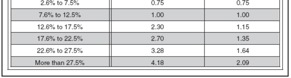
26 Page 4C Edition Revision 2 The minor-street approach volume may be multiplied by up to three adjustment factors as provided in the next three paragraphs. Because the curves are based on an average of four occurrences of rail traffic per day, the vehicles per hour on the minor-street approach may be multiplied by the adjustment factor shown in Table 4C-2 for the appropriate number of occurrences of rail traffic per day. Because the curves are based on typical vehicle occupancy, if at least 2% of the vehicles crossing the track are buses carrying at least 20 people, the vehicles per hour on the minor-street approach may be multiplied by the adjustment factor shown in Table 4C-3 for the appropriate percentage of high-occupancy buses. Because the curves are based on tractor-trailer trucks comprising 10% of the vehicles crossing the track, the vehicles per hour on the minor-street approach may be multiplied by the adjustment factor shown in Table 4C-4 for the appropriate distance and percentage of tractor-trailer trucks. If this warrant is met and a traffic control signal at the intersection is justified by an engineering study, then: A. The traffic control signal shall have actuation on the minor street; B. Preemption control shall be provided in accordance with Sections 4D.13, 8D.07, and 10D.06; and C. The grade crossing shall have flashing-light signals (see Chapters 8D and 10D). If this warrant is met and a traffic control signal at the intersection is justified by an engineering study, the grade crossing should have automatic gates (see Chapters 8D and 10D).


27 2005 Edition Revision 2 Page 4C - 15 Figure 4C-9. Warrant 9, Intersection Near a Grade Crossing (One Approach Lane at the Track Crossing) English units only Figure 4C-10. Warrant 9, Intersection Near a Grade Crossing (Two or More Approach Lanes at the Track Crossing) English units only


28 Page 4C Edition Revision 2
29 2005 Edition Page 4D - 1 Section 4D.01 General CHAPTER 4D. TRAFFIC CONTROL SIGNAL FEATURES The features of traffic control signals of interest to road users are the location, design, and meaning of the signal indications. Uniformity in the design features that affect the traffic to be controlled, as set forth in this Manual, is especially important for reasonably safe and efficient traffic operations. Pavement markings (see Part 3) that clearly communicate the operational plan of an intersection to road users play an important role in the effective operation of traffic control signals. By designating the number of lanes, the use of each lane, the length of additional lanes on the approach to an intersection, and the proper stopping points, the engineer can design the signal phasing and timing to best match the goals of the operational plan. A traffic control signal shall control traffic only at the intersection or midblock location where the signal faces are placed. STOP signs shall not be used in conjunction with any traffic control signal operation, except in either of the following cases: A. If the signal indication for an approach is a flashing red at all times; or B. If a minor street or driveway is located within or adjacent to the area controlled by the traffic control signal, but does not require separate traffic signal control because an extremely low potential for conflict exists. When a traffic control signal is not in operation, such as before it is placed in service, during seasonal shutdowns, or when it is not desirable to operate the traffic control signal, the signal faces shall be covered, turned, or taken down to clearly indicate that the traffic control signal is not in operation. Midblock crosswalks shall not be signalized if they are located within 90 m (300 ft) from the nearest traffic control signal, unless the proposed traffic control signal will not restrict the progressive movement of traffic. Midblock crosswalks should not be signalized if they are located within 30 m (100 ft) from side streets or driveways that are controlled by STOP signs or YIELD signs. Pavement markings should be used at traffic control signal locations as provided in Part 3. If the road surface will not retain pavement markings, signs should be installed to provide the needed road user information. Engineering judgment should be used to determine the proper phasing and timing for a traffic control signal. Since traffic flows and patterns change, phasing and timing should be reevaluated regularly and updated if needed. Section 4D.02 Responsibility for Operation and Maintenance Prior to installing any traffic control signal, the responsibility for the maintenance of the signal and all of the appurtenances, hardware, software, and the timing plan(s) should be clearly established. The responsible agency should provide for the maintenance of the traffic control signal and all of its appurtenances in a competent manner.
30 Page 4D Edition To this end the agency should: A. Keep every controller assembly in effective operation in accordance with its predetermined timing schedule; check the operation of the controller assembly frequently enough to verify that it is operating in accordance with the predetermined timing schedule; and establish a policy to maintain a record of all timing changes and that only authorized persons are permitted to make timing changes; B. Clean the optical system of the signal sections and replace the light sources as frequently as experience proves necessary; C. Clean and service equipment and other appurtenances as frequently as experience proves necessary; D. Provide for alternate operation of the traffic control signal during a period of failure, using flashing mode or manual control, or manual traffic direction by proper authorities as might be required by traffic volumes or congestion, or by erecting other traffic control devices; E. Have properly skilled maintenance personnel available without undue delay for all emergency and lamp failure calls; F. Provide spare equipment to minimize the interruption of traffic control signal operation as a result of equipment failure; G. Provide for the availability of properly skilled maintenance personnel for the repair of all components; and H. Maintain the appearance of the signal displays and equipment. Section 4D.03 Provisions for Pedestrians Chapter 4E contains additional information regarding pedestrian signals. The design and operation of traffic control signals shall take into consideration the needs of pedestrian as well as vehicular traffic. If engineering judgment indicates the need for provisions for a given pedestrian movement, signal faces conveniently visible to pedestrians shall be provided by pedestrian signal heads or a signal face for an adjacent vehicular movement. Safety considerations should include the installation, where appropriate, of accessible pedestrian signals (see Sections 4E.06 and 4E.09) that provide information in nonvisual format (such as audible tones, verbal messages, and/or vibrating surfaces). Where pedestrian movements regularly occur, pedestrians should be provided with sufficient time to cross the roadway by adjusting the traffic control signal operation and timing to provide sufficient crossing time every cycle or by providing pedestrian detectors. If it is desirable to prohibit certain pedestrian movements at a traffic control signal, a PEDESTRIANS PROHIBITED (R9-3) or No Pedestrian Crossing (R9-3a) sign may be used (see Section 2B.44). Section 4D.04 Meaning of Vehicular Signal Indications The Ohio Revised Code is the primary source for the standards for the meaning of vehicular signal indications to both vehicle operators and pedestrians as set forth below, and the standards for the meaning of separate pedestrian signal indications as set forth in Section 4E.02. As specified in and of the Ohio Revised Code, the following meanings shall be given to highway traffic signal indications, except those for Pedestrian Signals (see Section 4E.01) and Lane-Use Control Signals (see Section 4J.02):
31 2005 Edition Page 4D - 3 [from O.R.C. Section ] (A) Green indication: (1) Vehicular traffic, streetcars, and trackless trolleys facing a circular green signal may proceed straight through or turn right or left unless a sign at such place prohibits either such turn. But vehicular traffic, streetcars, and trackless trolleys, including vehicles, streetcars, and trackless trolleys turning right or left, shall yield the right-of-way to other vehicles, streetcars, trackless trolleys, and pedestrians lawfully within the intersection or an adjacent crosswalk at the time such signal is exhibited. (2) Vehicular traffic, streetcars, and trackless trolleys facing a green arrow signal, shown alone or in combination with another indication, may cautiously enter the intersection only to make the movement indicated by such arrow, or such other movement as is permitted by other indications shown at the same time. Such vehicular traffic, streetcars, and trackless trolleys shall yield the right-of-way to pedestrians lawfully within an adjacent crosswalk and to other traffic lawfully using the intersection. (3) Unless otherwise directed by a pedestrian-control signal, as provided in section of the Revised Code, pedestrians facing any green signal, except when the sole green signal indication is a turn arrow, may proceed across the roadway within any marked or unmarked crosswalk. (B) Steady yellow indication: (1) Vehicular traffic, streetcars, and trackless trolleys facing a steady circular yellow or yellow arrow signal indication are thereby warned that the related green movement is being terminated or that a red indication will be exhibited immediately thereafter when vehicular traffic, streetcars, and trackless trolleys shall not enter the intersection. (2) Pedestrians facing a steady circular yellow or yellow arrow signal, unless otherwise directed by a pedestrian-control signal as provided in section of the Revised Code, are thereby advised that there is insufficient time to cross the roadway before a red indication is shown and no pedestrian shall then start to cross the roadway. (C) Steady red indication: (1) Vehicular traffic, streetcars, and trackless trolleys facing a steady red signal alone shall stop at a clearly marked stop line, but if none, before entering the crosswalk on the near side of the intersection, or if none, then before entering the intersection and shall remain standing until an indication to proceed is shown, except as provided in divisions (C)(2) and (3) of this section. (2) Unless a sign is in place prohibiting a right turn as provided in division (C)(5) of this section, vehicular traffic, streetcars, and trackless trolleys facing a steady red signal may cautiously enter the intersection to make a right turn after stopping as required by division (C)(1) of this section. Such vehicular traffic, streetcars, and trackless trolleys shall yield the right-of-way to pedestrians lawfully within an adjacent crosswalk and to other traffic lawfully using the intersection. (3) Unless a sign is in place prohibiting a left turn as provided in division (C)(5) of this section, vehicular traffic, streetcars, and trackless trolleys facing a steady red signal on a one-way street that intersects another one-way street on which traffic moves to the left may cautiously enter the intersection to make a left turn into the one-way street after stopping as required by division (C)(1) of this section, and yielding the right-of-way to pedestrians lawfully within an adjacent crosswalk and to other traffic lawfully using the intersection. (4) Unless otherwise directed by a pedestrian-control signal as provided in section of the Revised Code, pedestrians facing a steady red signal alone shall not enter the roadway. (5) Local authorities may by ordinance, or the director of transportation on state highways may, prohibit a right or a left turn against a steady red signal at any intersection, which shall be effective when signs giving notice thereof are posted at the intersection. (See Section 2B.45 for further information.) (D) In the event an official traffic control signal is erected and maintained at a place other than an intersection, the provisions of this section shall be applicable except as to those provisions which by their nature can have no application. Any stop required shall be made at a sign or marking on the pavement indicating where the stop shall be made, but in the absence of any such sign or marking the stop shall be made at the signal.
32 Page 4D Edition [from O.R.C. Section ] (A) Flashing red stop signal: Operators of vehicles, trackless trolleys, and streetcars shall stop at a clearly marked stop line, but if none, before entering the crosswalk on the near side of the intersection, or if none, then at the point nearest the intersecting roadway where the driver has a view of approaching traffic on the intersecting roadway before entering it, and the right to proceed shall be subject to the rules applicable after making a stop at a stop sign. (B) Flashing yellow caution signal: Operators of vehicles, trackless trolleys, and streetcars may proceed through the intersection or past such signal only with caution. Section 4D.05 Application of Steady Signal Indications When a traffic control signal is being operated in a steady (stop-and-go) mode, at least one lens in each signal face shall be illuminated at any given time. A signal face(s) that controls a particular vehicular movement during any interval of a cycle shall control that same movement during all intervals of the cycle. Steady signal indications shall be applied as follows: A. A steady CIRCULAR RED signal indication: 1. Shall be displayed when it is intended to prohibit traffic, except pedestrians directed by a pedestrian signal head, from entering the intersection or other controlled area. Turning after stopping is permitted as stated in Item C.1 of Section 4D Shall be displayed with the appropriate GREEN ARROW signal indications when it is intended to permit traffic to make a specified turn or turns, and to prohibit traffic from proceeding straight ahead through the intersection or other controlled area, except in protected only mode turn signal faces, or in protected/permissive mode left-turn operation with separate left-turn signal faces (see Section 4D.06). B. A steady CIRCULAR YELLOW signal indication: 1. Shall be displayed following a CIRCULAR GREEN or straight-through GREEN ARROW signal indication in the same signal face. 2. Shall not be displayed in conjunction with the change from the CIRCULAR RED signal indication to the CIRCULAR GREEN signal indication. 3. Shall be followed by a CIRCULAR RED signal indication except that, when entering preemption operation, the return to the previous CIRCULAR GREEN signal indication shall be permitted following a CIRCULAR YELLOW signal indication (see Section 4D.13). 4. Shall not be displayed to an approach from which drivers are turning left permissively unless one of the following conditions exists: (a) A steady CIRCULAR YELLOW signal indication is also being shown simultaneously to the opposing approach; (b) A separate left-turn signal face is provided and operated as described in Section 4D.06; (c) An engineering study has determined that, because of unique intersection conditions, the conditions described in items (a) and (b) above cannot reasonably be implemented without causing significant operational or safety problems and that the volume of impacted left-turning traffic is relatively low, and those left-turning drivers are advised that the opposing traffic is not simultaneously being shown a CIRCULAR YELLOW signal indication if this operation occurs continuously by the installation near the left-most signal head of a W25-1 sign (see Section 2C.39) with the legend ONCOMING TRAFFIC HAS EXTENDED GREEN; or (d) Drivers are advised of the operation if it occurs only occasionally, such as during a preemption sequence or because of the skipping of actuated phases, by the installation
33 2005 Edition Page 4D - 5 near the left-most signal head of a W25-2 sign (see Section 2C.39) with the legend ONCOMING TRAFFIC MAY HAVE EXTENDED GREEN. C. A steady CIRCULAR GREEN signal indication shall be displayed only when it is intended to permit traffic to proceed in any direction that is lawful and practical. D. A steady YELLOW ARROW signal indication: 1. Shall be displayed in the same direction as a GREEN ARROW signal indication following a GREEN ARROW signal indication in the same signal face, unless: (a) The GREEN ARROW signal indication and a CIRCULAR GREEN (or straightthrough GREEN ARROW) signal indication terminate simultaneously in the same signal face, or (b) The green arrow is a straight-through GREEN ARROW. 2. Shall not be displayed when any conflicting vehicular movement has a green or yellow signal indication or any conflicting pedestrian movement has a WALKING PERSON (symbolizing WALK) or flashing UPRAISED HAND (symbolizing DONT WALK) signal indication (see Section 4D.09). 3. Shall be terminated by a CIRCULAR RED signal indication except: (a) When entering preemption operation, the return to the previous GREEN ARROW signal indication shall be permitted following a YELLOW ARROW signal indication. (b) When the movement controlled by the arrow is to continue on a permissive mode basis during an immediately following CIRCULAR GREEN signal indication. E. A steady GREEN ARROW signal indication: 1. Shall be displayed only to allow vehicular movements, in the direction indicated, that are not in conflict with other vehicles moving on a green or yellow signal indication or with pedestrians crossing in conformance with a WALKING PERSON (symbolizing WALK) or flashing UPRAISED HAND (symbolizing DONT WALK) signal indication (see Section 4D.09). 2. Shall be displayed on a signal face that controls a left-turn movement when said movement is not in conflict with other vehicles moving on a green or yellow signal indication or with pedestrians crossing in conformance with a WALKING PERSON (symbolizing WALK) or flashing UPRAISED HAND (symbolizing DONT WALK) signal indication (see Section 4D.09). 3. Shall not be required on the stem of T-intersections or for turns from one-way streets. Steady YELLOW ARROW and GREEN ARROW signal indications, if not otherwise prohibited, may be used instead of the corresponding circular signal indications at the following locations: A. On an approach intersecting a one-way street; B. Where certain movements are prohibited; and C. Where certain movements are physically impossible. If U-turns are permitted from the approach and if drivers making a right turn from the conflicting approach to the left are simultaneously being shown a right-turn GREEN ARROW signal indication, drivers making a U-turn may be advised of the operation by the installation near the left-turn signal face of a U- TURN YIELD TO RIGHT TURN (R10-16) sign (see Section 2B.45). Section 4D.06 Application of Steady Signal Indications for Left Turns Left-turning traffic is controlled by one of four modes as follows: A. Permissive Only Mode turns made on the CIRCULAR GREEN signal indication after yielding to oncoming traffic and pedestrians; B. Protected Only Mode turns made only when the left-turn GREEN ARROW signal indication is displayed; C. Protected/Permissive Mode both modes occur on an approach during the same cycle; or
34 Page 4D Edition D. Variable Left-Turn Mode the operating mode changes among the protected only mode and/or the protected/permissive mode and/or the permissive only mode during different periods of the day. In areas having a high percentage of elderly drivers, special consideration may be given to the use of protected only mode left-turn phasing, when appropriate. The required left-turn signal faces and operation for an approach shall be determined by the selected mode of left-turn operation, as follows: A. Permissive Only Mode The signal indications for permissive only mode left turns shall be provided by the signal faces controlling the through movement, or by a permissive-only leftturn signal face that is either a shared signal face or a separate signal face. A permissive-only shared signal face, regardless of where the permissive-only left-turn signal face is positioned and regardless of how many adjacent through signal faces are provided, shall always simultaneously display the same color of circular indication that the adjacent through signal face or faces display. A separate permissive-only left-turn signal face sometimes displays a different color of circular signal indication than the adjacent through signal faces display. If a separate left-turn signal face is provided for permissive only left turns, it shall meet the following requirements: 1. During the permissive left-turn movement, the left-turn signal face shall display a CIRCULAR GREEN signal indication. 2. If the CIRCULAR GREEN and CIRCULAR YELLOW signal indications in the left-turn signal face are visibility-limited from the adjacent through movement, the left-turn signal face shall not be required to simultaneously display the same color of circular signal indication as the signal faces for the adjacent through movement. 3. If the CIRCULAR GREEN and CIRCULAR YELLOW signal indications in the left-turn signal face are visibility-limited from the adjacent through movement, the display of a CIRCULAR GREEN signal indication for a permissive left-turn movement while the signal faces for the adjacent through movement display CIRCULAR RED signal indications and the opposing left-turn signal faces display left-turn GREEN ARROW signal indications for a protected left-turn movement shall be permitted. 4. If the left-turn signal face does not simultaneously display the same color of circular signal indication as the signal faces for the adjacent through movement, a LEFT TURN YIELD ON GREEN (symbolic green ball) (R10-12) sign or a LEFT TURN SIGNAL YIELD ON GREEN (symbolic green ball) (R10-21) sign (see Figure 2B-19) shall be used. B. Protected Only Mode The left-turn signal face shall be capable of displaying one of the following sets of signal indications: 1. CIRCULAR RED, left-turn YELLOW ARROW, and left-turn GREEN ARROW signal indications. At least one left-turn signal face shall be provided in addition to the two approach signal faces required in Section 4D.15 for the major movement. Only one of the three colors shall be illuminated at any given time. Unless the CIRCULAR RED signal indication is shielded, hooded, louvered, positioned, or designed such that it is not readily visible to drivers in the through lane(s), a LEFT TURN SIGNAL sign (R10-10L) shall be used. 2. CIRCULAR RED, CIRCULAR YELLOW, CIRCULAR GREEN, and left-turn GREEN ARROW signal indications. This four-section signal face shall be used only when the CIRCULAR GREEN and left-turn GREEN ARROW signal indications begin and terminate together. During each interval, the circular signal indication shall be the same color as the signal indication on the signal face(s) for the adjacent through traffic. C. Protected/Permissive Mode The signal indications for protected/permissive mode left turns shall be provided in either a shared signal face or a separate signal face. Any protected/permissive left-turn signal face that always simultaneously displays the same color
35 2005 Edition Page 4D - 7 of circular signal indication that the adjacent through signal faces display shall be considered to be a shared signal face, regardless of where the left-turn signal face is positioned and regardless of how many adjacent through signal faces are provided. Any protected/permissive left-turn signal face that sometimes displays a different color of circular signal indication than the adjacent through signal faces display shall be considered to be a separate signal face. The requirements for each type of signal face are as follows: 1. If a shared signal face is provided, it shall be considered an approach signal face, and shall meet the following requirements: (a) During the protected left-turn movement, the signal face shall simultaneously display a left-turn GREEN ARROW signal indication and a circular signal indication that is the same color as the signal indication for the adjacent through lane on the same approach as the protected left turn. During the protected left-turn movement, the signal faces for through traffic on the opposing approach shall simultaneously display CIRCULAR RED signal indications. (b) During the permissive left-turn movement, all signal faces on the approach shall display CIRCULAR GREEN signal indications. (c) All signal faces on the approach shall simultaneously display the same color of circular signal indications to both through and left-turn road users. (d) A supplementary sign shall not be required. If used, it shall be a LEFT TURN YIELD ON GREEN (symbolic green ball) (R10-12) sign (see Figure 2B-19). 2. If a separate signal face is provided, it shall be considered a left-turn signal face, and shall meet the following requirements: (a) During the protected left-turn movement, the left-turn signal face shall display a leftturn GREEN ARROW signal indication. During the protected left-turn movement, the signal faces for through traffic on the opposing approach shall simultaneously display CIRCULAR RED signal indications. (b) During the permissive left-turn movement, the left-turn signal face shall display a CIRCULAR GREEN signal indication. (c) If the CIRCULAR GREEN and CIRCULAR YELLOW signal indications in the leftturn signal face are visibility-limited from the adjacent through movement, the leftturn signal face shall not be required to simultaneously display the same color of circular signal indication as the signal faces for the adjacent through movement. (d) If the CIRCULAR GREEN and CIRCULAR YELLOW signal indications in the leftturn signal face are visibility-limited from the adjacent through movement, the display of a CIRCULAR GREEN signal indication for a permissive left-turn movement while the signal faces for the adjacent through movement display CIRCULAR RED signal indications and the opposing left-turn signal face displays a left-turn GREEN ARROW for a protected left-turn movement shall be permitted. (e) If the left-turn signal face does not simultaneously display the same color of circular signal indication as the signal faces for the adjacent through movement, a LEFT TURN SIGNAL YIELD ON GREEN (symbolic green ball) (R10-21) sign (see Figure 2B-19) shall be used. D. Variable Left-Turn Mode If the protected only mode occurs during one or more periods of the day, and the permissive only mode or the combined protected/permissive mode occurs during other periods of the day, the requirements of Items A, B, and C in this Standard that are appropriate to that mode of operation shall be met, subject to the following: 1. The CIRCULAR GREEN and CIRCULAR YELLOW signal indications shall not be displayed when operating in the protected only mode. 2. The left-turn GREEN ARROW and left-turn YELLOW ARROW signal indications shall not be displayed when operating in the permissive only mode.
36 Page 4D Edition Additional appropriate signal indications or changeable message signs may be used to meet the requirements for the variable left-turn mode. Section 4D.07 Application of Steady Signal Indications for Right Turns Right-turning traffic is controlled by one of four modes as follows: A. Permissive Only Mode turns made on the CIRCULAR GREEN signal indication after yielding to pedestrians. B. Protected Only Mode turns made only when the right-turn GREEN ARROW signal indication is displayed. C. Protected/Permissive Mode both modes occur on an approach during the same cycle. D. Variable Right-Turn Mode the operating mode changes among the protected only mode and/or the protected/permissive mode and/or the permissive only mode during different periods of the day. The required right-turn signal faces and operation for an approach shall be determined by the selected mode of right-turn operation, as follows: A. Permissive Only Mode A separate signal indication or signal face for right turns shall not be required. The signal indication for permissive only mode right turns shall be the same color as the signal indication for adjacent through traffic. B. Protected Only Mode The right-turn signal face shall be capable of displaying one of the following sets of signal indications: 1. CIRCULAR RED, right-turn YELLOW ARROW, and right-turn GREEN ARROW signal indications. At least one right-turn signal face shall be provided in addition to the two approach signal faces required in Section 4D.15 for the major movement. Only one of three colors shall be illuminated at any given time. Unless the CIRCULAR RED signal indication is shielded, hooded, louvered, positioned, or designed such that it is not readily visible to drivers in the through lane(s), a RIGHT TURN SIGNAL sign (R10-10R) shall be used. 2. CIRCULAR RED, CIRCULAR YELLOW, CIRCULAR GREEN, and right-turn GREEN ARROW signal indications. This four-section signal face shall be used only when the CIRCULAR GREEN and right-turn GREEN ARROW signal indications begin and terminate together. During each interval, the circular signal indication shall be the same color as the signal indication on the signal faces for the adjacent through traffic. C. Protected/Permissive Mode A separate signal face is not required for the right turn, but, if provided, it shall be considered an approach signal face, and shall meet the following requirements: 1. During the protected right-turn movement, the signal face shall simultaneously display: (a) A right-turn GREEN ARROW signal indication, and (b) A circular signal indication that is the same color as the signal indication for the adjacent through lane on the same approach as the protected right turn. 2. During the permissive right-turn movement, all signal faces on the approach shall display a CIRCULAR GREEN signal indication. 3. All signal faces on the approach shall simultaneously display the same color of circular signal indications to both through and right-turn road users. D. Variable Right-Turn Mode If the protected only mode occurs during one or more periods of the day, and the permissive only mode or the combined protected/permissive mode occurs during other periods of the day, the requirements of Items A, B, and C in this Standard that are appropriate to that mode of operation shall be met subject to the following:
37 2005 Edition Page 4D The CIRCULAR GREEN and CIRCULAR YELLOW signal indications shall not be displayed when operating in the protected only mode. 2. The right-turn GREEN ARROW and right-turn YELLOW ARROW signal indications shall not be displayed when operating in the permissive only mode. Additional appropriate signal indications or changeable message signs may be used to meet the requirements for the variable right-turn mode. Section 4D.08 Prohibited Steady Signal Indications The following combinations of signal indications shall not be simultaneously displayed on any one signal face: A. CIRCULAR GREEN with CIRCULAR YELLOW. B. CIRCULAR RED with CIRCULAR YELLOW. C. CIRCULAR GREEN with CIRCULAR RED. D. Straight-through GREEN ARROW with CIRCULAR RED. The above combinations shall not be simultaneously displayed in different signal faces on any one approach unless one of the following conditions exists: A. One of the signal faces is a turn signal controlling a protected only mode turn, and a LEFT (RIGHT) TURN SIGNAL sign (R10-10) (see Sections 4D.06 and 4D.07) is mounted adjacent to each such signal face, or B. The signal faces are shielded, hooded, louvered, positioned, or designed so that the combination is not confusing to approaching road users. A RED ARROW signal indication or a straight-through YELLOW ARROW signal indication shall not be displayed on any signal face, either alone or in combination with any other signal indication. Section 4D.09 Unexpected Conflicts During Green or Yellow Intervals A steady GREEN ARROW or YELLOW ARROW signal indication shall not be displayed to vehicular movements that are in conflict with the following: A. Other vehicles moving on a green or yellow signal indication, except for the situation regarding U-turns described in Section 4D.05. Vehicles departing in the same direction shall not be considered in conflict if, for each turn lane with moving traffic, there is a separate departing lane, and pavement markings or raised channelization clearly indicate which departure lane to use. B. Pedestrians crossing in conformance with a WALKING PERSON (symbolizing WALK) or flashing UPRAISED HAND (symbolizing DONT WALK) signal indication. No movement that creates an unexpected crossing of pathways of moving vehicles or pedestrians should be allowed during any green or yellow interval, except when all three of the following conditions are met: A. The movement involves only slight conflict, and B. Serious traffic delays are substantially reduced by permitting the conflicting movement, and C. Drivers and pedestrians subjected to the unexpected conflict are effectively warned thereof by a sign.
38 Page 4D Edition Section 4D.10 Yellow Change and Red Clearance Intervals A yellow signal indication shall be displayed following every CIRCULAR GREEN or GREEN ARROW signal indication. The exclusive function of the yellow change interval shall be to warn traffic of an impending change in the right-of-way assignment. The duration of a yellow change interval shall be predetermined. A yellow change interval should have a duration of approximately 3 to 6 seconds. The longer intervals should be reserved for use on approaches with higher speeds. The yellow change interval may be followed by a red clearance interval to provide additional time before conflicting traffic movements, including pedestrians, are released. The duration of a red clearance interval shall be predetermined. A red clearance interval should have a duration not exceeding 6 seconds. Section 4D.11 Application of Flashing Signal Indications The light source of a flashing signal indication shall be flashed continuously at a rate of not less than 50 nor more than 60 times per minute. The illuminated period of each flash shall be not less than half and not more than two-thirds of the total flash cycle. Flashing signal indications shall comply with the requirements of other Sections of this Manual regarding shielding or positioning of conflicting signal indications, except that flashing yellow signal indications for through traffic shall not be required to be shielded or positioned to prevent visual conflict for road users in separately controlled turn lanes. The following applications shall apply whenever a traffic control signal is operated in the flashing mode: A. Each approach or protected only mode turn movement that is controlled during steady mode (stop-and-go) operation shall display a signal indication during flashing operation. B. All signal faces that are flashed on an approach shall flash the same color, either yellow or red, except that separate signal faces for protected only mode turn movements and separate signal faces for protected/permissive left-turn movements shall be permitted to flash a CIRCULAR RED signal indication when the through signal indications are flashed yellow. Shared signal faces for protected/permissive left-turn movements shall not be permitted to flash a CIRCULAR RED signal indication when the through signal indications are flashed yellow. C. If a signal face includes both circular and arrow signal lenses of the color that is to be flashed, only the circular signal indication shall be flashed. When a traffic control signal is operated in the flashing mode, a flashing yellow signal indication should be used for the major street and a flashing red signal indication should be used for the other approaches unless flashing red signal indications are used on all approaches.
39 2005 Edition Page 4D - 11 Section 4D.12 Flashing Operation of Traffic Control Signals Each traffic control signal shall be provided with an independent flasher mechanism that operates in compliance with Section 4D.11. The flashing operation shall not be terminated by removal or turn off of the controller unit or of the conflict monitor (malfunction management unit) or both. When a traffic control signal is operated in the flashing mode: A. Flashing yellow signal indications shall not be displayed for approaches with conflicting traffic movements, except for permissive left-turn movements. B. At least one signal indication in each signal face on an approach shall be flashed except in the following circumstance: A single-section signal face consisting of a continuously-illuminated GREEN ARROW signal lens that is used alone to indicate a continuous movement in the steady (stop-and-go) mode shall remain continuously illuminated when the traffic control signal is operated in the flashing mode. A manual switch, a conflict monitor (malfunction management unit) circuit, and, if appropriate, automatic means shall be provided to initiate the flashing mode. The transition from steady (stop-and-go) mode to flashing mode, if initiated by a conflict monitor (malfunction management unit) or by a manual switch, shall be permitted to be made at any time. Programmed changes from steady (stop-and-go) mode to flashing mode shall be made under either of the following circumstances: A. At the end of the common major-street red interval (such as just prior to the start of the green in both directions on the major street), or B. Directly from a steady CIRCULAR GREEN or GREEN ARROW signal indication to a flashing CIRCULAR YELLOW or YELLOW ARROW signal indication, respectively. During programmed changes, no steady green signal indication or flashing yellow signal indication shall be terminated and immediately followed by a steady red or flashing red signal indication without first displaying the steady yellow signal indication. Changes from flashing mode to steady (stop-and-go) mode shall be made under one of the following procedures: A. Yellow-red flashing mode: Changes from flashing mode to steady (stop-and-go) mode shall be made at the beginning of the major-street green interval (when a green signal indication is shown to through traffic in both directions on the major street), or if there is no common major-street green interval, at the beginning of the green interval for the major traffic movement on the major street. B. Red-red flashing mode: Changes from flashing mode to steady (stop-and-go) mode shall be made by changing the flashing red indications to steady red indications followed by appropriate green indications to begin the steady mode cycle. These green indications shall be the beginning of the major-street green interval (when a green signal indication is shown to through traffic in both directions on the major street) or if there is no common major-street green interval, at the beginning of the green interval for the major traffic movement on the major street. When changing from the yellow-red flashing mode to steady (stop-and-go) mode, if there is no common major-street green interval, the provision of a steady red clearance interval for the other approaches before changing from a flashing yellow or a flashing red signal indication to a green signal indication on the major approach should be considered.
40 Page 4D Edition The steady red clearance interval provided during the change from red-red flashing mode to steady (stop-and-go) mode should have a duration of 6 seconds. Section 4E.09 contains information regarding the operation of accessible pedestrian signal detector pushbutton locator tones during flashing operation. Section 4D.13 Preemption and Priority Control of Traffic Control Signals Traffic control signals may be designed and operated to respond to certain classes of approaching vehicles by altering the normal signal timing and phasing plan(s) during the approach and passage of those vehicles. The alternative plan(s) may be as simple as extending a currently displayed green interval or as complex as replacing the entire set of signal phases and timing. Preemption control (see definition in Section 4A.02) is typically given to trains, boats, emergency vehicles and light rail transit. Examples of preemption control include the following: A. The prompt displaying of green signal indications at signalized locations ahead of fire vehicles, law enforcement vehicles, ambulances, and other official emergency vehicles; B. A special sequence of signal phases and timing to provide additional clearance time for vehicles to clear the tracks prior to the arrival of a train; and C. A special sequence of signal phases to display a red indication to prohibit turning movements towards the tracks during the approach or passage of a train or transit vehicle. Priority control (see definition in Section 4A.02) is typically given to certain nonemergency vehicles such as buses and light-rail vehicles. Examples of priority control include the following: A. The displaying of early or extended green signal indications at an intersection to assist public transit vehicles in remaining on schedule; and B. Special phasing to assist public transit vehicles in entering the travel stream ahead of the platoon of traffic. Some types or classes of vehicles supersede others when a traffic control signal responds to more than one type or class. In general, a vehicle that is more difficult to control supersedes a vehicle that is easier to control. Typically, the order of priority is: train, boat, heavy vehicle (fire vehicle, emergency medical service), light vehicle (law enforcement), light rail transit, rubber-tired transit. During the transition into preemption control: A. The yellow change interval, and any red clearance interval that follows, shall not be shortened or omitted. B. The shortening or omission of any pedestrian walk interval and/or pedestrian change interval shall be permitted. C. The return to the previous steady green signal indication shall be permitted following a steady yellow signal indication in the same signal face, omitting the red clearance interval, if any. During preemption control and during the transition out of preemption control: A. The shortening or omission of any yellow change interval, and of any red clearance interval that follows, shall not be permitted. B. A signal indication sequence from a steady yellow signal indication to a steady green signal indication shall not be permitted.
41 2005 Edition Page 4D - 13 During priority control and during the transition into or out of priority control: A. The shortening or omission of any yellow change interval, and of any red clearance interval that follows, shall not be permitted. B. The shortening of any pedestrian walk interval below that time described in Section 4E.10 shall not be permitted. C. The omission of a pedestrian walk interval and its associated change interval shall not be permitted unless the associated vehicular phase is also omitted or the pedestrian phase is exclusive. D. The shortening or omission of any pedestrian change interval shall not be permitted. E. A signal indication sequence from a steady yellow signal indication to a steady green signal indication shall not be permitted. When a traffic control signal that is returning to a steady mode from a dark mode (typically upon restoration from a power failure) receives a preemption or priority request, care should be exercised to minimize the possibility of vehicles or pedestrians being misdirected into a conflict with the vehicle making the request. If a traffic control signal is installed near or within a highway-railroad grade crossing or if a highwayrailroad grade crossing with active traffic control devices is within or near a signalized highway intersection, Chapter 8D should be consulted. Traffic control signals operating under preemption control or under priority control should be operated in a manner designed to keep traffic moving. Traffic control signals that are designed to respond under preemption or priority control to more than one type or class of vehicle should be designed to respond in the relative order of importance or difficulty in stopping the type or class of vehicle. During the change from a dark mode to a steady mode under a preemption or priority request, the display of signal indications that could misdirect road users may be prevented by the following: A. Having the traffic control signal remain in the dark mode; B. Having the traffic control signal remain in the flashing mode; C. Altering the flashing mode; D. Executing the normal start-up routine before responding; and E. Responding directly to initial or dwell period. A distinctive indication may be provided at the intersection to show that an emergency vehicle has been given control of the traffic control signal. Preemption or priority control of traffic control signals may also be a means of assigning priority rightof-way to specified classes of vehicles at certain nonintersection locations such as on approaches to one-lane bridges and tunnels, movable bridges, highway maintenance and construction activities, metered freeway entrance ramps, and transit operations. Section 4D.14 Coordination of Traffic Control Signals Traffic control signals within 800 m (0.5 mi) of one another along a major route or in a network of intersecting major routes should be coordinated, preferably with interconnected controller units. However, signal coordination need not be maintained across boundaries between signal systems that operate on different cycle lengths. For coordination with railroad-highway grade crossing signals, see Sections 4D.13 and 8D.07.
42 Page 4D Edition Section 4D.15 Size, Number, and Location of Signal Faces by Approach Sections 4D.05, and 4D.16 through 4D.18 contain additional information regarding the design of signal faces. There shall be two nominal diameter sizes for vehicular signal lenses: 200 mm (8 in) and 300 mm (12 in). Three-hundred millimeter (12 in) signal lenses shall be used: A. For signal indications for approaches (see definition in Section 4A.02) where road users view both traffic control and lane-use control signal heads simultaneously; B. If the nearest signal face is between 35 m (120 ft) and 45 m (150 ft) beyond the stop line, unless a supplemental near-side signal face is provided; C. For signal faces located more than 45 m (150 ft) from the stop line; D. For approaches to all signalized locations for which the minimum sight distance in Table 4D-1 cannot be met; and E. For arrow signal indications. A 200 mm (8 in) signal lens for a CIRCULAR RED signal indication shall not be used in combination with a 300 mm (12 in) signal lens for a CIRCULAR GREEN signal indication or a 300 mm (12 in) signal lens for a CIRCULAR YELLOW signal indication. Different sizes of signal lenses may be used in the same signal face or signal head, except for the prohibitions listed in the Standards in this Section. Three-hundred millimeter (12 in) signal lenses should be used for all signal indications for the following: A. Approaches with 85th-percentile approach speeds exceeding 60 km/h (40 mph); B. Approaches where a traffic control signal might be unexpected; C. All approaches without curbs and gutters where only post-mounted signal heads are used; and D. Locations where there is a significant percentage of elderly drivers. The signal faces for each approach to an intersection or a midblock location shall be provided as follows: A. A minimum of two signal faces shall be provided for the major movement on the approach, even if the major movement is a turning movement. B. See Section 4D.06 for left-turn signal faces. C. See Section 4D.07 for right-turn signal faces. D. Except where the width of an intersecting roadway or other conditions make it physically impractical: 1. A signal face installed to satisfy the requirements for left-turn signal faces (see Section 4D.06) and right-turn signal faces (see Section 4D.07), and at least one and preferably both of the two signal faces required for the major movement on the approach shall be located: (a) Not less than 12 m (40 ft) beyond the stop line. (b) Not more than 55 m (180 ft) beyond the stop line unless a supplemental near side signal face is provided. (c) As near as practical to the line of the driver's normal view, if mounted over the roadway.
43 2005 Edition Page 4D Where the nearest signal face is located between 45 and 55 m (150 and 180 ft) beyond the stop line, engineering judgment of the conditions, including the worst-case visibility conditions, shall be used to determine if the provision of a supplemental near side signal face would be beneficial. 3. A signal face installed to satisfy the requirements for left-turn signal faces (see Section 4D.06) and right-turn signal faces (see Section 4D.07), and at least one and preferably both of the two signal faces required for the major movement on the approach shall be located no higher than at a maximum height to the top of the signal housing mounted over a roadway of 7.8 m (25.6 ft) above the pavement (see Section 4D.17). For viewing distances between 12 m (40 ft) and 16 m (53 ft) from the stop line, the maximum mounting height to the top of the signal housing shall be as shown on Figure 4D-1. (See Section 4D.17 for additional information regarding mounting heights.) 4. At least one and preferably both of the signal faces required by Item A in this Standard shall be located between two lines intersecting with the center of the approach at a point 3 m (10 ft) behind the stop line, one making an angle of approximately 20 degrees to the right of the center of the approach extended, and the other making an angle of approximately 20 degrees to the left of the center of the approach extended (see Figure 4D- 2) 5. If both of the signal faces required by Item A in this Standard are post-mounted, they shall both be on the far side of the intersection, one on the right and one on the left of the approach lane(s). E. If the minimum sight distance in Table 4D-1 cannot be met, a sign shall be installed to warn approaching traffic of the traffic control signal. F. Required signal faces for through traffic on any one approach shall be located not less than 2.4 m (8 ft) apart measured horizontally perpendicular to the approach between the centers of the signal faces. G. If more than one turn signal face is provided for a protected-mode turn and if one or both of the signal faces are located over the roadway, the signal faces shall be located not less than 2.4 m (8 ft) apart measured horizontally perpendicular to the approach between the centers of the signal faces. H. If supplemental signal faces are used, the following limitations shall apply: 1. Left-turn arrows shall not be used in near-right signal faces. 2. Right-turn arrows shall not be used in far-left signal faces. A far-side median-mounted signal face shall be considered a far-left signal for this application. The two signal faces required for each approach should be continuously visible to traffic approaching the traffic control signal, from a point at least the minimum sight distance indicated in Table 4D-1 in advance of and measured to the stop line. This range of continuous visibility should be provided unless precluded by a physical obstruction or unless another signalized location is within this range. If two or more left-turn lanes are provided for a separately controlled protected only mode left-turn movement, or if a left-turn movement represents the major movement from an approach, two left-turn signal faces should be provided. If two or more right-turn lanes are provided for a separately controlled right-turn movement, or if a right-turn movement represents the major movement from an approach, two right-turn signal faces should be provided. Near-side signal faces should be located as near as practical to the stop line. If a signal face controls a specific lane or lanes of an approach, its position should make it readily visible to road users making that movement. Supplemental signal faces should be used if engineering judgment has shown that they are needed to achieve intersection visibility both in advance and immediately before the signalized location. If
44 Page 4D Edition Table 4D-1. Minimum Sight Distance 85th- Percentile Speed (km/h) Minimum Sight Distance (meters) 85th- Percentile Speed (mph) Minimum Sight Distance (feet) supplemental signal faces are used, they should be located to provide optimum visibility for the movement to be controlled. At signalized midblock crosswalks, at least one of the signal faces should be over the traveled way for each approach. If a sign is installed to warn approaching road users of the traffic control signal, the sign may be supplemented by a Warning Beacon (see Section 4K.03). A Warning Beacon used in this manner may be interconnected with the traffic signal controller assembly in such a manner as to flash yellow during the period when road users passing this beacon at the legal speed for the roadway might encounter a red signal indication (or a queue resulting from the display of the red signal indication) upon arrival at the signalized location. Section 4D.16 Number and Arrangement of Signal Sections in Vehicular Traffic Control Signal Faces Each signal face at a signalized location shall have three, four, or five signal sections. A single-section signal face shall be permitted at a traffic control signal if it consists of a continuously illuminated GREEN ARROW signal lens that is being used to indicate a continuous movement. Arrows shall be pointed: A. Vertically upward to indicate a straight-through movement; B. Horizontally in the direction of the turn to indicate a turn at approximately or greater than a right angle; and C. Upward with a slope at an angle approximately equal to that of the turn if the angle of the turn is substantially less than a right angle. The signal lenses in a signal face shall be arranged in a vertical or horizontal straight line, except that in a vertical array, signal lenses of the same color may be arranged horizontally adjacent to each
45 Ö ãß Ö ãß ç àèõ æ Õ ç àèõ æ Õ 2005 Edition Page 4D - 17 Figure 4D-1. Maximum Mounting Height of Signal Faces Located Between 12 Meters (40 Feet) and 16 Meters (53 Feet) from Stop Line Ô á Úâ à Ö ß ÞÝ Ú Û ØÙ Ù Ú ÚÜ Ö Ô Õ ã êù Õë Õ ÙOé ßÕ äåúæ ÑpÒ Ó ÑìÒ í ÑìÒ î ÑìÒ ï ÑìÒ ð íìò Ó íìò í íìò î ñ ïìò ð ñ ï!ò ò ñbó Ò ð ñwó Ò ò ñ î@ò ð ñ î@ò ò ñ òìò ð ñ òìò ò ñ ípò ð ômõ2ön øeõ ùpú ûüìý3 þpú ûù@ÿ >öžõ 2ú õ bù þ Ô á Úâ à Ö ß ÞÝ Ú Û ØÙ Ù Ú ÚÜ Ö Ô Õ Ù Õ Õ ÙOé ßÕ äåúæ ïeòìò í ïeò ïkî ï ó ïgï ï ñ î ð î ñ îeï î ó îgî îpò î í î Ñ îpó î òeð ò ñ ò[ï ò ó ômõ2ön øeõ2ùìú ûüìý3 þpú ûù!ÿ >ö>õ ú õ k Vù ú
46 Z Page 4D Edition Figure 4D-2. Horizontal Location of Signal Faces,.-/10 * 2-43)- ( %96:0; 5=< 2 * * 96: 5 :>04? :0 5A@ B && >! $C ?ED && F!#" B :'3 5 : 5 D && >!#" B :43 5 : 5AGAH 38 : :04? I 562 ;: '8 ( 0/1: 2 5)H65 :; D && >!J" B :43 5 : 5 D!J" B &)( * + K )!#" & ( * +!#"%$'&)( * + M=NO PNQSR)T=U=VV QRWUWMYX B &.L B &.L " B )! K & ( * + D!#"1& ( * + Z[ B \ H ; 2 5%* 0436/1:F- ( '8 ( 0/1: 5=(? - 5%* -']>8 2 36:_^ \ 0.` 2 H ; 2 5%* 0436/%: (? - 5%* -4]>8 2 36: ( -4?4B && F! $C '8 ( 0/1: 5AGAH 38 : :04? I 562 ;A: ( 0/1: 2 5H65 :;_^ a\ 0.` 2 H ; 2 5%* 0436/%: (? - 5%* -4]>8 2 36: ( -4?4B && F! $C '8 ( 0/1: 5=< 96:43>36:04? I 562 ;: 56H ]A]8 : :43 * ( 0/1: 2 5H.5 :;_^ )\ 0.` 2 H ; 2 5%* 0436/%: (? - 5%* -4]>8 2 36: ( -4?ED && F!#" B ( 0/1: 5AG6H 38 : :04? I 5.2 ;: 56H ]A]8 : :43 * ( 0/1: 2 5H.5 :;_^
47 2005 Edition Page 4D - 19 other at right angles to the basic straight line arrangement. Such clusters shall be limited to two identical signal lenses or to two or three different signal lenses of the same color. In each signal face, all red signal lenses in vertically arranged signal faces shall be located above, and in horizontally arranged signal faces shall be located to the left, of all yellow and green signal lenses. If a CIRCULAR YELLOW signal lens is used, it shall be located between the red signal lens or lenses and all other signal lenses. In vertically arranged signal faces, each YELLOW ARROW signal lens shall be located immediately above the GREEN ARROW signal lens to which it applies. If a dual-arrow signal section (capable of alternating between the display of a GREEN ARROW and a YELLOW ARROW signal indication) is used, the lenses shall be in the same position relative to other lenses as are the GREEN ARROW signal lenses in a vertically arranged signal face. In horizontally arranged signal faces, the YELLOW ARROW signal lens shall be located immediately to the left of the GREEN ARROW signal lens. If a dual-arrow signal section (capable of alternating between the display of a GREEN ARROW and a YELLOW ARROW signal indication) is used, the dual left-turn arrow signal lens shall be located immediately to the right of the CIRCULAR YELLOW signal lens, the straight-through GREEN ARROW signal lens shall be located immediately to the right of the CIRCULAR GREEN signal lens, and the dual right-turn arrow signal lens shall be located to the right of all other signal lenses. The relative positions of signal lenses within the signal face shall be as follows: A. In a vertically arranged signal face from top to bottom: CIRCULAR RED CIRCULAR YELLOW CIRCULAR GREEN Straight-through GREEN ARROW Left-turn YELLOW ARROW Left-turn GREEN ARROW Right-turn YELLOW ARROW Right-turn GREEN ARROW B. In a horizontally arranged signal face from left to right: CIRCULAR RED CIRCULAR YELLOW Left-turn YELLOW ARROW Left-turn GREEN ARROW CIRCULAR GREEN Straight-through GREEN ARROW Right-turn YELLOW ARROW Right-turn GREEN ARROW C. If adjacent signal indications in a signal face are not identical, their arrangement shall follow Items A or B above, as applicable. In a vertically arranged signal face, identical signal indications may be repeated in adjacent horizontal locations within the same signal face. Horizontally arranged and vertically arranged signal faces may be used on the same approach provided they are separated to meet the lateral separation spacing required in Section 4D.15. Figure 4D-3 illustrates some of the possible arrangements of signal lenses in signal faces.
48 Page 4D Edition Section 4D.17 Visibility, Shielding, and Positioning of Signal Faces The primary consideration in signal face placement, aiming, and adjustment shall be to optimize the visibility of signal indications to approaching traffic. Road users approaching a signalized intersection or other signalized area, such as a midblock crosswalk, shall be given a clear and unmistakable indication of their right-of-way assignment. Section of the Ohio Revised Code (see Appendix B2) prohibits the display of and authorizes removal of any unauthorized sign, signal, marking or device which interferes with the effectiveness of any traffic control device. The geometry of each intersection to be signalized, including vertical grades, horizontal curves, and obstructions as well as the lateral and vertical angles of sight toward a signal face, as determined by typical driver-eye position, shall be considered in determining the vertical, longitudinal, and lateral position of the signal face. In cases where irregular street design necessitates placing signal faces for different street approaches with a comparatively small angle between their respective signal lenses, each signal lens shall, to the extent practical, be shielded or directed by signal visors, signal louvers, or other means so that an approaching road user can see only the signal lens(es) controlling the movements on the road user's approach. The bottom of the signal housing and any related attachments to a vehicular signal face located over a roadway shall be at least 4.6 m (15 ft) above the pavement. The top of the signal housing of a vehicular signal face located over a roadway shall not be more than 7.8 m (25.6 ft) above the pavement. Signal visors exceeding 300 mm (12 in) in length shall not be used on free-swinging signal heads. The bottom of the signal housing (including brackets) of a vehicular signal face that is vertically arranged and not located over a roadway: A. Shall be at least 2.4 m (8 ft) but not more than 5.8 m (19 ft) above the sidewalk or, if there is no sidewalk, above the pavement grade at the center of the roadway. B. Shall be at least 1.4 m (4.5 ft) but not more than 5.8 m (19 ft) above the median island grade of a center median island if located on the near side of the intersection. The bottom of the signal housing (including brackets) of a vehicular signal face that is horizontally arranged and not located over a roadway: A. Shall be at least 2.4 m (8 ft) but not more than 6.7 m (22 ft) above the sidewalk or, if there is no sidewalk, above the pavement grade at the center of the roadway. B. Shall be at least 1.4 m (4.5 ft) but not more than 6.7 m (22 ft) above the median island grade of a center median island if located on the near side of the intersection. Signal heads mounted at less than 4.6 meters (15 feet) from the bottom of the housing and any related attachments at the side of a roadway with curbs shall have a horizontal clearance of not less than 0.6 m (2 ft) from the face of a vertical curb. If there is no curb, signal heads shall have a horizontal clearance of not less than 0.6 m (2 ft) from the edge of a shoulder. Signal visors should be used on signal faces to aid in directing the signal indication specifically to approaching traffic, as well as to reduce sun phantom, which can result when external light enters the lens. The use of signal visors, or the use of signal faces or devices that direct the light without a reduction in intensity, should be considered as an alternative to signal louvers because of the reduction in light output caused by signal louvers. The use of a signal backplate for target value enhancement should be considered on signal faces viewed against a bright sky or bright or confusing backgrounds.
49 2005 Edition Page 4D - 21 The use of backplates enhances the contrast between the traffic signal indications and their surroundings for both day and night conditions, which is also helpful to elderly drivers. Special signal faces, such as visibility-limited signal faces, may be used such that the road user does not see signal indications intended for other approaches before seeing the signal indications for their own approach, if simultaneous viewing of both signal indications could cause the road user to be misdirected. If the sight distance to the signal heads facing the approach is limited by horizontal or vertical alignment, supplemental signal faces aimed at a point on the approach at which the signal indications first become visible may be used. Section 4D.18 Design, Illumination, and Color of Signal Sections Each signal indication, except those used for pedestrian signal heads and lane-use control signals, shall be circular or arrow. Letters or numbers shall not be displayed as part of a vehicular signal indication. Each signal indication shall be independently illuminated. Each circular signal indication shall emit a single color: red, yellow, or green. Each arrow signal indication shall emit a single color: yellow or green except that the alternate display (dual-arrow signal section) of a GREEN ARROW and a YELLOW ARROW signal indication, both pointing in the same direction, shall be permitted, provided that they are not displayed simultaneously. The arrow, which shall show only one direction, shall be the only illuminated part of an arrow signal indication. Except for the requirements of this section, the requirements of the Standards for Vehicle Traffic Control Signal Heads (see Section 1A.11) shall be met. References to signal lenses in this section shall not be used to limit signal optical units to incandescent lamps within optical assemblies that include lenses. Research has resulted in signal optical units that are not lenses, such as, but not limited to, light-emitting diode (LED) traffic signal modules. Some units are practical for all signal indications, and some are practical for specific types such as visibility-limited signal indications. The intensity and distribution of light from each illuminated signal lens should conform to the current Standards for Vehicle Traffic Control Signal Heads and Traffic Signal Lamps (see Section 1A.11). If a signal indication is operated in the flashing mode for nighttime operation and the signal indication is so bright as to cause excessive glare, some form of automatic dimming should be used to reduce the brilliance of the signal indication. The inside of signal visors (hoods), the entire surface of louvers and fins, and the front surface of backplates shall have a dull black finish to minimize light reflection and to increase contrast between the signal indication and its background.
50 Page 4D Edition Figure 4D-3. Typical Arrangements of Signal Lenses in Signal Faces a. b. R c. R d. Y R Y G Y R G G Y G e. R R Y G f. R R Y G g. R Y G G h. R Y G G i. R j. k. R l. Y G G R Y G G Y G G R Y G G G G m. R n. o. p. Y R G Y R Y Y G G Y G Y G R Y Y G G G q. r. s. t. u. R R Y Y Y R G R Y G G G Y G Y G Y Y G G R R Y G
51 2005 Edition Page 4D - 23 Section 4D.19 Lateral Placement of Signal Supports and Cabinets The following items should be considered when placing signal supports and cabinets: A. Reference should be made to the American Association of State Highway and Transportation Officials (AASHTO) Roadside Design Guide (see Section 1A.11) and to the Americans with Disabilities Act Accessibility Guidelines for Buildings and Facilities (ADAAG) (see Section 1A.11). B. Signal supports should be placed as far as practical from the edge of the traveled way without adversely affecting the visibility of the signal indications. Where supports cannot be located based on the recommended AASHTO clearances, consideration should be given to the use of appropriate safety devices. No part of a concrete base for a signal support should extend more than 100 mm (4 in) above the ground level at any point. This limitation does not apply to the concrete base for a rigid support. C. In order to minimize hindrance to the passage of persons with physical disabilities, a signal support or controller cabinet should not obstruct the sidewalk, or access from the sidewalk to the crosswalk. D. Controller cabinets should be located as far as practical from the edge of the roadway. E. On medians, the above minimum clearances for signal supports should be obtained if practical. Section 4D.20 Temporary Traffic Control Signals A temporary traffic control signal shall be defined as a traffic control signal that is installed for a limited time period. A portable traffic control signal shall be defined as a temporary traffic control signal that is designed so that it can be easily transported and reused at different locations. A temporary traffic control signal is generally installed using methods that minimize the costs of installation, relocation, and/or removal. Typical temporary traffic control signals are for specific purposes, such as for one-lane, two-way facilities in temporary traffic control zones (see Chapter 4G), for a haul-road intersection, or for access to a site that will have a permanent access point developed at another location in the near future. Advance signing shall be used when employing a temporary traffic control signal. A temporary traffic control signal shall: A. Meet the physical display and operational requirements of a conventional traffic control signal. B. Be removed when no longer needed. C. Be placed in the flashing mode when not being used if it will be operated in the steady mode within 5 working days; otherwise, it shall be removed. D. Be placed in the flashing mode during periods when it is not desirable to operate the signal, or the signal heads shall be covered, turned, or taken down to indicate that the signal is not in operation. A temporary traffic control signal should be used only if engineering judgment indicates that installing the signal will improve the overall safety and/or operation of the location. The use of temporary traffic control signals by a work crew on a regular basis in their work area should be subject to the approval of the jurisdiction having authority over the roadway. A temporary traffic control signal should not operate longer than 30 days unless associated with a longer-term temporary traffic control zone project.
52 Page 4D Edition For use of temporary traffic control signals in temporary traffic control zones, reference should be made to Section 6F.80. Section 4D.21 Traffic Signal Signs, Auxiliary Traffic signal signs are sometimes used at highway traffic signal locations to instruct or guide pedestrians, bicyclists, or motorists. The minimum vertical and horizontal clearance of the total assembly of traffic signal signs (see Section 2B.45) shall conform to the provisions of Section 4D.17. If used, illuminated traffic signal signs shall be designed and mounted in such a manner as to avoid glare and reflections that seriously detract from the signal indications. Traffic control signal faces shall be given dominant position and brightness to maximize their priority in the overall display. Traffic signal signs should be located adjacent to the signal face to which they apply.
53 2005 Edition Page 4E - 1 CHAPTER 4E. PEDESTRIAN CONTROL FEATURES Section 4E.01 Pedestrian Signal Heads Pedestrian signal heads provide special types of traffic signal indications exclusively intended for controlling pedestrian traffic. These signal indications consist of the illuminated symbols of a WALKING PERSON (symbolizing WALK) and an UPRAISED HAND (symbolizing DONT WALK). Engineering judgment should determine the need for separate pedestrian signal heads (see Section 4D.03) and accessible pedestrian signals (see Section 4E.06). Section 4E.02 Meaning of Pedestrian Signal Head Indications Divisions (A) and (B) of Section of the Ohio Revised code (O.R.C.) (Appendix B2) prescribe the meanings of Pedestrian Signal Indications as follows: Whenever special pedestrian control signals exhibiting the words walk or don t walk, or the symbol of a walking person or an upraised palm are in place, such signals shall indicate the following instructions: A. Walk or the symbol of a walking person: Pedestrians facing such signal may proceed across the roadway in the direction of the signal and shall be given the right of way by the operators of all vehicles, streetcars, and trackless trolleys. B. Don t Walk or the symbol of an upraised palm: No pedestrian shall start to cross the roadway in the direction of the signal. In addition to the meaning prescribed in the O.R.C. for a DON T WALK indication, a flashing DON T WALK or UPRAISED PALM symbol signal indication means that a pedestrian shall not start to cross the roadway in the direction of the signal indication, but that any pedestrian who has already started to cross on a steady WALK or WALKING PERSON symbol signal indication shall proceed out of the traveled way. A flashing WALK or WALKING PERSON symbol signal indication has no meaning and shall not be used. Section 4E.03 Application of Pedestrian Signal Heads Pedestrian signal heads shall be used in conjunction with vehicular traffic control signals under any of the following conditions: A. If a traffic control signal is justified by an engineering study and meets either Warrant 4, Pedestrian Volume or Warrant 5, School Crossing (see Chapter 4C); B. If an exclusive signal phase is provided or made available for pedestrian movements in one or more directions, with all conflicting vehicular movements being stopped; C. At an established school crossing at any signalized location; and/or D. Where engineering judgment determines that multiphase signal indications (as with splitphase timing) would tend to confuse or cause conflicts with pedestrians using a crosswalk guided only by vehicular signal indications. Pedestrian signal heads should be used under any of the following conditions: A. If it is necessary to assist pedestrians in making a reasonably safe crossing or if engineering judgment determines that pedestrian signal heads are justified to minimize vehicle-pedestrian conflicts;
54 Page 4E Edition B. If pedestrians are permitted to cross a portion of a street, such as to or from a median of sufficient width for pedestrians to wait, during a particular interval but are not permitted to cross the remainder of the street during any part of the same interval; and/or C. If no vehicular signal indications are visible to pedestrians, or if the vehicular signal indications that are visible to pedestrians starting or continuing a crossing provide insufficient guidance for them to decide when it is reasonably safe to cross, such as on one-way streets, at T-intersections, or at multiphase signal operations. Section 4E.04 Size, Design, and Illumination of Pedestrian Signal Head Indications All new pedestrian signal head indications shall be displayed within a rectangular background and shall consist of symbolized messages (see Figure 4E-1), except that existing pedestrian signal head indications with lettered or outline style symbol messages may be retained for the remainder of their useful service life. The symbol designs that are set forth in the Sign Design Manual (SDM) (see Section 1A.11) shall be used. Each pedestrian signal head indication shall be independently illuminated and emit a single color. The UPRAISED HAND (symbolizing DONT WALK) signal section shall be mounted directly above or integral with the WALKING PERSON (symbolizing WALK) signal section. The WALKING PERSON (symbolizing WALK) signal indication shall be white, conforming to the publication entitled Pedestrian Traffic Control Signal Indications (see Section 1A.11), with all except the symbol obscured by an opaque material. The UPRAISED HAND (symbolizing DONT WALK) signal indication shall be Portland orange, conforming to the publication entitled Pedestrian Traffic Control Signal Indications (see Section 1A.11), with all except the symbol obscured by an opaque material. When not illuminated, the WALKING PERSON (symbolizing WALK) and UPRAISED HAND (symbolizing DONT WALK) symbols shall not be readily visible to pedestrians at the far end of the crosswalk that the pedestrian signal head indications control. For pedestrian signal head indications, the symbols shall be at least 150 mm (6 in) high. The light source of a flashing UPRAISED HAND (symbolizing DONT WALK) signal indication shall be flashed continuously at a rate of not less than 50 nor more than 60 times per minute. The illuminated period of each flash shall be not less than half and not more than two-thirds of the total flash cycle. Pedestrian signal head indications should be conspicuous and recognizable to pedestrians at all distances from the beginning of the controlled crosswalk to a point 3 m (10 ft) from the end of the controlled crosswalk during both day and night. For crosswalks where the pedestrian enters the crosswalk more than 30 m (100 ft) from the pedestrian signal head indications, the symbols should be at least 225 mm (9 in) high. An animated eyes symbol may be added to a pedestrian signal head in order to prompt pedestrians to look for vehicles in the intersection during the time that the WALK signal indication is displayed. If used, the animated eyes symbol shall consist of an outline of a pair of white steadily-illuminated eyes with white eyeballs that scan from side to side at a rate of approximately once per second. The animated eyes symbol shall be at least 300 mm (12 in) wide with each eye having a width of at least 125 mm (5 in) and a height of at least 62 mm (2.5 in). The animated eyes symbol shall be illuminated at the start of the walk interval and shall terminate at the end of the walk interval.
55 2005 Edition Page 4E - 3 Figure 4E-1. Typical Pedestrian Signal Indications bdc egfhe=ij1kmlc no lpfqe=ij.k lcc
56 Page 4E Edition Section 4E.05 Location and Height of Pedestrian Signal Heads Pedestrian signal heads shall be mounted with the bottom of the signal housing including brackets not less than 2.1 m (7 ft) nor more than 3 m (10 ft) above sidewalk level, and shall be positioned and adjusted to provide maximum visibility at the beginning of the controlled crosswalk. If pedestrian signal heads are mounted on the same support as vehicular signal heads, there shall be a physical separation between them. Section 4E.06 Accessible Pedestrian Signals The primary technique that pedestrians who have visual disabilities use to cross streets at signalized locations is to initiate their crossing when they hear the traffic in front of them stop and the traffic alongside them begin to move, corresponding to the onset of the green interval. This technique is effective at many signalized locations. The existing environment is often sufficient to provide the information that pedestrians who have visual disabilities need to operate reasonably safely at a signalized location. Therefore, many signalized locations will not require any accessible pedestrian signals. If a particular signalized location presents difficulties for pedestrians who have visual disabilities to cross reasonably safely and effectively, an engineering study should be conducted that considers the safety and effectiveness for pedestrians in general, as well as the information needs of pedestrians with visual disabilities. The factors that might make crossing at a signalized intersection difficult for pedestrians who have visual disabilities include: increasingly quiet cars, right turn on red (which masks the beginning of the through phase), continuous right-turn movements, complex signal operations, traffic circles, and wide streets. Further, low traffic volumes might make it difficult for pedestrians who have visual disabilities to discern signal phase changes. Local organizations, providing support services to pedestrians who have visual and/or hearing disabilities, can often act as important advisors to the traffic engineer when consideration is being given to the installation of devices to assist such pedestrians. Additionally, orientation and mobility specialists or similar staff also might be able to provide a wide range of advice. The U.S. Access Board s Document A-37, Accessible Pedestrian Signals, provides various techniques for making pedestrian signal information available to persons with visual disabilities (see Preface of this Manual for the address for the U.S. Access Board). Accessible pedestrian signals provide information in nonvisual format (such as audible tones, verbal messages, and/or vibrating surfaces). Information regarding detectors for accessible pedestrian signals is found in Section 4E.09. When used, accessible pedestrian signals shall be used in combination with pedestrian signal timing. The information provided by an accessible pedestrian signal shall clearly indicate which pedestrian crossing is served by each device. Under stop-and-go operation, accessible pedestrian signals shall not be limited in operation by the time of day or day of week. The installation of accessible pedestrian signals at signalized locations should be based on an engineering study, which should consider the following factors:
57 2005 Edition Page 4E - 5 A. Potential demand for accessible pedestrian signals; B. A request for accessible pedestrian signals; C. Traffic volumes during times when pedestrians might be present, including periods of low traffic volumes or high turn-on-red volumes; D. The complexity of traffic signal phasing; and E. The complexity of intersection geometry. Technology that provides different sounds for each nonconcurrent signal phase has frequently been found to provide ambiguous information. When choosing audible tones, possible extraneous sources of sounds (such as wind, rain, vehicle back-up warnings, or birds) shall be considered in order to eliminate potential confusion to pedestrians who have visual disabilities. Audible pedestrian tones should be carefully selected to avoid misleading pedestrians who have visual disabilities when the following conditions exist: A. Where there is an island that allows unsignalized right turns across a crosswalk between the island and the sidewalk. B. Where multileg approaches or complex signal phasing require more than two pedestrian phases, such that it might be unclear which crosswalk is served by each audible tone. C. At intersections where a diagonal pedestrian crossing is allowed, or where one street receives a WALKING PERSON (symbolizing WALK) signal indication simultaneously with another street. When accessible pedestrian signals have an audible tone(s), they shall have a tone for the walk interval. The audible tone(s) shall be audible from the beginning of the associated crosswalk. If the tone for the walk interval is similar to the pushbutton locator tone, the walk interval tone shall have a faster repetition rate than the associated pushbutton locator tone. A pushbutton locator tone is a repeating sound that informs approaching pedestrians that they are required to push a button to actuate pedestrian timing, and that enables visually impaired pedestrians to locate the pushbutton (see Section 4E.09). The accessible walk signal tone should be no louder than the locator tone, except when there is optional activation to provide a louder signal tone for a single pedestrian phase. Automatic volume adjustment in response to ambient traffic sound level should be provided up to a maximum volume of 89 dba. Where automatic volume adjustment is used, tones should be no more than 5 dba louder than ambient sound. The A-weighted sound pressure level should conform to the requirements of ISO :1982 and ISO :1987 (see the Preface of this Manual for the address for the International Organization for Standards). When verbal messages are used to communicate the pedestrian interval, they shall provide a clear message that the walk interval is in effect, as well as to which crossing it applies. The verbal message that is provided at regular intervals throughout the timing of the walk interval shall be the term walk sign, which may be followed by the name of the street to be crossed. A verbal message is not required at times when the walk interval is not timing, but, if provided: A. It shall be the term wait.
58 Page 4E Edition B. It need not be repeated for the entire time that the walk interval is not timing. Accessible pedestrian signals that provide verbal messages may provide similar messages in languages other than English, if needed, except for the terms walk sign and wait. A vibrotactile pedestrian device communicates information about pedestrian timing through a vibrating surface by touch. Vibrotactile pedestrian devices, where used, shall indicate that the walk interval is in effect, and for which direction it applies, through the use of a vibrating directional arrow or some other means. When provided, vibrotactile pedestrian devices should be located next to, and on the same pole as, the pedestrian pushbutton, if any, and adjacent to the intended crosswalk. Section 4E.07 Countdown Pedestrian Signals A pedestrian interval countdown display may be added to a pedestrian signal head in order to inform pedestrians of the number of seconds remaining in the pedestrian change interval. If used, countdown pedestrian signals shall consist of Portland orange numbers that are at least 150 mm (6 in) in height on a black opaque background. The countdown pedestrian signal shall be located immediately adjacent to the associated UPRAISED HAND (symbolizing DONT WALK) pedestrian signal head indication. If used, the display of the number of remaining seconds shall begin only at the beginning of the pedestrian change interval. After the countdown displays zero, the display shall remain dark until the beginning of the next countdown. If used, the countdown pedestrian signal shall display the number of seconds remaining until the termination of the pedestrian change interval. Countdown displays shall not be used during the walk interval nor during the yellow change interval of a concurrent vehicular phase. If used with a pedestrian signal head that does not have a concurrent vehicular phase, the pedestrian change interval (flashing UPRAISED HAND) should be set to be approximately 4 seconds less than the required pedestrian crossing time (see Section 4E.10) and an additional clearance interval (during which steady UPRAISED HAND is displayed) should be provided prior to the start of the conflicting vehicular phase. In this case, the countdown display of the number of remaining seconds should be displayed only during the display of the flashing UPRAISED HAND, should display zero at the time when the flashing UPRAISED HAND changes to steady UPRAISED HAND, and should be dark during the additional clearance interval prior to the conflicting vehicular phase. For crosswalks where the pedestrian enters the crosswalk more than 30 m (100 ft) from the countdown pedestrian signal display, the numbers should be at least 225 mm (9 in) in height. Because some technology includes the countdown pedestrian signal logic in a separate timing device that is independent of the timing in the traffic signal controller, care should be exercised by the engineer when timing changes are made to pedestrian change intervals.
59 2005 Edition Page 4E - 7 If the pedestrian change interval is interrupted or shortened as a part of a transition into a preemption sequence (see Section 4E.10), the countdown pedestrian signal display should be discontinued and go dark immediately upon activation of the preemption transition. Section 4E.08 Pedestrian Detectors When pedestrian actuation is used, pedestrian pushbutton detectors should be capable of easy activation and conveniently located near each end of the crosswalks. Signs (see Section 2B.44) shall be mounted adjacent to or integral with pedestrian pushbutton detectors, explaining their purpose and use. At certain locations, a sign in a more visible location may be used to call attention to the pedestrian detector. If two crosswalks, oriented in different directions, end at or near the same location, the positioning of pedestrian detectors and/or the legends on the pedestrian detector signs should clearly indicate which crosswalk signal is actuated by each pedestrian detector. If the pedestrian clearance time is sufficient only to cross from the curb or shoulder to a median of sufficient width for pedestrians to wait and the signals are pedestrian actuated, an additional pedestrian detector shall be provided in the median. The use of additional pedestrian detectors on islands or medians where a pedestrian might become stranded should be considered. A mounting height of approximately 1.1 m (3.5 ft) above the sidewalk should be used for pedestrian pushbutton detectors. If used, special purpose pushbuttons (to be operated only by authorized persons) should include a housing capable of being locked to prevent access by the general public and do not need an instructional sign. If used, a pilot light or other means of indication installed with a pedestrian pushbutton shall not be illuminated until actuation. Once it is actuated, it shall remain illuminated until the pedestrian s green or WALKING PERSON (symbolizing WALK) signal indication is displayed. At signalized locations with a demonstrated need and subject to equipment capabilities, pedestrians with special needs may be provided with additional crossing time by means of an extended pushbutton press. Section 4E.09 Accessible Pedestrian Signal Detectors An accessible pedestrian signal detector shall be defined as a device designated to assist the pedestrian who has visual or physical disabilities in activating the pedestrian phase. At accessible pedestrian signal locations with pedestrian actuation, each pushbutton shall activate both the walk interval and the accessible pedestrian signals.
60 Page 4E Edition Accessible pedestrian signal detectors may be pushbuttons or passive detection devices. Pushbutton locator tones may be used with accessible pedestrian signals. At accessible pedestrian signal locations, pushbuttons should clearly indicate which crosswalk signal is actuated by each pushbutton. Pushbuttons and tactile arrows should have high visual contrast as described in the Americans with Disabilities Act Accessibility Guidelines for Buildings and Facilities (ADAAG) (see Section 1A.11).Tactile arrows should point in the same direction as the associated crosswalk. At corners of signalized locations with accessible pedestrian signals where two pedestrian pushbuttons are provided, the pushbuttons should be separated by a distance of at least 3 m (10 ft). This enables pedestrians who have visual disabilities to distinguish and locate the appropriate pushbutton. Pushbuttons for accessible pedestrian signals should be located (see Figure 4E-2) as follows: A. Adjacent to a level all-weather surface to provide access from a wheelchair, and where there is an all-weather surface, wheelchair accessible route to the ramp; B. Within 1.5 m (5 ft) of the crosswalk extended; C. Within 3 m (10 ft) of the edge of the curb, shoulder, or pavement; and D. Parallel to the crosswalk to be used. If the pedestrian clearance time is sufficient only to cross from the curb or shoulder to a median of sufficient width for pedestrians to wait and accessible pedestrian detectors are used, an additional accessible pedestrian detector should be provided in the median. When used, pushbutton locator tones shall be easily locatable, shall have a duration of 0.15 seconds or less, and shall repeat at 1-second intervals. Pushbuttons should be audibly locatable. Pushbutton locator tones should be intensity responsive to ambient sound, and be audible 1.8 to 3.7 m (6 to 12 ft) from the pushbutton, or to the building line, whichever is less. Pushbutton locator tones should be no more than 5 dba louder than ambient sound. Pushbutton locator tones should be deactivated during flashing operation of the traffic control signal. At locations with pretimed traffic control signals or nonactuated approaches, pedestrian pushbuttons may be used to activate the accessible pedestrian signals. The audible tone(s) may be made louder (up to a maximum of 89 dba) by holding down the pushbutton for a minimum of 3 seconds. The louder audible tone(s) may also alternate back and forth across the crosswalk, thus providing optimal directional information. The name of the street to be crossed may also be provided in accessible format, such as Braille or raised print. Section 4E.10 Pedestrian Intervals and Signal Phases When pedestrian signal heads are used, a WALKING PERSON (symbolizing WALK) signal indication shall be displayed only when pedestrians are permitted to leave the curb or shoulder. A pedestrian clearance time shall begin immediately following the WALKING PERSON (symbolizing WALK) signal indication. The first portion of the pedestrian clearance time shall consist of a pedestrian change interval during which a flashing UPRAISED HAND (symbolizing DONT WALK) signal indication shall be displayed. The remaining portions shall consist of the yellow change
61 2005 Edition Page 4E - 9 interval and any red clearance interval (prior to a conflicting green being displayed), during which a flashing or steady UPRAISED HAND (symbolizing DONT WALK) signal indication shall be displayed. If countdown pedestrian signals are used, a steady UPRAISED HAND (symbolizing DONT WALK) signal indication shall be displayed during the yellow change interval and any red clearance interval (prior to a conflicting green being displayed) (see Section 4E.07). At intersections equipped with pedestrian signal heads, the pedestrian signal indications shall be displayed except when the vehicular traffic control signal is being operated in the flashing mode. At those times, the pedestrian signal lenses shall not be illuminated. Except as noted in the Option, the walk interval should be at least 7 seconds in length so that pedestrians will have adequate opportunity to leave the curb or shoulder before the pedestrian clearance time begins. If pedestrian volumes and characteristics do not require a 7-second walk interval, walk intervals as short as 4 seconds may be used. The walk interval itself need not equal or exceed the pedestrian clearance time calculated for the roadway width, because many pedestrians will complete their crossing during the pedestrian clearance time. The pedestrian clearance time should be sufficient to allow a pedestrian crossing in the crosswalk who left the curb or shoulder during the WALKING PERSON (symbolizing WALK) signal indication to travel at a walking speed of 1.2 m (4 ft) per second, to at least the far side of the traveled way or to a median of sufficient width for pedestrians to wait. Where pedestrians who walk slower than 1.2 m (4 ft) per second, or pedestrians who use wheelchairs, routinely use the crosswalk, a walking speed of less than 1.2 m (4 ft) per second should be considered in determining the pedestrian clearance time. Passive pedestrian detection equipment, which can detect pedestrians who need more time to complete their crossing and can extend the length of the pedestrian clearance time for that particular cycle, may be used in order to avoid using a lower walking speed to determine the pedestrian clearance time. Where the pedestrian clearance time is sufficient only for crossing from the curb or shoulder to a median of sufficient width for pedestrians to wait, additional measures should be considered, such as medianmounted pedestrian signals or additional signing. The pedestrian clearance time may be entirely contained within the vehicular green interval, or may be entirely contained within the vehicular green and yellow change intervals. On a street with a median of sufficient width for pedestrians to wait, a pedestrian clearance time that allows the pedestrian to cross only from the curb or shoulder to the median may be provided. During the transition into preemption, the walk interval and the pedestrian change interval may be shortened or omitted as described in Section 4D.13.
62 Page 4E Edition Figure 4E-2. Recommended Pushbutton Locations for Accessible Pedestrian Signals rts u vsw ux y z { E}s ~ vwmr x y za{ _} s Š. Œ) t ˆ ƒ Ž4 a F J F ƒ Y = šœƒ r%s u vw uwx y z { _} s ~ vswmrwx y z{ E}s 1 ) % žƒÿa ' ƒ _ ±'² ³_ µ % m¹ º'»³ ¼6 6½¾A¼. 4» ªq«> > _ Y šœ
63 2005 Edition Page 4F - 1 CHAPTER 4F. TRAFFIC CONTROL SIGNALS FOR EMERGENCY VEHICLE ACCESS Section 4F.01 Applications of Emergency-Vehicle Traffic Control Signals An emergency-vehicle traffic control signal is a special traffic control signal that assigns the right-ofway to an authorized emergency vehicle. An emergency-vehicle traffic control signal may be installed at a location that does not meet other traffic signal warrants such as at an intersection or other location to permit direct access from a building housing the emergency vehicle. If a traffic control signal is not justified under the signal warrants of Chapter 4C and if gaps in traffic are not adequate to permit reasonably safe entrance of emergency vehicles, or the stopping sight distance for vehicles approaching on the major street is insufficient to permit reasonably safe entrance of emergency vehicles, installing an emergency-vehicle traffic control signal should be considered. If one of the signal warrants of Chapter 4C is met and a traffic control signal is justified by an engineering study, and if a decision is made to install a traffic control signal, it should be based upon the provisions of Chapter 4D. The sight distance determination should be based on the location of the visibility obstruction for the critical approach lane for each street or drive and the posted or statutory speed limit or 85th-percentile speed on the major street, whichever is higher. Section 4F.02 Design of Emergency-Vehicle Traffic Control Signals Except as specified in this Section, an emergency-vehicle traffic control signal shall meet the requirements of this Manual. An Emergency Vehicle (W11-8) sign (see Section 2C.40) with an EMERGENCY SIGNAL AHEAD (W11-12p) supplemental plaque shall be placed in advance of all emergency-vehicle traffic control signals. If a warning beacon is installed to supplement the W11-8 sign, the design and location of the beacon shall conform to the Standards specified in Sections 4K.01 and 4K.03. At least one of the two required signal faces for each approach on the major street should be located over the roadway. The following size signal lenses should be used for emergency-vehicle traffic control signals: 300 mm (12 in) diameter for red and steady yellow signal indications, and 200 mm (8 in) diameter for flashing yellow or steady green signal indications. An EMERGENCY SIGNAL (R10-13) sign shall be mounted adjacent to a signal face on each major street approach (see Section 2B.45). If an overhead signal face is provided, the EMERGENCY SIGNAL sign shall be mounted adjacent to the overhead signal face. An approach that only serves emergency vehicles may be provided with only one signal face consisting of one or more signal sections. Besides using a 200 mm (8 in) diameter signal indication, other appropriate means to reduce the flashing yellow light output may be used.
64 Page 4F Edition Section 4F.03 Operation of Emergency-Vehicle Traffic Control Signals Right-of-way for emergency vehicles at signalized locations operating in the steady (stop-and-go) mode shall be obtained as specified in Section 4D.13. As a minimum, the signal indications, sequence, and manner of operation of an emergency-vehicle traffic control signal installed at a midblock location shall be as follows: A. The signal indication, between emergency-vehicle actuations, shall be either steady green or flashing yellow. If the flashing yellow signal indication is used instead of the steady green signal indication, it shall be displayed in the normal position of the steady green signal indication, while the red and steady yellow signal indications shall be displayed in their normal positions. B. When an emergency vehicle actuation occurs, a steady yellow change interval followed by a steady red interval shall be displayed to traffic on the major street. C. A yellow change interval is not required following the green interval for the emergencyvehicle driveway. Emergency-vehicle traffic control signals located at intersections shall either be operated in the flashing mode between emergency-vehicle actuations (see Section 4D.12) or be fully or semi-trafficactuated, to accommodate normal vehicular and pedestrian traffic on the streets. Warning beacons, if used with an emergency-vehicle traffic control signal, shall be flashed only: A. For an appropriate time in advance of and during the steady yellow change interval for the major street; and B. During the steady red interval for the major street. The duration of the red interval for traffic on the major street should be determined by on-site test-run time studies, but should not exceed 1.5 times the time required for the emergency vehicle to clear the path of conflicting vehicles. An emergency-vehicle traffic control signal sequence may be initiated manually from a local control point such as a fire station or law enforcement headquarters or from an emergency vehicle equipped for remote operation of the signal.
65 2005 Edition Page 4G - 1 CHAPTER 4G. TRAFFIC CONTROL SIGNALS FOR ONE-LANE, TWO-WAY FACILITIES Section 4G.01 Application of Traffic Control Signals for One-Lane, Two-Way Facilities A traffic control signal at a narrow bridge, tunnel, or roadway section is a special signal that assigns the right-of-way for vehicles passing over a bridge or through a tunnel or roadway section that is not of sufficient width for two opposing vehicles to pass reasonably safely. Temporary traffic control signals (see Sections 4D.20 and 6F.80) are the most frequent application of one-lane, two-way facilities. Sight distance across or through the one-lane, two-way facility should be considered as well as the approach speed and sight distance approaching the facility when determining whether traffic control signals should be installed. At a narrow bridge, tunnel, or roadway section where a traffic control signal is not justified under the conditions of Chapter 4C, a traffic control signal may be used if gaps in opposing traffic do not permit the reasonably safe flow of traffic through the one-lane section of roadway. Section 4G.02 Design of Traffic Control Signals for One-Lane, Two-Way Facilities The provisions of Chapter 4D shall apply to traffic control signals for one-lane, two-way facilities, except that: A. Durations of red clearance intervals shall be adequate to clear the one-lane section of conflicting vehicles. B. Adequate means, such as interconnection, shall be provided to prevent conflicting signal indications, such as green and green, at opposite ends of the section. Section 4G.03 Operation of Traffic Control Signals for One-Lane, Two-Way Facilities Traffic control signals at one-lane, two-way facilities shall operate in a manner consistent with traffic requirements. When in the flashing mode, the signal indications shall flash red. Adequate time should be provided to allow traffic to clear the narrow facility before opposing traffic is allowed to move. Engineering judgment should be used to determine the proper timing for the signal.
66 Page 4G Edition Intentionally blank.
67 2005 Edition Page 4H - 1 CHAPTER 4H. TRAFFIC CONTROL SIGNALS FOR FREEWAY ENTRANCE RAMPS Section 4H.01 Application of Freeway Entrance Ramp Control Signals Ramp control signals are traffic control signals that control the flow of traffic entering the freeway facility. Freeway entrance ramp control signals are sometimes used if controlling traffic entering the freeway could reduce the total expected delay to traffic in the freeway corridor, including freeway ramps and local streets, and if at least one of the following conditions is present: A. Congestion recurs on the freeway because traffic demand is in excess of the capacity, or congestion recurs or a high frequency of crashes exists at the freeway entrance because of inadequate ramp merging area. A good indicator of recurring freeway congestion is freeway operating speeds less than 80 km/h (50 mph) occurring regularly for at least a half-hour period. Freeway operating speeds less than 50 km/h (30 mph) for a half-hour period or more would indicate severe congestion. B. Controlling traffic entering a freeway assists in meeting local transportation system management objectives identified for freeway traffic flow, such as the following: 1 Maintenance of a specific freeway level of service. 2. Priority treatments with higher levels of service for mass transit and carpools. 3. Redistribution of freeway access demand to other on-ramps. C. Predictable, sporadic congestion occurs on isolated sections of freeway because of short-period peak traffic loads from special events or from severe peak loads of recreational traffic. The installation of ramp control signals should be preceded by an engineering study of the physical and traffic conditions on the highway facilities likely to be affected. The study should include the ramps and ramp connections and the surface streets that would be affected by the ramp control, as well as the freeway section concerned. Types of traffic data that should be obtained include, but are not limited to, traffic volumes, traffic crashes, freeway operating speeds, and travel time and delay on the freeway, approaches, ramps, and alternate surface routes. Capacities and demand/capacity relationships should be determined for each freeway section. The locations and causes of capacity restrictions and those sections where demand exceeds capacity should be identified. From these and other data, estimates should be made of desirable metering rates, probable reductions in the delay of freeway traffic, likely increases in delay to ramp traffic, and the potential impact on surface streets. The study should include an evaluation of the ramp s storage capacities for vehicles delayed at the signal, the impact of queued traffic on the local street intersection, and the availability of suitable alternate surface routes having adequate capacity to accommodate any additional traffic volume. Before installing ramp control signals, consideration should be given to their potential acceptance by the public and the requirements for enforcing ramp control, as well as alternate means of increasing the capacity, reducing the demand, or improving the characteristics of the freeway. Section 4H.02 Design of Freeway Entrance Ramp Control Signals Ramp control signals shall meet all of the standard design specifications for traffic control signals, except as noted herein: A. The signal face for freeway entrance ramp control signals shall be either a two-lens signal face containing red and green signal lenses or a three-lens signal face containing red, yellow, and green signal lenses. B. A minimum of two signal faces per ramp shall face entering traffic. C. Ramp control signal faces need not be illuminated when not in use.
68 Page 4H Edition Ramp control signals shall be located and designed to minimize their viewing by mainline freeway traffic. The required signal faces, if located at the side of the ramp roadway, may be mounted such that the height above the pavement grade at the center of the ramp roadway to the bottom of the signal housing of the lowest signal face is between 1.4 m (4.5 ft) and 1.8 m (6 ft).
69 2005 Edition Page 4I - 1 CHAPTER 4I. TRAFFIC CONTROL FOR MOVABLE BRIDGES Section 4I.01 Application of Traffic Control for Movable Bridges Traffic control signals for movable bridges are a special type of highway traffic signal installed at movable bridges to notify road users to stop because of a road closure rather than alternately giving the right-of-way to conflicting traffic movements. The signals are operated in coordination with the opening and closing of the movable bridge, and with the operation of movable bridge warning and resistance gates, or other devices and features used to warn, control, and stop traffic. Movable bridge warning gates installed at movable bridges decrease the likelihood of vehicles and pedestrians passing the stop line and entering an area where potential hazards exist because of bridge operations. A movable bridge resistance gate is sometimes used at movable bridges and located downstream of the movable bridge warning gate. A movable bridge resistance gate provides a physical deterrent to road users when placed in the appropriate position. The movable bridge resistance gates are considered a design feature and not a traffic control device; requirements for them are contained in AASHTO s Standard Specifications for Movable Highway Bridges (see the Preface for AASHTO s address). Traffic control at movable bridges shall include both signals and gates, except in the following cases: A. Neither is required if other traffic control devices or measures considered appropriate are used under either of the following conditions: 1. On low-volume roads (roads of less than 400 vehicles average daily traffic); or 2. At manually operated bridges if electric power is not available. B. Only signals are required in urban areas if intersecting streets or driveways make gates ineffective. C. Only movable bridge warning gates are required if a traffic control signal that is controlled as part of the bridge operations exists within 150 m (500 ft) of the movable bridge resistance gates and no intervening traffic entrances exist. Section 4I.02 Design and Location of Movable Bridge Signals and Gates The signal heads and mountings of movable bridge signals shall follow the provisions of Chapter 4D except as noted in this Section. Since movable bridge operations cover a variable range of time periods between openings, the signal faces shall be one of the following types: A. Three-section signal faces with red, yellow, and green signal lenses; or B. Two one-section signal faces with red signal lenses in a vertical array separated by a STOP HERE ON RED (R10-6) sign (see Section 45). Regardless of which signal type is selected, two signal faces shall be provided for each approach to the movable span. If movable bridge operation is frequent, the use of three-section signal faces should be considered. If physical conditions prevent a road user from having a continuous view of at least two signal indications for the distance specified in Table 4D-1, an auxiliary device (either a supplemental signal face or the mandatory DRAWBRIDGE AHEAD (W3-6) warning sign to which has been added a
70 Page 4I Edition warning beacon that is interconnected with the movable bridge controller unit) shall be provided in advance of movable bridge signals and gates. A DRAWBRIDGE AHEAD warning (W3-6) sign (see Figure 2C-4) shall be used in advance of movable bridge signals and gates to give warning to road users, except in urban conditions where such signing would not be practical. Movable bridge warning gates, if used, shall extend at least across the full width of the approach lanes if movable bridge resistance gates are used. On divided highways in which the roadways are separated by a barrier median, movable bridge warning gates, if used, shall extend across all roadway lanes approaching the span openings. Except where physical conditions make it impractical, movable bridge warning gates shall be located 30 m (100 ft) or more from the movable bridge resistance gates or, if movable bridge resistance gates are not used, 30 m (100 ft) or more from the movable span. Movable bridge warning gates shall be at least standard railroad size, striped with 400 mm (16 in) alternate diagonal, fully reflectorized red and white stripes. Flashing red lights in accordance with the Standards for those on railroad gates (see Section 8D.04) shall be included on the gate arm and they shall only be operated if the gate is closed or in the process of being opened or closed. In the horizontal position, the top of the gate shall be approximately 1.2 m (4 ft) above the pavement. If two sets of gates (both a warning and a resistance gate) are used for a single direction, highway traffic signals need not accompany the resistance gate nearest the span opening, but there shall be flashing red lights on the movable bridge warning gate. Signal faces with 300 mm (12 in) diameter signal lenses should be used for movable bridge signals. Insofar as practical, the height and lateral placement of signal faces should conform to the requirements for other traffic control signals in accordance with Section 4D.15. They should be located not more than 15 m (50 ft) in advance of the movable bridge warning gate. Movable bridge warning gates should be of lightweight construction. In its normal upright position, the gate arm should provide adequate lateral clearance. If the movable bridge is close to a highway-rail grade crossing and traffic might possibly be stopped on the crossing as a result of the bridge opening, a traffic control device should notify the road users to not stop on the railroad tracks. If movable bridge resistance gates are not used on undivided highways, movable bridge warning gates, if used, should extend across the full width of the roadway. On bridges or causeways that cross a long reach of water and that might be hit by large marine vessels, within the limits of practicality, traffic should not be halted on a section of the bridge or causeway that is subject to impact. In cases where it is not practical to halt traffic on a span that is not subject to impact, traffic should be halted at least one span from the opening. If traffic is halted by signals and gates more than 100 m (330 ft) from the movable bridge warning gates (or from the span opening if movable bridge warning gates are not used), a second set of gates should be installed approximately 30 m (100 ft) from the gate or span opening. Movable bridge signals may be supplemented with audible warning devices to provide additional warning to drivers and pedestrians. If prevailing approach speeds are 40 km/h (25 mph) or less, signal heads with 200 mm (8 in) diameter lenses may be used. The movable bridge resistance gates may be delineated, if practical, in a manner similar to the movable bridge warning gate. The DRAWBRIDGE AHEAD sign may be supplemented by a Warning Beacon (see Section 4K.03). A single full-width gate or two half-width gates may be used.
71 2005 Edition Page 4I - 3 Highway traffic signals need not accompany the gates nearest the span opening. The locations of movable bridge signals and gates are determined by the location of the movable bridge resistance gate (if used) rather than by the location of the movable spans. The movable bridge resistance gates for high-speed highways are preferably located 15 m (50 ft) or more from the span opening except for bascule and lift bridges, where they are often attached to, or are a part of, the structure. Section 4I.03 Operation of Movable Bridge Signals and Gates Traffic control devices at movable bridges shall be coordinated with the movable spans, so that the signals, gates, and movable spans are controlled by the bridge tender through an interlocked control. If the three-section type of signal face is used, the green signal indication shall be illuminated at all times between bridge openings, except that if the bridge is not expected to open during continuous periods in excess of 5 hours, a flashing yellow signal indication may be used. The signal shall display a steady red signal indication when traffic is required to stop. The duration of the yellow change interval between the display of the steady green and steady red signal indications, or flashing yellow and steady red signal indications, shall be predetermined. If the vertical array of red signal lenses is the type of signal face selected, the red signal lenses shall flash alternately only when traffic is required to stop. The duration of the yellow change interval should have a range from 3 to 6 seconds. Signals on adjacent streets and highways should be interconnected with the drawbridge control if indicated by engineering judgment.
72 Page 4I Edition Intentionally blank.
73 2005 Edition Page 4J - 1 CHAPTER 4J. LANE-USE CONTROL SIGNALS Section 4J.01 Application of Lane-Use Control Signals Lane-use control signals are special overhead signals that permit or prohibit the use of specific lanes of a street or highway or that indicate the impending prohibition of their use. Lane-use control signals are distinguished by placement of special signal faces over a certain lane or lanes of the roadway and by their distinctive shapes and symbols. Supplementary signs are sometimes used to explain their meaning and intent. Lane-use control signals are most commonly used for reversible-lane control, but are also used in nonreversible freeway lane applications. An engineering study should be conducted to determine whether a reversible-lane operation can be controlled satisfactorily by static signs (see Section 2B.25) or whether lane-use control signals are necessary. Lane-use control signals should be used to control reversible-lane operations if any of the following conditions are present: A. More than one lane is reversed in direction; B. Two-way or one-way left turns are allowed during peak-period reversible operations, but those turns are from a different lane than used during off-peak periods; C. Other unusual or complex operations are included in the reversible-lane pattern; D. Demonstrated crash experience occurring with reversible-lane operation controlled by static signs that can be corrected by using lane-use control signals at the times of transition between peak and off-peak patterns; and/or E. An engineering study indicates that safer and more efficient operation of a reversible-lane system would be provided by lane-use control signals. Lane-use control signals also may be used for reversible-lane operations at toll booths. They may also be used if there is no intent or need to reverse lanes, including: A. On a freeway, if it is desired to keep traffic out of certain lanes at certain hours to facilitate the merging of traffic from a ramp or other freeway; B. On a freeway, near its terminus, to indicate a lane that ends; and C. On a freeway or long bridge, to indicate that a lane may be temporarily blocked by a crash, breakdown, construction or maintenance activities, and so forth. Section 4J.02 Meaning of Lane-Use Control Signal Indications The meanings of certain lane-use control signal indications are established by Section of the Ohio Revised Code (O.R.C.) (see Appendix B2) as follows: When lane-use control signals are placed over individual lanes of a street or highway, said signals shall indicate and apply to drivers of vehicles and trackless trolleys as follows: A. A steady downward green arrow: Vehicular traffic and trackless trolleys may travel in any lane over which a green arrow signal is shown. [ (A), O.R.C.] B. A steady yellow X : Vehicular traffic and trackless are warned to vacate in a safe manner any lane over which such signal is shown to avoid occupying that lane when a steady red X signal is shown. [ (B), O.R.C.] C. A steady WHITE TWO-WAY LEFT-TURN ARROW signal indication (see Figure 4J-1) shall mean that a road user is permitted to use a lane over which the signal indication is located for a left turn, but not for through travel, with the understanding that common use of the lane by oncoming road users for left turns is also permitted.
74 Page 4J Edition Figure 4J-1. Left-Turn Lane-Use Control Signals ÀWÁÂWÃÄÁÅÆÇ ÈÉ#Ê ÃÊËYÌ ÍÎÅ Ì ÌÏÂÁ Ð ÍÈWÃÄÁÅÆgÇ ÈÉ Ê#ÃÊ ËYÌ ÍdÅ)ÌÌÏÂÁ ÑÓÒYÔ ÊÏÈÅ)ÌÌÏÂÁ Õd ÍΠÖÅY )ËÈÙØÅYÚÛ_Ü)Ì Â)ËYÍÝ ÞYß=àâáÞYßYàÙãã äå àdá å à Ô ÍWæ D. A steady WHITE ONE WAY LEFT-TURN ARROW signal indication (see Figure 4J-1) shall mean that a road user is permitted to use a lane over which the signal indication is located for a left turn (without opposing turns in the same lane), but not for through travel. E. A steady red X : Vehicular traffic and trackless trolleys shall not enter or travel in any lane over which such signal is shown. [ (D), O.R.C.] This signal indication shall modify accordingly the meaning of all other traffic controls present. The road user shall obey all other traffic controls and follow normal safe driving practices. Pavement markings (see Section 3B.03) shall be used in conjunction with reversible-lane control signals. Section 4J.03 Design of Lane-Use Control Signals All lane-use control signal indications shall be in units with rectangular signal faces and shall have opaque backgrounds. Nominal minimum height and width of each DOWNWARD GREEN ARROW, YELLOW X, and RED X signal face shall be 450 mm (18 in) for typical applications. The WHITE TWO-WAY LEFT-TURN ARROW and WHITE ONE WAY LEFT-TURN ARROW signal faces shall have a nominal minimum height and width of 750 mm (30 in). Each lane to be reversed or closed shall have signal faces with a DOWNWARD GREEN ARROW and a RED X symbol. Each reversible lane that also operates as a two-way or one-way left-turn lane during certain periods shall have signal faces that also include the applicable WHITE TWO-WAY LEFT-TURN ARROW or WHITE ONE WAY LEFT-TURN ARROW symbol. Each nonreversible lane immediately adjacent to a reversible lane shall have signal indications that display a DOWNWARD GREEN ARROW to traffic traveling in the permitted direction and a RED X to traffic traveling in the opposite direction.
75 2005 Edition Page 4J - 3 If in separate signal sections, the relative positions, from left to right, of the signal indications shall be RED X, YELLOW X, DOWNWARD GREEN ARROW, WHITE TWO-WAY LEFT-TURN ARROW, WHITE ONE WAY LEFT-TURN ARROW. The color of lane-use control signal indications shall be clearly visible for 700 m (2,300 ft) at all times under normal atmospheric conditions, unless otherwise physically obstructed. Lane-use control signal faces shall be located approximately over the center of the lane controlled. If the area to be controlled is more than 700 m (2,300 ft) in length, or if the vertical or horizontal alignment is curved, intermediate lane-use control signal faces shall be located over each controlled lane at frequent intervals. This location shall be such that road users will at all times be able to see at least one signal indication and preferably two along the roadway, and will have a definite indication of the lanes specifically reserved for their use. All lane-use control signal faces shall be located in a straight line across the roadway approximately at right angles to the roadway alignment. The bottom of the signal housing of any lane-use control signal face shall be at least 4.6 m (15 ft) but not more than 5.8 m (19 ft) above the pavement grade. On roadways having intersections controlled by traffic control signals, the lane-use control signal face shall be located sufficiently far in advance of or beyond such traffic control signals to prevent them from being misconstrued as traffic control signals. In areas with minimal visual clutter and with speeds of less than 70 km/h or less than 45 mph, lane-use control signal faces with nominal height and width of 300 mm (12 in) may be used for the DOWNWARD GREEN ARROW, YELLOW X, and RED X signal faces, and lane-use control signal faces with nominal height and width of 450 mm (18 in) may be used for the WHITE TWO-WAY LEFT-TURN ARROW and WHITE ONE-WAY LEFT-TURN ARROW signal faces. Other sizes of lane-use control signal faces larger than 450 mm (18 in) with message recognition distances appropriate to signal spacing may be used for the DOWNWARD GREEN ARROW, YELLOW X, and RED X signal faces. Nonreversible lanes not immediately adjacent to a reversible lane on any street so controlled may also be provided with signal indications that display a DOWNWARD GREEN ARROW to traffic traveling in the permitted direction and a RED X to traffic traveling in the opposite direction. The signal indications provided for each lane may be in separate signal sections or may be superimposed in the same signal section. Section 4J.04 Operation of Lane-Use Control Signals All lane-use control signals shall be coordinated so that all the signal indications along the controlled section of roadway are operated uniformly and consistently. The lane-use control signal system shall be designed to reliably guard against showing any prohibited combination of signal indications to any traffic at any point in the controlled lanes. For reversible-lane control signals, the following combination of signal indications shall not be shown simultaneously over the same lane to both directions of travel: A. DOWNWARD GREEN ARROW in both directions; B. YELLOW X in both directions; C. WHITE ONE WAY LEFT-TURN ARROW in both directions; D. DOWNWARD GREEN ARROW in one direction and YELLOW X in the other direction; E. WHITE TWO-WAY LEFT-TURN ARROW or WHITE ONE WAY LEFT-TURN ARROW in one direction and DOWNWARD GREEN ARROW in the other direction;
76 Page 4J Edition F. WHITE TWO-WAY LEFT-TURN ARROW in one direction and WHITE ONE WAY LEFT- TURN ARROW in the other direction; and G. WHITE ONE WAY LEFT-TURN ARROW in one direction and YELLOW X in the other direction. A moving condition in one direction shall be terminated either by the immediate display of a RED X signal indication or by a YELLOW X signal indication followed by a RED X signal indication. In either case, the duration of the RED X signal indication shall be sufficient to allow clearance of the lane before any moving condition is allowed in the opposing direction. Whenever a DOWNWARD GREEN ARROW signal indication is changed to a WHITE TWO- WAY LEFT-TURN ARROW signal indication, the RED X signal indication shall continue to be displayed to the opposite direction of travel for an appropriate duration to allow traffic time to vacate the lane being converted to a two-way left-turn lane. If an automatic control system is used, a manual control to override the automatic control shall be provided. The type of control provided for reversible-lane operation should be such as to permit either automatic or manual operation of the lane-use control signals. If used, lane-use control signals shall be operated continuously, except that lane-use control signals that are used only for special events or other infrequent occurrences and lane-use control signals on nonreversible freeway lanes may be darkened when not in operation. The change from normal operation to nonoperation shall occur only when the lane-use control signals display signal indications that are appropriate for the lane use that applies when the signals are not operated. The lane-use control signals shall display signal indications that are appropriate for the existing lane use when changed from nonoperation to normal operations. Also, traffic control devices shall clearly indicate the proper lane use when the lane control signals are not in operation. Section 2B.25 contains additional information concerning considerations involving left-turn prohibitions in conjunction with reversible-lane operations.
77 2005 Edition Page 4K - 1 CHAPTER 4K. FLASHING BEACONS Section 4K.01 General Design and Operation of Flashing Beacons A Flashing Beacon is a highway traffic signal with one or more signal sections that operates in a flashing mode. It can provide traffic control when used as an intersection control beacon or warning in alternative uses. Flashing Beacon units and their mountings shall follow the provisions of Chapter 4D, except as specified herein. Beacons shall be flashed at a rate of not less than 50 nor more than 60 times per minute. The illuminated period of each flash shall not be less than one-half and not more than two-thirds of the total cycle. If used to supplement a warning or regulatory sign, the edge of the beacon signal housing should normally be located no closer than 300 mm (12 in) outside of the nearest edge of the sign. An automatic dimming device may be used to reduce the brilliance of flashing yellow signal indications during night operation. Section 4K.02 Intersection Control Beacon An Intersection Control Beacon shall consist of one or more signal faces directed toward each approach to an intersection. Each signal face shall consist of one or more signal sections of a standard traffic signal face, with flashing CIRCULAR YELLOW or CIRCULAR RED signal indications in each signal face. They shall be installed and used only at an intersection to control two or more directions of travel. Application of Intersection Control Beacon signal indications shall be limited to the following: A. Yellow on one route (normally the major street) and red for the remaining approaches; and B. Red for all approaches (if the warrant for a multiway stop is satisfied). Flashing yellow signal indications shall not face conflicting vehicular approaches. A STOP sign shall be used on approaches to which a flashing red signal indication is shown on an Intersection Control Beacon (see Section 2B.04). An Intersection Control Beacon should not be mounted on a pedestal in the roadway unless the pedestal is within the confines of a traffic or pedestrian island. Supplemental signal indications may be used on one or more approaches in order to provide adequate visibility to approaching road users. Intersection Control Beacons may be used at intersections where traffic or physical conditions do not justify conventional traffic control signals but crash rates indicate the possibility of a special need. An Intersection Control Beacon is generally located over the center of an intersection; however, it may be used at other suitable locations.
78 Page 4K Edition Section 4K.03 Warning Beacon Typical applications of Warning Beacons include the following: A. At obstructions in or immediately adjacent to the roadway; B. As supplemental emphasis to warning signs; C. As emphasis for midblock crosswalks; D. On approaches to intersections where additional warning is required, or where special conditions exist; and E. As supplemental emphasis to regulatory signs, except STOP, YIELD, DO NOT ENTER, and SPEED LIMIT signs. A Warning Beacon shall consist of one or more signal sections of a standard traffic signal face with a flashing CIRCULAR YELLOW signal indication in each signal section. A Warning Beacon shall be used only to supplement an appropriate warning or regulatory sign or marker. The beacon shall not be included within the border of the sign except for SCHOOL SPEED LIMIT sign beacons. Warning Beacons, if used at intersections, shall not face conflicting vehicular approaches. If a Warning Beacon is suspended over the roadway, the clearance above the pavement shall be at least 4.6 m (15 ft) but not more than 5.8 m (19 ft). The condition or regulation justifying Warning Beacons should largely govern their location with respect to the roadway. If an obstruction is in or adjacent to the roadway, illumination of the lower portion or the beginning of the obstruction or a sign on or in front of the obstruction, in addition to the beacon, should be considered. Warning Beacons should be operated only during those hours when the condition or regulation exists. If Warning Beacons have more than one signal section, they may be flashed either alternately or simultaneously. A flashing yellow beacon interconnected with a traffic signal controller assembly may be used with a traffic signal warning sign (see Section 2C.29). Section 4K.04 Speed Limit Sign Beacon A Speed Limit Sign Beacon shall be used only to supplement a Speed Limit sign. A Speed Limit Sign Beacon shall consist of one or more signal sections of a standard traffic control signal face, with a flashing CIRCULAR YELLOW signal indication in each signal section. The signal lenses shall have a nominal diameter of not less than 200 mm (8 in). If two lenses are used, they shall be vertically aligned, except that they may be horizontally aligned if the Speed Limit (R2-1) sign is longer horizontally than vertically. If two lenses are used, they shall be alternately flashed. A Speed Limit Sign Beacon may be used with a fixed or variable Speed Limit sign. If applicable, a flashing Speed Limit Sign Beacon (with an appropriate accompanying sign) may be used to indicate that the speed limit shown is in effect.
79 2005 Edition Page 4K - 3 Section 7B.11 contains additional Options for the use of Speed Limit Sign Beacons with SCHOOL SPEED LIMIT signs. Section 4K.05 Stop Beacon A Stop Beacon shall consist of one or more signal sections of a standard traffic signal face with a flashing CIRCULAR RED signal indication in each signal section. If two horizontally aligned signal lenses are used, they shall be flashed simultaneously to avoid being confused with a highway-rail grade crossing flashing- light signals. If two vertically aligned signal lenses are used, they shall be flashed alternately. The bottom of the signal housing of a Stop Beacon shall be not less than 300 mm (12 in) nor more than 600 mm (24 in) above the top of a STOP sign (see Section 2B.04).
80 Page 4K Edition Intentionally blank.
81 2005 Edition Page 4L - 1 CHAPTER 4L. IN-ROADWAY LIGHTS Section 4L.01 Application of In-Roadway Lights In-Roadway Lights are special types of highway traffic signals installed in the roadway surface to warn road users that they are approaching a condition on or adjacent to the roadway that might not be readily apparent and might require the road users to slow down and/or come to a stop. This includes, but is not necessarily limited to, situations warning of marked school crosswalks, marked midblock crosswalks, marked crosswalks on uncontrolled approaches, marked crosswalks in advance of roundabout intersections as described in Sections 3B.24 and 3B.25,and other roadway situations involving pedestrian crossings. If used, In-Roadway Lights shall not exceed a height of 19 mm (0.75 in) above the roadway surface. The flash rate for In-Roadway Lights may be different from the flash rate of standard beacons. Section 4L.02 In-Roadway Warning Lights at Crosswalks If used, In-Roadway Warning Lights at crosswalks shall be installed only at marked crosswalks with applicable warning signs. They shall not be used at crosswalks controlled by YIELD signs, STOP signs, or traffic control signals. If used, In-Roadway Warning Lights at crosswalks shall be installed along both sides of the crosswalk and shall span its entire length. If used, In-Roadway Warning Lights at crosswalks shall initiate operation based on pedestrian actuation and shall cease operation at a predetermined time after the pedestrian actuation or, with passive detection, after the pedestrian clears the crosswalk. If used, In-Roadway Warning Lights at crosswalks shall display a flashing yellow signal indication when actuated. The flash rate for In-Roadway Warning Lights at crosswalks shall be at least 50, but not more than 60, flash periods per minute. The flash rate shall not be between 5 and 30 flashes per second to avoid frequencies that might cause seizures. If used on one-lane, one-way roadways, a minimum of two In-Roadway Warning Lights shall be installed on the approach side of the crosswalk. If used on two-lane roadways, a minimum of three In- Roadway Warning Lights shall be installed along both sides of the crosswalk. If used on roadways with more than two lanes, a minimum of one In-Roadway Warning Light per lane shall be installed along both sides of the crosswalk. If used, In-Roadway Warning Lights shall be installed in the area between the outside edge of the crosswalk line and 3 m (10 ft) from the outside edge of the crosswalk. In-Roadway Warning Lights shall face away from the crosswalk if unidirectional, or shall face away from and across the crosswalk if bidirectional. If used, the period of operation of the In-Roadway Warning Lights following each actuation should be sufficient to allow a pedestrian crossing in the crosswalk to leave the curb or shoulder and travel at a normal walking speed of 1.2 m (4 ft) per second to at least the far side of the traveled way or to a median of sufficient width for pedestrians to wait. Where pedestrians who walk slower than normal, or pedestrians who use wheelchairs, routinely use the crosswalk, a walking speed of less than 1.2 m (4 ft) per second should be considered in determining the period of operation. Where the period of operation is sufficient only for
82 Page 4L Edition crossing from a curb or shoulder to a median of sufficient width for pedestrians to wait, additional measures should be considered, such as median-mounted pedestrian actuators. If used, In-Roadway Warning Lights should be installed in the center of each travel lane, at the centerline of the roadway, at each edge of the roadway or parking lanes, or at other suitable locations away from the normal tire track paths. The location of the In-Roadway Warning Lights within the lanes should be based on engineering judgment. In-Roadway Warning Lights at crosswalks may use pedestrian detectors to determine the duration of the operation instead of ceasing operation after a predetermined time. On one-way streets, In-Roadway Warning Lights may be omitted on the departure side of the crosswalk. Based on engineering judgment, the In-Roadway Warning Lights on the departure side of the crosswalk on the left side of a median may be omitted. Unidirectional In-Roadway Warning Lights installed at crosswalk locations may have an optional, additional yellow light indication in each unit that is visible to pedestrians in the crosswalk to indicate to pedestrians in the crosswalk that the In-Roadway Warning Lights are in fact flashing as they cross the street. These lights may flash with and at the same flash rate as the light module in which each is installed.
83 2005 Edition Revision 2 Page 4M - 1 CHAPTER 4M. PEDESTRIAN HYBRID BEACONS Section 4M.01 Application of Pedestrian Hybrid Beacons A pedestrian hybrid beacon is a special type of hybrid beacon used to warn and control traffic at an unsignalized location to assist pedestrians in crossing a street or highway at a marked crosswalk. Since the 2011 OMUTCD (scheduled to be published in December 2011) will not use metric units, only English units have been provided in this new Chapter. If Metric units are needed for provisions in this Chapter, as in the 2009 MUTCD new Appendix A2 provides Metric equivalents for the English values. A pedestrian hybrid beacon may be considered for installation to facilitate pedestrian crossings at a location that does not meet traffic signal warrants (see Chapter 4C), or at a location that meets traffic signal warrants under Sections 4C.05 and/or 4C.06 but a decision is made to not install a traffic control signal. If used, pedestrian hybrid beacons shall be used in conjunction with signs and pavement markings to warn and control traffic at locations where pedestrians enter or cross a street or highway. A pedestrian hybrid beacon shall only be installed at a marked crosswalk. If one of the signal warrants of Chapter 4C is met and a traffic control signal is justified by an engineering study, and if a decision is made to install a traffic control signal, it should be installed based upon the provisions of Chapters 4D and 4E. If a traffic control signal is not justified under the signal warrants of Chapter 4C and if gaps in traffic are not adequate to permit pedestrians to cross, or if the speed for vehicles approaching on the major street is too high to permit pedestrians to cross, or if pedestrian delay is excessive, the need for a pedestrian hybrid beacon should be considered on the basis of an engineering study that considers major-street volumes, speeds, widths, and gaps in conjunction with pedestrian volumes, walking speeds, and delay. For a major street where the posted or statutory speed limit or the 85th-percentile speed is 35 mph or less, the need for a pedestrian hybrid beacon should be considered if the engineering study finds that the plotted point representing the vehicles per hour on the major street (total of both approaches) and the corresponding total of all pedestrians crossing the major street for 1 hour (any four consecutive 15-minute periods) of an average day falls above the applicable curve in Figure 4M-1 for the length of the crosswalk. For a major street where the posted or statutory speed limit or the 85th-percentile speed exceeds 35 mph, the need for a pedestrian hybrid beacon should be considered if the engineering study finds that the plotted point representing the vehicles per hour on the major street (total of both approaches) and the corresponding total of all pedestrians crossing the major street for 1 hour (any four consecutive 15-minute periods) of an average day falls above the applicable curve in Figure 4M-2 for the length of the crosswalk. For crosswalks that have lengths other than the four that are specifically shown in Figures 4M-1 and 4M- 2, the values should be interpolated between the curves. Section 4M.02 Design of Pedestrian Hybrid Beacons Except as otherwise provided in this Section, a pedestrian hybrid beacon shall meet the provisions of Chapters 4D and 4E.
84 Page 4M Edition Revision 2 Except as provided in the Option below, a pedestrian hybrid beacon face shall consist of three signal sections, with a 12-inch CIRCULAR YELLOW signal indication centered below two horizontally aligned 12-inch CIRCULAR RED signal indications (see Figure 4M-3). An 8-inch circular signal indication may be used where the posted or statutory speed limit is 30 mph or less. When an engineering study finds that installation of a pedestrian hybrid beacon is justified, then: A. At least two pedestrian hybrid beacon faces shall be installed for each approach of the major street, B. A stop line shall be installed for each approach to the crosswalk, C. A pedestrian signal head conforming to the provisions set forth in Chapter 4E shall be installed at each end of the marked crosswalk, D. All pedestrian signal heads used at crosswalks where the pedestrian change interval is more than 7 seconds shall include a pedestrian change interval countdown display in order to inform pedestrians of the number of seconds remaining in the pedestrian change interval, and E. The pedestrian hybrid beacon shall be pedestrian actuated. Pedestrian signal heads used at crosswalks where the pedestrian change interval is 7 seconds or less may include a pedestrian change interval countdown display in order to inform pedestrians of the number of seconds remaining in the pedestrian change interval. When an engineering study finds that installation of a pedestrian hybrid beacon is justified, then: A. The pedestrian hybrid beacon should be installed at least 100 feet from side streets or driveways that are controlled by STOP or YIELD signs, B. Parking and other sight obstructions should be prohibited for at least 100 feet in advance of and at least 20 feet beyond the marked crosswalk, or site accommodations should be made through curb extensions or other techniques to provide adequate sight distance, C. The installation should include suitable standard signs and pavement markings, and D. If installed within a signal system, the pedestrian hybrid beacon should be coordinated. On approaches having posted or statutory speed limits or 85th-percentile speeds in excess of 35 mph and on approaches having traffic or operating conditions that would tend to obscure visibility of roadside hybrid beacon face locations, both of the minimum of two pedestrian hybrid beacon faces should be installed over the roadway. On multi-lane approaches having a posted or statutory speed limits or 85th-percentile speeds of 35 mph or less, either a pedestrian hybrid beacon face should be installed on each side of the approach (if a median of sufficient width exists) or at least one of the pedestrian hybrid beacon faces should be installed over the roadway. A pedestrian hybrid beacon should comply with the signal face location provisions described in Sections 4D.11 through 4D.16. A CROSSWALK STOP ON RED (symbolic circular red) (R10-23) sign (see Section 2B.45) shall be mounted adjacent to a pedestrian hybrid beacon face on each major street approach. If an overhead pedestrian hybrid beacon face is provided, the sign shall be mounted adjacent to the overhead signal face.
85 2005 Edition Revision 2 Page 4M - 3 A Pedestrian (W11-2) warning sign (see Section 2C.41) with an AHEAD (W16-9p) supplemental plaque may be placed in advance of a pedestrian hybrid beacon. A warning beacon may be installed to supplement the W11-2 sign. If a warning beacon supplements a W11-2 sign in advance of a pedestrian hybrid beacon, it should be programmed to flash only when the pedestrian hybrid beacon is not in the dark mode. If a warning beacon is installed to supplement the W11-2 sign, the design and location of the warning beacon shall comply with the provisions of Sections 4K.01 and 4K.03. Section 4M.03 Operation of Pedestrian Hybrid Beacons Pedestrian hybrid beacon indications shall be dark (not illuminated) during periods between actuations. Upon actuation by a pedestrian, a pedestrian hybrid beacon face shall display a flashing CIRCULAR YELLOW signal indication, followed by a steady CIRCULAR YELLOW signal indication, followed by both steady CIRCULAR RED signal indications during the pedestrian walk interval, followed by alternating flashing CIRCULAR RED signal indications during the pedestrian clearance interval (see Figure 4M-3). Upon termination of the pedestrian clearance interval, the pedestrian hybrid beacon faces shall revert to a dark (not illuminated) condition. Except as provided in the following Option, the pedestrian signal heads shall continue to display a steady UPRAISED HAND (symbolizing DONT WALK) signal indication when the pedestrian hybrid beacon faces are either dark or displaying flashing or steady CIRCULAR YELLOW signal indications. The pedestrian signal heads shall display a WALKING PERSON (symbolizing WALK) signal indication when the pedestrian hybrid beacon faces are displaying steady CIRCULAR RED signal indications. The pedestrian signal heads shall display a flashing UPRAISED HAND (symbolizing DONT WALK) signal indication when the pedestrian hybrid beacon faces are displaying alternating flashing CIRCULAR RED signal indications. Upon termination of the pedestrian clearance interval, the pedestrian signal heads shall revert to a steady UPRAISED HAND (symbolizing DONT WALK) signal indication. Where the pedestrian hybrid beacon is installed adjacent to a roundabout to facilitate crossings by pedestrians with visual disabilities and an engineering study determines that pedestrians without visual disabilities can be allowed to cross the roadway without actuating the pedestrian hybrid beacon, the pedestrian signal heads may be dark (not illuminated) when the pedestrian hybrid beacon faces are dark. The duration of the flashing yellow interval should be determined by engineering judgment. The duration of the steady yellow change interval shall be determined using engineering practices. Engineering practices for determining the duration of yellow change and red clearance intervals can be found in ITE s Traffic Control Devices Handbook and in ITE s Manual of Traffic Signal Design (see Section 1A.11).
86 Page 4M Edition Revision 2 The steady yellow interval should have a minimum duration of 3 seconds and a maximum duration of 6 seconds (see Section 4D.10). The longer intervals should be reserved for use on approaches with higher speeds. A WALKING PERSON (symbolizing WALK) signal indication shall be displayed only when pedestrians are permitted to leave the curb or shoulder. A pedestrian change interval consisting of a flashing UPRAISED HAND (symbolizing DONT WALK) signal indication shall begin immediately following the WALKING PERSON (symbolizing WALK) signal indication. Following the pedestrian change interval, a buffer interval consisting of a steady UPRAISED HAND (symbolizing DONT WALK) signal indication shall be displayed for at least 3 seconds prior to the release of any conflicting vehicular movement. The sum of the time of the pedestrian change interval and the buffer interval shall not be less than the calculated pedestrian clearance time (see the following paragraphs). The buffer interval shall not begin later than the beginning of the red clearance interval, if used. During the yellow change interval, the UPRAISED HAND (symbolizing DONT WALK) signal indication may be displayed as either a flashing indication, a steady indication, or a flashing indication for an initial portion of the yellow change interval and a steady indication for the remainder of the interval. Figure 4M-4 illustrates the pedestrian intervals and their possible relationships with associated vehicular signal phase intervals. Except as provided in the following Option, the pedestrian clearance time should be sufficient to allow a pedestrian crossing in the crosswalk who left the curb or should at the end of the WALKING PERSON (symbolizing WALK) signal indication to travel at a walking speed of 3.5 feet per second to at least the far side of the traveled way or to a median of sufficient width for pedestrians to wait. A walking speed of up to 4 feet per second may be used to evaluate the sufficiency of the pedestrian clearance time at locations where an extended pushbutton press function has been installed to provide slower pedestrians an opportunity to request and receive a longer pedestrian clearance time. Passive pedestrian detection may also be used to automatically adjust the pedestrian clearance time based on the pedestrian s actual walking speed or actual clearance of the crosswalk. The additional time provided by an extended pushbutton press to satisfy pedestrian clearance time needs may be added to either the walk interval or the pedestrian change interval. Where pedestrians who walk slower than 3.5 feet per second, or pedestrians who use wheelchairs, routinely use the crosswalk, a walking speed of less than 3.5 feet per second should be considered in determining the pedestrian clearance time. Except as provided in the following Option, the walk interval should be at least 7 seconds in length so that pedestrians will have adequate opportunity to leave the curb or shoulder before the pedestrian clearance time begins. If pedestrian volumes and characteristics do not require a 7-second walk interval, walk intervals as short as 4 seconds may be used. The walk interval is intended for pedestrians to start their crossing. The pedestrian clearance time is intended to allow pedestrians who started crossing during the walk interval to complete their crossing. Longer walk intervals are often used when the duration of the vehicular green phase associated with the pedestrian crossing is long enough to allow it.
87 2005 Edition Revision 2 Page 4M - 5 The total of the walk interval and pedestrian clearance time should be sufficient to allow a pedestrian crossing in the crosswalk who left the pedestrian detector (or, if no pedestrian detector is present, a location 6 feet from the face of the curb or from the edge of the pavement) at the beginning of the WALKING PERSON (symbolizing WALK) signal indication to travel at a walking speed of 3 feet per second to the far side of the traveled way being crossed or to the median if a two-stage pedestrian crossing sequence is used. Any additional time that is required to satisfy the conditions of this paragraph should be added to the walk interval.
88 Page 4M Edition Revision 2 Figure 4M-1. Guidelines for the Installation of Pedestrian Hybrid Beacons on Low-Speed Roadways Figure 4M-2. Guidelines for the Installation of Pedestrian Hybrid Beacons on High-Speed Roadways


89 2005 Edition Revision 2 Page 4M - 7 Figure 4M-3. Sequence for a Pedestrian Hybrid Beacon Figure 4M-4. Pedestrian Intervals for Pedestrian Hybrid Beacons
PART 4. HIGHWAY TRAFFIC SIGNALS
 2006 Edition Page TC4-1 PART 4. HIGHWAY TRAFFIC SIGNALS SECTIONS CHAPTER 4A. Section 4A.01 Section 4A.02 CHAPTER 4B. Section 4B.01 Section 4B.02 Section 4B.03 Section 4B.04 Section 4B.05 CHAPTER 4C. Section
PART 4. HIGHWAY TRAFFIC SIGNALS TABLE OF CONTENTS
 2005 Edition Page TC4-1 PART 4. HIGHWAY TRAFFIC SIGNALS TABLE OF CONTENTS CHAPTER 4A. Section 4A.01 Section 4A.02 CHAPTER 4B. GENERAL Page Types...4A-1 Definitions Relating to Highway Traffic Signals...4A-1
Traffic Signal Warrant Analysis Report
 Traffic Signal Warrant Analysis Report US26: Springwater At-Grade Intersection key# 15773 US26 at SE 267 th Avenue (M.P. 16.24) and US26 at SE Stone Road (M.P. 16.77) Prepared by Katherine Carlos, E.I.
SCOPE Application, Design, Operations,
 SCOPE Application, Design, Operations, Maintenance, etc.: Typical Traffic Control Signals Pedestrian Hybrid Beacons Emergency Vehicle One-Lane/Two-Way Facilities, Freeway Entrance Ramps, and Movable Bridges
Designing for Pedestrian Safety. Alabama Department of Transportation Pre-Construction Conference May 2016
 Designing for Pedestrian Safety Alabama Department of Transportation Pre-Construction Conference May 2016 1 Designing for Pedestrians Marking Crosswalks at Signalized intersections High Visibility Markings
TRANSMITTAL LETTER. Revision to Publication 149, Chapter 20 (Criteria for the Design of Traffic Signal Supports) - March 2009 Edition
 - March 2009 Edition") OS-299 (7-08) TRANSMITTAL LETTER PUBLICATION: Publication 149 - Traffic Signal Design Handbook DATE: 10/14/10 SUBJECT: Revision to Publication 149, Chapter 20 (Criteria for the Design of Traffic Signal
OS-299 (7-08) TRANSMITTAL LETTER PUBLICATION: Publication 149 - Traffic Signal Design Handbook DATE: 10/14/10 SUBJECT: Revision to Publication 149, Chapter 20 (Criteria for the Design of Traffic Signal
PART IV. SIGNALS A. GENERAL
 PART IV. SIGNALS A. GENERAL 4A-1 Types A highway traffic signal is any power-operated traffic control device, other than a barricade warning light or steady burning electric lamp, by which traffic is warned
Fundamentals of Traffic Control Devices
 Fundamentals of Traffic Control Devices Traffic Engineering & Operations October 8, 2014 Raj Ponnaluri, Angela Wilhelm, and Christopher Lewis Agenda Agenda Signs Pavement Markings Signals Traffic Operations
MUTCD Part 6G: Type of Temporary Traffic Control Zone Activities
 MUTCD Part 6G: Type of Temporary Traffic Control Zone Activities 6G.01 Typical Applications Each temporary traffic control (TTC) zone is different. Many variables, such as location of work, highway type,
California Manual on Uniform Traffic Control Devices
 California Manual on Uniform Traffic Control Devices FHWA s MUTCD 2009 Edition as amended for use in California 2012 Edition State of California Business, Transportation and Housing Agency Department of
PART 4 HIGHWAY TRAFFIC SIGNALS
 2016 Edition Page 111 PART 4 HIGHWAY TRAFFIC SIGNALS CHAPTER 4A. GENERAL [This is a new section. There is no corresponding section in the MUTCD.] Section 4A.100 Traffic Control Device Alternatives for
PART 10. TRAFFIC CONTROLS FOR HIGHWAY-LIGHT RAIL TRANSIT GRADE CROSSINGS TABLE OF CONTENTS
 Part 10. Traffic Controls for Highway-Light Rail Transit Grade Crossings Page 10TC-1 PART 10. TRAFFIC CONTROLS FOR HIGHWAY-LIGHT RAIL TRANSIT GRADE CROSSINGS TABLE OF CONTENTS CHAPTER 10A. GENERAL..........................................
MUTCD Part 6: Temporary Traffic Control
 MUTCD Part 6: Temporary Traffic Control OMUTCD English units are preferred. OHIO MANUAL OF UNIFORM TRAFFIC CONTROL DEVICES TABLE OF CONTENTS PREFACE INTRODUCTION TABLE OF CONTENTS PART 1. GENERAL Chapter
Section 400 Signal Design. Engineering Branch
 Section 400 Signal Design Engineering Branch December 2003 TABLE OF CONTENTS 400 SIGNAL DESIGN 401 INTRODUCTION... 1 401.1 About Section 400... 1 401.2 Before You Begin... 1 402 TRAFFIC SIGNALS... 3 402.1
Developed by: The American Traffic Safety Services Association (ATSSA) 15 Riverside Parkway, Suite 100 Fredericksburg, VA
 15 Riverside Parkway, Suite 100 Fredericksburg, VA") Addendum Developed by: The American Traffic Safety Services Association (ATSSA) 15 Riverside Parkway, Suite 100 Fredericksburg, VA 22406-1022 800-272-8772 This material is based upon work supported by
Addendum Developed by: The American Traffic Safety Services Association (ATSSA) 15 Riverside Parkway, Suite 100 Fredericksburg, VA 22406-1022 800-272-8772 This material is based upon work supported by
TRAFFIC SIGNAL WARRANT SUMMARY
 Level 1. Is the critical speed of major street traffic > 7 km/h (4 mph)? Yes No 2. Is the intersection in a built-up area of isolated community of
PART 7. TRAFFIC CONTROLS FOR SCHOOL AREAS CHAPTER 7A. GENERAL
 2012 Edition Page 825 Section 7A.01 Need for Standards January 13, 2012 PART 7. TRAFFIC CONTROLS FOR SCHOOL AREAS CHAPTER 7A. GENERAL 01 Regardless of the school location, the best way to achieve effective
Pedestrians and Bicyclists. Bruce Friedman and Scott Wainwright FHWA MUTCD Team
 Impact of the New MUTCD on Pedestrians and Bicyclists Bruce Friedman and Scott Wainwright FHWA MUTCD Team Development of the 2009 MUTCD NPA published in the Federal Register on January 2, 2008 Received
Appendix A: Crosswalk Policy
 Appendix A: Crosswalk Policy Appendix A: Crosswalk Policy Introduction This citywide Crosswalk Policy is aimed at improving pedestrian safety and enhancing pedestrian mobility by providing a framework
ATTACHMENT NO. 11. RRLRT No. 2. Railroad / Light Rail Transit Technical Committee TECHNICAL COMMITTEE: Busway Grade Crossings STATUS/DATE OF ACTION
 ATTACHMENT NO. 11 RRLRT No. 2 TECHNICAL COMMITTEE: TOPIC: Railroad / Light Rail Transit Technical Committee Busway Grade Crossings STATUS/DATE OF ACTION RRLRT TC Draft: 06/23/2011 RRLRT TC Approval: 06/27/2014
Section 3A.04 Colors. Section 3B.10 Approach Markings for Obstructions
 Section 3A.04 Colors Markings shall be yellow, white, red, or blue, or purple. The colors for markings shall conform to the standard highway colors. Black in conjunction with one of the above colors shall
Traffic Signal Design
 Traffic Signal Design Instructor: S. M. Mahdi Amiripour m.amiripour@gmail.com 2 Introduction Intersection is an area shared by two or more roads Designated for the vehicles to turn to different directions
City of Albert Lea Policy and Procedure Manual 4.10 ALBERT LEA CROSSWALK POLICY
 4.10 ALBERT LEA CROSSWALK POLICY PURPOSE: Pedestrian crosswalks are an integral part of our transportation infrastructure. To be effective and promote safety, marked crosswalks must be installed after
Appendix B Warrants, Standards, and Guidelines for Traffic Control Devices used at Senior Citizen and Disabled Person Crossings
 Appendix B Warrants, Standards, and Guidelines for Traffic Control Devices used at Senior Citizen and Disabled Person Crossings B.1 General Minnesota Statute 169.215 and Highway Traffic Regulation 169.222
Figure 3B-1. Examples of Two-Lane, Two-Way Marking Applications
 Figure 3B-1. Examples of Two-Lane, Two-Way Marking Applications A - Typical two-lane, two-way marking with passing permitted in both directions B - Typical two-lane, two-way marking with no-passing zones
Traffic Control Devices
 533372 Highway Engineering Traffic Control Devices Traffic Control Devices o The media by which traffic engineers communicate with drivers o Every traffic law, regulation, or operating instruction must
SCHOOL CROSSING PROTECTION CRITERIA
 CITY OF MADISON TRAFFIC ENGINEERING SCHOOL CROSSING PROTECTION CRITERIA January 2016 Adopted as Policy on August 31, 1976, by Common Council by Amended Resolution #29,540 Amended on September 14, 1976,
Oregon Supplement to the Manual on Uniform Traffic Control Devices. Adopted July 2005 by OAR
 Oregon Supplement to the Manual on Uniform Traffic Control Devices Adopted July 2005 by OAR 734-020-0005 2003 Edition Oregon Supplement to the MUTCD Page 2 INTRODUCTION Traffic control devices installed
CHAPTER 6H. TYPICAL APPLICATIONS
 Section 6H.01 Typical Applications Support: CHAPTER 6H. TYPICAL APPLICATIONS Chapter 6G contains discussions of typical temporary traffic control activities. Chapter 6H presents typical applications for
MUNICIPALITY OF ANCHORAGE TRAFFIC CODE UPDATE MASTER RECOMMENDATION REPORT: 9.14, 9.16, 9.18
 MUNICIPALITY OF ANCHORAGE TRAFFIC CODE UPDATE MASTER RECOMMENDATION REPORT: 9.14, 9.16, 9.18 Report Date: Please send all recommendations for update to Shane Locke (343-8413, lockesr@muni.org) 8-Apr-09
Focus of activity - The land near intersections often contains a concentration of travel destinations.
 Chapter 6 Intersection Design 6.1 Introduction An intersection is the area where two or more streets join or cross at-grade. The intersection includes the areas needed for all modes of travel: pedestrian,
Section 9A.07 Meaning of Standard, Guidance, Option, and Support
 2012 Edition Page 895 PART 9. TRAFFIC CONTROLS FOR BICYCLE FACILITIES CHAPTER 9A. GENERAL Section 9A.01 Requirements for Bicyclist Traffic Control Devices 01 General information and definitions concerning
CHAPTER 6H. TYPICAL APPLICATIONS
 2006 Edition Page 6H-1 CHAPTER 6H. TYPICAL APPLICATIONS Section 6H.01 Typical Applications Support: Whenever the acronym TTC is used in this Chapter, it refers to temporary traffic control. Standard: The
CHAPTER 1 STANDARD PRACTICES
 CHAPTER 1 STANDARD PRACTICES OBJECTIVES 1) Functions and Limitations 2) Standardization of Application 3) Materials 4) Colors 5) Widths and Patterns of Longitudinal Pavement Marking Lines 6) General Principles
Chapter 3 Chapter 3 TRAFFIC SIGNAL WARRANT SUMMARY PURPOSE
 Chapter 3 Chapter 3 Formatted: Heading 1, None, Space Before: 0 pt TRAFFIC SIGNAL WARRANT SUMMARY Formatted: Heading 2 1.263.13.1 PURPOSE (1) The Traffic Signal Warrant Summary Form (Form No. 750-020-01)
TRAFFIC SIGNAL WARRANT STUDY
 TRAFFIC SIGNAL WARRANT STUDY 5 th STREET & ENCHANTED PINES DRIVE JANUARY 2013 TRAFFIC OPERATIONS ENGINEERING SERVICES/PUBLIC WORKS DEPARTMENT TABLE OF CONTENTS INTERSECTION LOCATION MAP ii INTRODUCTION
The Corporation of the City of Sarnia. School Crossing Guard Warrant Policy
 The Corporation of the City of Sarnia School Crossing Guard Warrant Policy Table of Contents Overview And Description... 2 Role of the School Crossing Guard... 2 Definition of a Designated School Crossing...
CROSSING GUARD PLACEMENT CONSIDERATIONS AND GAP ASSESSMENT
 CROSSING GUARD PLACEMENT CONSIDERATIONS AND GAP ASSESSMENT Many factors contribute to the need for a Crossing Guard. General federal guidance, provided by the FHWA MUTCD, states that adult crossing guards
Sharing the Road. with Pedestrians Edition. A guide for drivers and pedestrians published by the Arizona Department of Transportation
 Sharing the Road with Pedestrians 2017 Edition A guide for drivers and pedestrians published by the Arizona Department of Transportation Sponsored by Tips for Sharing the Road Legally and Safely This pocket
ADA PRESENTATION (CURB RAMPS)
") ADA PRESENTATION (CURB RAMPS) ACECNJ/NJDOT/FHWA DESIGN SUMMIT Warren Howard New Jersey Department of Transportation May 21, 2013 ADA Curb Ramps NJDOT wants curb ramps to be designed & constructed properly
ADA PRESENTATION (CURB RAMPS) ACECNJ/NJDOT/FHWA DESIGN SUMMIT Warren Howard New Jersey Department of Transportation May 21, 2013 ADA Curb Ramps NJDOT wants curb ramps to be designed & constructed properly
CITY OF SASKATOON COUNCIL POLICY
 ORIGIN/AUTHORITY Clause 1, Report No. 1-1980 and Clause 4, Report No. 22-1990 of the Works and Utilities Committee; Clause 6, Report No. 17-2004 of the Planning and Operations Committee; and Clause D5,
Attachment No. 13. National Committee on Uniform Traffic Control Devices RWSTC RECOMMENDATION FOLLOWING SPONSOR COMMENTS
 1 2 3 4 Attachment No. 13 5 6 7 8 9 10 11 12 13 14 15 16 17 18 19 20 21 22 23 24 25 26 27 28 29 30 31 32 33 34 35 36 37 38 39 40 41 42 43 RWSTC agenda item IV. 2 June 2011 National Committee on Uniform
Attachment No. 4 Approved by National Committee Council
 Attachment No. 4 Approved by National Committee Council The Signals Technical Committee distributed a technical committee recommendation to sponsors concerning pedestrian hybrid beacons following the January
CHAPTER 2G. PREFERENTIAL AND MANAGED LANE SIGNS
 2011 Edition - Revision 2 Page 275 Section 2G.01 Scope CHAPTER 2G. PREFERENTIAL AND MANAGED LANE SIGNS 01 Preferential lanes are lanes designated for special traffic uses such as high-occupancy vehicles
(This page left intentionally blank)
") (This page left intentionally blank) 2011 Edition - Revision 1 Page 553 Section 5A.01 Function CHAPTER 5A. GENERAL 01 A low-volume road shall be defined for this Part of the Manual as follows: A. A low-volume
(This page left intentionally blank) 2011 Edition - Revision 1 Page 553 Section 5A.01 Function CHAPTER 5A. GENERAL 01 A low-volume road shall be defined for this Part of the Manual as follows: A. A low-volume
Chapter 5 5. INTERSECTIONS 5.1. INTRODUCTION
 Chapter 5 5. INTERSECTIONS 5.1. INTRODUCTION Intersections are the physical component of the roadways where two highways intersect. They are the most complex element of roadways, since it requires more
CHAPTER 3A. GENERAL PAGE CHAPTER 3B. PAVEMENT AND CURB MARKINGS PAGE
 Virginia Supplement to the 2009 MUTCD Revision 1 Page TC-3-1 PART 3. MARKINGS CHAPTER 3A. GENERAL PAGE Section 3A.01 Functions and Limitations Section 3A.02 Standardization of Application Section 3A.03
Appendix T CCMP TRAIL TRAFFIC & TRANSPORTATION DESIGN STANDARD
 Appendix T CCMP 3.3.4 TRAIL TRAFFIC & TRANSPORTATION DESIGN STANDARD 3.3.4 Trail Traffic and Transportation Design Multi-use trails have certain design standards, which vary depending on the agency that
PART 5. TRAFFIC CONTROL DEVICES FOR LOW-VOLUME ROADS TABLE OF CONTENTS
 2005 Edition Page TC5-1 PART 5. TRAFFIC CONTROL DEVICES FOR LOW-VOLUME ROADS TABLE OF CONTENTS CHAPTER 5A. Section 5A.01 Section 5A.02 Section 5A.03 Section 5A.04 CHAPTER 5B. GENERAL Page Function...5A-1
TRANSPORTATION ANALYSIS REPORT US Route 6 Huron, Erie County, Ohio
 TRANSPORTATION ANALYSIS REPORT US Route 6 Huron, Erie County, Ohio December 12, 2012 Prepared for: The City of Huron 417 Main Huron, OH 44839 Providing Practical Experience Technical Excellence and Client
Shortening or omitting a pedestrian change interval when transitioning into preemption
 Signals #1 NOTE: This is a recommendation by the Signals Technical Committee of the NCUTCD. It is being distributed to the NC Sponsoring agencies for review and is subject to revision. This recommendation
City of Prince Albert Statement of POLICY and PROCEDURE. Department: Public Works Policy No. 66. Section: Transportation Issued: July 14, 2014
 Page: 1 of 8 1 POLICY 1.01 The City shall follow all of the specifications in the Manual of Uniform Traffic Control Devices for Canada, prepared by the National Committee of Uniform Traffic Control, and
Ohio Department of Transportation Edition of the OMUTCD It s Here!
 Ohio Department of Transportation John R. Kasich, Governor Jerry Wray, Director 2012 Edition of the OMUTCD It s Here! June 6, 2012 Here are reasons why we have a Manual of Uniform Traffic Control Devices
SCHOOL CROSSING PROTECTION CRITERIA
 CITY OF MADISON TRAFFIC ENGINEERING SCHOOL CROSSING PROTECTION CRITERIA AUGUST 1990 Adopted as Policy on August 31, 1976, by Common Council by Amended Resolution #29,540 Amended on September 14, 1976,
Broad Street Bicycle Boulevard Design Guidelines
 Broad Street Bicycle Boulevard Design Guidelines Building from the strategies introduced in the 2013 Bicycle Transportation Plan and community input received thus far, City Transportation Staff have identified
TRAFFIC SIGNAL WARRANTS
 TRAFFIC SIGNAL WARRANTS Guidelines for Conducting a Traffic Signal Warrant Analysis Report Number 3991-2 Project Number 7-3991 Sponsored by the Texas Department of Transportation Research Conducted by
CHAPTER 2B. REGULATORY SIGNS
 CHAPTER 2B. REGULATORY SIGNS Section 2B.01 Application of Regulatory Signs Regulatory signs shall be used to inform road users of selected traffic laws or regulations and indicate the applicability of
MEMORANDUM. Date: 9/13/2016. Citywide Crosswalk Policy
 MEMORANDUM Date: 9/13/2016 Re: Citywide Crosswalk Policy Foreword Through the s Circulation Element and Complete Streets Policy, it is the City s goal to promote walking trips and provide safe facilities
Document 2 - City of Ottawa Pedestrian Crossover (PXO) Program
 Program") 40 Document 2 - City of Ottawa Pedestrian Crossover (PXO) Program OVERVIEW The City of Ottawa Pedestrian Crossover (PXO) Program provides the basis for PXO implementation in Ottawa. The program s processes
40 Document 2 - City of Ottawa Pedestrian Crossover (PXO) Program OVERVIEW The City of Ottawa Pedestrian Crossover (PXO) Program provides the basis for PXO implementation in Ottawa. The program s processes
(This page left intentionally blank)
") (This page left intentionally blank) 2011 Edition- Revision 2 Page 813 CHAPTER 9A. GENERAL Section 9A.01 Requirements for Bicyclist Traffic Control Devices 01 General information and definitions concerning
(This page left intentionally blank) 2011 Edition- Revision 2 Page 813 CHAPTER 9A. GENERAL Section 9A.01 Requirements for Bicyclist Traffic Control Devices 01 General information and definitions concerning
2003 Edition Page 2B-1
 2003 Edition Page 2B-1 CHAPTER 2B. REGULATORY SIGNS Section 2B.01 Application of Regulatory Signs Regulatory signs shall be used to inform road users of selected traffic laws or regulations and indicate
IC Chapter 3. Traffic Control Signals
 IC 9-21-3 Chapter 3. Traffic Control Signals IC 9-21-3-0.5 "Pedestrian hybrid beacon" Sec. 0.5. As used in this chapter, "pedestrian hybrid beacon" means a traffic control signal used to warn and control
DEFINITIONS Activity Area - Advance Warning Area Advance Warning Sign Spacing Advisory Speed Approach Sight Distance Attended Work Space
 DEFINITIONS Activity Area - that part of a TTC zone activity area where the work actually takes place. It consists of the work space, traffic space and one or more buffer spaces. Advance Warning Area -
Including Revision 1 dated May 2012 and Revision 2 dated May 2012
 Including Revision 1 dated May 2012 and Revision 2 dated May 2012 Page 634 2009 Edition Notes for Figure 6H-1 Typical pplication 1 Work eyond the Shoulder 1. If the work space is in the median of a divided
(This page left intentionally blank)
") (This page left intentionally blank) 2011 Edition - Revision 2 Page 771 Section 8A.01 Introduction PART 8 TRAFFIC CONTROL FOR RAILROAD AND LIGHT RAIL TRANSIT GRADE CROSSINGS CHAPTER 8A. GENERAL 01 Whenever
(This page left intentionally blank) 2011 Edition - Revision 2 Page 771 Section 8A.01 Introduction PART 8 TRAFFIC CONTROL FOR RAILROAD AND LIGHT RAIL TRANSIT GRADE CROSSINGS CHAPTER 8A. GENERAL 01 Whenever
Appendix Work Zone Traffic Control
 ppendix Work Zone Traffic Control The purpose of this appendix is to present basic guidelines for work zone traffic control and to supplement the Highway Work Zone Safety Checklist. This appendix presents
IC Chapter 3. Traffic Control Signals
 IC 9-21-3 Chapter 3. Traffic Control Signals IC 9-21-3-0.5 "Pedestrian hybrid beacon" Sec. 0.5. As used in this chapter, "pedestrian hybrid beacon" means a traffic control signal used to warn and control
UNCONTROLLED PEDESTRIAN CROSSING GUIDELINES
 City and County of Denver UNCONTROLLED PEDESTRIAN CROSSING GUIDELINES Prepared for: Prepared by: Adopted September 2016 This page is intentionally left blank. Contents for Denver Uncontrolled Pedestrian
November 2012: The following Traffic and Safety Notes were revised:
 CHANGE LIST for MDOT Traffic and Safety, TRAFFIC AND SAFETY NOTES Located at http://mdotcf.state.mi.us/public/tands/plans.cfm JANUARY 2014: The following Traffic and Safety Note was added: Note 705A Angled
The 2009 Manual on Uniform Traffic Control Devices (MUTCD) (Brief) Highlights for Arizona Practitioners. Arizona Department of Transportation
 (Brief) Highlights for Arizona Practitioners. Arizona Department of Transportation") The 2009 Manual on Uniform Traffic Control Devices (MUTCD) (Brief) Highlights for Arizona Practitioners Arizona Department of Transportation New 2009 MUTCD 9 Parts (down from 10 in 2003) 816 pages (up
The 2009 Manual on Uniform Traffic Control Devices (MUTCD) (Brief) Highlights for Arizona Practitioners Arizona Department of Transportation New 2009 MUTCD 9 Parts (down from 10 in 2003) 816 pages (up
2014 FHWA Aging Road User Handbook. Recommendations to Accommodate Aging Pedestrians. Lifesaver National Conference. What is the Handbook?
 2014 FHWA Aging Road User Handbook Recommendations to Accommodate Aging Pedestrians Lifesaver National Conference March 17, 2015 Revised June 2014 1 What is the Handbook? 1998 1st Edition 2001 2nd Edition
CHAPTER 313 Traffic Control Devices
 31 CHAPTER 313 Traffic Control Devices 313.01 Obedience to traffic control 313.07 Unauthorized signs and devices. signals, hiding from view, 313.02 Through streets; stop and advertising. yield right-of-way
Access Location, Spacing, Turn Lanes, and Medians
 Design Manual Chapter 5 - Roadway Design 5L - Access Management 5L-3 Access Location, Spacing, Turn Lanes, and Medians This section addresses access location, spacing, turn lane and median needs, including
Proposed changes to Massachusetts MUTCD Supplement
 Proposed changes to Massachusetts MUTCD Supplement John F. Carr National Motorists Association October 24, 2002 This document contains recommendations as to the contents of the Massachusetts MUTCD supplement
ROUNDABOUTS/TRAFFIC CIRCLES
 GENERAL 1. Description This standard identifies minimum requirements that shall be met for Roundabouts and Neighborhood Traffic Circles in the design and construction of elements for Arlington County Horizontal
TRAFFIC CONTROL DEVICES FOR LOW VOLUME ROADS
 PART 5. TRAFFIC CONTROL DEVICES FOR LOW VOLUME ROADS TABLE OF CONTENTS Chapter 5A. GENERAL Page Section 5A.1 Function............................................................... 5A-1 5A.2 Application............................................................
PART 9. TRAFFIC CONTROLS FOR BICYCLE FACILITIES TABLE OF CONTENTS
 2006 Edition Page TC9-1 PART 9. TRAFFIC CONTROLS FOR BICYCLE FACILITIES TABLE OF CONTENTS SECTIONS CHAPTER 9A. Section 9A.01 Section 9A.02 Section 9A.03 Section 9A.04 Section 9A.05 Section 9A.06 Section
IMPROVING PEDESTRIAN SAFETY AT UNCONTROLLED CROSSINGS. Guidelines for Marked Crosswalks
 IMPROVING PEDESTRIAN SAFETY AT UNCONTROLLED CROSSINGS Presented by Nazir Lalani P.E. Traffex Engineers Inc. N_lalani@hotmail.com Guidelines for Marked Crosswalks Source: FHWA, Safety Effects of Marked
Part 8. TRAFFIC CONTROL FOR RAILROAD AND LIGHT RAIL TRANSIT GRADE CROSSINGS
 Part 8. TRAFFIC CONTROL FOR RAILROAD AND LIGHT RAIL TRANSIT GRADE CROSSINGS TABLE OF CONTENTS MN Rev. 6 MN Rev. 6 MN Rev. 6 Chapter 8A. GENERAL Page Section 8A.1 Introduction............................................................
Existing Conditions. Date: April 16 th, Dan Holderness; Coralville City Engineer Scott Larson; Coralville Assistant City Engineer
 Date: April 16 th, 2015 To: From: Re: Dan Holderness; Coralville City Engineer Scott Larson; Coralville Assistant City Engineer Darian Nagle-Gamm, Traffic Engineering Planner Highway 6 (2 nd Street) /
CHAPTER 2B. REGULATORY SIGNS, BARRICADES, AND GATES Section 2B.01 Application of Regulatory Signs Standard:
 2011 Edition Page 45 CHAPTER 2B. REGULATORY SIGNS, BARRICADES, AND GATES Section 2B.01 Application of Regulatory Signs 01 Regulatory signs shall be used to inform road users of selected traffic laws or
Traffic Signs and Signals
 CHAPTER FOUR Traffic Signs and Signals Traffic signs control traffic flow, making streets and highways safer for drivers, bicyclists and pedestrians. These signs, which are posted by the Indiana Department
Addendum to SDDCTEA Pamphlet 55 17: Better Military Traffic Engineering Revision 1 Effective: 24 Aug Crosswalk Guidelines
 Addendum to SDDCTEA Pamphlet 55 17: Better Military Traffic Engineering Revision 1 Effective: 24 Aug 2017 Crosswalk Guidelines Warrants for Uncontrolled Crosswalk Locations Crosswalks at Midblock Locations
Access Management Standards
 Access Management Standards Section 1: Application of Access Standards This chapter describes the Department's access management standards for access connections on the county roadway system. The standards
Cycle Track Design Best Practices Cycle Track Sections
 Design Best Practices Sections It is along street segments where the separation and protection methods of cycle tracks offer more comfort than conventional bicycle lanes, and are more attractive to a wide
Active Transportation Facility Glossary
 Active Transportation Facility Glossary This document defines different active transportation facilities and suggests appropriate corridor types. Click on a facility type to jump to its definition. Bike
Chapter 2B. REGULATORY SIGNS
 Chapter 2B. REGULATORY SIGNS TABLE OF CONTENTS Chapter 2B. Regulatory Signs Page Section 2B.1 Application of Regulatory Signs............................................ 2B-1 2B.2 Design of Regulatory
Pedestrian Hybrid Beacon Guide Recommendations and Case Study. FHWA Safety Program.
 Pedestrian Hybrid Beacon Guide ecommendations and Case Study FHWA Safety Program http://safety.fhwa.dot.gov A pedestrian hybrid beacon (PHB) is a traffic control device similar to a European pedestrian
TRAFFIC CONTROLS FOR BICYCLE FACILITIES
 Part 9. TRAFFIC CONTROLS FOR BICYCLE FACILITIES TABLE OF CONTENTS Chapter 9A. GENERAL Page Section 9A.1 Requirements for Bicyclist Traffic Control Devices............................. 9A-1 9A.2 Scope.................................................................
MANUAL ON UNIFORM TRAFFIC CONTROL DEVICES INTRODUCTION
 2011 Edition Page I-1 MANUAL ON UNIFORM TRAFFIC CONTROL DEVICES INTRODUCTION 01 Traffic control devices shall be defined as all signs, signals, markings, and other devices used to regulate, warn, or guide
MUTCD Part 6D: Pedestrian and Worker Safety
 MUTCD Part 6D: Pedestrian and Worker Safety Section 6D.01 Pedestrian and Worker Safety The needs and control of all road users (motorists, bicyclists, and pedestrians) within the highway, including persons
STREET and UTILITY REPAIRS WORK AREA PROTECTION GUIDE
 STREET and UTILITY REPAIRS WORK AREA PROTECTION GUIDE May 2006 Street and Utility Repairs Work Area Protection Guide TABLE OF CONTENTS 1. Introduction... 1 2. Typical Applications... 11 2.1 Use of Hand-Signaling
Town of Mooresville, North Carolina Neighborhood Traffic Calming and Control Device Policy
 Town of Mooresville, North Carolina Neighborhood Traffic Calming and Control Device Policy Adopted January 6, 2014 Town of Mooresville Development Services Department TOWN OF MOORESVILLE NEIGHBORHOOD TRAFFIC
Chapter V TRAFFIC CONTROLS. Tewodros N.
 Chapter V TRAFFIC CONTROLS www.tnigatu.wordpress.com tedynihe@gmail.com Lecture Overview Traffic markings Longitudinal markings Transverse markings Object markers and delineator Traffic signs Regulatory
Washington St. Corridor Study
 FIGURE 7.17 Bridge Alternatives - Cross Sections 86 Discarded Alternative: Short-Term Bridge Repair Short-term repairs and west bridge span replacement were considered during analysis. Short-term repairs
Signs. signs, signals and road markings. in this chapter
 3 signs, signals and road markings in this chapter Signs regulatory signs school, playground and crosswalk signs lane use signs turn control signs parking signs reserved lane signs warning signs object
2017 Changes to the 2011 MMUTCD January 2017
 2017 Changes to the 2011 MMUTCD January 2017 The design for the Weight Limit symbol sign (R12-5) has been modified to show a threeunit vehicle as the third line of the regulatory weight limit sign. This
Minnesota Manual on Uniform Traffic Control Devices
 Minnesota Manual on Uniform Traffic Control Devices MN MUTCD January 2014 MINNESOTA MANUAL ON UNIFORM TRAFFIC CONTROL DEVICES MN MUTCD January 2014 Minnesota Department of Transportation Office of Traffic,
Traffic Signs and Markings. Instructor: Dr. Yahya Sarraj Associate Prof. Of Transportation
 and Markings Instructor: Dr. Yahya Sarraj Associate Prof. Of Transportation Definition; A traffic sign is defined as a device mounted on a fixed or portable support whereby a specific message is conveyed
Minnesota Manual on Uniform Traffic Control Devices
 Minnesota Manual on Uniform Traffic Control Devices MN MUTCD February 2018 MINNESOTA MANUAL ON UNIFORM TRAFFIC CONTROL DEVICES MN MUTCD February 2018 Minnesota Manual on Uniform Traffic Control Devices