Maintenance manual. Flight helmet LA100 PP
|
|
|
- Deirdre Young
- 6 years ago
- Views:
Transcription

1 Flight helmet LA100 PP
2 Table of Contents Page Table of Contents 1/21 - Warning notice 2/21 - Helmet description 3/21 - Introduction 4/21 1 Chinstrap 5/21 2 Inner liner elements 6/21 3 Edge roll 7/21 4 Inner visor 8/21 5 Outer visor 9/21 6 NVG hard cover 10/21 7 Earphones and hygiene parts of the ear cups 11/21 8 Oxygen mask receiver 12/21 General information 13/21 Inspection testing and maintenance table 13/21 Mandatory inspections and replacement criteria 14 to 21/21 1
3 WARNING NOTICE Thank you for putting your trust in MSA products. Read these instructions carefully before using your helmet. Failure to follow these instructions could reduce the level of protection provided by your helmet. The level of protection provided by the helmet is only guaranteed if it has all the original MSA parts. Therefore, any modifications made to your helmet or the absence of any of the parts forming the original helmet will make the equipment supplied non-compliant, releasing MSA from all liability. In order to keep improving its products, MSA reserves the right to modify them without prior notice. To provide sufficient protection, this helmet must be fitted and adjusted to the head size of its wearer. The helmet is made in such a way that any energy received during an impact is absorbed by the destruction of or partial damage to the shell and impact cap; even if this damage is not immediately apparent, replacement of the whole helmet is recommended after a major impact. Users' attention is also drawn to the danger of modifying or removing any of the original parts of the helmet except where the modification or removal is recommended by the helmet manufacturer. Under no circumstances should helmets be adapted so that accessories can be attached using a process not recommended by the helmet manufacturer. Do not apply paints, solvents, adhesives or stickers, except those recommended by the helmet manufacturer's instructions. After any obvious impact an inspection should be carried out by the maintenance department or specialist workshop. 2 The MSA LA100 flight helmet is designed solely for fixed wings pilots and flight crew equipped with oxygen and ejection seat, It provides maximum comfort and protection. It is available in two sizes, covering head circumferences from 52 cm to 64 cm. It has two visors and can be fitted with a wide range of communication systems, on request. Contact us for more details. Traceability is assured by a label showing a serial number.
4 FLIGHT HELMET LA100 HELMET DESCRIPTION Description: The shell of the helmet consists of: - an outer shell made from high performance composites, - an expanded polystyrene impact cap to absorb shocks, covered with an inner liner. The inner liner consists of a T-shaped comfort liner and a neck pad. The helmet is adapted to the shape of the wearer's head by personalising the T-shaped comfort liner and the neck pad and the adjustment pads for adjusting the pressure of the ear cups on the ears. The helmet has 2 protective visors, an inner visor and an outer visor. The ear protection system consists of: - two ear cups, containing a housing for installing the earphones. - two ergonomic comfort ear seals. The ear cups provide excellent ear protection and are fixed inside the shell by means of hook and loop pads. The helmet chinstrap is adjustable and fully removable. Every helmet is supplied with a protective bag and a personalisation kit. The helmet can be equipped with oxygen racks accommodate allowing the wear of oxygen mask, a wide range of communication systems and night vision goggle fittings, on request. WARRANTY 3 All models, accessories and spares are subject to stringent checks before leaving the factory. MSA helmets and accessories are guaranteed for 12 months, parts and labour, from the date of delivery to the buyer, against any failure during use under the conditions described in this manual. You also have a statutory warranty against hidden faults and defects subject to the conditions laid down in Articles 1641 ff. of the French Civil Code.
5 INTRODUCTION Important: whenever you are handling the helmet, make sure you put it down on its carry bag. Tools required: - 7 mm flat spanner - 2 mm hexagonal screwdriver - Flat screwdriver 4 - Philips screwdriver

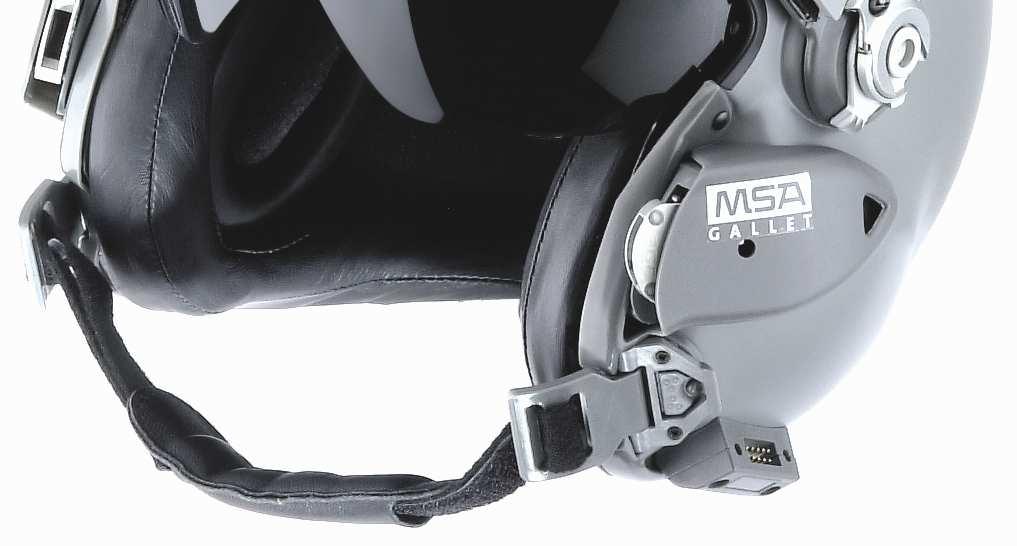
6 1. Chinstrap: Tools: Philips screwdriver. Dismantling duration: 15 seconds. Mounting duration: 30 seconds. The chinstrap is secured to the helmet by means of two screws on the left chinstrap bracket. To remove the chinstrap, unscrew the screws on the left side, then take out the chinstrap levers by holding them by the ends. To reinstall, engage each lever, making sure the chin cup is the right way round (the return part of the strap should be uppermost) and so are the levers. Lock by pressing in the middle of the lever. Tighten the 2 screws. You do not have to remove the chinstrap in order to take off the chin cup. Important: when reinstalling, the screws should be tightened 1/8 of a turn from when the tightening stress increases (screwing into plastic). Screws securing the chinstrap 5

, The neck pad (XS, S and M or L, XL and XXL depending on the helmet size), The")
.")

7 Maintenance manual 2. Inner liner elements: Tools: None. Dismantling duration: 20 seconds. Mounting duration: 45 seconds. There are three inner liner elements: The comfort liner with its interchangeable foam pieces, each supplied in 3 thicknesses (4, 8 and 12 mm thick), The neck pad (XS, S and M or L, XL and XXL depending on the helmet size), The ear cups and their adjustment pads (3 on each side + 2 extra on each side), The comfort liner is adjustable in 4 areas with 3 possible thicknesses (N.B. When replacing the foam pieces, check that they are seated correctly). The neck pad is also supplied in 3 different thicknesses. The liner elements are fixed to the impact cap and shell with hook and loop tape, so no tools are needed. N.B. Be careful not to break the polystyrene core of the neck pad during removal or reinstallation. The audio cables must run between the edge roll and the neck pad (see audio cable section). 6
 and adjusts to fit the shell by means of two fastening pins.")

8 3. Edge roll Tools: None. Dismantling duration: 20 seconds. Mounting duration: 45 seconds.. The edge roll is replaceable. It is attached to the rim by means of press studs (3 on each side) and adjusts to fit the shell by means of two fastening pins. No tools are needed for its removal and reinstallation. When removing the edge roll, it is best to take out the ear cups and the neck pad first. Then detach the 6 press studs and remove the 3 pins. When removing the first pin, it is important to twist the edge roll then slide the pin along its slot. The second pin will then come out easily on its own. To reinstall the edge roll, engage the pins one after the other in the slots, then fasten the press studs. 7

9 4. Inner visor: Tools: None. Removal time: 15 seconds. Reinstallation time: 30 seconds. The inner visor is attached to its rotation system by means of clips. Move the visor to the lowered position. Important: the direction of removal of the inner visor is perpendicular to the 2 rivets of the visor attachments. To reinstall it, check that the control levers of the inner visor are in the lowered position. Engage the visor so that the clips will go into their housings correctly. Clip in by pressing on the ends of the visor. Rotation system in lowered position Reinstallation: Insert the clips into their housings and push to clip the visor in place Removal: Pull the visor at a right angle to the 2 rivets 8
.")


10 5. Outer visor: Tools: 2 mm hexagonal screwdriver, Philips screwdriver. Removal time: 2 minutes. Reinstallation time: 2 minutes. Remove the hard cover (see section 6). Unscrew the 2 small BLACK M2, 2x6 TF POZIDRIV screws at the front. Lower the visor so that you can remove the outer visor guide assembly from the rail. Then pull the left and right guide systems away from the helmet. 9 For reassembly, perform the same operations in reverse. Warning When you are reinstalling the hard cover, check that the pin is correctly positioned in the base. Tighten the STAINLESS STEEL M3X8 TF HC screws on the right and left.


11 6. NVG hard cover: Tools: None Removal time: 10 seconds. Reinstallation time: 30 seconds. Release the side hooks of the hard cover left and right simultaneously and switch the hard cover backward. For reassembly, perform the same operations in reverse. Align cover pins in pinholes located on the helmet. 10 Warning When you are reinstalling the hard cover, check that the pin is correctly positioned in the base.


12 7. Earphones and hygiene parts of the ear cups: Tools: 5.5 mm (box or flat) spanner Dismantling duration: 3 minutes. Mounting duration: 4 minutes. To remove the earphones, take out the ear cups. For each ear cup: Remove the fabric seal. Remove the 2 acoustic foam pieces Pull the earphone cable away for easier access. 11 Unscrew the 2 nuts from the terminals. (Keep the nuts, etc.) Remove the 3 connectors. To reassemble, proceed in the reverse order.
13 8- Oxygen mask receiver: Tools: 2 mm hexagonal screwdriver, Philips screwdriver. Removal time: 2 minutes. Reinstallation time: 2 minutes. - take out the left and right ear cups; - Unscrew the rear countersunk head screw with the black washer inside the shell; - Unscrew two button head screws with their two washers (one black + one star washer each) inside the shell. To reassemble, proceed in the reverse order. Important : during reassemble, the rear countersunk head screw must tighten one-eighth turn as soon as the clamping force increases (tightening in plastic material). button head screws, flat washer and star washer 12 rear countersunk head screw with the black washer
14 GENERAL INFORMATION This section concerns the tests and inspections required to determine the condition of any units withdrawn from service. Dispose of any defective parts. All defective parts should be disposed of and replaced with new parts from MSA only. All tests should be carried out on clean parts (see section on cleaning). Inspection, testing and maintenance table: Basic checks* Pre-flight Visors cleanliness and operation yes Presence and secure attachment of comfort elements yes (comfort liner, neck pad, edge roll) Condition of chinstrap and attachment points, operation of buckle yes Communication system test yes Attachment of hard cover yes Shell and hard cover (no cracks, no dents, aramid and carbon yes not visible, screws and inserts in their housings) General condition of helmet yes Periodic checks* Frequency Shell condition: particularly adhesion of chinstrap mounts, slight impacts 3 months due to normal use Condition of impact cap and rim: in particular adhesion of impact cap to rim 3 months Attachment of impact cap to shell 3 months Secure attachment and operation of visors on their bases, communication 3 months system, cable protector Condition and operation of visors and their attachment system 3 months Condition of comfort liner pads 3 months Condition of inner liner elements and ear cups 3 months Condition of chinstrap and fastening buckle 3 months Operation of chinstrap locking system 3 months Operation of communication system (with inspection of cable condition) 3 months Check that all screws are tight 3 months Check the play of moving sub-assemblies during operation 3 months Cleaning (in accordance with the instructions given in the user manual) 3 months Recommended replacement of main parts* Frequency Inner visor 5 years Outer visor 5 years Edge roll 2 years Comfort liner and neck pad 2 years Chinstrap attachment assembly 2 years Chinstrap 2 years Comfort ear seals 2 years LH 250 chinstrap assembly 2 years Impact cap 15 years Shell 15 years *: based on normal use of 200 hours per year and depending on the condition of the part. 13
15 MANDATORY INSPECTIONS AND REPLACEMENT CRITERIA This section explains the mandatory action to be taken and the inspections necessary when a helmet has suffered an impact OR when maintenance reveals damage caused by an impact. See criteria appendices. The mandatory action and necessary inspections are explained in the table below. ACTION TO BE TAKEN The helmet shell is designed to protect against a single impact. The integrity of the shell is considered to have been compromised after an impact. The shell of a helmet that has suffered an impact must be destroyed and replaced. Mandatory inspection Where damage caused by the impact is found. The helmet must be inspected to check for Dents, cracking or deformation of the composite fibres in the shell or hard cover; Damage to the composite shell consisting of composite fibres that have been cut or shredded; Removal of the outer coating leading to damage to the gel coat layer and exposure of the composite fibres; Movement of the impact cap; Damage to the visors and the visor movement mechanisms; Damage to the chinstraps at the chinstrap anchor points and the fastening buckle; The inspection must be recorded on the equipment monitoring sheet. If the inspection confirms an impact, the shell and the impact cap must be replaced. Condition Impact: IMPACT CONFIRMED Suspected impact: Mandatory inspections if an impact is suspected 14 User and maintenance workshop All helmet users and maintenance units are responsible for reporting known or suspected impacts and damage to helmets. MSA will not be held responsible for failure to remove from service a shell that has been damaged or has suffered an impact. Only MSA distributor is authorized to remove the impact cap. In case of doubt about the integrity of the impact cap or the shell, contact your MSA distributor.
16 APPENDICES: Replacement criteria - LH 250 PM and GM shell and fittings Sub-elements - Defects Criteria - Action Aramid fibres Cracks and/or damaged* Replace Shell scratches Aramid fibres not damaged* Nothing to report Impacts Height of fall > 1 m Replace Height of fall < 1 m Nothing to report Riveting Defective Replace Rail Attachment Coming apart Replace Breakage Defective Replace Wear Defective Replace Riveting Defective Replace Chinstrap mount Attachment Coming apart Replace Breakage Defective Replace Wear Defective Replace Edge seals Attachment Coming apart Rebond with glue. 15
 do not require replacement of the shell.")


17 Cosmetic defects (paint scratches, etc.) do not require replacement of the shell. Paint scratch Scratch to paint and gel coat but no damage to aramid or carbon. Defect where the aramid and/or carbon are showing The appearance of aramid and/or carbon filaments means Deep scratch affecting the aramid (yellow) or carbon (black) in the shell. 16 Hole following an impact revealing the aramid (yellow) or carbon (black) in the shell.


18 Cracks with or without replacement of the shell If a helmet has one or more paint cracks on the outside and white marks (delamination of the aramid) on the inside, the shell must be replaced. Impacts Warning: cracked paint can signal an impact or that the shell has been tightly squeezed; in this case the impact cap must be removed to check the condition of the aramid inside the shell. If a helmet has one or more traces of impacts on the outside and white marks (delamination of the aramid) on the inside, the shell must be replaced. Specific traces of an impact inside the shell: concentric white lines matching the cracks on the outside. 17 Paint Gelcoat Resin Carbon fibre The appearance of carbon filaments in the area where the visor mechanism is located means that the shell must be replaced.


19 Complete PM and GM aviation impact caps The impact cap/rim assembly must be replaced in the following cases - deformed impact cap, - impact cap unstuck from its rim, - rim showing white marks. Sub-elements Defects Criteria - Action Rim Impact cap Inner liner Press stud White mark on the carbon Part close to leather + rayon** Nothing to report Breakage Defective Replace Weld Crack Replace Attachment Coming apart Replace Deformation Defective Replace Breakage Defective Replace Attachment Coming apart Replace Crimping Excessive play or missing Replace part near leather + rayon 18 Examples of white marks on the carbon rim of the impact cap.
20 PM and GM inner visor assembly Zones on inner visor: PM and GM outer visor assembly Zones on outer visor: 19
21 Zone Defects Criteria Action Spots of paint Ø 0.1 mm Quantity > 3 Replace part Spots of paint Ø > 0.1 mm Quantity = 0 Replace part Zone 1 Scratches: length < 5 mm, Quantity > 8 Replace part depth < 0.05 mm Spots of paint 0.1 mm < Ø < 0.2 mm Quantity > 5 Replace part or Black spots 0.1 mm < Ø < 0.2 mm Quantity = 2 Replace part Zones 2 and 3 or Scratches: length < 5 mm; Quantity > Replace part depth < 0.05 mm 16 Zone 4 All None Sub-elements Defects Criteria Action Coming apart Minor Nothing to report Velcro hooks Coming apart Major Replace part Lateral interfaces Riveting Excessive play or missing Replace part Lateral interface Breakage Defective Replace part Visor inserts Coming loose Defective Replace part Spring stuck Operation of hooks Outer visor guide or lost Replace sub-assembly Slider Defective Replace sub-assembly Inner visor rotation tests It must be possible to rotate the visor using either of the knobs with one hand (thumb/index finger). N.B.: The two screws holding in place the inner visor controls should be tightened 1/8 turn from when the tightening stress increases, with the 2 mm hex screwdriver. 20 Outer visor locking tests Starting from the raised position, the visor is locked and unlocked in the lowered positions
22 Chinstrap assembly Sub-elements Defects Criteria Action Locking clip Play Free Replace chinstrap assembly or locking clip Replace chinstrap Chinstrap lever Crack Defective assembly or chinstrap or scale attachment Strap Stitching Defective Replace chinstrap assembly or strap Screw Missing Defective Replace chinstrap assembly or screw Strap Wear Defective Replace chinstrap assembly or strap Keeper Wear Defective Replace chinstrap assembly or keeper 21
LH 050 / 150 /250 FLIGHT HELMET
 LH 050 / 150 /250 Flight Helmet Instruction Manual Page 1 of 14 CGF GALLET LH 050 / 150 /250 FLIGHT HELMET Instruction Manual ENGLISH Compiled into PDF Format by Flight Helmets Australia Specialising in
The Safety Company LH 050/150/250. [Helicopter Flight Helmet] English. REF : 074 xxx* REF : 071 xxx* REF : 072 xxx*
![The Safety Company LH 050/150/250. [Helicopter Flight Helmet] English. REF : 074 xxx* REF : 071 xxx* REF : 072 xxx*](/thumbs/84/89464491.jpg "The Safety Company LH 050/150/250. [Helicopter Flight Helmet] English. REF : 074 xxx* REF : 071 xxx* REF : 072 xxx*") LH 050/150/250 [Helicopter Flight Helmet] English REF : 074 xxx* REF : 071 xxx* REF : 072 xxx* WARNING Thank you for your confidence in MSA GALLET products. Please read the instruction manual carefully.
LH 050/150/250 [Helicopter Flight Helmet] English REF : 074 xxx* REF : 071 xxx* REF : 072 xxx* WARNING Thank you for your confidence in MSA GALLET products. Please read the instruction manual carefully.
MSA GALLET B.P. 90 Z.I. sud F Châtillon-sur-Chalaronne Tel.+33 (4) Fax.+33 (4)
 Fax.+33 (4)") MSA GALLET B.P. 90 Z.I. sud F-01400 Châtillon-sur-Chalaronne Tel.+33 (4) 74 55 01 55 Fax.+33 (4) 74 55 24 80 Email : message@msa-gallet.fr www.msa-gallet.fr The information specified in this document is
MSA GALLET B.P. 90 Z.I. sud F-01400 Châtillon-sur-Chalaronne Tel.+33 (4) 74 55 01 55 Fax.+33 (4) 74 55 24 80 Email : message@msa-gallet.fr www.msa-gallet.fr The information specified in this document is
AS/NZS 1801 USE AND CARE BOOKLET OCCUPATIONAL PROTECTIVE HELMET
 AS/NZS 1801 USE AND CARE BOOKLET OCCUPATIONAL PROTECTIVE HELMET 2 EN DANGER! intended use of this helmet involves activities that are extremely dangerous. FAILURE TO HEED AND FOLLOW THESE INSTRUCTIONS
8MAY15 US RACK, Inc Falcon Drive, Madera, CA
 8MAY15 US RACK, Inc. - 2850 Falcon Drive, Madera, CA 93637-559-661-3050 INSTRUCTIONS for Bedrail-mounted MOTORCYCLE RACK, Model 2001-4TRA WARNING: Do NOT attempt to install or use this rack without following
Vanguard and Vanguard II Helmets
 Vanguard and Vanguard II Helmets WARNINGS, CAUTIONS, AND INSTRUCTIONS THIS BOOKLET MUST BE CAREFULLY READ BY ALL INDIVIDUALS WHO WEAR OR MAINTAIN THIS HELMET, INCLUDING THOSE WHO HAVE ANY RESPONSI- BILITY
EZee Glider Manual. Tools needed for Assembly: Wrench (included) Philips Screwdriver (not included) Assembly Instructions
 Philips Screwdriver (not included) Assembly Instructions") EZee Glider Manual Congratulations on your purchase of the EZee Glider! Your glider is designed for years of nearly carefree use by your child. These instructions include how to set up your glider and
EZee Glider Manual Congratulations on your purchase of the EZee Glider! Your glider is designed for years of nearly carefree use by your child. These instructions include how to set up your glider and
MSA Cairns FIRE HELMET PRODUCT SPECIFICATION
 MSA Cairns FIRE HELMET PRODUCT SPECIFICATION PRODUCT TYPE: Structural Firefighting Helmet PRODUCT MODEL(S): PURPOSE: To supply a uniform, standard product specification for a thermoplastic structural fire
BMW Motorrad. Installation Instructions. BMW Motorrad Communications System for Schuberth C3
 BMW Motorrad Installation Instructions BMW Motorrad Communications System for Schuberth C3 Order No. 01 29 2 219 831 BMW Motorrad 05/2011 Be sure to read these instructions carefully and completely before
SAFETY RULES WARNING: READ THESE SAFETY RULES & OPERATORS MANUAL BEFORE HANDLING YOUR FIREARM
 SAFETY RULES WARNING: READ THESE SAFETY RULES & OPERATORS MANUAL BEFORE HANDLING YOUR FIREARM Never point a firearm at anyone and always keep the muzzle pointed in a safe direction. Always treat all firearms
E-trike Li Assembly Guide
 PREPARATION 1. Read this assembly manual BEFORE commencing assembly. 2. Carefully remove all the components and packaged hardware from the shipping boxes. 3. Unpack the contents of the large double box
SS650 HELMET USER MANUAL
 SS650 HELMET USER MANUAL READ BEFORE USING YOUR SPEED AND STRENGTH HELMET Congratulations on the purchase of your new Speed and Strength motorcycle helmet. At Speed and Strength, we take great pride in
MSA Cairns FIRE HELMET PRODUCT SPECIFICATION
 MSA Cairns FIRE HELMET PRODUCT SPECIFICATION PRODUCT TYPE: Structural and Urban Search and Rescue Firefighting Helmet PRODUCT MODEL(S): PURPOSE: To supply a uniform, standard product specification for
GRAVITY BIKE RACK ASSEMBLY & OPERATING INSTRUCTIONS
 GRAVITY BIKE RACK 94479 ASSEMBLY & OPERATING INSTRUCTIONS Due to continuing improvement, actual product may differ slightly from the product described herein. 3491 Mission Oaks Blvd., Camarillo, CA 93011
Toronto District School Board
 Toronto District School Board Title: Operational Procedure PR600 USE OF HEAD PROTECTION DURING SKATING, SKIING AND SNOWBOARDING ACTIVITIES Adopted: January 19, 2010 Revised: Authorization: Executive Committee
NOTES BEFORE USE BE SURE TO READ THIS MANUAL BEFORE USING THE HELMET. KEEP THE MANUAL IN A SAFE PLACE FOR FUTURE REFERENCE.
 NOTES BEFORE USE BE SURE TO READ THIS MANUAL BEFORE USING THE HELMET. KEEP THE MANUAL IN A SAFE PLACE FOR FUTURE REFERENCE. 01 Chinstraps Chinstraps play an important role under an accident, preventing
HELMET OPERATOR S MANUAL OPS-CORE REV. C
 HELMET OPERATOR S MANUAL OPS-CORE 2014 06-05-161 REV. C FOR SENTRY HELMETS HELMET VERSION SENTRY HELMET This manual is specific to the Sentry Helmet. SENTRY HELMET INCLUDES: (2) SIDE PADS, (2) 1/2 TOP
HELMET OPERATOR S MANUAL OPS-CORE REV. B
 HELMET OPERATOR S MANUAL OPS-CORE 2016 06-05-160 REV. B FOR FAST BALLISTIC AND CARBON HELMETS HELMET VERSIONS FAST HELMETS This manual is specific to the following helmet models: FAST Ballistic High Cut,
Mini Glider Manual. Your Glider comes partially assembled. The front wheel and the handlebars require assembly.
 Mini Glider Manual Congratulations on your purchase of the Mini Glider! Your glider is designed for years of nearly carefree use by your child. These instructions include how to set up your glider and
Cleaning rod: spring steel, stainless steel or carbon fibre cleaning rod - only use a one-piece rod. Avoid using snakes.
 Telemark Biathlon Where performance and precision come together http://telemarkbiathlon.com Rifle Cleaning Date : July 19, 2013 Anschutz Rifle Manual - Click Here Izhmash 7-3 Rifle Manual - still looking
DISASSEMBLING & REASSEMBLING CARTRIDGE INSTALLING SEATPOST ON BIKE
 INTRODUCTION BILL OF MATERIALS SPECIFICATIONS & TOOLS PROCEDURES DISASSEMBLING & REASSEMBLING CARTRIDGE INSTALLING SEATPOST ON BIKE OPERATION OF SEATPOST GIANT LIMITED WARRANTY 1 INTRODUCTION Congratulations
Pre-Paint>Fuselage>Empennage>Fit vertical tail fin. Objectives of this task: Materials and equipment required: Fit the spar extender
 Pre-Paint>Fuselage>Empennage>Fit vertical tail fin Objectives of this task: To fit the vertical tail fin to the fuselage, including fitting the static probe, static tube, optional strobe light wiring and
Extreme Sport Helmets
 Page #1/14 Extreme Sport Helmets and maintenance guide 1 Page #2/14 Icaro 2000 congratulates you on your purchase of this new extreme sports helmet. The principal purpose of our helmets, safety, has been
SOTR Special Operations Tactical Respirator
 SOTR Special Operations Tactical Respirator OPERATOR S MANUAL FOR INDIVIDUAL RESPIRATORY PROTECTION OPS-CORE 2018 OMM G055-1000 REV. B INTRODUCTION ABOUT YOUR SOTR The Ops-Core Special Operations Tactical
VERSA BIKE RACK INSTRUCTIONS
 VERSA BIKE RACK INSTRUCTIONS Models #8, 8 Important This rack is designed for use with a or. receiver hitch. The rack is designed to hold a maximum of two bicycles. Do not use it for anything other than
How to replace your VIPER Visor
 How to replace your VIPER Visor groove Visor Disassembly Open it slightly to let crystal point stay in the red part. Pull the groove,use the other hand pull it downwards along the direction of the up arrow.
Santa Fe Cycles Assembly Guide Introduction
 Santa Fe Cycles Assembly Guide Introduction Congratulations on your purchase of your new Santa Fe bicycle. You have purchased a bicycle that has many features and qualities. Please take a few minutes and
Product Information News
 Product Information News MMR SECOND STAGE REGULATOR VALVE CORE MSA has changed its recommended rebuilding of the MMR Second Stage Regulator s bypass sleeve assembly during the annual inspection. Based
Installation Manual. Version 12-10
 Installation Manual The products and parts shown herein are to be installed and used adjusted in accordance with these instructions. Any deviation by the buyer, installer, or user from these instructions
DM-MARD (English) Dealer's Manual. ROAD MTB Trekking. City Touring/ Comfort Bike REAR DERAILLEUR XTR RD-M9100 RD-M9120
 Dealer's Manual. ROAD MTB Trekking. City Touring/ Comfort Bike REAR DERAILLEUR XTR RD-M9100 RD-M9120") (English) DM-MARD001-00 Dealer's Manual ROAD MTB Trekking City Touring/ Comfort Bike URBAN SPORT E-BIKE REAR DERAILLEUR XTR RD-M9100 RD-M9120 CONTENTS CONTENTS...2 IMPORTANT NOTICE...3 TO ENSURE SAFETY...4
(English) DM-MARD001-00 Dealer's Manual ROAD MTB Trekking City Touring/ Comfort Bike URBAN SPORT E-BIKE REAR DERAILLEUR XTR RD-M9100 RD-M9120 CONTENTS CONTENTS...2 IMPORTANT NOTICE...3 TO ENSURE SAFETY...4
Assembly, Fitting, Care & Maintenance
 Assembly, Fitting, Care & Maintenance Assembly 1.1 Remove All Parts and Tools from Packaging 1.2 Part and Tools required for assembly 1.3 Check Foot & Leg Assembly 1.4 Adjust Upper-Leg-Support (ULS) Height
OWNERS MANUAL. Model Shown with optional Primary Mooring Cleats. Portable Mooring System SAFETY OPERATION MAINTENANCE PARTS
 OWNERS MANUAL Model 2400 Shown with optional Primary Mooring Cleats. Portable Mooring System SAFETY OPERATION MAINTENANCE PARTS CAUTION: Before using your new Pier Tender, read rules for Safety, Operation,
7130 Lancer Rear Drive Magnetic Commercial Indoor Cycling Bike
 7130 Lancer Rear Drive Magnetic Commercial Indoor Cycling Bike Owner s Manual Made in Taiwan INDEX IMPORTANT SAFETY INFORMATION... 1 EXPLODED DRAWING... 2 PARTS LIST... 3 ASSEMBLY INSTRUCTION... 4-9 USER
Pectoral Machine. User manual E S S E N T I A L S T R E N G T H
 E L E M E N T and the cable E S S E N T I A L S T R E N G T H User manual 1 and the cable and The identification plate of and manufacturer, affixed on the back panel of the weight stack, gives the following
SS1700 HELMET USER MANUAL
 SS1700 HELMET USER MANUAL Congratulations on the purchase of your new Speed and Strength MOTORCYCLE helmet. At Speed and Strength, we take GREAT pride in our gear and we know that it is the best possible
2019 MADONE ASSEMBLY MANUAL
 2019 MADONE ASSEMBLY MANUAL 2019 MADONE Rim brakes and Di2 drivetrain Rim brakes and mechanical drivetrain Disc brakes and Di2 drivetrain Disc brakes and mechanical drivetrain TABLE OF CONTENTS Common
Cantilever Brake. Dealer's Manual. ROAD MTB Trekking. City Touring/ Comfort Bike
 (English) DM-RCBR001-00 Dealer's Manual ROAD MTB Trekking City Touring/ Comfort Bike URBAN SPORT E-BIKE Cantilever Brake BR-CX70 BR-CX50 BL-4700 BL-4600 BL-R780 BL-R3000 ST-7900 ST-6700 ST-5700 ST-4600
600 / 600FC OWNER'S MANUAL
 PROGRESSION 600 / 600FC OWNER'S MANUAL Issue 2 / Version E - Dec. 10, 1997 Copyright 1997 GAMMA Sports - All Rights Reserved PROGRESSION 600 / 600FC OWNER'S MANUAL TABLE OF CONTENTS PAGE 1... WARRANTY
INTRODUCTION BILL OF MATERIALS SPECIFICATIONS & TOOLS PROCEDURES OPERATION OF SEATPOST GIANT LIMITED WARRANTY
 INTRODUCTION BILL OF MATERIALS SPECIFICATIONS & TOOLS PROCEDURES OPERATION OF SEATPOST GIANT LIMITED WARRANTY 1 INTRODUCTION Congratulations on the purchase of your new GIANT CONTACT SWITCH seatpost. This
Congratulations on your purchase of a JC Series Performer trike! The Performer JC Series is designed for everything from touring to commuting and
 Congratulations on your purchase of a JC Series Performer trike! The Performer JC Series is designed for everything from touring to commuting and shopping in the city. The JC Series frames are made of
Important Note: Tighten lock nuts so the support tubes still swing freely see figure 2. There must be 1 2 threads of bolt past end of lock nuts.
 Kit Contents: DESCRIPTION QTY. DESCRIPTION QTY. 2 Shank Assembly 1 Support Tube Assembly 1 Side Tube - Short 2 1-1/4 Shank 1 Center Tube - Long 1 3/8-16 x 2.0 Carriage Bolt 2 5/16-18 x 2.25 Carriage Bolt
GM-121: Container End Lock Anchor Wand Page 1 WINSAFE CORP. GM 121 CONTAINER END LOCK ANCHOR WAND OPERATING INSTRUCTIONS AND MAINTENANCE
 GM-121: Container End Lock Anchor Wand Page 1 WINSAFE CORP. GM 121 CONTAINER END LOCK ANCHOR WAND OPERATING INSTRUCTIONS AND MAINTENANCE US Patent No. 6834745 This equipment conforms to 0321 EN795:1996
Shifting Lever. RAPIDFIRE Plus 11-speed
 (English) DM-SL0005-04 Shifting Lever Dealer's Manual RAPIDFIRE Plus 11-speed MTB XTR SL-M9000 DEORE XT SL-M8000 CONTENTS IMPORTANT NOTICE... 3 TO ENSURE SAFETY... 4 LIST OF TOOLS TO BE USED... 7 INSTALLATION...
Tactical Ballistic Helmet II (TBH II )
") Care and Use Instructions Tactical Ballistic Helmet II (TBH II ) Mission Configurable (MC) TBH II MC TBH II HC-MC TBH II HST-MC 2013 Gentex Corporation When you replace components or install additional
Care and Use Instructions Tactical Ballistic Helmet II (TBH II ) Mission Configurable (MC) TBH II MC TBH II HC-MC TBH II HST-MC 2013 Gentex Corporation When you replace components or install additional
DM-RD (English) Dealer s Manual. ROAD Rear Derailleur RD-9000 RD-6800 RD-5800 RD-4700
 Dealer s Manual. ROAD Rear Derailleur RD-9000 RD-6800 RD-5800 RD-4700") (English) DM-RD0003-09 ROAD Rear Derailleur Dealer s Manual RD-9000 RD-6800 RD-5800 RD-4700 CONTENTS IMPORTANT NOTICE...3 TO ENSURE SAFETY...4 LIST OF TOOLS TO BE USED...6 INSTALLATION...8 Chain length...
(English) DM-RD0003-09 ROAD Rear Derailleur Dealer s Manual RD-9000 RD-6800 RD-5800 RD-4700 CONTENTS IMPORTANT NOTICE...3 TO ENSURE SAFETY...4 LIST OF TOOLS TO BE USED...6 INSTALLATION...8 Chain length...
CONTENTS: VENTILATION P 09 VISOR P J 12 F1 - K1
 CONTENTS: VENTILATION P 09 VISOR P 10-11 VENTILATION P 09 01 J 12 F1 - K1 BACK SPOILER P 12 SPARE PARTS P 06 TEAR-OFF LENS P 13 HANS DEVICE P 12 D-RING P 07-08 J 12 F1 - K1 02 WARNINGS Thank you for choosing
P Pod Postural Support System
 P Pod Postural Support System APP-1000XS APP-2000S APP-3000M APP-4000L APP-5000XL www.inspiredbydrive.com WARNING! Read ALL instructions before using this product! IMPORTANT SAFETY RULES Determine, with
READ ALL INSTRUCTIONS AND WARNINGS BEFORE USING THIS PRODUCT.
 Drywall Stills DS1830 Max Weight Capacity 225 Lb READ ALL INSTRUCTIONS AND WARNINGS BEFORE USING THIS PRODUCT. This manual provides important information on proper operation & maintenance. Every effort
POWER ASSISTED BICYCLES OWNERS MANUAL
 POWER ASSISTED BICYCLES OWNERS MANUAL WE HAVE INCLUDED A BICYCLE OWNER S MANUAL WHICH YOU SHOULD REFER TO FOR ALL GENERAL CYCLE MAINTENANCE. CONTENTS Page. 3 Unpacking. Page. 3-4 Easy steps to get started.
Operating Manual. 3S-R AirElite Full Face Mask Advantage AirElite Full Face Mask Advantage 4000 AirElite Full Face Mask. AirElite - Full Face Masks
 Operating Manual 3S-R AirElite Full Face Mask Advantage AirElite Full Face Mask Advantage 4000 AirElite Full Face Mask AirElite - Full Face Masks Order No.: 10065505/05 MSA AUER GmbH D-12059 Berlin Thiemannstraße
Installation instructions for the Yepp Maxi Easyfit
 Installation instructions for the Yepp Maxi Easyfit The Yepp Maxi Easyfit is suitable for: - fitting to an Easyfit luggage carrier* (fig 1A) or - fitting in combination with the Yepp Maxi Easyfit carrier
SERIES 2 RAMP OWNER S MANUAL TOOLS REQUIRED: BEFORE YOU BEGIN... Read and understand these instructions before beginning a ramp setup.
 SERIES 2 RAMP OWNER S MANUAL BEFORE YOU BEGIN... Read and understand these instructions before beginning a ramp setup. Use caution and care for your back when lifting, pushing, pulling, folding or unfolding
ExtendAire TM II. Intermediate Pressure Accessory Kit USER INSTRUCTIONS
 ExtendAire TM II Intermediate Pressure Accessory Kit USER INSTRUCTIONS THIS MANUAL MUST BE CAREFULLY READ AND FOLLOWED BY ALL PERSONS WHO HAVE OR WILL HAVE THE RESPONSIBILITY FOR USING OR SERVICING THIS
Bontrager Adult and Kids Bicycle Helmet Owner s Manual ENGLISH
 Bontrager Adult and Kids Bicycle Helmet Owner s Manual ENGLISH 538209.3 CONGRATULATIONS Thank you for choosing a Bontrager bicycle helmet. This helmet is constructed to meet the highest standards for performance
SANTANA STOWAWAY TANDEM WITH AIRLINER SAFECASE AND FTS FOAM TRAY SYSTEM ASSEMBLY AND DISASSEMBLY
 SANTANA STOWAWAY TANDEM WITH AIRLINER SAFECASE AND FTS FOAM TRAY SYSTEM ASSEMBLY AND DISASSEMBLY Congratulations! You are now the proud owner of the world s most travel-ready, performance tandem. The following
FIRST TEAM SPORTS, INC Storm Portable Series Assembly Instructions
 FIRST TEAM SPORTS, INC Storm Portable Series Assembly Instructions WARNING! WARNING! WARNING! THIS BASKETBALL SYSTEM IS SPRING LOADED AND SHIPPED UNDER TENSION. ATTEMPTING TO ASSEMBLE OR DISASSEMBLE ANY
HOME ASSEMBLY INSTRUCTIONS
 HOME ASSEMBLY INSTRUCTIONS This Papillionaire Bicycle now belongs to you. It will take you to work, wait patiently outside your local cafe, and carry your groceries home. This is the start of your long-term
PART NUMBER: E361SXA200 DESCRIPTION: KAYAK CARRIER
 A KIT CONTENTS: : Plug 16x Long Carriage Bolt 4x Hex Key 4x Button Head Screw 4x Pad Strap BASE Over-Molded Wrench 1x SnapAround 4x 1/5 : Important Notes: Minimum crossbar spread of 24". If spread is less
Falcon 3 145, 170, 195 and Tandem Owner / Service Manual
 Falcon 3 145, 170, 195 and Tandem Owner / Service Manual January 2007 - Second Edition Removing The Sail From The Airframe And Short Packing The Glider Many maintenance and repair procedures will require
2019 MADONE ASSEMBLY MANUAL
 2019 MADONE ASSEMBLY MANUAL 2019 MADONE Rim brakes and Di2 drivetrain Disc brakes and Di2 drivetrain Rim brakes and mechanical drivetrain Disc brakes and mechanical drivetrain TABLE OF CONTENTS Common
LITERIDER 2&3 IMPORTANT WARNING. 2Bike (1x) Bolt (1x) Nut (1x) Small Hex Wrench (1x)
 Bolt (1x) Nut (1x) Small Hex Wrench (1x)") LITERIDER 2&3 3 Bike (1x) Bolt (1x) Flat Washer (2x) Nut (1x) Large Hex Wrench (1x) 2Bike (1x) wrench (1x) Small Hex Wrench (1x) keys (2x) Long Strap (1x) 2-Zip Strips (6x) 3-Zip Strips (9x) Wheel strap
LITERIDER 2&3 3 Bike (1x) Bolt (1x) Flat Washer (2x) Nut (1x) Large Hex Wrench (1x) 2Bike (1x) wrench (1x) Small Hex Wrench (1x) keys (2x) Long Strap (1x) 2-Zip Strips (6x) 3-Zip Strips (9x) Wheel strap
TAL 803 (L) Rev. 4 MSA 2008 Prnt. Spec (EE) Mat Doc
 Rev. 4 MSA 2008 Prnt. Spec (EE) Mat Doc") TAL 803 (L) Rev. 4 MSA 2008 Prnt. Spec. 10000005389(EE) Mat. 10063328 Doc. 10063328 WARNING SUMMARY This warning summary contains general safety warnings and hazardous materials warnings that must be
TAL 803 (L) Rev. 4 MSA 2008 Prnt. Spec. 10000005389(EE) Mat. 10063328 Doc. 10063328 WARNING SUMMARY This warning summary contains general safety warnings and hazardous materials warnings that must be
E-118 Assembly Guide
 E-118 Assembly Guide Table of Contents Overview of the assembly.... 2 1. Fork installation.... 3-4 2. Cable housing installation.... 5 3. Handlebar installation... 6 4. Front brake installation.... 7-8
222 Schwinn Recumbent Exercise Bike Parts List Full Size Hardware Chart Product Illustration Assembly Instructions
 222 Schwinn Recumbent Exercise Bike Parts List Full Size Hardware Chart Product Illustration Assembly Instructions FITNESS SAFEGUARDS AND WARNINGS Before starting any exercise program, consult with your
Front derailleur. Dealer's Manual FD-M9000 FD-M9020 FD-M9025 FD-M8000 FD-M8020 FD-M8025 FD-M612 FD-M617 FD-M618 FD-M672 FD-M677
 (English) DM-FD0003-05 Front derailleur Dealer's Manual FD-M9000 FD-M9020 FD-M9025 FD-M8000 FD-M8020 FD-M8025 FD-M612 FD-M617 FD-M618 FD-M672 FD-M677 CONTENTS IMPORTANT NOTICE... 4 TO ENSURE SAFETY...
Parts: Included in the parts box: Inner Rear Tire Tray. Inner Front Tire Tray. Trail Doc Clamp. Pivot Assembly. Trail Doc Post.
 NV 2.0 2 Parts: Outer Front Tire Tray Inner Front Tire Tray Outer Rear Tire Tray Inner Rear Tire Tray Pivot Assembly Trail Doc Clamp Trail Doc Post Included in the parts box: 6mm Allen Wrench M6 Lock Washer
GM-120: Container Top Lock Anchor Wand Page 1 WINSAFE CORP. GM 120 CONTAINER TOP LOCK ANCHOR WAND OPERATING INSTRUCTIONS AND MAINTENANCE
 GM-120: Container Top Lock Anchor Wand Page 1 WINSAFE CORP. GM 120 CONTAINER TOP LOCK ANCHOR WAND OPERATING INSTRUCTIONS AND MAINTENANCE US Patent No. 6834745 This equipment conforms to 0321 EN795:1996
Universal Elevator Mount Owners Manual Customer Service Center N53 W24700 South Corporate Circle Sussex, WI U.S.A.
 REQUIRED TOOLS AND MATERIALS: 2 Capable Adults Carpenter s Level 15 Tape Measure Pencil Universal Elevator Mount Owners Manual Customer Service Center N53 W2400 South Corporate Circle Sussex, WI 530 U.S.A.
WINSAFE CORP. OPERATING AND MAINTENANCE INSTRUCTIONS GM184 TOP ACCESS END LOCK ANCHOR WAND
 WINSAFE CORP. OPERATING AND MAINTENANCE INSTRUCTIONS GM184 TOP ACCESS END LOCK ANCHOR WAND For more information on this innovative product line manufactured by Winsafe Corp., please contact: G. D. MacKay
Combination Breathing Apparatus
 and Combination Breathing Apparatus ULTRAVUE FACEPIECE TAL 502 (L) Rev. 0 MSA 2005 Prnt. Spec. 10000005389 (I) Mat. 10064385 Doc. 10064385 ULTRAVUE FACEPIECE COMPONENTS Item Part No. Description 800509
comfort without compromising on performance and to fit your various needs on touring,
 Congratulations on your purchase of Goal-26X. Goal-26X is made to enhance comfort without compromising on performance and to fit your various needs on touring, shopping and communicating. Let s have fun
Drawn up by: / RK Revision: 01 Reviewed: Page: 1 of 15 HI-SR 200 USA. Operating instruction APR SR 200 full face mask
 Page: 1 of 15 Operating instruction APR SR 200 full face mask Page: 2 of 15 General information The SR 200 full face mask can be used in two configurations: Together with filters/cartridges from the Sundström
Front derailleur. Dealer's Manual SORA FD-R3000 FD-R3030 CLARIS FD-R2000 FD-R2030. ROAD MTB Trekking. City Touring/ Comfort Bike DM-RBFD001-01
 (English) DM-RBFD001-01 Dealer's Manual ROAD MTB Trekking City Touring/ Comfort Bike URBAN SPORT E-BIKE Front derailleur SORA FD-R3000 FD-R3030 CLARIS FD-R2000 FD-R2030 CONTENTS IMPORTANT NOTICE... 3 TO
Quick Start Guide. HANS Device
 Quick Start Guide HANS Device 2018 Pg. 2 The HANS Device Quick Start Guide Welcome - you re ready to use the same technology that protects the world s top racers. Follow these steps to get started. Install
Front derailleur. Dealer's Manual DURA-ACE FD-R9100 ULTEGRA FD-R FD ROAD MTB Trekking. City Touring/ Comfort Bike DM-RAFD001-03
 (English) DM-RAFD001-03 Dealer's Manual ROAD MTB Trekking City Touring/ Comfort Bike URBAN SPORT E-BIKE Front derailleur DURA-ACE FD-R9100 ULTEGRA FD-R8000 105 FD-5801 Procedures for cable tension adjustment
Contents. Stainless Steel Side Block. 1.1 Separating the Side Block. Stainless Steel Side Block Reassembly of. Assembly from the Helmet Shell
 Separating the Side Block Assembly from the Helmet Shell Contents SSB-1 SSB-3 SSB-5 SSB-5 SSB-7 1.1 Separating the Side Block Assembly from the Helmet Shell 1.2 Side Block Assembly Replacement 1.3 Defogger
AN AUTHORIZED SUPPLIER OF HELMETS TO THE NFL PLAYER S MANUAL VISIT: XENITH.COM CALL:
 AN AUTHORIZED SUPPLIER PLAYER S MANUAL VISIT: XENITH.COM CALL: 866.888.2322 FITTING INSTRUCTIONS AN AUTHORIZED SUPPLIER INTRODUCTION A PROPER FIT IS INTEGRAL TO A HELMET S PERFORMANCE. PLEASE READ THE
CLIMBING Pads. Straps Gaffs Spikes Hardware
 CLIMBING Pads Straps Gaffs Spikes Hardware Quick Change Aluminum Climbers CTB Tree and Pole Climbing Kit Kit with straps and L pads Patented design give these climbers strength, durability and style Utilizes
#59114 Rola 2-Bike Rack Carrier (Shown Assembled) (A) (C) (B)
 (A) (C) (B)") Use for Parts: #59114 Rola -Bike Rack System #59115 Rola 1-Bike Add-On TOOLS REQUIRED 10mm or 13/3 Socket & Wrench #59114 Rola -Bike Rack Carrier (Shown Assembled) Tray Attachment Hardware: (3) Plastic
Use for Parts: #59114 Rola -Bike Rack System #59115 Rola 1-Bike Add-On TOOLS REQUIRED 10mm or 13/3 Socket & Wrench #59114 Rola -Bike Rack Carrier (Shown Assembled) Tray Attachment Hardware: (3) Plastic
USER S MANUAL QUESTIONS? CAUTION. Model No. FMEX Serial No. Write the serial number in the space above for reference. Serial Number Decal
 Model No. FMEX81110.0 Serial No. Write the serial number in the space above for reference. USER S MANUAL Serial Number Decal QUESTIONS? If you have questions, or if parts are damaged or missing, please
BICYCLE ASSEMBLY INSTRUCTIONS. dutchcycles.com.au. Distribution Centre
 BICYCLE ASSEMBLY INSTRUCTIONS dutchcycles.com.au Distribution Centre Shed 68, 400-422 Somerville Road, Tottenham, VIC 3012 email: service@dutchcycles.com.au BICYCLE COMPONENTS KEY INTRODUCTION CONGRATULATIONS
Protective helmet for structural fire fighting certified to AS/NZS 4067: A1:2014. HEROS-titan AS. User Information (EN)
") Protective helmet for structural fire fighting certified to AS/NZS 4067:2012 + A1:2014. HEROS-titan AS User Information (EN) Rosenbauer HEROS-titan AS User information 2 HEROS-titan AS Rosenbauer Fire
Protective helmet for structural fire fighting certified to AS/NZS 4067:2012 + A1:2014. HEROS-titan AS User Information (EN) Rosenbauer HEROS-titan AS User information 2 HEROS-titan AS Rosenbauer Fire
Backboard and Rim Owners Manual
 REQUIRED TOOLS AND MATERIALS: Two (2) Capable Adults Tape Measure Backboard and Rim Owners Manual Customer Service Center N53 W24700 South Corporate Circle Sussex, WI 53089 U.S.A. Step Ladder - 8ft. (2.4
Parts List. 7. Handlebars 8. Grips 9. Handlebar Stem 10. Front Brake 11. Front Wheel 12. Crank 13. Chain
 Woodworm Cruise Parts List 1. Free Wheel with Rear Hub 2. Fenders 3. Fender Stay 4. Quick Release 5. Saddle 6. Seat Post 7. Handlebars 8. Grips 9. Handlebar Stem 10. Front Brake 11. Front Wheel 12. Crank
3 Scotch-Weld Polyurethane Reactive Adhesive Applicator Replacement Part Installation Guide
 3 Scotch-Weld Polyurethane Reactive Adhesive Applicator Replacement Part Installation Guide Description: AIR SUPPLY LINE KIT Product ID/Stock No.: 62-9895-0005-3 For use with: 3M Scotch-Weld Polyurethane
Caliber Sled Wheels Assembly Instructions for PN and 13579
 Caliber Sled Wheels Assembly Instructions for PN 13576 and 13579 Caution: Read all instructions before assembling or using Sled Wheels. Follow the steps in order. Only use Sled Wheels as intended, following
ASSEMBLY MANUAL HOBIE CATSY
 ASSEMBLY MANUAL HOBIE CATSY HOBIE CAT EUROPE ZI Toulon Est, BP 50 8078 Toulon cedex 9, France Tel : + (0)9 08 78 78 - Fax : + (0)9 08 99 Email : hobiecat@hobie-cat.net - http://www.hobie-cat.net ASSEMBLY
Maintenance and Repair. AirHawk II Air Mask. Second Stage Regulator. Order No.: /02 Prnt. Spec (I) MSAsafety.
 MSAsafety.") Maintenance and Repair Second Stage Regulator Order No.: 10104241/02 Prnt. Spec. 10000005389(I) MSAsafety.com WARNING! Read this manual carefully before servicing the device. The device will perform as
Maintenance and Repair Second Stage Regulator Order No.: 10104241/02 Prnt. Spec. 10000005389(I) MSAsafety.com WARNING! Read this manual carefully before servicing the device. The device will perform as
USER GUIDE TO POWER ASSISTED BIKES
 USER GUIDE TO POWER ASSISTED BIKES 1 PAGE CONTENTS Page. 3 Unpacking Page. 3-4 Easy steps to get started Page. 5 General Assembly Instructions Page. 6 Aligning H/Bars, Page. 7 Tightening pedals onto Crank
TRAILMATE METEOR ASSEMBLY MANUAL
 TRAILMATE METEOR ASSEMBLY MANUAL (DISC BRAKE VERSION) The Trailmate Meteor recumbent has been designed for easy assembly. This means more time to enjoy the smooth ride with single speed, 3 speed coaster
Operating manual Mobile Man Anchor IM-200 Reference No. IM 200
 Operating manual Mobile Man Anchor IM-200 Reference No. IM 200 EN 795:1996 class E Table of contents: 1. Description of the Mobile Man Anchor... 2 2. Construction of the Mobile Man Anchor.... 3 3. Technical
A A A
 Winchester SXP Talon T Rear Pistol Grip with Scorpion Recoil Grip A.5.0.65 A.5.0.65 A.5.0.65 Extended Scorpion Material to Reduce and Discomfort to the Shooter's Hand and Thumb Sure-Grip Texture Triton
MAGNETIC INDOOR CYCLING BIKE
 MAGNETIC INDOOR CYCLING BIKE SF-B1805 USER MANUAL IMPORTANT! Please retain owner s manual for maintenance and adjustment instructions. Your satisfaction is very important to us, PLEASE DO NOT RETURN UNTIL
INSTALLATION INSTRUCTIONS
 INSTALLATION INSTRUCTIONS Accessory (ROOF) P/N 08L07-E09-100 Application 6 PILOT Publications No. Issue Date JUN 5 PARTS LIST 6 Washers Bicycle attachment 2 Brackets Hex wrench 4 Knobs 2 Keys 1 Rear Bracket
CleanAIR ARES CA-83. welding leather hood. Contents. 1 General information 2 Use 3 Technical specification 4 Maintenance 5 List of parts 6 Approvals
 CleanAIR ARES CA-83 welding leather hood Contents 1 General information 2 Use 3 Technical specification 4 Maintenance 5 List of parts 6 Approvals 1. General information CleanAIR ARES CA-83 is a respiratory
The advantages of the Impact NecksGen unit
 The advantages of the Impact NecksGen unit Comfort The body forming pads place very little pressure on your collar bone, making the unit extremely comfortable and unlikely to create injury to your collarbone
Fit Testing. C50 APR New Equipment Training Module March 2010 Rev01
 Fit Testing Once all three steps are complete, the mask must be fit tested. This is done using the TSI Portacount Test System Before either of the tests begin, the mask must be set up properly. Fit and
CamRT Sun Top Bimini Installation Instructions
 CamRT Sun Top Bimini Installation Instructions C910-07 & C910-08 Rev. 16-Jun-15 Information: info@roswellglobal.com Warranty: warranty@roswellglobal.com Questions? Please call us at (31) 638-1331 Setup:
Skatecycle Instructions
 Skatecycle Instructions ANVL BOARDS Skatecycle Riding Instructions BEFORE YOU START: Although some with prior abilities are able to ride within a few minutes of practice, most need a day or two of solid
DM-MBRD (English) Dealer's Manual. ROAD MTB Trekking. City Touring/ Comfort Bike. Rear Derailleur SLX RD-M7000 DEORE RD-M6000
 Dealer's Manual. ROAD MTB Trekking. City Touring/ Comfort Bike. Rear Derailleur SLX RD-M7000 DEORE RD-M6000") (English) DM-MBRD001-04 Dealer's Manual ROAD MTB Trekking City Touring/ Comfort Bike URBAN SPORT E-BIKE Rear Derailleur SLX RD-M7000 DEORE RD-M6000 CONTENTS IMPORTANT NOTICE... 3 TO ENSURE SAFETY... 4
(English) DM-MBRD001-04 Dealer's Manual ROAD MTB Trekking City Touring/ Comfort Bike URBAN SPORT E-BIKE Rear Derailleur SLX RD-M7000 DEORE RD-M6000 CONTENTS IMPORTANT NOTICE... 3 TO ENSURE SAFETY... 4