vacon nx ac drives hxl040 cooling unit, ss-piping commissioning and maintenance manual
|
|
|
- Barnard Johns
- 5 years ago
- Views:
Transcription
1 vacon nx ac drives hxl040 cooling unit, ss-piping commissioning and maintenance manual
2


3


4
5
6
7
8 WARNING HOT SURFACE! NOTE
9 WARNING HOT SURFACE! NOTE
10


11
12 11571_uk
13 WARNING


14


15


16
17 ! NOTE! NOTE
18


19
20
21


22 WARNING! NOTE


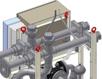
23 Additional piping between HX-unit and the main drives Secondary circuit inlet/outlet


24 ! NOTE


25 WARNING


26
27 WARNING


28


29 WARNING
30 WARNING
31
32
33 ! NOTE! NOTE
34 measurement range "ran high range low range "L0" "2" 2 switching point temperature "SPt" "on" actual switching point "12" "1" 2 1 "2" "off" (standard) normally closed "n.c." normally open / normally closed "0-C" normally open "n.o." (standard) small hysteresis "h05" hysteresis "HuS" standard hysteresis "h10" 1 "3" 3 switching output "S0" switching poin "SP" actual switching point "123" "1" "2" "3"
35


36 Maximum ambient temperature +35 C Maximum ambient relative humidity 60% VACON LIQUID COOLED NX DRIVE HXL040 Secondary circuit maximum +23 C (28 C-5 C) Primary circuit minimum +28 C (26 C+2 C)


37 Maximum ambient temperature +40 C Maximum ambient relative humidity 80% VACON LIQUID COOLED NX DRIVE HXL040 Secondary circuit maximum +33 C (38 C-5 C) Primary circuit minimum +38 C (36 C+2 C)


38 Maximum ambient temperature +40 C Maximum ambient relative humidity 50% VACON LIQUID COOLED NX DRIVE HXL040 Secondary circuit maximum +25 C (30 C-5 C) Primary circuit minimum +30 C (28 C+2 C)

 Dew-Point chart for")


39 Relative humidity, % Maximum ambient temperature +30 C Maximum ambient relative humidity 95% VACON LIQUID COOLED NX DRIVE HXL040 Secondary circuit maximum +40 C Primary circuit minimum +45 C (40 C+5 C) Dew-Point chart for ambient temperatures between 1013 mbar Primary circuit water temperature, C WARNING
40
41 WARNING
42 ! NOTE WARNING
43
44 Sensor reading [%] HXL-040, pure water, B=1 90,0 80,0 70,0 60,0 50,0 40,0 30,0 20,0 10,0 0, Flow [L/min}
45 Sensor reading [%] Sensor reading [%] HXL-040, 20% glycol, B=1,5 60,0 50,0 40,0 30,0 20,0 10,0 0, Flow [L/min} HXL-040, 40% glycol, B=2 45,0 40,0 35,0 30,0 25,0 20,0 15,0 10,0 5,0 0, Flow [L/min}
46 FACTOR B HXL-040 Glycol content factor B 2 1,9 1,8 1,7 1,6 1,5 1,4 1,3 1,2 1,1 1 0% 20% 40% GLYCOL CONTENT
47
48 Checking / adding the Air expansion vessel pre-pressure Nitrogen Changing the primary circuit liquid Monthly inspection Once a month Once a year Every 2 years Every 5 years x x x x
49 WARNING! NOTE WARNING HOT SURFACE


50 ! NOTE
51 WARNING


52


53
54
55 F1. 83 OverTempA A T1 T16
56 F1. 86 LowTemp A T1 T16
57 F1. 82 InletPressLow A T1 T16
58 F1. 51 External Fault F F1 F12
59 Height (Depth) Width Depth (Width)
60
61 100% FLOW = 120 l/min Plate heat exchanger route Flow Bypass route Flow Pressure drop plate heat exchanger Pressure drop 3-way valve Total pressure drop 100% 120 l/min 0% bar 1.3 bar 1.88 bar 75% 90 l/min 25% 30 l/min 0.3 bar 1.3 bar 1.6 bar 50% 60 l/min 50% 60 l/min 0.13 bar 1.3 bar 1.43 bar 25% 30 l/min 75% 90 l/min bar 1.3 bar 1.33 bar 0% 0 100% 120 l/min bar 1.3 bar => Pressure drop varies between 1.3 bar 1.88 bar 75% FLOW = 90 l/min Plate heat exchanger route Flow Bypass route Flow Pressure drop plate heat exchanger Pressure drop 3-way valve Total pressure drop 75% 90 l/min 0% bar 0.7 bar 1.0 bar 50% 60 l/min 25% 30 l/min 0.13 bar 0.7 bar 0.83 bar 25% 30 l/min 50% 60 l/min bar 0.7 bar 0.74 bar 0% 0 75% 90 l/min bar 0.7 bar => Pressure drop varies between 0.7 bar 1.0 bar 50% FLOW = 60 l/min Plate heat exchanger route Flow Bypass route Flow Pressure drop plate heat exchanger Pressure drop 3-way valve Total pressure drop 50% 60 l/min 0% bar 0.33 bar 0.46 bar 25% 30 l/min 25% 30 l/min bar 0.33 bar 0.37 bar 0% 0 50% 60 l/min bar 0.33 bar => Pressure drop varies between 0.33 bar 0.46 bar
62 Bolt tightening torque guidelines for metric flange connections with PP-V, PP-steel and PVC flanges Number of Nominal Pipe screws x thread Bolt tightening torque (Nm) diameter DN diameter d diameter Flat gasket up to max. pressure of 10 bar / 40 C Profile gasket up to max. pressure of 16 bar x M x M x M x M x M x M x M x M O-ring up to max. pressure of 16 bar
63 Bolt tightening torque for flange connections with Tesnit BA-S gasket s=2mm Max. temperature +50 C, flange DIN2642 PN10 Nominal diameter DN Number of screws x thread diameter Bolt tightening torque (Nm) 8.8 (bolt material) 10.9 (bolt material) Min torque Max torque Min torque Max torque 25 4 x M x M x M x M x M x M Bolt tightening torque for flange connections with Tesnit BA-S gasket s=2mm Max. temperature +50 C, flange DIN2633 PN16 Nominal diameter DN Number of screws x thread diameter Bolt tightening torque (Nm) 8.8 (bolt material) 10.9 (bolt material) Min torque Max torque Min torque Max torque 25 4 x M x M x M x M x M x M
64 Document ID: Vacon Ltd Member of the Danfoss Group Runsorintie Vaasa Finland DPD01505D Rev. D Sales code: DOC-INSNXHXL040+DLUK
vacon nx ac drives hxm120 cooling unit, ss-piping commissioning and maintenance manual
 vacon nx ac drives hxm120 cooling unit, ss-piping commissioning and maintenance manual WARNING HOT SURFACE! NOTE WARNING HOT SURFACE! NOTE 11571_uk WARNING ! NOTE! NOTE WARNING! NOTE Secondary
KTM 50 (DN ) Installation, maintenance and operating instructions
 Installation, maintenance and operating instructions") 52 762-306 09.2014 KTM 50 (DN 100-200) Installation, maintenance and operating instructions General High-performing and compact, these pressure-independent control valves for variable flow heating and
52 762-306 09.2014 KTM 50 (DN 100-200) Installation, maintenance and operating instructions General High-performing and compact, these pressure-independent control valves for variable flow heating and
Pressure relief valve
 Pressure relief valve Operating manual Series DHV 718 Version BA-2016.01.11 EN Print-No. 300 524 TR MA DE Rev001 ASV Stübbe GmbH & Co. KG Hollwieser Straße 5 32602 Vlotho Germany Phone: +49 (0) 5733-799-0
SonoMeter 30 Energy Meters
 Data Sheet SonoMeter 30 Energy Meters Description The Danfoss SonoMeter 30 is a range of ultrasonic, compact energy meters intended for measuring energy consumption in heating and cooling applications
Flowmeter. Original operating manual DFM
 Flowmeter Original operating manual Series DFM 165 350 Version BA-2016.08.09 EN Print-No. 300 458 TR MA DE Rev002 ASV Stübbe GmbH & Co. KG Hollwieser Straße 5 32602 Vlotho Germany Phone: +49 (0) 5733-799-0
Pressure relief valve
 Pressure relief valve Operating manual Series DHV 712 R Version BA-2016.01.19 EN Print-No. 300 472 TR MA DE Rev001 ASV Stübbe GmbH & Co. KG Hollwieser Straße 5 32602 Vlotho Germany Phone: +49 (0) 5733-799-0
Ball valve. Operating instructions for series. Version BA Print-No TR MA DE Rev001
 Ball valve Operating instructions for series Version BA-2016.02.05 Print-No. 300 587 TR MA DE Rev001 We reserve the right to make technical changes. Read carefully before use. Save for future use. ASV
Pressure relief valve DHV 712 DN 65-80: 0,5-10 bar, DN : 0,3-4 bar, DN 100: 0,5-6 bar
 Pressure relief valve DHV 7 DN 5-80: 0,5-0 bar, DN 5-00: 0, - bar, DN 00: 0,5 - bar Advantage for high pressure stability reliable reduction of pressure peaks and pulsations pressure setting possible at
Pressure Reducing Valve DMV 750 set range: bar
 Pressure Reducing Valve DMV 750 set range:.0-6.0 bar Advantage pressure setting possible at any time, also during operation hermetically sealed by valve diaphragm high level of operating safety and long
Pressure Relief Valve DHV 718
 Advantages frictionless components low maintenance low pressure increase up to fully opened valve constant low vibration controlling hermetically sealed by diaphragm for oscillating pumps for viscous media
Pneumatic proportional controller Types M Types FM Function tested for use of the float in Ex-zone 0
 Operating Manual LTIA5E Pneumatic proportional controller Types M Types FM Function tested for use of the float in Ex-zone 0 Contents 1. Safety Instructions 2. Conformity to standards 3. Technical data
Size : Ends : Min Temperature : Max Temperature : Materials : Cast iron body
 Size : Ends : Min Temperature : Max Temperature : DN 15 to DN 400 Flanges GN10/16-10 C + 120 C Max Pressure : 16 Bars up to DN 200 ( 10 bars over ) Specifications : Removable stainless steel filter Bolted
Differential Pressure Regulator Type Type 45-6 (0.1 to 1 bar, DN 15) Mounting and Operating Instructions EB 3226 EN
 Mounting and Operating Instructions EB 3226 EN") Differential Pressure Regulator Type 45-6 Type 45-6 (0.1 to 1 bar, DN 15) Mounting and Operating Instructions EB 3226 EN Edition March 2008 Contents Contents Page 1 Design and principle of operation...................
Differential Pressure Regulator Type 45-6 Type 45-6 (0.1 to 1 bar, DN 15) Mounting and Operating Instructions EB 3226 EN Edition March 2008 Contents Contents Page 1 Design and principle of operation...................
Connecting hoses. Type FS. Connecting hoses for the water-side connection of air- water systems and decentralised ventilation units PD FS 1
 X X testregistrierung Connecting hoses Type G½" external thread and flat seal G½" union nut and flat seal Connecting hoses for the water-side connection of air- water systems and decentralised ventilation
Engineering Data Sheet
 Page 1 of 6 CE MARKING AND THE PRESSURE EQUIPMENT DIRECTIVE 97/23/EC Valves must be installed into a well designed system and it is recommended that the system be inspected in accordance with the appropriate
Installation and Operating Instructions Bypass Flow Meter DST
 Installation and Operating Instructions Bypass Flow Meter DST DST_gb_A4_1.0.doc Version 1.0 1 von 10 Contents 1. Foreword... 3 2. Safety... 3 2.1. Symbol and meaning... 3 2.2. General safety directions
Pressure relief valve DHV 716 set range: 0,5-10,0 bar
 Pressure relief valve DHV 7 set range: 0,5-0,0 bar Advantage pressure setting possible at any time, also during operation optimum monitoring valves high reproducibility of the set pressure high level of
Size : Ends : Min Temperature : Max Temperature : Materials : Cast iron EN GJL 250 body. Reinforced lug for DN200 :
 Reinforced lug for DN200 : Size : Ends : Min Temperature : Max Temperature : DN 50 to 200 mm Between flanges ISO PN10/16 ( PN10 for DN200 ) - 10 C + 110 C Max Pressure : 10 Bars Specifications : Long neck
AVK SERIES 601, 602, 603 & 605 UNIVERSAL COUPLINGS, ADAPTORS & END CAPS INSTALLATION, OPERATION & MAINTENANCE MANUAL
 Instruction for use Thank you for selecting an AVK product. With correct use, the product is guaranteed to deliver a long and reliable service. This manual has been prepared to assist you with the installation,
Rotary valves HRB 3, HRB 4
 Data sheet Rotary valves HRB 3, HRB 4 Description HRB rotary valves can be used in combination with electric actuators AMB 162 and AMB 182. Features: Lowest leakage in class Unique position indicator (visible
Flow VA 520. incl. temperature measurement. Intelligent solutions for ac- for compressed air and gases R 1/4 (DN 8) DN 15 R 3/4 (DN 20) DN 25
 DN 15 R 3/4 (DN 20) DN 25") VA 520 incl. temperature R 1/4 (DN 8) DN 15 R 3/4 (DN 20) DN 25 R 1 1/4 (DN 32) DN 40 R 2 (DN 50) Intelligent solutions for ac- for compressed air and gases work according to the approved calorimetric
VA 520 incl. temperature R 1/4 (DN 8) DN 15 R 3/4 (DN 20) DN 25 R 1 1/4 (DN 32) DN 40 R 2 (DN 50) Intelligent solutions for ac- for compressed air and gases work according to the approved calorimetric
Pressure relief valve DHV 725 set range: 0,2-10,0 bar
 Pressure relief valve DHV 75 set range: 0, - 0,0 bar Advantage pressure setting possible at any time, also during operation optimum monitoring valves high reproducibility of the set pressure high level
Pressure Reducing Valve DMV 755
 Pressure Reducing Valve DMV 755 Nominal size DN 10 50 Nominal size 3/8 2 Nominal pressure PN 10 bar Features pressure setting range 1 to 9 bar control valve for reliable reduction of system pressures to
Pressure Reducing Valve DMV 750
 ASV Stübbe GmbH & Co. KG Hollwieser Straße 5 D-32602 Vlotho Fon +49 (0) 57 33-7 99-0 Fax +49 (0) 57 33-7 99-2 00 www.asv-stuebbe.de contact@asv-stuebbe.de Pressure Reducing Valve DMV 750 Advantages reduction
Pneumatic switch module 3/2-way valve (On/Off) Types P Types FP Function tested for use of the float in Ex-zone 0
 Types P Types FP Function tested for use of the float in Ex-zone 0") Operating Manual LTIA3E Pneumatic switch module 3/2-way valve (On/Off) Types P Types FP Function tested for use of the float in Ex-zone 0 Contents 1. Safety Instructions 2. Conformity to standards 3. Technical
Operating Manual LTIA3E Pneumatic switch module 3/2-way valve (On/Off) Types P Types FP Function tested for use of the float in Ex-zone 0 Contents 1. Safety Instructions 2. Conformity to standards 3. Technical
SLEEVED PLUG VALVES 2-WAY
 Specialty Valves 2-WAY ANSI/ASME CLASS 150 LBS Dimensions to ANSI B16.5 & B16.10 1 Six (6) top holes * 2 1/2 valves are made from 3 casting, but flanges are machined to 2 1/2 dimensions 1/2 4.25 108.00
SLEEVED PLUG VALVES 2-WAY
 Specialty Valves 2-WAY ANSI/ASME CLASS 150 LBS Dimensions to ANSI B16.5 & B16.10 1 Six (6) top holes * 2 1/2 valves are made from 3 casting, but flanges are machined to 2 1/2 dimensions 1/2 4.25 108.00
Instructions. Control Solution ICF 20-4, ICF 25-4, ICF ICF 40-4, ICF 20-6, ICF 25-6, ICF 32-6, ICF 40-6, Direction and Position.
 027R9789 Instructions Control Solution ICF 20-4, ICF 25-4, ICF 32-4. ICF 40-4, ICF 20-6, ICF 25-6, ICF 32-6, ICF 40-6, Direction and Position ICF xx-4 ICF xx-6 ICF xx-4 / ICF xx-6 with ICM 027R9789 Fig.
Installation, Operation and Maintenance Manual for Back Pressure Regulator
 Installation, Operation and Maintenance Manual for Back Pressure Regulator Model 8860 2009 Groth Corporation IOM-8860 Rev. B 12541 Ref. ID: 95565 Page 2 of 13 Table of Contents I. INTRODUCTION 3 II. DESIGN
Installation and commissioning instructions 255 series and 256 series
 Installation and commissioning instructions 255 series and 256 series Table of contents 1 General information... 3 1.1 About these instructions... 3 1.2 About this product... 3 1.3 Appropriate usage...
OPERATING MANUAL. Contents. Bottom outlet ball valve Type ecoline
 OPERATING MANUAL Bottom outlet ball valve Type ecoline Contents 1 General Information 2 Safety 3 Packing, Handling, Storing 4 Product description 5 Preparation, Assembly 6 Commissioning 7 Handling 8 Attendance
Ref GAS WAFER BUTTERFLY VALVE. Model/Ref:
 Model/Ref: 1141 www.lauridsenindustri.com Size : Ends : Min Temperature : Max Temperature : DN 32/40 to 200 mm Between ISO PN10/16 and ANSI150 flanges - 20 C + 60 C Max Pressure : 5 Bars Specifications
Centrifugal Gas Separator ZGA. Operating Manual. Dimensions, weights and other technical data are subject to changes.
 Centrifugal Gas Separator ZGA Operating Manual Am Neuen Rheinhafen 4 - D-67346 Speyer Postfach 1709 - D-67327 Speyer Phone: +49 (6232) 657-0 Fax: +49 (6232) 657-505 Internet: http://www.burmt.de Email:
Instructions. Control Solution ICF 20-4, ICF 25-4, ICF ICF 40-4, ICF 20-6, ICF 25-6, ICF 32-6, ICF 40-6, Direction and position.
 027R9782 Instructions Control Solution ICF 20-4, ICF 25-4, ICF 32-4. ICF 40-4, ICF 20-6, ICF 25-6, ICF 32-6, ICF 40-6, Direction and position ICF xx-4 ICF xx-6 ICF xx-4 / ICF xx-6 with ICM ICM 027R9782
SITRANS F I Gardex. Flowmeter. SITRANS F I Intra/Prima. Flap Flowmeter. Contents. English. General 1. SITRANS F I Gardex 2. SITRANS F I Intra/Prima 3
 Contents SITRANS F I Gardex Flowmeter English General 1 SITRANS F I Gardex 2 SITRANS F I Intra/Prima 3 SITRANS F I Intra/Prima Flap Flowmeter Instructions A5E00129182 Version 02 09/2003 SITRANS F ED Automatic
Installation, Operation and Maintenance Instructions for Direct Hot Water Storage Vessels
 OM003 Installation, Operation and Maintenance Instructions for Direct Hot Water Storage Vessels The operating and maintenance instructions contained within this package are for standard storage vessels
Modular valve block. Operating manual Series MVB 100/200. Version BA EN Print-No TR MA DE Rev001
 Modular valve block Operating manual Series MVB 100/200 Version BA-2016.04.20 EN Print-No. 300 627 TR MA DE Rev001 ASV Stübbe GmbH & Co. KG Hollwieser Straße 5 32602 Vlotho Germany Phone: +49 (0) 5733-799-0
Pressure Reducing Valve DMV 755 set range: 1,0-9,0 bar
 Pressure Reducing Valve DMV 755 set range:,0-9,0 bar Advantage pressure setting possible at any time, also during operation high reproducibility of the set pressure high level of operating safety and long
Model MTB-ASME Vertical Bladder Tanks
 DATA SHEET Model MTB-ASME Vertical Bladder Tanks Features n UL Listed for use with various proportioners and foam concentrates n 175 psi (12.1 bar) maximum allowable working pressure (design pressure)
L21S/SR/ST Glass Level Gauges
 L21S/SR/ST Glass Level Gauges Doc. no.: 150, en_cat_l21s/sr/st, 12/2014 Type of code Example: L21ST/1450/AANSI 3/4 150Lb RF/Large chamber Code 1 Basic type L21 2 Type of gauge S Tubular level gauge SR
VGG... VGF... VGH... Gas Valves. Building Technologies HVAC Products VGG... VGF... VGH...
 7 66 VGG... VGF... VGH... Gas Valves VGG... VGF... VGH... Single valves of class A for installation in gas trains Safety shutoff valves conforming to EN 161 in connection with SKP... actuators Suitable
Remeha Quinta Cascade guide
 Technical information Remeha Quinta Cascade guide Cascade guide Cascade systems 2 Remeha Quinta Cascade guide TABLE OF CONTENTS FOREWORD 4 1 GENERAL DESCRIPTION OF CASCADE SYSTEMS 4 1.1 Optimum number
3-Way Pressure-Reducing Cartridge, Size 2 4
 -Way Pressure-Reducing Cartridge, Size 2 Q max = 2 l/min, p max = 25 bar Spool-type design, direct acting, with manual adjustment 1 Description Compact construction for cavity type AM /- UNF to Bucher
Flamco Flamco-Fill STA Flamco-Fill STM
 STA STM Typ STA 5936 Typ STM 5937 GB Installation and operating instructions 1999, 2 Contents GB UK Limited P.O. Box 9, Washway Lane, St. Helens, Merseyside WA10 6FE United Kingdom Telephone: 01744 744744
Model MTB-ASME Vertical Bladder Tanks
 DATA SHEET Model MTB-ASME Vertical Bladder Tanks Features n UL Listed for use with various proportioners and foam concentrates n 175 psi (12.1 bar) maximum allowable working pressure (design pressure)
Installation, Operation and Maintenance Instructions for Mild Steel Buffer Vessel
 OM006 Installation, Operation and Maintenance Instructions for Mild Steel Buffer Vessel The operating and maintenance instructions contained within this package are for standard mild steel buffer vessels
The valves are used in combination with AMV(E) 130/140, AMV(E) 130H/140H and AMV(E) 13 SU actuators. DN k VS
 130/140, AMV(E) 130H/140H and AMV(E) 13 SU actuators. DN k VS") Description VZ 2 VZ 3 VZ 4 VZ valves provie a high quality, cost effective solution for the control of hot an/or chille water for fan coil units, small reheaters, an recoolers in temperature control systems.
Description VZ 2 VZ 3 VZ 4 VZ valves provie a high quality, cost effective solution for the control of hot an/or chille water for fan coil units, small reheaters, an recoolers in temperature control systems.
Horizontal Bladder Tanks
 DATA SHEET Horizontal Bladder Tanks Features UL Listed and FM Approved for use with various ANSUL proportioners and foam concentrates 175 psi (12.1 bar) maximum allowable working pressure (design pressure)
Armatures for analytical probes
 Armatures for analytical probes For many different types of installations and applications Large range of probe holders General purpose, water treatment, food & beverage, pharmaceutical applications Type
Two-port valves, male threaded, PN25
 4 379 Two-port valves, male threaded, PN25 VVG55... Two-port valves, externally threaded, PN25 Bronze Rg5 DN15... 25 mm (½"... 1") k vs 0.25... 6.3 m 3 /h Stroke 5.5 mm Suitable for type SQS35... or SQS65...
Electro-Pneumatic Converter YT-940 SERIES
 Electro-Pneumatic Converter YT-940 SERIES PRODUCT MANUAL VERSION 1.00 Contents 1. Introduction 3 1.1 General information for the users. 3 1.2 Manufacturer Warranty 3 1.3 Explosion Proof Warning. 4 2. Product
Differential pressure and flow controller (PN 16) AVPQ - return mounting, adjustable setting
 AVPQ - return mounting, adjustable setting") Data sheet Differential pressure and flow controller (PN 16) AVPQ - return mounting, adjustable setting Description AVPQ is a self-acting differential pressure and flow controller primarily for use in
Data sheet Differential pressure and flow controller (PN 16) AVPQ - return mounting, adjustable setting Description AVPQ is a self-acting differential pressure and flow controller primarily for use in
VGG... VGF... VGH... Gas Valves. Siemens Building Technologies HVAC Products VGG... VGF... VGH...
 7 636 VGG... VGF... VGH... Gas Valves VGG... VGF... VGH... Single valves of class A for installation in gas trains Safety shutoff valves conforming to EN 161 in connection with SKP... actuators Suitable
Liquid level glasses, type LLG REFRIGERATION AND AIR CONDITIONING. Technical leaflet
 Liquid level glasses, type LLG 185-1550 REFRIGERATION AND AIR CONDITIONING Technical leaflet Introduction LLG are liquid level glasses in ductile steel which meets the strictest requirements on industrial
Differential pressure controller (PN 16) AHP - return mounting, adjustable setting
 AHP - return mounting, adjustable setting") Data sheet Differential pressure controller (PN 16) AHP - return mounting, adjustable setting Description DN 15-40 DN 50 DN 65-100 AHP is a self-acting differential pressure controller primarily for use
Data sheet Differential pressure controller (PN 16) AHP - return mounting, adjustable setting Description DN 15-40 DN 50 DN 65-100 AHP is a self-acting differential pressure controller primarily for use
Steam Trap BK BK 212-ASME. Original Installation Instructions English
 Steam Trap BK 212.. BK 212-ASME EN English Original Installation Instructions 810609-02 1 Contents Page Important Notes Usage for the intended purpose... 3 Safety note... 3 Danger... 3 Attention... 3 Application
SV5 Safety Valve Installation and Maintenance Instructions
 3120036/3 IM-S13-12 CH Issue 3 SV5 Safety Valve Installation and Maintenance Instructions 1. General specification 2. Supply 3. Before fitting the valve 4. Installation 5. Damage prevention 6. Commissioning
Mounting and Operating Instructions EB 3007 EN. Self-operated Pressure Regulators. Differential Pressure Regulators (opening) Type Type 42-25
 Type Type 42-25") Self-operated Pressure Regulators Differential Pressure Regulators (opening) Type 42-20 Type 42-25 Type 42-20 Differential Pressure Regulator Type 42-25 Differential Pressure Regulator Mounting and Operating
Self-operated Pressure Regulators Differential Pressure Regulators (opening) Type 42-20 Type 42-25 Type 42-20 Differential Pressure Regulator Type 42-25 Differential Pressure Regulator Mounting and Operating
Size : Ends : Min Temperature : Max Temperature : Materials : Cast iron body
 Size : Ends : Min Temperature : Max Temperature : DN 40 to DN 300 Flanges R.F. PN10/16-10 C + 80 C Max Pressure : 16 Bars up to DN200 Specifications : Removable stainless steel filter Bolted bonnet with
B2KL: 6-way ball valve with male thread, PN 16
 Product data sheet 3.1 58.001 K: 6-way ball valve with male thread, PN 16 How energy efficiency is improved fficiency means precise control and low actuating forces eatures 6-way ball valve for changeover
Seated valves VRB 3, VRG 3
 Data sheet Seated valves VRB 3, VRG 3 Description VRB, VRG valves provide a quality, cost effective solution for most water and chilled applications. These valves may be used with glycol concentrations
Gas Appliance Pressure Regulators with integrated gas filter. FRI/6 Series
 Gas Appliance Pressure Regulators with integrated gas filter FRI/6 Series CSA Certified ANSI Z21.18 / CSA 6.3 Gas Appliance Pressure Regulator File # 1135455 EU Gas Appliance Directive EN 88 CE-0087 AU
Vortex Flow Meter Wafer or Flange Connection. - Steam - Liquid - Gas
 Vortex Flow Meter Wafer or Flange Connection - Steam - Liquid - Gas Working Principle & Circuit Diagram Working Principle When a column body placed in flowing fluids in pipe, a series of vortices will
Brazed Heat Exchangers
 Brazed Heat Exchangers The Brazed Heat Exchanger less is more The brazed plate heat exchanger is the most compact heat exchanger on the market today. Its high heat transfer efficiency in combination with
AVP-F. p setting range (bar) Code No. 003H6200
 Code No. 003H6200") Data sheet Differential pressure controller (PN 16) AVP - return and flow mounting, adjustable setting AVP-F - return mounting, fixed setting Description The controller has a control valve, an actuator
Data sheet Differential pressure controller (PN 16) AVP - return and flow mounting, adjustable setting AVP-F - return mounting, fixed setting Description The controller has a control valve, an actuator
Gas powered stop valves, type GPLX REFRIGERATION AND AIR CONDITIONING. Technical leaflet
 Gas powered stop valves, type GPLX 80-150 REFRIGERATION AND AIR CONDITIONING Technical leaflet Technical leaflet Gas powered stop valves, type GPLX 80-150 Contents Page Introduction........................................................................................3
Technical Manual. Liquid Level Transmitter CT801-LB/S
 CT801-LB/S Technical Manual SAS au Capital de 2 158 244-444 871 933 R.C.S. Bourges - APE : 2651B Headquarter : 9, rue Isaac Newton - 18000 Bourges - France Technical Manual CT801-LB/S 1 st Edition Released
INDUSTRIAS IBAIONDO, HYDROPNEUMATIC TANKS
 IBAIONDO, HYDROPNEUMATIC TANKS IBAIONDO, INTRODUCTION Hydropneumatic tanks are designed to be used in potable water supply installations as a part of the pressure booster set in order to ensure the adequate
INSTRUCTION MANUAL Pressure Relief Device LPT
 INSTRUCTION MANUAL Pressure Relief Device LPT 5COV475800 LPT REV00 CONTENT: 1 SAFETY 1.1 Safety instructions 2 1.2 Specified applications 2 1.3 Safety notes on the equipment operation 2 2 PRESSURE RELIEF
Vacuum Saving Valve Series ZP2V How to Order ZP2V A5 03 Connection thread symbol for the pad Male thread connection Symbol Thread Applicable fixed ori
 Vacuum Saving Valve Series ZP2V Model Selection Select the quantity of vacuum saving valves that can be used with one vacuum generator. Selection Conditions Work piece: No leakage and several sizes Required
AVS32 Stainless Steel Air Vent for Steam Systems Installation and Maintenance Instructions
 1234150/3 IM-P123-17 ST Issue 3 AVS32 Stainless Steel Air Vent for Steam Systems Installation and Maintenance Instructions 1. General safety information 2. General product information 3. Installation 4.
Model MTB-ASME Horizontal Bladder Tanks
 DATA SHEET Model MTB-ASME Horizontal Bladder Tanks Features n UL Listed and FM Approved for use with various proportioners and foam concentrates n 175 psi (12.1 bar) maximum allowable working pressure
GAS PRESSURE CONTROL UNIT TYPE 132
 GAS PRESSURE CONTROL UNIT TYPE 132 OUR DIVERSITY IS YOUR PROFIT. Gas Pressure Regulator Type 132 Scope of Application Scope of type 132 gas pressure regulator is to maintain the output pressure at a constant
The affordable consumption counter for compressed air and gases R 3 /4 (DN 20)
") VA 420 new The affordable consumption counter for compressed air and gases R 1 /4 (DN 8) DN 15 R 3 /4 (DN 20) DN 25 R 1 1 /4 (DN 32) DN 40 R 2 (DN 50) With mit und and ohne without Flansch flange Intelligent
VA 420 new The affordable consumption counter for compressed air and gases R 1 /4 (DN 8) DN 15 R 3 /4 (DN 20) DN 25 R 1 1 /4 (DN 32) DN 40 R 2 (DN 50) With mit und and ohne without Flansch flange Intelligent
The valves are used in combination with AMV(E) 130/140, AMV(E) 130H/140H and AMV(E) 13 SU actuators. DN k VS
 130/140, AMV(E) 130H/140H and AMV(E) 13 SU actuators. DN k VS") Description VZ 2 VZ 3 VZ 4 VZ valves provie a high quality, cost effective solution for the control of hot an/or chille water for fan coil units, small reheaters, an recoolers in temperature control systems.
Description VZ 2 VZ 3 VZ 4 VZ valves provie a high quality, cost effective solution for the control of hot an/or chille water for fan coil units, small reheaters, an recoolers in temperature control systems.
Spiratec ST14, ST16 and ST17 Sensor Chambers and sensors
 0862050/1 IM-P086-18 MI Issue 1 Spiratec ST14, ST16 and ST17 Sensor Chambers and sensors Installation and Maintenance Instructions 1. Safety Information 2. General product information 3. Installation 4.
Supratec. von-drais-straße 7 D Simmern/Hunsrück Fon: +49 ( 67 61) Fax: +49 ( 67 61)
 Fax: +49 ( 67 61)") O X Y FLEX - OM O VA L-MEMBRANE-TUBE-DIFFUSER for fine bubble aeration of liquids UND GESELLSCHAFT FÜR UMWELT- VERFAHRENSTECHNIK mbh von-drais-straße 7 D-55469 Simmern/Hunsrück Fon: +49 ( 67 61) 9 65 09-00
O X Y FLEX - OM O VA L-MEMBRANE-TUBE-DIFFUSER for fine bubble aeration of liquids UND GESELLSCHAFT FÜR UMWELT- VERFAHRENSTECHNIK mbh von-drais-straße 7 D-55469 Simmern/Hunsrück Fon: +49 ( 67 61) 9 65 09-00
Installation, Operation and Maintenance Instructions Buffer Vessel OM006
 Installation, Operation and Maintenance Instructions Buffer Vessel OM006 Calorifiers Heat Exchangers Pressurisation Units Sales Tel: 01457 835700 Sales Fax: 01457 832700 E-mail: sales@gmsthermal.co.uk
Gas Pressure Switch for DMV safety shutoff valves
 Gas Switch for DMV safety shutoff valves GAO-A GMH-A GML-A UL Listed UL 353 File # MH 1668 CSA Certified CSA C. No. LR 53 File # 0157 FM Approved Class 3510, 3530 File # J.I. 1Y9A9.AF Commonwealth of Massachusetts
Vertical Bladder Tanks
 DATA SHEET Vertical Bladder Tanks Features UL Listed and FM Approved for use with various ANSUL proportioners and foam concentrates 175 psi (12.1 bar) maximum allowable working pressure (design pressure)
Water Safety Shut-off Valve HON 790
 Water Safety Shut-off Valve HON 790 790.20 OPERATING AND MAINTENANCE INSTRUCTIONS/ SPARE PARTS EDITION 01/2017 Serving the Gas Industry Worldwide Contents Page 1. General information 3 1.1 Safety information
Materials : Stainless steel ASTM A351 CF8M
 Certificat 3.1 Size: Ends : Min Temperature : Max Temperature : DN 15 to DN 200 PN16 Flanges R.F. - 20 C + 200 C Max Pressure : 16 Bars Specifiations : Removable stainless steel filter Bolted bonnet with
Combined Pressure / Vacuum Relief Valve KITO VD/o
 KITO VD/o DN D H kg* vacuum setting (mbar) pressure DIN ANSI DIN ANSI min max min max** 50 PN 16 2 220 332 351 11 3 50 10 75 80 PN 16 3 260 367 387 145 3 50 10 70 100 PN 16 4 260 368 393 178 3 50 10 80
Mounting and Operating Instructions EB 3007 EN. Self-operated Pressure Regulators. Type Type Differential Pressure Regulators (opening)
") Self-operated Pressure Regulators Type 42-20 Type 42-25 Differential Pressure Regulators (opening) Translation of original instructions Type 42-20 Differential Pressure Regulator Type 42-25 Differential
Self-operated Pressure Regulators Type 42-20 Type 42-25 Differential Pressure Regulators (opening) Translation of original instructions Type 42-20 Differential Pressure Regulator Type 42-25 Differential
OFFICINE OROBICHE S.p.A. 1/9
 OFFICINE OROBICHE S.p.A. 1/9 INSTRUCTIONS MANUAL FOR LEVEL SWITCHES SERIES 7000 mod. 7250 AND 7400 Electric 1. INSTRUMENT DESCRIPTION Series 7000 level switches have been designed for external lateral
TANDEM MODULATOR FOR OUTLET GAS FLOW: STEPPED (836 TANDEM) - CONTINUOUS (837 TANDEM) SERVO-CONTROLLED PRESSURE REGULATOR
 - CONTINUOUS (837 TANDEM) SERVO-CONTROLLED PRESSURE REGULATOR") SIT Group 836-837 TANDEM MULTIFUNCTIONAL GAS CONTROL MODULATOR FOR OUTLET GAS FLOW: STEPPED (836 TANDEM) - CONTINUOUS (837 TANDEM) SERVO-CONTROLLED PRESSURE REGULATOR ALL ADJUSTMENTS ACCESSIBLE FROM ABOVE
SIT Group 836-837 TANDEM MULTIFUNCTIONAL GAS CONTROL MODULATOR FOR OUTLET GAS FLOW: STEPPED (836 TANDEM) - CONTINUOUS (837 TANDEM) SERVO-CONTROLLED PRESSURE REGULATOR ALL ADJUSTMENTS ACCESSIBLE FROM ABOVE
Seated valves (PN 16) VF 2 2-way valve, flange VF 3 3-way valve, flange
 VF 2 2-way valve, flange VF 3 3-way valve, flange") Data sheet Seated valves (PN 16) VF 2 2-way valve, flange VF 3 3-way valve, flange Description VF 2 VF 3 VF 2 and VF 3 valves provide a quality, cost effective solution for most water and chilled applications.
Data sheet Seated valves (PN 16) VF 2 2-way valve, flange VF 3 3-way valve, flange Description VF 2 VF 3 VF 2 and VF 3 valves provide a quality, cost effective solution for most water and chilled applications.
MUELLER. A A Adjustable. Vertical Indicator Posts. Reliable Connections. General Information 2. Technical Data 3.
 Installation Instructions manual MUELLER table of contents PAGE A-20806 A-20807 Adjustable General Information 2 Technical Data 3 Dimensions 4 Installation 5-6 Parts 7 Maintenance 8 Vertical Indicator
SCA Series Inverted Bucket Steam Traps
 0770050/5 IM-P077-06 ST Issue 5 SCA Series Inverted Bucket Steam Traps Installation and Maintenance Instructions 1. General safety information 2. General product information 3. Installation 4. Commissioning
Gas Pressure Switch for DMV safety shutoff valves
 Gas Switch for DMV safety shutoff valves GAO-A GMH-A GML-A UL Listed UL 353 File # MH 1668 CSA Certified CSA C. No. LR 53 File # 0157 FM Approved Class 3510, 3530 File # J.I. 1Y9A9.AF Commonwealth of Massachusetts
Flamco Airfix D-E. Installation and operating instructions. 1999, Flamco eps
 Airfix D-E 6442.eps GB Installation and operating instructions 1999, Exclusion of liability All operation and maintenance related technical information, data and instructions contained in these installation
Variable Area Flow Meters. VS Series
 Variable Area Flow Meters VS Series Precise measuring in water flow Design and function VS series fl ow meters operate with the fl oat principle. A fl oat is located in a conical plastic tube. The fl oat
Operating instructions Safety Rope Emergency Stop Switches ZB0052 / ZB0053 ZB0072 / ZB0073
 Operating instructions Safety Rope Emergency Stop Switches UK ZB0052 / ZB0053 ZB0072 / ZB0073 7390878 / 02 03 / 2011 Contents 1 Safety instructions...3 2 Installation / set-up...4 2.1 Applications...4
Monitoring device NTS 30
 P R O D U C T I N F O R M A T I O N Electronic level- and temperature monitoring device Monitoring device NTS 30 Contents Description Description... 2 Operating... 3 Design and electrical data... 4 Circuit
Instruction Manual SB02, SB03, SB04 All metal flow limiter
 Instruction Manual SB02, SB03, SB04 All metal flow limiter PKP Prozessmesstechnik GmbH Borsigstraße 24 D-65205 Wiesbaden-Nordenstadt Tel.: ++49-(0)6122-7055-0 Fax: ++49-(0)6122-7055-50 Email: info@pkp.de
TECHNICAL DATA. Q = C v P S
 January 6, 2012 Preaction 333a 1. Description Viking supervised Surefire Preaction Systems Utilize the Viking G-3000P Valve. The small profile, lightweight, pilot-operated Viking G-3000P Valve comes complete
Operating instructions - Translation of the original -
 Operating instructions - Translation of the original - 5093 xxx 000-xxx Check valve DN25 - DN100 EPDM O-Ring-design Intermediate flanged with welding ends 27.1.12 KIESELMANN GmbH Paul-Kieselmann-Str.4-10
Electrically Operated Pressure-Relief Cartridge, Size 10
 Electrically Operated Pressure-Relief Cartridge, Size 1 Q max = 14 l/min (37 gpm), p max = bar (5 psi) seated pilot stage, spool-type design, with remote contral port Z Series WUVPOC-2, WUVPLC-2 1 Description
TECHNICAL DATA. Q = C v P S
 January 6, 2012 Preaction 348a 1. Description Viking supervised Surefire Preaction Systems utilize the Viking G-6000P Valve. The small profile, lightweight, pilot operated Viking G-6000P Valve comes complete