HOMOLOGATION OF KART ENGINE
|
|
|
- Tamsin Matthews
- 6 years ago
- Views:
Transcription


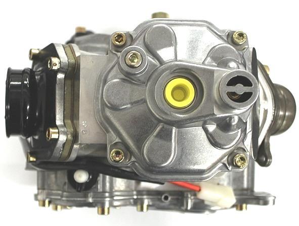
1 HOMOLOGATION OF KART ENGINE ROTAX SENIOR MAX Valid From 1 st June 2011 Number of pages 21 This Homologation Form reproduces descriptions, illustrations and dimensions of the engine at the moment of the MSA Homologation. This document may be supplemented by official amendment. This document must be read in conjunction with the appropriate Class Regulations. Photo of drive side of engine Photo of opposite side of engine 0BSIGNATURE AND STAMP OF THE MSA Date: 1 st June 2011 Signed by: John Ryan Position: MSA Technical Executive Any reproduction must be authorised by the MSA MSA


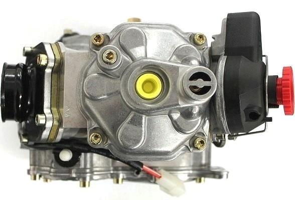
2 Photo of rear of engine Photo of front of engine Photo of top of engine MSA
3 LIST OF APPICES No. Type Description Pg No. Date 1 Supplement Rotax Junior Max & Minimax 22 1 st June Additional Info Clutch measurement guidelines 26 1 st June Additional Info Senior Max ID cards and seals 28 1 st June Additional Info Junior Max & Minimax ID cards and seals 30 1 st June Variant Alternative radiator 32 1 st June Variant Alternative radiator 34 1 st June Variant Alternative reed valve assembly 36 1 st June Variant Alternative exhaust power valve assembly 37 1 st June Variant Alternative pistons 39 1 st June Variant Alternative cylinder (Senior) 40 1 st June Variant Alternative cylinder (Senior) 41 1 st June Variant Alternative cylinder (Junior) 43 1 st June Variant Alternative cylinder (Junior) 45 1 st June Variant Alternative crankshaft components 47 1 st June Variant Alternative balance shaft 49 1 st June Variant Alternative crankcase 50 1 st June Variant Alternative balance gears (steel) 51 1 st June Variant Alternative balance gears (plastic) 52 1 st June Variant Alternative clutch 53 1 st June Variant Alternative clutch 55 1 st June Variant Alternative intake silencer support bracket 56 1 st June Variant Alternative piston ring 57 1 st August Additional Info Float bowl plug screw clarification th December Additional Info Minimax inlet throttle restrictor (cancelled see App. 54) 60 1 st January Variant Alternative fuel filter 62 1 st February Amendment Float needle valve 63 1 st July Variant Additional exhaust steel isolating mat (cancelled see App. 28) 65 1 st January Erratum Additional exhaust steel isolating mat 66 1 st January Amendment Intake silencer tube and carburettor socket 68 1 st January Variant New production crankcase 69 1 st January Variant Clutch/reduction gear cover th January Amendment Exhaust valve gasket 72 1 st May Additional Info Dell orto carburettor measurements th February Erratum Clutch dimensions 77 6 th February Variant Alternative machining finish on exhaust socket st January Variant Alternative crankcase colour November Variant Alternative gear cover & head colours November Variant Alternative con rod November Variant Alternative air filter element (cancelled see App. 55) November Amendment Ignition pick-up gasket November Variant Alternative clutch drum November 2015 MSA a
4 42 Amendment Deletion of piston ring markings November Variant Alternative inlet manifold December Variant Alternative ignition system January Variant Alternative exhaust valve January Variant Alternative carburettor January Amendment Carburettor float arm height January Variant Alternative exhaust January Variant Alternative cylinder with CNC machining (Junior) January Variant Alternative inlet manifold January Amendment Combustion chamber inserts January Amendment Gudgeon pin minimum weight January Amendment Atomiser measurements January Amendment Mini Max inlet throttle restrictor spacer January Amendment Alternative air filter element January Amendment Exhaust port timing January Variant Alternative crankcase colour January Additional Info Needle Jet Atomiser finish March Erratum Alternative ignition system August 2017 Last updated 09 August 2017 MSA b


5 TECHNICAL INFORMATION 1. Squish Gap 1.1 Minimum: 0.95mm Average of two measurements. To be measured on both sides across the piston pin axis using 2.0mm solder. (Squish can be adjusted by using original Rotax cylinder base gaskets). 2. Combustion Chamber Insert 2.1 Only inserts with the following ID codes will be permitted: Casted wording Rotax and/or MADE IN AUSTRIA must be present. 2.3 Heights of combustion chamber insert: A: 27.55mm + 0.0mm, - 0.1mm B: 28.80mm ± 0.2mm MSA

6 2.4 Combustion chamber insert profile must be checked with the Rotax profile gauge (part no ). The profile of the combustion chamber insert should approximately follow the profile of the gauge. NB: This check is just for reference, in case of doubt detailed measurements in accordance with the diagram should be taken. 2.5 Volume of combustion chamber mounted on engine, with piston at TDC: 10.7cc (to the top of the spark plug thread) minimum using a Class A or digital burette. 3. Piston & Rings 3.1 Coated cast aluminium piston, with one piston ring. Inside of piston to be marked ELKO (1) and MADE IN AUSTRIA (2). MSA


7 3.2 Machined areas are: Crown of piston, outside diameter, groove for piston ring, bore for piston pin, inside diameter at bottom of piston skirt and some pre-existing factory removal of flashing at the cut out of the piston skirt (A). All other surfaces are not machined and have cast finish. 3.3 One 1mm rectangular piston ring marked with one of: E CRY K ROTAX ELKO CRY 4. Gudgeon Pin 4.1 Material: Magnetic Steel 4.2 Dimensions: 4.3 Minimum weight: 32.10g MSA


8 5. Cylinder 5.1 Material: Light alloy with GILNISIL plating. Any re-plating is not permitted. Any additional fettling or machining is not permitted. 5.2 Cylinder with one main exhaust port. 5.3 Bore: mm (max.). Measured 10mm above the exhaust port. 5.4 Cylinder with exhaust power valve. Cylinder must be marked with ROTAX and part number Height of Cylinder: 87.00mm +0.10mm, -0.05mm 5.6 All transfer ports and passages have cast finish surfaces except for some removal (by the manufacturer) of cast burr at the inlet passage and exhaust port and passages. MSA


9 5.7 All ports may have chamfered edges to prevent ring snagging. Any additional fettling or machining is not permitted. The upper edge of the central boost port may show signs of factory machining. 5.8 The sealing flange for the exhaust socket may show either cast finish surface or signs of machining from the manufacturer. Cast finish: Machined finish: 5.9 The exhaust port may show signs of factory CNC machining all round. It may also show signs of partial factory manual grinding to eliminate minor casting defects and NIKASIL burr at the end of the NIKASIL plating. Any additional fettling or machining is not permitted. 6. Exhaust Port Timing 6.1 The exhaust port timing must be checked using the Rotax template (part no ). Insert the template into the cylinder, so that it is touching the cylinder wall and so that the finger of the template is located in the middle of the exhaust port (highest point). Move the template upwards, until the finger is touching the top edge of the exhaust port. Insert a feeler gauge between the top of the cylinder and the template. It must not be possible to fit a feeler gauge of 0.75mm between the top of the cylinder and the template. MSA


10 15.5mm Homologation N 7. Exhaust Valve 7.1 Exhaust valve as supplied by the manufacturer with no modification permitted. Compression spring must be fitted. 7.2 Length: 36.5mm +0.2mm, -0.3mm Width of collar: 4.8mm ±0.3mm 7.3 With the piston moved in the direction of the top of the cylinder and just covering the exhaust port, it must be possible to insert the Rotax exhaust gauge (part no ) until it stops at the surface of the cylinder. It must not be possible to insert a 0.05mm feeler gauge beneath the exhaust gauge. 7.4 Exhaust power valve stud Exhaust power valve piston (part no ) (part no ) Exhaust power valve bellow Exhaust power valve bellow spring (part no ) (part no ) Exhaust power valve adjustment screw (part no ) MSA


11 7.5 An additional exhaust valve bellow spring (part no ) may be used on all exhaust valves. 7.6 One original exhaust valve gasket may be fitted between the exhaust valve housing and cylinder. The fitting of more than one exhaust valve gasket is not permitted. 8. Inlet System 8.1 Inlet manifold must be marked with ROTAX (1) and the ID code (2) 2 1 Some factory flash removal may be present in the area of the inside contour and the carburettor stop mounting face. This is a manual trimming operation consisting of a small corner break of less than 3mm in width. No additional grinding or machining is permitted. 8.2 The reed valve assembly (part no ) consists of two petal stops and two reeds consisting of three petals each. The thickness of the reeds is 0.60mm ± 0.08mm. The reed stops must form an arc, no other shaping is permitted. One original Rotax reed block gasket must be used between the reed block and cylinder. MSA

. 9.3 Silver plated Big End Thrust Washer. 9.4 Big End Bearing with 16 loose needle rollers.")
12 8.3 One original Rotax reed block gasket must be used between the reed block and cylinder. The fitting of more than one reed block gasket is not permitted. 9. Crankshaft 9.1 Stroke: 54.5mm ±0.1mm 9.2 Con rod with part number 367 marked on shaft: No modification is allowed. Shaft of con rod is not machined (copper plated). 9.3 Silver plated Big End Thrust Washer. 9.4 Big End Bearing with 16 loose needle rollers. 9.5 Plastic Water Pump Driver Gear (part no ). MSA

. 10.")

13 9.6 Crankshaft: 9.7 Main Bearing (part no ) FAG plastic cage. 10. Balance Shaft 10.1 Balance shaft (part no or ) must be installed and operational No modifications allowed (see drawings) Surface (1) is not machined and must be cast surface Measurement from centre of balance shaft to outer diameter of flyweight of balance shaft must not be lower than 21.5mm 10.5 Minimum weight of dry balance shaft: 255g MSA
. Minimal fettling is permitted to repair damaged surfaces due to mechanical failure. 11.2 Crankcase centre to cylinder support face: 69.30mm ± 0.")
14 11. Crankcase 11.1 Rotax part no , as supplied by manufacturer without any additional grinding, polishing or machining other than specified below. No modifications are allowed (see drawing below). Minimal fettling is permitted to repair damaged surfaces due to mechanical failure Crankcase centre to cylinder support face: 69.30mm ± 0.1mm 11.3 Crankcase may have additional machining on the balance gear and drive side. Example of machining shown below. Dimensions for additional machining: Maximum diameter of the clearance bore: 92.50mm Maximum depth of the clearance bore on the balance gear side: 10.80mm Maximum depth of the clearance bore on the clutch side: 8.80mm 11.4 One original crankcase and gear cover gasket must be fitted. The fitting of more than one crankcase gasket or gear cover is not permitted. No remachining is allowed. MSA

: 210mm Measured from outlet of cable at ignition coil to outlet of cable at spark plug connector (= visible length of the wire) 13.")

15 12. Balance Drive mm thick steel balance gears (Rotax part no ) must be installed and must be aligned as shown below. 13. Ignition Unit 13.1 DENSO digital battery unit, variable ignition timing with no adjustment. Triggering slot in crankshaft flywheel The ignition coil must have the following markings moulded in the casing: and DENSO The ignition coil must show three pins at the terminal Connector housing of ignition coil must be either green or black colour Minimum length of ignition wire (HT lead): 210mm Measured from outlet of cable at ignition coil to outlet of cable at spark plug connector (= visible length of the wire) 13.5 The ignition coil must be mounted by means of two original rubber mounting blocks or equivalent to the gearbox cover. Only in the case of chassis component interference with the original mounting position it is permitted to relocate the ignition coil by the use of an extension bracket. The extension bracket must be attached to the original gearbox cover mounting holes. MSA
 on the pick-up (engine side), the ball bearing must stay in the centre of the pick-up")
16 13.6 The ignition pick-up must be marked with the number followed by a variable production code in the second line. In the case of doubt, an easy check of the ignition pick-up is to place a steel ball-bearing (3-5mm diameter) on the pick-up (engine side), the ball bearing must stay in the centre of the pick-up surface. 14. Spark Plug 14.1 Unmodified long reach complete with sealing washer Makes and types permitted are as defined in Class Regulations Spark plug cap of type originally supplied, must be marked: NGK TB05 EMA 15. Battery 15.1 Only lead acid gel batteries are permitted Any make of battery is permitted provided it is of the same specification as originally supplied by Rotax. 12v / 6.5Ah, 12V / 7.2Ah or 12v / 9Ah. 16. Clutch 16.1 Dry centrifugal clutch, engagement at maximum 4000 rpm. MSA

17 16.2 Steel clutch element as shown below Clutch dimensions: Height: 11.45mm minimum Thickness: 24.10mm minimum Clutch Drum dimensions: Outer Diameter: 89.50mm minimum Inner Diameter: 84.90mm minimum Height of sprocket with clutch drum assembly: 33.90mm minimum 16.4 All sprockets must use a 15 x 19 x 17 needle cage bearing and O-ring seal, except in the case of an 11 tooth sprocket. An 11 tooth sprocket must be fitted with a plain bearing with or without an O- ring seal. 17. Intake Silencer 17.1 Intake Silencer must be used with all parts as shown below. MSA
 in a manner to prevent rotation. 17.4 Air filter must be installed as shown in diagram above.")
18 17.2 Case bottom must be marked inside with Rotax part no Case top must be marked inside with Rotax part no The intake silencer must be mounted on the support bracket (Rotax part no ) in a manner to prevent rotation Air filter must be installed as shown in diagram above. The two halves of the intake silencer must be securely screwed together using four M6 screws and nuts. All four screws must be sufficiently tightened to securely clamp the two halves of the intake silencer together. 18. Carburettor 18.1 Dell orto type VHSB 34 (cast in body) QD or QS (stamped on body). All parts used must be unmodified genuine Rotax or Dell orto parts as supplied by Rotax The inlet bore of the main body of the carburettor must have a cast finish. This does not include the venture insert which is machined Main Jet: Free 18.4 Needle Jet Atomiser: Stamped FN 266 (must have four rows of four holes cross-drilled through the tube) 18.5 Carb. slide: 40 cast in slide top, bottom end of slide must show cast surface 18.6 Needle: Stamped K27 or K Choke Jet: Stamped Float Needle Valve (Inlet Needle Valve): Marked Float Arm: Part no Float bowl plug screw (part no ) or alternative plug screw (part no ) may be used. MSA
: 30 60 Idle Jet Emulsion Tube (stamped): 30 60 Venturi 34 in casting and stamped: 8.5 or 12.5 8.5 or 12.5 19. Atomiser 19.1 Atomiser: Type 2 only. No modifications allowed. 20.")
19 18.11 The following combinations of floats and idle jets are permitted: Combination 1: Combination 2: Floats (marked with weight): 5.2gr 3.6gr Idle Jet (stamped): Idle Jet Emulsion Tube (stamped): Venturi 34 in casting and stamped: 8.5 or or Atomiser 19.1 Atomiser: Type 2 only. No modifications allowed. 20. Fuel Pump 20.1 MIKUNI fuel pump DF part no The fuel pump must be fitted to the bottom or side of the standard air intake bracket. Only a single length of pulse tube from crankcase connector to fuel pump may be used. 21. Fuel Filter 21.1 Only a single length of fuel line from fuel pump to carburettor may be used. It is permitted to use the in-line fuel filter as supplied by Rotax (part no shown below no modifications permitted) between the fuel tank and fuel pump. An internal fuel tank filter is also permitted. MSA
20 22. Radiator 22.1 Single aluminium radiator, as shown below. Part no Radiator must be fitted to the right hand side of the engine with all components as shown above. The use of alternative hose clips and screw fixings is permitted Cooling area: Height: 290mm Width: 138mm Thickness of radiator: 34mm 22.4 Use of cooling flap is optional. No additional cooling device is allowed To fit the radiator the bottom hose (part no ) needs to be shortened by approximately 57mm Thermostat Head Cover & Thermostat shown below must be used. The removal of the thermostat from the cylinder head cover is permitted. MSA
21 23. Radiator Coolant 24. Exhaust System 23.1 The only permitted coolants are water (H 2O) or a mixture of water (H 2O) and aluminium compatible anti-freeze (make free) Must be Type B as shown below and as supplied by BRP-POWERTRAIN, with no modifications other than those detailed below There are two versions of the Type B exhaust system, the version with the welded on silencer as shown above and the version with the silencer supported by two springs as shown below. Both versions are permitted Exhaust Dimensions: Diameter of hole of end cap (6): 21.0mm max. Length of inlet cone: 592 ± 5mm (measured on the outside) Length of cylindrical part of exhaust pipe: 125mm ± 5mm Length of end cone: 225mm ± 5mm Outside diameter of 180⁰ bent tube: 41mm +1.5mm, -1.0mm (measured at beginning and end of bend) 24.4 Just one piece of silencer absorption material (isolating mat) is permitted to be used. Replacement of the silencer absorption material (isolating mat) is permitted. MSA
22 24.5 The use of threaded fasteners in place of the rivets for securing the silencer end cap is permitted Standard engine/pipe coupling must be used. One original gasket must be used between the exhaust socket (flange) and the cylinder It is permitted to paint the exhaust system with black paint, no other coating or plating is permitted It is permitted to make minor repairs by welding or brazing to the exhaust system providing there are no alterations to the original dimensions. MSA


23 Appendix 1 HOMOLOGATION OF KART ENGINE SUPPLEMENT ROTAX JUNIOR MAX & MINIMAX Valid From 1 st June 2011 Number of pages 4 This Homologation Form reproduces descriptions, illustrations and dimensions of the engine at the moment of the MSA Homologation. This document may be supplemented by official amendment. This document must be read in conjunction with the appropriate Class Regulations. Photo of drive side of engine Photo of opposite side of engine 1BSIGNATURE AND STAMP OF THE MSA Date: 1 st June 2011 Signed by: John Ryan Position: MSA Technical Executive Any reproduction must be authorised by the MSA MSA


24 Photo of rear of engine Photo of front of engine Photo of top of engine MSA
25 TECHNICAL INFORMATION All parts of the preceding Rotax Senior Max fiche are applicable and remain unchanged with the exception of the following points: 1. Squish Gap 1.1 Minimum: 1.20mm Average of two measurements. To be measured on both sides across the piston pin axis using 2.0mm solder. 2. Combustion Chamber Insert 2.5 Volume of combustion chamber mounted on engine, with piston at TDC: 11.4cc (to the top of the spark plug thread) minimum using a Class A or digital burette. 5. Cylinder 5.4 Cylinder without exhaust power valve. Cylinder must be marked with ROTAX and part number : 6. Exhaust Port Timing 6.1 The exhaust port timing must be checked using the Rotax template (part no ). Insert the template into the cylinder, so that it is touching the cylinder wall and so that the finger of the template is located in the middle of the exhaust port (highest point). Move the template upwards, until the finger is touching the top edge of the exhaust port. Insert a feeler gauge between the top of the cylinder and the template. It must not be possible to fit a feeler gauge of 1.10mm between the top of the cylinder and the template. NB: Take care to use the correct Junior template. MSA
26 7. Exhaust Valve 7.1 Not applicable 7.2 Not applicable 7.3 Not applicable 7.4 Not applicable 7.5 Not applicable 7.6 Not applicable 24. Exhaust System 24.1 Unchanged Unchanged Unchanged Unchanged Unchanged Unchanged Unchanged Unchanged MiniMax Engines Only: Exhaust flange restrictor must be fitted. 20.3mm maximum round bore, all exhaust gases must pass through this restrictor. One original gasket must be used between the exhaust socket (flange) and the cylinder. MSA


27 Appendix 2 HOMOLOGATION OF KART ENGINE ADDITIONAL INFORMATION ALL ROTAX CLASSES Valid From 1 st June 2011 Number of pages 2 MEASUREMENT GUIDELINES FOR ROTAX STEEL CLUTCH Clutch Measurements 1 Height of Clutch Minimum: 11.45mm 2 Thickness of Clutch Shoe No measurement may be below: 24.10mm Measurement has to be taken at the three open ends of the clutch shoes, 5mm 10mm from the machined groove (all clutch shoes must be completely closed at measurement no gap). MSA


28 3 Outer Diameter of Clutch Drum Minimum diameter: 89.50mm Diameter has to be measured with a sliding caliper just beside the radius from the shoulder (no at the open end of the clutch drum). 4 Inner Diameter of Clutch Drum Maximum diameter: 84.90mm The inner diameter has to be measured with a sliding caliper. The measurement has to be taken in the centre of the clutch drum (on the contact area of the clutch drum). 5 Height of Sprocket with Clutch Drum Assembly Minimum: 33.90mm MSA

29 Appendix 3 HOMOLOGATION OF KART ENGINE ADDITIONAL INFORMATION ROTAX SENIOR MAX Valid From 1 st June 2011 Number of pages 2 ID Cards 1 Type A OFFICIAL ID CARDS 2 Type B MSA


30 3 Type C OFFICIAL SEALS Seals 1 Type 2 2 Type 3 3 Note: Earlier Type 1 metal clam seal is not acceptable MSA


31 Appendix 4 HOMOLOGATION OF KART ENGINE ADDITIONAL INFORMATION ROTAX JUNIOR MAX & MINIMAX Valid From 1 st June 2011 Number of pages 2 ID Card 1 Type 1 OFFICIAL ID CARDS 2 Type 2 MSA
32 OFFICIAL SEALS Seal 1 Type 1 2 Type 2 MSA

33 Appendix 5 HOMOLOGATION OF KART ENGINE VARIANT ALL ROTAX CLASSES Valid From 1 st June 2011 Number of pages 2 ALTERNATIVE RADIATOR 22. Radiator 22.1 Single aluminium radiator, as shown below. Part no or Radiator must be fitted to the right hand side of the engine with all components as shown above. The use of alternative hose clips and screw fixings is permitted. MSA There are two permitted methods of mounting the radiator to the retaining plate as shown. There are two different variations of retaining plate as shown (part no and ). Both radiators and may be used with either retaining plate Cooling area: Height: 290mm Width: 133mm Thickness of radiator: 32mm
34 22.4 No additional cooling device is allowed Not applicable Unchanged. 2BSIGNATURE AND STAMP OF THE MSA Date: 1 st June 2011 Signed by: John Ryan Position: MSA Technical Executive MSA
35 Appendix 6 HOMOLOGATION OF KART ENGINE VARIANT ALL ROTAX CLASSES Valid From 1 st June 2011 Number of pages 2 ALTERNATIVE RADIATOR 22. Radiator 22.1 Single aluminium radiator, as shown below. Part no This radiator cannot be used with thermostat head cover Radiator must be fitted to the right hand side of the engine with all components as shown above. The use of alternative hose clips and screw fixings is permitted. MSA It is permitted to drill a hole in the radiator cap to allow it to be secured by a locking wire or cable tie Cooling area: Height: 290mm Width: 133mm Thickness of radiator: 32mm
36 22.4 No additional cooling device is allowed Not applicable Radiator (part no ) cannot be used with thermostat head cover and thermostat. 3BSIGNATURE AND STAMP OF THE MSA Date: 1 st June 2011 Signed by: John Ryan Position: MSA Technical Executive MSA
 consists of two petal stops and two reeds consisting of three petals each. The thickness of the reeds is 0.60mm ± 0.08mm.")
37 Appendix 7 HOMOLOGATION OF KART ENGINE VARIANT ALL ROTAX CLASSES Valid From 1 st June 2011 Number of pages 1 8. Inlet System 8.1 Unchanged. ALTERNATIVE REED VALVE ASSEMBLY 8.2 The reed valve assembly (part no ) consists of two petal stops and two reeds consisting of three petals each. The thickness of the reeds is 0.60mm ± 0.08mm. The reed stops must form an arc, no other shaping is permitted. One original Rotax reed block gasket must be used between the reed block and cylinder. 8.3 Unchanged. 4BSIGNATURE AND STAMP OF THE MSA Date: 1 st June 2011 Signed by: John Ryan Position: MSA Technical Executive MSA

 (part no.")
38 Appendix 8 HOMOLOGATION OF KART ENGINE VARIANT ROTAX SENIOR MAX Valid From 1 st June 2011 Number of pages 2 ALTERNATIVE EXHAUST POWER VALVE ASSEMBLY 7. Exhaust Valve 7.1 Unchanged. 7.2 Unchanged. 7.3 Unchanged. 7.4 Exhaust power valve stud Exhaust power valve piston (part no or ) (part no ) Exhaust power valve bellow Exhaust power valve bellow spring (part no ) (part no ) MSA

39 Exhaust power valve adjustment screw (part no ) 7.5 Unchanged. 7.6 Unchanged. 5BSIGNATURE AND STAMP OF THE MSA Date: 1 st June 2011 Signed by: John Ryan Position: MSA Technical Executive MSA
 and MADE IN AUSTRIA (2). 3.2 Unchanged. 3.3 Unchanged.")
40 Appendix 9 HOMOLOGATION OF KART ENGINE VARIANT ALL ROTAX CLASSES Valid From 1 st June 2011 Number of pages 1 ALTERNATIVE PISTONS 3. Piston & Rings 3.1 Coated or uncoated cast aluminium piston, with one piston ring. Inside of piston to be marked ELKO (1) and MADE IN AUSTRIA (2). 3.2 Unchanged. 3.3 Unchanged. 6BSIGNATURE AND STAMP OF THE MSA Date: 1 st June 2011 Signed by: John Ryan Position: MSA Technical Executive MSA

41 Appendix 10 HOMOLOGATION OF KART ENGINE VARIANT ROTAX SENIOR MAX Valid From 1 st June 2011 Number of pages 1 5. Cylinder 5.1 Unchanged. 5.2 Unchanged. 5.3 Unchanged. ALTERNATIVE CYLINDER 5.4 Cylinder with exhaust power valve. Cylinder must be marked with ROTAX and part no Unchanged. 5.6 Unchanged. 5.7 Unchanged. 5.8 Unchanged. 5.9 Unchanged. 7BSIGNATURE AND STAMP OF THE MSA Date: 1 st June 2011 Signed by: John Ryan Position: MSA Technical Executive MSA

42 Appendix 11 HOMOLOGATION OF KART ENGINE VARIANT ROTAX SENIOR MAX Valid From 1 st June 2011 Number of pages 2 ALTERNATIVE CYLINDER 5. Cylinder 5.1 Unchanged. 5.2 Unchanged. 5.3 Unchanged. 5.4 Cylinder with exhaust power valve. Cylinder must be marked with ROTAX and part no Unchanged. 5.6 Unchanged. 5.7 Unchanged. 5.8 Unchanged. 5.9 Unchanged. MSA
43 6. Exhaust Port Timing 6.1 Exhaust port timing measured using 0.4 x 3mm feeler gauge. Exhaust 27.8mm minimum before TDC min. Exhaust port chord measurement 38.7 mm max. To check exhaust port timing: Set dial gauge to zero at TDC. Rotate crank until exhaust port is open. Hold feeler gauge against roof of exhaust port at highest point. Rotate crank until piston touches gauge and record port height before TDC. All measurements are minimum taken at maximum possible point. 8BSIGNATURE AND STAMP OF THE MSA Date: 1 st June 2011 Signed by: John Ryan Position: MSA Technical Executive MSA

44 Appendix 12 HOMOLOGATION OF KART ENGINE VARIANT ROTAX JUNIOR MAX & MINIMAX Valid From 1 st June Cylinder 5.1 Unchanged. 5.2 Unchanged. 5.3 Unchanged. ALTERNATIVE CYLINDER 5.4 Cylinder without exhaust power valve. Cylinder must be marked with ROTAX and part no Unchanged. 5.6 Unchanged. 5.7 Unchanged. 5.8 Unchanged. 5.9 Unchanged. 6. Exhaust Port Timing 6.1 The exhaust port timing must be checked using the Rotax template (part no ). Insert the template into the cylinder, so that it is touching the cylinder wall and so that the finger of the template is located in the middle of the exhaust port (highest point). Move the template upwards, until the finger is touching the top edge of the exhaust port. Insert a feeler gauge between the top of the cylinder and the template. MSA
45 It must not be possible to fit a feeler gauge of 0.9mm between the top of the cylinder and the template. NB: Take care to use the correct Junior template. 9BSIGNATURE AND STAMP OF THE MSA Date: 1 st June 2011 Signed by: John Ryan Position: MSA Technical Executive MSA

46 Appendix 13 HOMOLOGATION OF KART ENGINE VARIANT ROTAX JUNIOR MAX & MINIMAX Valid From 1 st June 2011 Number of pages 2 ALTERNATIVE CYLINDER 5. Cylinder 5.1 Unchanged. 5.2 Unchanged. 5.3 Unchanged. 5.4 Cylinder without exhaust power valve. Cylinder must be marked with ROTAX and part no Unchanged. 5.6 Unchanged. 5.7 Unchanged. 5.8 Unchanged. 5.9 Unchanged. MSA
47 6. Exhaust Port Timing 6.1 Exhaust port timing measured using 0.4 x 3mm feeler gauge. Exhaust 31.6mm minimum before TDC min. Exhaust port chord measurement 36.5mm max. Front transfer port, a single port in front of cylinder. To check exhaust port timing: Set dial gauge to zero at TDC. Rotate crank until exhaust port is open. Hold feeler gauge against roof of exhaust port at highest point. Rotate crank until piston touches gauge and record port height before TDC. All measurements are minimum taken at maximum possible point. 01BSIGNATURE AND STAMP OF THE MSA Date: 1 st June 2011 Signed by: John Ryan Position: MSA Technical Executive MSA


. 9.")
48 Appendix 14 HOMOLOGATION OF KART ENGINE VARIANT ALL ROTAX CLASSES Valid From 1 st June 2011 Number of pages 2 9. Crankshaft 9.1 Unchanged. ALTERNATIVE CRANKSHAFT COMPONENTS 9.2 Con rod with part number 213 or 365 marked on shaft: No modification is allowed. Shaft of con rod is not machined (copper plated). 9.3 Copper plated Big End Thrust Washer. 9.4 Big End bearing with 13 captive needle rollers. MSA
.")


.")
49 9.5 Steel water pump drive gear (part no ). Steel water pump drive gear must be used with crankshaft shown below. 9.6 Crank shaft to be used with steel water pump gear. 9.7 Main Bearing part no (SKF plastic cage) or (Koyo steel cage) : : 1BSIGNATURE AND STAMP OF THE MSA Date: 1 st June 2011 Signed by: John Ryan Position: MSA Technical Executive MSA
 must be installed and operational. 10.2 Unchanged. 10.3 Unchanged. 10.4 Measurement from centre of balance shaft to outer diameter of flyweight of balance shaft must not be lower than 20.")
50 Appendix 15 HOMOLOGATION OF KART ENGINE VARIANT ALL ROTAX CLASSES Valid From 1 st June 2011 Number of pages 1 ALTERNATIVE BALANCE SHAFT 10. Balance Shaft 10.1 Balance Shaft (part no ) must be installed and operational Unchanged Unchanged Measurement from centre of balance shaft to outer diameter of flyweight of balance shaft must not be lower than 20.5mm 10.5 Minimum weight of dry balance shaft: 355g 21BSIGNATURE AND STAMP OF THE MSA Date: 1 st June 2011 Signed by: John Ryan Position: MSA Technical Executive MSA
51 Appendix 16 HOMOLOGATION OF KART ENGINE VARIANT ROTAX SENIOR MAX Valid From 1 st June 2011 Number of pages 1 ALTERNATIVE CRANKCASE 11. Crankcase 11.1 Rotax part no , sand-cast crankcase as supplied by manufacturer without any additional grinding, polishing or machining. No modifications are allowed (see drawing below). Minimal fettling is permitted to repair damaged surfaces due to mechanical failure Unchanged Not applicable Unchanged. 31BSIGNATURE AND STAMP OF THE MSA Date: 1 st June 2011 Signed by: John Ryan Position: MSA Technical Executive MSA
 must be installed and must be aligned as shown below. 9mm and 6mm steel balance gears must not be mixed.")
52 Appendix 17 HOMOLOGATION OF KART ENGINE VARIANT ALL ROTAX CLASSES Valid From 1 st June 2011 Number of pages 1 ALTERNATIVE BALANCE GEARS 12. Balance Drive mm thick steel balance gears (Rotax part no ) must be installed and must be aligned as shown below. 9mm and 6mm steel balance gears must not be mixed. 41BSIGNATURE AND STAMP OF THE MSA Date: 1 st June 2011 Signed by: John Ryan Position: MSA Technical Executive MSA
 must be installed and must be aligned as shown below. Plastic balance gears may not be used with any steel type clutch assembly.")
53 Appendix 18 HOMOLOGATION OF KART ENGINE VARIANT ALL ROTAX CLASSES Valid From 1 st June 2011 Number of pages 1 ALTERNATIVE BALANCE GEARS 12. Balance Drive 12.1 Plastic balance gears (Rotax part no ) must be installed and must be aligned as shown below. Plastic balance gears may not be used with any steel type clutch assembly. 51BSIGNATURE AND STAMP OF THE MSA Date: 1 st June 2011 Signed by: John Ryan Position: MSA Technical Executive MSA


54 Appendix 19 HOMOLOGATION OF KART ENGINE VARIANT ALL ROTAX CLASSES Valid From 1 st June 2011 Number of pages 2 ALTERNATIVE CLUTCH 16. Clutch 16.1 Dry centrifugal clutch, engagement at maximum 4000 rpm. Three segments controlled by three springs. Secured by two hooks on the same plane Clutch with support plate: Clutch without support plate: MSA Support plate part numbers , (both used with starter gear /8) and (used with starter gear ) may all be used.
55 16.3 Spring dimensions: Closed length: 13mm No. of coils: 7.5 Wire diameter: 2.0mm 16.4 Unchanged. 61BSIGNATURE AND STAMP OF THE MSA Date: 1 st June 2011 Signed by: John Ryan Position: MSA Technical Executive MSA
56 Appendix 20 HOMOLOGATION OF KART ENGINE VARIANT ALL ROTAX CLASSES Valid From 1 st June 2011 Number of pages Clutch 16.1 Unchanged. ALTERNATIVE CLUTCH 16.2 Steel clutch element as shown below, either untreated or nitrated (as in picture) Unchanged Unchanged. 71BSIGNATURE AND STAMP OF THE MSA Date: 1 st June 2011 Signed by: John Ryan Position: MSA Technical Executive MSA
 in a manner to prevent rotation. Optional fuel pump mounting position 17.")
57 Appendix 21 HOMOLOGATION OF KART ENGINE VARIANT ALL ROTAX CLASSES Valid From 1 st June 2011 Number of pages 1 ALTERNATIVE INTAKE SILENCER SUPPORT BRACKET 17. Intake Silencer 17.1 Unchanged Unchanged The intake silencer must be mounted on the support bracket with optional fuel pump mounting lugs (Rotax part no ) in a manner to prevent rotation. Optional fuel pump mounting position 17.4 Unchanged. 81BSIGNATURE AND STAMP OF THE MSA Date: 1 st June 2011 Signed by: John Ryan Position: MSA Technical Executive MSA

58 Appendix 22 HOMOLOGATION OF KART ENGINE VARIANT ALL ROTAX CLASSES Valid From 1 st August 2011 Number of pages 1 ALTERNATIVE PISTON RING 3. Piston & Rings 3.1 Unchanged. 3.2 Unchanged mm rectangular piston ring marked with ROTAX BSIGNATURE AND STAMP OF THE MSA Date: 29 th July 2011 Signed by: John Ryan Position: MSA Technical Executive MSA

59 Appendix 23 HOMOLOGATION OF KART ENGINE ADDITIONAL INFORMATION ALL ROTAX CLASSES Valid From 12 th December 2011 Number of pages Carburettor 18.1 Unchanged. FLOAT BOWL PLUG SCREW CLARIFICATION 18.2 Unchanged Unchanged Unchanged Unchanged Unchanged Unchanged Unchanged Unchanged Steel float bowl plug screw (part no ) or alternative aluminium plug screw (part no ) may be used. Aluminium plug screw Steel plug screw Marked ROTAX MSA
60 18.11 Unchanged. 02BSIGNATURE AND STAMP OF THE MSA Date: 12 th December 2011 Signed by: John Ryan Position: MSA Technical Executive MSA
61 Appendix 24 HOMOLOGATION OF KART ENGINE ADDITIONAL INFORMATION ROTAX MINIMAX Valid From 1 st January 2012 Number of pages Carburettor 18.1 Unchanged. MINIMAX INLET THROTTLE RESTRICTOR 18.2 Unchanged Unchanged Unchanged Unchanged Unchanged Unchanged Unchanged Unchanged Unchanged Unchanged MiniMax Engines Only: Inlet throttle restrictor must be in place at all times. The restrictor must be as supplied by J.A.G. It must be fitted to the carburettor cap, as shown below, to limit the opening of the throttle. Restrictor fitted to carburettor cap Throttle Restrictor MSA
62 The length of the spacer must be 33.5mm +0.2/-0.0mm. The carburettor cap must be completely screwed and tightened on to the carburettor. Only 1 original rubber gasket must be used in the carburettor cap. The fixation plate (Rotax part no ) must be fitted and the hose clip securely tightened to prevent the carburettor cap from being unscrewed. Fixation plate Hose clip 12BSIGNATURE AND STAMP OF THE MSA Date: 12 th December 2011 Signed by: John Ryan Position: MSA Technical Executive MSA

63 Appendix 25 HOMOLOGATION OF KART ENGINE VARIANT ALL ROTAX CLASSES Valid From 1 st February 2012 Number of pages 1 ALTERNATIVE FUEL FILTER 21. Fuel Filter 21.1 Only a single length of fuel line from fuel pump to carburettor may be used. It is permitted to use the in-line fuel filter as supplied by Rotax (part no shown below no modifications permitted) between the fuel tank and fuel pump. An internal fuel tank filter is also permitted. 2BSIGNATURE AND STAMP OF THE MSA Date: 31 st January 2012 Signed by: John Ryan Position: MSA Technical Executive MSA
64 Appendix 26 HOMOLOGATION OF KART ENGINE AMMENT ALL ROTAX CLASSES Valid From 1 st July 2012 Number of pages Carburettor 18.1 Unchanged Unchanged Unchanged Unchanged Unchanged Unchanged Unchanged. FLOAT NEEDLE VALVE 18.8 All classes must use the standard 150 float needle valve set as supplied by Rotax. The set consists of the following parts, all as depicted below: Needle valve seat: Must be marked 150 Inlet needle: Must be spring-loaded type with Viton tip and must be marked with the diamond INC logo. No additional marking permitted. Fibre sealing washer Fibre sealing washer Inlet needle with INC logo: Needle valve seat MSA
65 18.9 Unchanged Unchanged Unchanged Unchanged. 32BSIGNATURE AND STAMP OF THE MSA Date: 1 st July 2012 Signed by: John Ryan Position: MSA Technical Executive MSA
 beneath the standard exhaust isolating mat is permitted. Dimensions 165mm x 165mm (+10mm).")
66 Appendix 27 HOMOLOGATION OF KART ENGINE VARIANT ALL ROTAX CLASSES Valid From 1 st January 2013 Number of pages 1 ADDITIONAL EXHAUST STEEL ISOLATION MAT 24. Exhaust System 24.1 Unchanged Unchanged Unchanged The addition of a square steel isolating mat (part no ) beneath the standard exhaust isolating mat is permitted. Dimensions 165mm x 165mm (+10mm). The use of the clamp (1) supplied in the kit is optional. (1) The maximum number of isolating mats that may be used is 2 (standard mat + optional steel mat detailed above) 24.5 Unchanged Unchanged Unchanged Unchanged. 42BSIGNATURE AND STAMP OF THE MSA Date: 9 th November 2012 Signed by: John Ryan Position: MSA Technical Executive MSA
67 Appendix 28 HOMOLOGATION OF KART ENGINE ERRATUM This Appendix fully replaces Appendix 27 ALL ROTAX CLASSES Valid From 1 st January 2013 Number of pages 2 ADDITIONAL EXHAUST STEEL ISOLATION MAT 24. Exhaust System 24.1 Unchanged Unchanged Unchanged The addition of a square steel isolating mat (part no ) beneath the standard exhaust isolating mat is permitted. Dimensions 165mm x 165mm (+10mm). Clamp (1) must be fitted at a distance of 18 ± 2mm from the end of the tube as shown mm is guidance for assembly purposes. Clamp (2) must be fitted at the end area of the steel isolation mat. Clamp (2) may be of the same type as Clamp (1). The maximum number of isolating mats that may be used is 2 (standard mat + optional steel mat detailed above) Unchanged Unchanged. MSA
68 24.7 Unchanged Unchanged. 52BSIGNATURE AND STAMP OF THE MSA Date: 19 th December 2012 Signed by: John Ryan Position: MSA Technical Executive MSA


69 Appendix 29 HOMOLOGATION OF KART ENGINE AMMENT ALL ROTAX CLASSES Valid From 1 st January 2013 Number of pages 1 INTAKE SILENCER TUBE AND CARBURETTOR SOCKET 17. Intake Silencer 17.1 Unchanged Unchanged Unchanged Unchanged Intake silencer tube and airbox-to-carburettor socket must be marked with ROTAX as shown. 62BSIGNATURE AND STAMP OF THE MSA Date: 19 th December 2012 Signed by: John Ryan Position: MSA Technical Executive MSA


.")

70 Appendix 30 HOMOLOGATION OF KART ENGINE VARIANT ALL ROTAX CLASSES Valid From 1 st January 2013 Number of pages 2 NEW PRODUCTION CRANKCASE 11. Crankcase 11.1 Rotax part no , as supplied by manufacturer without any additional grinding, polishing or machining other than specified herein. No modifications are allowed (see images below). Minimal fettling is permitted to repair damaged surfaces due to mechanical failure. Clutch side Gear cover side Top view of assembly MSA
, using 4mm high numbers.")

71 11.2 Unchanged Not applicable Unchanged New engines supplied with this crankcase will be stamped with the engine serial number (1), using 4mm high numbers. In addition a type plate with the engine serial number (and serial number barcode) will be fixed to the crankcase over the stamping (2).. New crankcase with engine serial number stamped beneath the positioning of the type plate Crankcases used as replacement parts on previous engines will be stamped with 4mm high numbers only (1) and no type plate. 72BSIGNATURE AND STAMP OF THE MSA Date: 19 th December 2012 Signed by: John Ryan Position: MSA Technical Executive MSA
 may be fitted to the crankcase.")
72 Appendix 31 HOMOLOGATION OF KART ENGINE VARIANT ALL ROTAX CLASSES Valid From 18 th January 2013 Number of pages Crankcase 11.1 Unchanged. CLUTCH/REDUCTION GEAR COVER 11.2 Unchanged Unchanged Unchanged The plastic clutch/reduction gear cover (Rotax part no ) may be fitted to the crankcase. It has been introduced to protect the radiator from chain lube, reduce noise emissions from clutch and chain drive and to improve protection in contact. The cover is compatible with all crankcase types. 82BSIGNATURE AND STAMP OF THE MSA Date: 17 th January 2013 Signed by: John Ryan Position: MSA Technical Executive MSA

73 Appendix 32 HOMOLOGATION OF KART ENGINE AMMENT ALL ROTAX CLASSES Valid From 01 May 2013 Number of pages 1 7. Exhaust Valve 7.1 Unchanged. 7.2 Unchanged. 7.3 Unchanged. 7.4 Unchanged. 7.5 Unchanged. EXHAUST VALVE GASKET 7.6 One original exhaust valve gasket may be fitted between the exhaust valve housing and cylinder. The fitting of more than one exhaust valve gasket is not permitted. The exhaust valve gasket may become damaged or broken as shown below. Parts of the gasket may also be missing in the areas shown. Damaged, broken and missing gasket is permissible in the areas shown. Area of damaged gasket 92BSIGNATURE AND STAMP OF THE MSA Date: 01 May 2013 Signed by: John Ryan Position: MSA Technical Executive MSA


74 Appendix 33 HOMOLOGATION OF KART ENGINE ADDITIONAL INFORMATION ALL ROTAX CLASSES Valid From 16 th January 2014 Number of pages 4 DELL ORTO CARBURETTOR MEASUREMENTS 18. Carburettor 18.1 Unchanged All jets must be correctly seated and securely fitted at all times Unchanged Unchanged Unchanged Needle jet atomiser, total length: 54.00mm ± 0.3mm Needle jet atomiser, length of bottom section: 11.50mm ± 0.2mm MSA


75 Needle jet atomiser, internal bore diameter: 2.60mm ± 0.15mm Needle jet atomiser, cross-drilled hole diameter: 0.90mm pin gauge must be used and must not enter any of the 16 crossdrilled holes 18.6 Unchanged Unchanged Unchanged Unchanged Unchanged Unchanged Idle jets: 0.36mm pin gauge must be used and must not enter the bore of idle jet stamped mm pin gauge must be used and must not enter the bore of idle jet stamped 60 MSA


76 Idle jet emulsion tube: 0.36mm pin gauge must be used and must not enter bore of emulsion tube stamped mm pin gauge must be used and must not enter bore of emulsion tube stamped mm pin gauge must be used and must not enter any of the 4 crossdrilled holes on idle jet emulsion tubes stamped 30 or Venturi insert 8.5: Must show 34 in casting Must be stamped 8.5 Angular bore: 0.60mm pin gauge must be used and must not fit into angular bore Vertical bore: 0.90mm pin gauge must be used and must not fit into vertical bore MSA


77 Venturi insert 12.5: Must show 34 in casting Must be stamped 12.5 Angular bore: 0.60mm pin gauge must be used and must not fit into angular bore Vertical bore: 1.30mm pin gauge must be used and must not fit into vertical bore 03BSIGNATURE AND STAMP OF THE MSA Date: 11 February 2014 Signed by: Joe Hickerton Position: MSA Technical Administrator MSA
78 Appendix 34 HOMOLOGATION OF KART ENGINE ERRATUM This Appendix fully replaces the relevant section(s) of the main fiche ALL ROTAX CLASSES Valid From 06 February 2014 Number of pages Clutch 16.1 Unchanged Unchanged. CLUTCH DIMENSIONS 16.3 Clutch dimensions: Height: 11.45mm minimum Thickness: 24.10mm minimum Clutch Drum dimensions: Outer Diameter: 89.50mm minimum Inner Diameter: 84.90mm maximum Height of sprocket with clutch drum assembly: 33.90mm minimum 16.4 Unchanged. 13BSIGNATURE AND STAMP OF THE MSA Date: 06 February 2014 Signed by: Joe Hickerton Position: MSA Technical Administrator MSA


79 Appendix 35 HOMOLOGATION OF KART ENGINE VARIANT ALL ROTAX CLASSES Valid From 21 st January 2015 Number of pages 1 ALTERNATIVE MACHINING FINISH ON EXHAUST SOCKET 5. Cylinder 5.1 Unchanged. 5.2 Unchanged. 5.3 Unchanged. 5.4 Unchanged. 5.5 Unchanged. 5.6 Unchanged. 5.7 Unchanged. 5.8 The sealing flange for the exhaust socket is machined completely flat. The surface finish will be either machined finish or ground finish as shown below. Machined finish: (Junior cylinder sealing flange shown) Ground finish: (correct exhaust port shape not depicted) 5.9 Unchanged. 23BSIGNATURE AND STAMP OF THE MSA Date: 21 January 2015 Signed by: Joe Hickerton Position: MSA Technical Administrator MSA
80 Appendix 36 HOMOLOGATION OF KART ENGINE VARIANT ALL ROTAX CLASSES Valid From 01 January 2016 Number of pages 1 ALTERNATIVE CRANKCASE COLOUR 11. Crankcase 11.1 Black coloured variant as exampled below of the newer-style crankcase as detailed in Appendix 30 may be used. All other details unchanged Unchanged Unchanged (from Appendix 30) Unchanged Unchanged (from Appendix 30). 3BSIGNATURE AND STAMP OF THE MSA Date: 03 November 2015 Signed by: Joe Hickerton Position: MSA Technical Administrator MSA


81 Appendix 37 HOMOLOGATION OF KART ENGINE VARIANT ALL ROTAX CLASSES Valid From 01 January 2016 Number of pages 1 ALTERNATIVE GEAR COVER & HEAD COLOURS Black coloured variant of the gear cover may be used, as shown below: Red coloured variant of the head cover may be used, as shown below: 43BSIGNATURE AND STAMP OF THE MSA Date: 03 November 2015 Signed by: Joe Hickerton Position: MSA Technical Administrator MSA
 marked on shaft. Lubrication slot may be either position A or B as shown below: A B No modification is allowed.")
82 Appendix 38 HOMOLOGATION OF KART ENGINE VARIANT ALL ROTAX CLASSES Valid From 01 January 2016 Number of pages 1 9. Crankshaft 9.1 Unchanged. ALTERNATIVE CON ROD 9.2 Con rod with part number 362 (either recessed or embossed) marked on shaft. Lubrication slot may be either position A or B as shown below: A B No modification is allowed. Shaft of con rod is not machined. 9.3 Unchanged. 9.4 Unchanged. 9.5 Unchanged. 9.6 Unchanged. 9.7 Unchanged. 53BSIGNATURE AND STAMP OF THE MSA Date: 03 November 2015 Signed by: Joe Hickerton Position: MSA Technical Administrator MSA


83 Appendix 39 HOMOLOGATION OF KART ENGINE VARIANT ALL ROTAX CLASSES Valid From 01 January 2016 Number of pages 1 ALTERNATIVE AIR FILTER ELEMENT 9. Intake Silencer 17.1 Unchanged Unchanged Unchanged Unchanged Alternative green and black air filter element as shown below may be used: 63BSIGNATURE AND STAMP OF THE MSA Date: 03 November 2015 Signed by: Joe Hickerton Position: MSA Technical Administrator MSA
, thickness 0.8mm, between the ignition pick-up and the crankcase.")
84 Appendix 40 HOMOLOGATION OF KART ENGINE AMMENT ALL ROTAX CLASSES Valid From 01 January 2016 Number of pages Ignition Unit 13.1 Unchanged Unchanged Unchanged Unchanged Unchanged Unchanged. IGNITION PICK-UP GASKET 13.7 It is permitted to fit a maximum of 2 gaskets (Rotax part no ), thickness 0.8mm, between the ignition pick-up and the crankcase. 73BSIGNATURE AND STAMP OF THE MSA Date: 03 November 2015 Signed by: Joe Hickerton Position: MSA Technical Administrator MSA
85 Appendix 41 HOMOLOGATION OF KART ENGINE VARIANT ALL ROTAX CLASSES Valid From 01 January 2016 Number of pages Clutch 16.1 Unchanged Unchanged Unchanged Unchanged Clutch drum design: ALTERNATIVE CLUTCH DRUM Note: Clutch drum measurement procedure (Appendix 2) remains unchanged; there is no measurement for the outer diameter of the exterior reinforcement ring. 83BSIGNATURE AND STAMP OF THE MSA Date: 03 November 2015 Signed by: Joe Hickerton Position: MSA Technical Administrator MSA
86 Appendix 42 HOMOLOGATION OF KART ENGINE AMMENT ALL ROTAX CLASSES Valid From 01 January 2016 Number of pages 1 3. Piston & Rings 3.1 Unchanged. DELETION OF PISTON RING MARKINGS 3.2 Unchanged mm rectangular piston ring (markings no longer relevant). NB: This also applies to Appendix BSIGNATURE AND STAMP OF THE MSA Date: 03 November 2015 Signed by: Joe Hickerton Position: MSA Technical Administrator MSA
 and the ID code 267 916 (2) 2 1 Some factory flash removal may be present in the area of the inside contour and the carburettor stop mounting face.")
87 Appendix 43 HOMOLOGATION OF KART ENGINE VARIANT ALL ROTAX CLASSES Valid From 01 January 2016 Number of pages 1 ALTERNATIVE INLET MANIFOLD 8. Inlet System 8.1 Inlet manifold must be marked with ROTAX (1) and the ID code (2) 2 1 Some factory flash removal may be present in the area of the inside contour and the carburettor stop mounting face. This is a manual trimming operation consisting of a small corner break of less than 3mm in width. No additional grinding or machining is permitted. 8.2 Unchanged. 8.3 Unchanged. 04BSIGNATURE AND STAMP OF THE MSA Date: 02 December 2015 Signed by: Joe Hickerton Position: MSA Technical Administrator MSA
88 Appendix 44 HOMOLOGATION OF KART ENGINE VARIANT ROTAX SENIOR MAX & JUNIOR MAX Valid from 01 January 2017 Number of pages 4 ALTERNATIVE IGNITION SYSTEM 13. Ignition Unit 13.1 EVO Dell orto ignition system: Ignition coil and separate Junior or Senior specification ECU must be fitted Only Type 2 or Type 3 mounting plate and retaining plate are permitted (in combination as shown below): Type 2: Type 3: MSA
 and retaining plate (part no. 651 053) must only be used in conjunction with Type 1 battery clamp (battery box). Type 3 ignition mounting plate (part no.")
 is unreadable or missing.")
89 It is permitted to use 2 spacers, one per mounting hole, with a maximum thickness of 20mm between the retaining plate and the gearbox cover Type 2 ignition mounting plate (part no ) and retaining plate (part no ) must only be used in conjunction with Type 1 battery clamp (battery box). Type 3 ignition mounting plate (part no ) and retaining plate (part no ) must only be used in conjunction with Type 2 battery clamp (battery box) The visual appearance of the ignition coil must be as shown here: MSA The ignition coil is still permitted if one or both of the stickers ( BRP or NIG 0105 ) is unreadable or missing The ignition coil must show 2 pins at the terminal Minimum length of ignition wire (HT lead): 210mm. Measured from outlet of cable at ignition coil to outlet of cable at spark plug connector (= visible length of the wire) The ECU (electronic control unit) is labelled with stickers carrying the part number, but remains permitted if one or more of the stickers are unreadable or missing. Junior Max ECU part no Senior Max ECU part no The ECU has to be checked with the Rotax ECU tester (part no ), in accordance with the following procedure: Disconnect engine cable harness from ECU. Connect ECU tester cable harness to ECU. Connect energy cable of ECU tester cable harness with the charging connector of engine cable harness. Every time the ECU tester is connected to the battery the software version of the ECU tester will be indicated on the display for approx. 2 seconds. The software version indicated on the display must be 2V00 Start the test by pressing the button on the ECU tester. After approx. 3 seconds: the type of ECU being tested will be indicated in the second line of the display. After approx. 30 seconds: the result of the test will be indicated in the first line of the display.


 13.")
 and battery cover as shown below: Type 1: Type 2:")
90 The ECU tester must indicate the following results: Junior Max: : JNRMAX :!! Test OK!! Senior Max: : MAX :!! Test OK!! 13.9 Only an original battery with one of the following specifications is permitted to be used with the EVO Dell orto ignition system: YUASA YT7B-BS (with or without Rotax branding) ROTAX RX7-12B or RX7-12L (Lithium Iron Phosphate type) The battery must be fitted with the original battery clamp (battery box) and battery cover as shown below: Type 1: Type 2: MSA
91 13.11 Battery clamp (battery box) must be fixed to the left side of the chassis, next to the sheet, using both chassis clamps and all 4 fixings screws. 14BSIGNATURE AND STAMP OF THE MSA Date: 01 January 2017 Signed by: Joe Hickerton Position: MSA Technical Manager MSA
92 Appendix 45 HOMOLOGATION OF KART ENGINE VARIANT ROTAX SENIOR MAX Valid from 01 January 2017 Number of pages 2 ALTERNATIVE EXHAUST VALVE 7. Exhaust Valve 7.1 EVO electronic timed exhaust valve: Must only be used in conjunction with the EVO Dell orto ignition system. 7.2 All components as shown below must be fitted: Electronic timed exhaust valve: Hose connections: MV CV TC F P I Magnetic Valve Must be fitted to mounting plate (part no or ) Check Valve Tee Connector Fuel Line Pressure hose Original Impulse Nozzle (optional). Fitted into pressure hose connected to magnet valve. 1 Connect to impulse connector on fuel pump 2 Connect to impulse connector on gearbox cover 3 Connect to top of Magnetic Valve 4 Connect to side of Magnetic Valve 5 Connect to Electronic Exhaust Valve MSA
93 7.3 Exhaust valve dimensions (item 2 of electronic timed exhaust valve diagram): Length: 36.5mm +0.2mm, -0.3mm Width of collar: 4.8mm ±0.3mm 7.4 Green coloured exhaust bellows (item 10 of electronic timed exhaust valve diagram, Rotax part no ) must be used. 7.5 Not applicable. 7.6 Not applicable. 24BSIGNATURE AND STAMP OF THE MSA Date: 01 January 2017 Signed by: Joe Hickerton Position: MSA Technical Manager MSA
 XS (stamped on body).")

94 Appendix 46 HOMOLOGATION OF KART ENGINE VARIANT ROTAX SENIOR MAX & JUNIOR MAX Valid from 01 January 2017 Number of pages 4 ALTERNATIVE CARBURETTOR 18. Carburettor 18.1 Dell orto type VHSB 34 (cast in body) XS (stamped on body). All parts used must be unmodified genuine Rotax or Dell orto parts. All jets must be correctly seated and securely fitted at all times Unchanged Any Dell orto main jet number may be used, even if not supplied by Rotax Needle Jet: Stamped DP Total length: 51.0 ± 0.5mm Length of bottom section: 33.0 ± 0.45mm MSA


95 Top bore diameter: 2.67 ± 0.1mm 18.5 Carburettor slide: 45 cast in slide top 18.6 Needle: Stamped K Unchanged Standard 150 float needle valve set as supplied by Rotax. The set consists of the following parts, all as depicted below: Needle valve seat: Must be marked 150 Inlet needle: Must be spring-loaded type with Viton tip and must be marked with the diamond INC logo. No additional marking permitted. Fibre sealing washer Fibre sealing washer Inlet needle with INC logo: Needle valve seat 18.9 Unchanged Unchanged. MSA
 60")


96 18.11 Only the following combination of float and idle jets is permitted: Float (marked with weight: 4gr Idle Jet (stamped) 60 Idle Emulsion Tube (stamped): 45 Venturi insert (stamped): Idle jet: 0.65mm plug / pin gauge must not enter the bore Idle jet emulsion tube: 0.50mm plug/pin gauge must not enter the central bore Venturi insert: Stamped MSA


97 Venturi insert: Angular bore: 0.60mm plug / pin gauge must not enter the bore. Vertical bore: 1.30mm plug / pin gauge must not enter the bore. 34BSIGNATURE AND STAMP OF THE MSA Date: 01 January 2017 Signed by: Joe Hickerton Position: MSA Technical Manager MSA
, the float arms must both fit between the gauge slot without touching. The carburettor must be upside down on a horizontal flat surface.")
98 Appendix 47 HOMOLOGATION OF KART ENGINE AMMENT ALL ROTAX CLASSES Valid from 01 January 2017 Number of pages Carburettor 18.1 Unchanged. CARBURETTOR FLOAT ARM HEIGHT Unchanged Applicable to Dell orto VHSB 34 QD, VHSB 34 QS and VHSB 34 XS. Float lever arm height: Using the Rotax gauge (part no ), the float arms must both fit between the gauge slot without touching. The carburettor must be upside down on a horizontal flat surface. The gauge must sit on the metal body of the carburettor without gasket. 4BSIGNATURE AND STAMP OF THE MSA Date: 01 January 2017 Signed by: Joe Hickerton Position: MSA Technical Manager MSA

99 Appendix 48 HOMOLOGATION OF KART ENGINE VARIANT ALL ROTAX CLASSES Valid from 01 January 2017 Number of pages 2 ALTERNATIVE EXHAUST 24. Exhaust system 24.1 EVO exhaust system: 24.2 Perforated silencer tube and end plate with 90⁰ outlet must be used Rotax gasket ring must be fitted between exhaust system and silencer The addition of a square steel isolating mat (part no ) beneath the standard exhaust isolating mat is permitted. Dimensions 165mm x 165mm (+10mm). Clamp (1) must be fitted at a distance of 18 ± 2mm from the end of the tube as shown mm is guidance for assembly purposes. Clamp (2) must be fitted at the end area of the steel isolation mat. Clamp (2) may be of the same type as Clamp (1). MSA
 and the cylinder. Rotax gasket ring must be fitted between exhaust socket and exhaust system. 24.")
100 The maximum number of isolating mats that may be used is 2 (the standard mat + optional steel mat detailed above) Unchanged Alternative exhaust socket. One original exhaust gasket must be used between the exhaust socket (flange) and the cylinder. Rotax gasket ring must be fitted between exhaust socket and exhaust system It is permitted to use additional springs to secure the silencer Unchanged. 54BSIGNATURE AND STAMP OF THE MSA Date: 01 January 2017 Signed by: Joe Hickerton Position: MSA Technical Manager MSA


101 Appendix 49 HOMOLOGATION OF KART ENGINE VARIANT ROTAX JUNIOR MAX & MINI MAX Valid from 01 January 2017 Number of pages 2 ALTERNATIVE CYLINDER WITH CNC MACHINING 5. Cylinder 5.1 Unchanged. 5.2 Unchanged. 5.3 Unchanged. 5.4 Cylinder without exhaust power valve. Cylinders marked with ROTAX and part no , and showing cast letter J in the inlet port. 5.5 Unchanged. 5.6 Unchanged. 5.7 All ports may have chamfered edges to prevent ring snagging. Top edge of the central boost port is CNC machined. Any additional fettling or machining is not permitted. 5.8 Unchanged. MSA
 is used to check the exhaust port on cylinders marked 223994 and with the letter J cast in")


102 5.9 CNC machined exhaust port. Any additional fettling or machining is not permitted The Rotax go/no-go gauge (part no ) is used to check the exhaust port on cylinders marked and with the letter J cast in the inlet port. Insert the side of the gauge marked horizontal in a horizontal position. The gauge must not touch the exhaust port flange. Insert the side of the gauge marked vertical, in a vertical position. The gauge must not touch the exhaust port flange. 64BSIGNATURE AND STAMP OF THE MSA Date: 01 January 2017 Signed by: Joe Hickerton Position: MSA Technical Manager MSA

103 Appendix 50 HOMOLOGATION OF KART ENGINE VARIANT ALL ROTAX CLASSES Valid from 01 January 2017 Number of pages 1 ALTERNATIVE INLET MANIFOLD 8. Inlet System 8.1 Inlet manifold marked with Rotax part no Unchanged. 8.3 Unchanged. 74BSIGNATURE AND STAMP OF THE MSA Date: 01 January 2017 Signed by: Joe Hickerton Position: MSA Technical Manager MSA

104 Appendix 51 HOMOLOGATION OF KART ENGINE AMMENT ALL ROTAX CLASSES Valid from 01 January 2017 Number of pages 1 COMBUSTION CHAMBER INSERTS 2. Combustion Chamber Insert 2.1 Only inserts with the following ID codes will be permitted: / /2 2.2 Unchanged. 2.3 Height of combustion chamber insert: H: 28.8 ± 0.2mm 84BSIGNATURE AND STAMP OF THE MSA Date: 01 January 2017 Signed by: Joe Hickerton Position: MSA Technical Manager MSA
105 Appendix 52 HOMOLOGATION OF KART ENGINE AMMENT ALL ROTAX CLASSES Valid from 01 January 2017 Number of pages 1 4. Gudgeon Pin 4.1 Unchanged. 4.2 Unchanged. 4.3 Minimum weight: 31.00g GUDGEON PIN MINIMUM WEIGHT 94BSIGNATURE AND STAMP OF THE MSA Date: 01 January 2017 Signed by: Joe Hickerton Position: MSA Technical Manager MSA


106 Appendix 53 HOMOLOGATION OF KART ENGINE AMMENT ALL ROTAX CLASSES Valid from 01 January 2017 Number of pages 2 ATOMISER MEASUREMENTS 19. Atomiser 19.1 Type 2 only. No modifications allowed Total length: QD & QS carburettors: ± 0.45mm XS carburettor: ± 0.35mm 19.3 Length of cylindrical section: QD, QS & XS carburettors: ± 0.25mm 19.4 Dimension of cutaway: QD & QS carburettors: 6.00 ± 0.15mm XS carburettor: 5.80 ± 0.30mm MSA

107 19.5 Diameter of cross bore: QD & QS carburettors: 4.05 ± 0.15mm XS carburettor: 5.00 ± 0.15mm 05BSIGNATURE AND STAMP OF THE MSA Date: 01 January 2017 Signed by: Joe Hickerton Position: MSA Technical Manager MSA

108 Appendix 54 HOMOLOGATION OF KART ENGINE AMMENT This Appendix fully replaces Appendix 24 ROTAX MINI MAX Valid from 01 January 2017 Number of pages 2 MINI MAX INLET THROTTLE RESTRICTOR SPACER 18. Carburettor 18.1 Unchanged Unchanged MiniMax Engines Only: Inlet throttle restrictor must be in place at all times. The restrictor must be as supplied by J.A.G. It must be fitted to the carburettor cap, as shown below, to limit the opening of the throttle. Restrictor fitted to carburettor cap Throttle Restrictor The length of the spacer must be 33.5mm minimum. The carburettor cap must be completely screwed and tightened on to the carburettor. Only 1 original rubber gasket must be used in the carburettor cap. MSA

109 The fixation plate (Rotax part no ) must be fitted and the hose clip securely tightened to prevent the carburettor cap from being unscrewed. Fixation plate Hose clip 15BSIGNATURE AND STAMP OF THE MSA Date: 01 January 2017 Signed by: Joe Hickerton Position: MSA Technical Manager MSA
110 Appendix 55 HOMOLOGATION OF KART ENGINE AMMENT This Appendix fully replaces Appendix 39 ALL ROTAX CLASSES Valid from 01 January 2017 Number of pages 1 ALTERNATIVE AIR FILTER ELEMENT 17. Intake Silencer 17.1 Unchanged Unchanged Alternative double layer air filter element marked TwinAir (variable colour) may be used. 25BSIGNATURE AND STAMP OF THE MSA Date: 01 January 2017 Signed by: Joe Hickerton Position: MSA Technical Manager MSA
. The gauge must not touch the cylinder wall when inserted into the exhaust port as shown.")
111 Appendix 56 HOMOLOGATION OF KART ENGINE AMMENT ROTAX SENIOR MAX & JUNIOR MAX Valid from 01 January 2017 Number of pages 1 EXHAUST PORT TIMING 6. Exhaust Port Timing 6.1 The exhaust port height must be checked using the Rotax go/no-go gauge (part no ). The gauge must not touch the cylinder wall when inserted into the exhaust port as shown. 35BSIGNATURE AND STAMP OF THE MSA Date: 01 January 2017 Signed by: Joe Hickerton Position: MSA Technical Manager MSA
. 11.4 Unchanged.")
112 Appendix 57 HOMOLOGATION OF KART ENGINE VARIANT ALL ROTAX CLASSES Valid from 01 January 2017 Number of pages 1 ALTERNATIVE CRANKCASE 11. Crankcase 11.1 Black coloured variant as exampled below of the newer-style crankcase as detailed in Appendix 30 may be used. All other details unchanged Unchanged Unchanged (from Appendix 30) Unchanged Unchanged (from Appendix 30) Crankcase with two M6 metric threads (instead of Taptite screws) for crank sensor. At the same time the sealing location surface for the crankshaft sensor will be machined to a specific dimension from the center of the crankshaft to minimize tolerances. This will result in a faultless signal for the ignition system (suitable for Denso and Dell orto ignition system). 45BSIGNATURE AND STAMP OF THE MSA Date: 01 January 2017 Signed by: Joe Hickerton Position: MSA Technical Manager MSA
113 Appendix 58 HOMOLOGATION OF KART ENGINE ADDITIONAL INFORMATION ALL ROTAX CLASSES Valid From 02 March 2017 Number of pages Carburettor 18.1 Unchanged. NEEDLE JET ATOMISER FINISH Unchanged Unchanged Needle Jet Atomiser may show shot blast finish and/or deburring of the 16 cross-drilled holes Unchanged Unchanged. 45BSIGNATURE AND STAMP OF THE MSA Date: 02 March 2017 Signed by: Joe Hickerton Position: MSA Technical Manager MSA

: Type 2:")
114 Appendix 59 HOMOLOGATION OF KART ENGINE ERRATUM This Appendix fully replaces the relevant sections of Appendix 44 ROTAX SENIOR MAX & JUNIOR MAX Valid From 09 August 2017 Number of pages Ignition Unit 13.1 Unchanged. ALTERNATIVE IGNITION SYSTEM 13.2 Only Type 2 or Type 3 mounting plate and retaining plate are permitted (in combination as shown below): Type 2: Retaining Plate (Part No ) Type 3: Mounting Plate (Part No ) MSA
HOMOLOGATION OF KART ENGINE
 HOMOLOGATION OF KART ENGINE Category ROTAX SENIOR MAX Manufacturer Bombardier Rotax Model FR125 UK Agent JAG Engineering Valid From 1 st June 2011 Number of pages 21 This Homologation Form reproduces descriptions,
Kart Technical Exception Class Approval
 Kart Technical Exception Class Approval Ref: KTE-2014-223 The MSA can confirm that J.A.G. Engineering / ABkC has been granted permission to run the Rotax 125 Max DD2 Class in the UK. Class Regulations
ROTAX MAX Challenge Technical Regulations 2004 (Version )
") APPROVED ROTAX MAX Challenge Technical Regulations 2004 (Version 02.03.2004) 1. Categories: Karts used in the ROTAX MAX CHALLENGE (RMC), ROTAX MAX CHALLENGE GRAND FINAL (RMCGF) and INTERNATIONAL ROTAX
APPROVED ROTAX MAX Challenge Technical Regulations 2004 (Version 02.03.2004) 1. Categories: Karts used in the ROTAX MAX CHALLENGE (RMC), ROTAX MAX CHALLENGE GRAND FINAL (RMCGF) and INTERNATIONAL ROTAX
GLOBAL RMC Technical Regulation GLOBAL. Rotax MAX Challenge Technical Regulation Edition Content
 GLOBAL Rotax MAX Challenge Technical Regulation 2019 Edition 2019 10 25 Content 1. General... 2 2. Equipment... 2 3. Engine sealing, Scrutinizing... 5 4. Engine modifications, repairs and additions...
ATV 90 Y-12 YOUTH 2-STROKE RED (A2004ATB2BUSR) Page 1 of 52 A-ARM, FLOOR PANEL, AND BUMPER ASSEMBLY
 Page 1 of 52 A-ARM, FLOOR PANEL, AND BUMPER ASSEMBLY") 2004 ATV 90 Y-12 YOUTH 2-STROKE RED (A2004ATB2BUSR) Page 1 of 52 A-ARM, FLOOR PANEL, AND BUMPER ASSEMBLY 2004 ATV 90 Y-12 YOUTH 2-STROKE RED (A2004ATB2BUSR) Page 2 of 52 A-ARM, FLOOR PANEL, AND BUMPER
2004 ATV 90 Y-12 YOUTH 2-STROKE RED (A2004ATB2BUSR) Page 1 of 52 A-ARM, FLOOR PANEL, AND BUMPER ASSEMBLY 2004 ATV 90 Y-12 YOUTH 2-STROKE RED (A2004ATB2BUSR) Page 2 of 52 A-ARM, FLOOR PANEL, AND BUMPER
K Page 1 of 48 Air Intake - Pg. 17
 K532-53168 Page 1 of 48 Air Intake - Pg. 17 Ref # Part Number Qty Description 24 25 041 06-S 1 Gasket, elbow 25 48 054 09 1 Elbow, air cleaner Discontinued not available at Kohler Co. 35 277116-S 1 Brace,
HOMOLOGERINGSBLAD KARTING TM Racing 60cc - Junior 60 Utgåva 2 Sida 1/21 Publiceringsdatum / Giltig t.o.m /
 Sida 1/21 PHOTO OF DRIVE SIDE OF THE ENGINE PHOTO OF OPPOSITE SIDE OF THE ENGINE TECHNICAL INFORMATION A CHARACTERISTICS Tolleranze Volume of cylinder 60cc Max. Bore 42,1mm Stroke 43mm ± 0,10 mm. Induction
TECHINCAL REGULATIOINS MICRO MAX / MINI MAX / JUNIOR MAX
 ROTAX MAX MOJO CHALLENGE GRAND FINALS 2018 TECHINCAL REGULATIOINS MICRO MAX / MINI MAX / JUNIOR MAX This english version is the official Sporting Regulations approved and published by CBA The Event shall
SpeciÞcations. Engine Dimensions Dimensions in millimeters. Inch equivalents shown in [].
![SpeciÞcations. Engine Dimensions Dimensions in millimeters. Inch equivalents shown in [].](/thumbs/77/75006228.jpg "SpeciÞcations. Engine Dimensions Dimensions in millimeters. Inch equivalents shown in [].") SpeciÞcations Engine Dimensions Dimensions in millimeters. Inch equivalents shown in []. Ê ßÔ Ê ÛÝ Ñ Ê Û ÎÊ Û É 5 ENGINE IDENTIFICATION NUMBERS Kohler engine identiþcation numbers (model, speciþcation
SpeciÞcations Engine Dimensions Dimensions in millimeters. Inch equivalents shown in []. Ê ßÔ Ê ÛÝ Ñ Ê Û ÎÊ Û É 5 ENGINE IDENTIFICATION NUMBERS Kohler engine identiþcation numbers (model, speciþcation
Rotax 125 MAX Adjustable Variable Exhaust
 Rotax 125 MAX Adjustable Variable Exhaust Introduction: This information is in addition to the valid repair manual. Safety requirement has to be taken from the valid repair manual. This information is
55DEHD 07 (63S5) 1F63S-561E1
 1F63S-561E1") 55DEHD 07 () 1F63S-561E1 ( ) 55DEHD PARTS CATALOGUE 2006 by Yamaha Motor Co., Ltd. 1st edition, November 2006 All rights reserved. Any reprinting or unauthorized use without the written permission of Yamaha
55DEHD 07 () 1F63S-561E1 ( ) 55DEHD PARTS CATALOGUE 2006 by Yamaha Motor Co., Ltd. 1st edition, November 2006 All rights reserved. Any reprinting or unauthorized use without the written permission of Yamaha
SECTION 2 RING MOUNT
 SECTION 2 RING MOUNT Rotax aircraft engines are manufactured and supported by Rotax GmbH of Austria. Read and understand the Rotax manuals completely before starting with the engine installation, as they
90AETO 04 (6H16) 1C6H1-664E1
 1C6H1-664E1") ETO 04 (6H16) 1C6H1-664E1 ( ) FOREWORD This Parts Catalogue is related to the parts for the model(s) on the cover page. When you are ordering replacement parts, please refer to this Parts Catalogue and
ETO 04 (6H16) 1C6H1-664E1 ( ) FOREWORD This Parts Catalogue is related to the parts for the model(s) on the cover page. When you are ordering replacement parts, please refer to this Parts Catalogue and
TECHNICAL REGULATION
 RMMCGF ROTAX MAX MOJO CHALLENGE GRAND FINALS 2017 TECHNICAL REGULATION MICRO MAX / MINI MAX / JUNIOR MAX This english version is just a translation of the official Technical Regulations approved and published
SPARE PARTS LIST. CHAIN SAWS 450, from
 SPARE PARTS LIST CHAIN SAWS 450, from 2011-09 - ACCESSORIES 450, from 2011-09 - ACCESSORIES 450, from 2011-09 - Ref Part No Description Remark QTY KIT 1 503 55 85-04 TOOL 1 CARBURETOR 450, from 2011-09
310 SERIES TILT-TO-LOAD ROTATOR. The Specialist In Drum Handling Equipment
 OPERATOR S MANUAL FOR MORSE TILT-TO-LOAD DRUM ROTATOR SAFETY INFORMATION: While Morse Manufacturing Co. drum handling equipment is engineered for safety and efficiency, a high degree of responsibility
SPARE PARTS LIST BRUSHCUTTERS/CLEARING SAWS BC2145,
 SPARE PARTS LIST BRUSHCUTTERS/CLEARING SAWS BC2145, 2010-09 ACCESSORIES BC2145, 2010-09 ACCESSORIES BC2145, 2010-09 Ref Part No Description Remark QTY KIT 1 502 21 60-13 ACCESSORY BAG 1 2 501 60 02-03
SPARE PARTS LIST BRUSHCUTTERS/CLEARING SAWS FC2145 W,
 SPARE PARTS LIST BRUSHCUTTERS/CLEARING SAWS FC2145 W, 2010-09 ACCESSORIES FC2145 W, 2010-09 ACCESSORIES FC2145 W, 2010-09 Ref Part No Description Remark QTY KIT 1 502 21 60-13 ACCESSORY BAG 1 2 501 60
TECHNICAL DATA - ENGINE 89
 TECHNICAL DATA - ENGINE 89 13 TECHNICAL DATA - ENGINE Design Displacement (all 400 models) Displacement (all 450 models) Displacement (all 530 models) Stroke (all 400 models) Stroke (all 450 models) Stroke
GT21 String Trimmer UT Page 1 of 16 Accessories
 GT21 String Trimmer UT-26038 Page 1 of 16 Accessories GT21 String Trimmer UT-26038 Page 2 of 16 Accessories Ref # Part Number Qty S/P/F Description 1 PS01443 1 TOOL KIT 2 DG07819 1 /P STRAP 3 G07830 1
Assembly Instructions
 Audi A4 Audi A5 Audi S4 Audi S5 Assembly Instructions for Version 07.03.2014 for for Vehicles: Assembly time: Audi A4, A5, S4, S5 approx. 120 min Attention: To guarantee optimal function and security of
GX200 QX2 ENGINE, JPN, VIN# GCAE Page 1 of 34 AIR CLEANER (DUAL)
") GX200 QX2 ENGINE, JPN, VIN# GCAE-1000001 Page 1 of 34 AIR CLEANER (DUAL) GX200 QX2 ENGINE, JPN, VIN# GCAE-1000001 Page 2 of 34 Ref # Part Number Qty Description AIR CLEANER (DUAL) 1 16271-ZE1-000 1 GASKET,
GX200 QX2 ENGINE, JPN, VIN# GCAE-1000001 Page 1 of 34 AIR CLEANER (DUAL) GX200 QX2 ENGINE, JPN, VIN# GCAE-1000001 Page 2 of 34 Ref # Part Number Qty Description AIR CLEANER (DUAL) 1 16271-ZE1-000 1 GASKET,
Spare parts list ( ) Spare parts list HDS 700 B
 Spare parts list HDS 700 B") Spare parts list (5.955-875.0) Spare parts list HDS 700 B 02.09.2013 www.kaercher.com EN Page 2 Page 3 Page 4 Table of contents Spare parts list HDS 700 B (5.955-875.0)... 6 10 Individual parts... 7 11
Spare parts list (5.955-875.0) Spare parts list HDS 700 B 02.09.2013 www.kaercher.com EN Page 2 Page 3 Page 4 Table of contents Spare parts list HDS 700 B (5.955-875.0)... 6 10 Individual parts... 7 11
CS150 CAP STAPLER OWNER S MANUAL
 Operation Revised 6/2013 www.stingerworld.com CS150 CAP STAPLER OWNER S MANUAL! Maintenance Safety Warranty PLEASE READ! This manual contains important information about product safety. WELCOME TO STINGER
LIST NO.E078 ENGINE. ENGINE BRUSH CUTTER Model CG 27EAS (E1)
") LIST E078 (E1) ENGINE ENGINE BRUSH CUTTER Model 2010 7 16 A B 1 2 1 3 4 5 6 7 16 15 17 13 8 9 10 11 12 13 14 15 18 19 20 11 21 22 23 24 25 26 27 28 29 30 31 32 33 34 35 36 37 38 39 40 41 42 43 44 45 46
LIST E078 (E1) ENGINE ENGINE BRUSH CUTTER Model 2010 7 16 A B 1 2 1 3 4 5 6 7 16 15 17 13 8 9 10 11 12 13 14 15 18 19 20 11 21 22 23 24 25 26 27 28 29 30 31 32 33 34 35 36 37 38 39 40 41 42 43 44 45 46
Air Intake Snorkel Kit
 SSV KIT - Air Intake Snorkel Kit Part number (SKU) : 715003733 Product: Side-by-side Project no: 487802499 Instruction Sheet P/N: 487802499 Revision no: Revision date: Item covered: Air Intake Snorkel
Components for air preparation and pressure adjustment. OUT port position ( ) connected Rear side. of IN port. Air tank. directly.
 connected Rear side. of IN port. Air tank. directly.") Components preparation and pressure adjustment ABP Overview ABP is a component that enables boosting by s only up to twice primary pressure (.0MPa max.) in combination with using air tank but not using
Components preparation and pressure adjustment ABP Overview ABP is a component that enables boosting by s only up to twice primary pressure (.0MPa max.) in combination with using air tank but not using
Pressure Dump Valve Service Kit for Series 2300 Units
 Instruction Sheet Pressure Dump Valve Service Kit for Series 00 Units. Overview The Nordson pressure dump valve is used to relieve hydraulic pressure instantly in Series 00 applicator tanks when the unit
INSTALLATION INSTRUCTIONS
 INSTALLATION INSTRUCTIONS HIGH PRESSURE PUMP To minimize vibration, it is best to build brackets on the motor itself, similar to alternator brackets. Use cardboard to construct a pattern first before making
GT20 String Trimmer UT Page 1 of 16 Accessories
 GT20 String Trimmer UT-26037 Page 1 of 16 Accessories GT20 String Trimmer UT-26037 Page 2 of 16 Accessories Ref # Part Number Qty S/P/F Description 1 PS01443 1 TOOL KIT 2 DG07819 1 /P STRAP 3 G07830 1
REPAIR PART NUMBER NUMBER DESCRIPTION 0137 ELE 0136 ELE 12 VOLT SOLENOID
 PART REPAIR PART NUMBER NUMBER DESCRIPTION 0137 ELE 0136 ELE 12 VOLT SOLENOID 0203 WHL 0250 WHL WHEEL HUB 0251 WHL AXLE 0252 WHL DUST CAPS 0253 WHL TIRE - 210 SP 0204 WHL 0211 WHL TIRE & WHEEL - SP 0250
REGULATIONS AND SPECIFICATIONS FOR THE 2018 WESTERN CAPE REGIONAL 150 JUNIOR SHORT CIRCUIT MOTORCYCLE CHAMPIONSHIP
 REGULATIONS AND SPECIFICATIONS FOR THE 2018 WESTERN CAPE REGIONAL 150 JUNIOR SHORT CIRCUIT MOTORCYCLE CHAMPIONSHIP MSA WESTERN CAPE MOTORSPORT CIRCULAR WC 13/2018 These regulations are to be read in conjunction
GT22 Trimmer/Brushcutter UT Page 1 of 16 Accessories
 GT22 Trimmer/Brushcutter UT-26039 Page 1 of 16 Accessories GT22 Trimmer/Brushcutter UT-26039 Page 2 of 16 Accessories Ref # Part Number Qty S/P/F Description 1 UP00578 1 TOOL KIT 2 DG07819 1 /P STRAP 3
Pressure Dump Valve Service Kit for Series 3000 Units
 Instruction Sheet Pressure Dump Valve Service Kit for Series 000 Units. Overview The Nordson pressure dump valve is used to relieve hydraulic pressure instantly in Series 00, 400, 500, and 700 applicator
EXH. Specifications. Descriptions. Min. working pressure MPa
 Functional explanation Primary pressure flowed from passes through check valve on side, and flows in chamber A and B. Primary pressure also passes through pressure adjustment section and switching valve,
3/8" Dr. Air Butterfly Impact Wrench
 8192106 3/8" Dr. Air Butterfly Impact Wrench Owner s Manual Read and understand all instructions before use. Retain this manual for future reference. Specifications Construction: Polished aluminum and
SPECIFICATIONS Type: Twin stack, single phase Tank: 4 gallon Air Output: PSI; PSI Max PSI: 125 PSI HP: 1.
 2 GALLON TWIN STACK AIR COMPRESSOR Model: 9526 DO NOT RETURN TO STORE. Please CALL 800-348-5004 for parts and service. CALIFORNIA PROPOSITION 65 WARNING: You can create dust when you cut, sand, drill or
90TR 07 (6H19) 90TRF (6H19) 90AETO 07 (6H19)
 90TRF (6H19) 90AETO 07 (6H19)") 90TR 07 (6H19) 90TRF (6H19) 90AETO 07 (6H19) 1F6H1-100E1 ( 2F6H1-100E1 ) A1 90TR 90TRF/90AETO PARTS CATALOGUE 2006 by Yamaha Motor Co., Ltd. 1st edition, April 2006 All rights reserved. Any reprinting
90TR 07 (6H19) 90TRF (6H19) 90AETO 07 (6H19) 1F6H1-100E1 ( 2F6H1-100E1 ) A1 90TR 90TRF/90AETO PARTS CATALOGUE 2006 by Yamaha Motor Co., Ltd. 1st edition, April 2006 All rights reserved. Any reprinting
1.0 - OPENING AND CLOSING THE DOOR
 The purpose of this manual is to provide the user with instructions on how to safely open and close, how to conduct routine maintenance, and how to install the PEI TWINLOCK Closure on a pressure vessel.
30cc STRING TRIMMERS 30cc BRUSHCUTTERS REPAIR SHEET MODEL NUMBERS RY30020B, RY30040B, RY30060B
 30cc STRING TRIMMERS 30cc BRUSHCUTTERS REPAIR SHEET MODEL NUMBERS RY30020B, RY30040B, RY30060B 6 9 8 10 1 7 15 19 13 16 18 4 17 3 2 11 12 5 20 26 30 22 27 25 13 24 21 23 29 28 31 2 FIGURE A PARTS LIST
Crosby style JCE Safety Valve Installation, Maintenance and Adjustment Instructions CROSBY
 CROSBY Table of contents 1. Installation 1 1.1. Drainage 1 1.2. Discharge pipework 1 1.3. Preparation for installation 1 2. Pressure adjustment 1 3. Maintenance 1 4. Dismantling 1 4.1. All valve types
Index Table. Model 794. Installation, Operating and Maintenance Instructions
 CLOCKWISE MANUAL MAKING INTO CCW TABLE Index Table Model 794 Installation, Operating and Maintenance Instructions Black & Webster Products Division 545 Hupp Ave. P.O. Box 831, Jackson, Michigan 49204 2009
Modifications or Removal Allowed( stroke machines only)
") DEVELOPMENT CLASS SUPPLEMENTARY REGULATIONS Development Class is open to any F4 Miniature Road Race bikes, 250cc 2 cylinder 4 stroke,including Hyosung cup machines and up to 150cc 2 and 4 stroke street
DEVELOPMENT CLASS SUPPLEMENTARY REGULATIONS Development Class is open to any F4 Miniature Road Race bikes, 250cc 2 cylinder 4 stroke,including Hyosung cup machines and up to 150cc 2 and 4 stroke street
Copyright MAY, 2008 By Grizzly Industrial, Inc. Warning: No portion of this manual may be reproduced in any shape or form without the written
 MODEL G5791/G5792 17-PIECE 1 2" IMPACT WRENCH & RATCHET KIT INSTRUCTION MANUAL Copyright MAY, 2008 By Grizzly Industrial, Inc. Warning: No portion of this manual may be reproduced in any shape or form
Lectric Cycles Mid-Drive Electric Motor Installation
 Lectric Cycles Mid-Drive Electric Motor Installation This write-up describes the installation of a Lectric Cycles electric motor. The model is the e-rad Mid-Drive 750 Watt conversion kit, installed on
Rule Changes from the Executive. Issue # Published
 Rule E3.1.5 Rule Changes from the Executive Issue #2018-1 Published 9-3-18 Updates underlined: E3.1.5 VORTEX ROK DVS JUNIOR Drivers 12 years and under 17 years Eligible Engine: Vortex ROK DVS (Rule N2)
PUNE TECHTROL PVT LTD. Instruction and Maintenance Manual for Float and Tape Gauge FTG
 PUNE TECHTROL PVT LTD Instruction and Maintenance Manual for and Tape Gauge FTG INSTALLATION, OPERATION AND MAINTENANCE MANUAL FOR FLOAT AND TAPE GAUGE FTG 1 Introduction : It is used to measure and indicate
2016 BRISCA MICRO STOCK CARS Technical Information & Procedures
 2016 BRISCA MICRO STOCK CARS Technical Information & Procedures BriSCA Micro Stock Cars are an introductory junior class of short oval motor racing. The aim of BriSCA Micro Stock Cars is to offer a fun
MUELLER. A Wall Type. Indicator Post. Reliable Connections. General Information 2. Technical Data/ Dimensions 3. Installation 4-5.
 Installation Instructions manual MUELLER table of contents PAGE A-20814 Wall Type General Information 2 Technical Data/ Dimensions Installation 4-5 Maintenance 6 Parts 7 Indicator Post! WARNING: 1. Read
TECHNICAL INFORMATION
 TECHNICAL INFORMATION Models No. TD0101, TD0101F Description Impact Driver L PRODUCT P 1/ 14 CONCEPT AND MAIN APPLICATIONS Models TD0101 and TD0101F are cost-competitive 100N.m-class impact driver developed
I Illustrated Parts List 650 CRT B. Tiller. Repair Parts Manual
 Illustrated Parts List 2001-11 I0102042 650 CRT B 954328030 Repair Parts Manual Tiller HANDLE ASSEMBLY 1 532 18 06-34 Control, Throttle 2 532 00 92-66 Grip, Handle 4 532 15 92-28 Bar Assembly, Control
AIR COMPRESSOR OPERATION & MAINTENANCE INSTRUCTIONS MODEL NO: CHAMP 3 PART NO: LS0115
 AIR COMPRESSOR MODEL NO: CHAMP 3 PART NO: 2225222 OPERATION & MAINTENANCE INSTRUCTIONS LS0115 INTRODUCTION Thank you for purchasing this CLARKE Air Compressor. Please read this manual fully before use
PARTS LIST FOR CM MMB
 PARTS LIST FOR CM-4200-0MMB Displacement: 420 cc Pump Oil Grade: Mi-T-M Pump Oil #AW-4085-0016 Pump Oil Capacity: 13.4 oz. Nozzle Size: # 3.5 1 This Parts Listing has been compiled for your benefit. You
Boat Boat Loader Fitting Instructions
 Aerodynamic & Heavy Duty Roof Rack Systems Australian Made - Australian Owned www.rhinorack.com Boat Boat Loader Fitting Instructions CONTROLLED Balance point 3 Front eye nuts position 3 Transom eye nut
Introduction. Chassis
 Introduction The overall concept for the JMAX TROPHY CLASS is that the karts are to be run AS SUPPLIED. Competitors are able to make minimal adjustments to the setup of the kart using what has been supplied,
TECHNICAL INFORMATION
 TECHNICAL INFORMATION Model No. Description RP2300FC, RP2301FC Router CONCEPT AND MAIN APPLICATIONS Models RP2300FC and RP2301FC are upgraded sister tools of our current plunge-type electronic router Model
Parts Manual STRIKER Striker 2840 Parts List - PN Printed in USA 03/18/08
 Parts Manual STRIKER 2840 Striker 2840 Parts List - PN 238155 - Printed in USA 03/18/08 Standard Parts Recommended General Wear Parts Ref No Part Description Qty Part No 1 Squeegee Hose Assembly
INSTRUCTION MANUAL. January 23, 2003, Revision 0
 INSTRUCTION MANUAL Model 810A In-Vitro Test Apparatus for 310B Muscle Lever January 23, 2003, Revision 0 Copyright 2003 Aurora Scientific Inc. Aurora Scientific Inc. 360 Industrial Parkway S., Unit 4 Aurora,
CHAPTER 5 REWIND STARTERS
 GENERAL INFORMATION CHAPTER 5 REWIND S Rewind starters used on vertical shaft Tecumseh engines are top mount horizontal pull style or side mount vertical pull style. Horizontal shaft engines use side mounted
RG1200 Service and Repair Manual
 Dive Rite RG 1200 Regulator Service and Repair Manual Page 1 Text and Photography by Pete Nawrocky Copyright ( ) 1999-2000, Lamartek, Inc., dba Dive Rite RG1200 Service and Repair Manual First Stage.........................................
 CS150 CAP STAPLER OWNER S MANUAL Operation Safety Maintenance Warranty! www.stingerworld.com PLEASE READ! This manual contains important information about product safety. REV 06/15 WELCOME TO STINGER Congratula*ons
Note: You will need a full tank of CO2 for connection and leak testing! Kit Number
 Owners Manual Design Engineering Inc. CryO2 Cryogenic Tank Installation Kit To be used with CryO2 components only! Persons experienced in the installation and proper operation of Performance systems like
Pipe threads for tubes and fittings where pressure-tight joints are not made on the threads. (requires PTFE sealing tape or liquid sealant).
.") Fittings for CO 2 Pipe Threads Pipe thread references quoted in this catalogue conform with the requirements specified in the latest issue and amendments of the following ISO Standards: ISO 7-1 (BS21)
Fittings for CO 2 Pipe Threads Pipe thread references quoted in this catalogue conform with the requirements specified in the latest issue and amendments of the following ISO Standards: ISO 7-1 (BS21)
accidents which arise due to non-observance of these instructions and the safety information herein. SPECIFICATIONS
 18 GAUGE 1-1/4 INCH BRAD NAILER Model: 7611 CALIFORNIA PROPOSITION 65 WARNING: You can create dust when you cut, sand, drill or grind materials such as wood, paint, metal, concrete, cement, or other masonry.
SIGNATURE DEF REELS Models: Bare Reel Reel Reel Reel
 SERVICE BULLETIN SB2023 Rev C 7/11 SIGNATURE DEF REELS Models: 2400-006 Bare Reel 2400-007 16 Reel 2400-008 20 Reel 2400-009 30 Reel Thoroughly read and understand this manual before installing, operating
Bombardier Inc. All rights reserved 1995 Bombardier Inc. Trademark of Bombardier Inc. Litho'd in Canada
 Bombardier Inc. VOLUME 2 FLAT RATE TIME SCHEDULE 1996 Mach 1 Formula STX/LT2 Formula SLS Summit 500 Grand Touring 500/580/SE All rights reserved 1995 Bombardier Inc. Trademark of Bombardier Inc. Litho'd
Spare parts list. ( ) Spare parts list HD 3.0/20 C Ea
 Spare parts list HD 3.0/20 C Ea") Spare parts list (5.972-551.0) Spare parts list HD 3.0/20 C Ea 20.04.2016 www.kaercher.com EN Table of contents Order instructions Spare parts list HD 3.0/20 C Ea (5.972-551.0) 10 Housing 20 Pump set 21
Spare parts list (5.972-551.0) Spare parts list HD 3.0/20 C Ea 20.04.2016 www.kaercher.com EN Table of contents Order instructions Spare parts list HD 3.0/20 C Ea (5.972-551.0) 10 Housing 20 Pump set 21
Spare parts list ( ) Spare parts list HDS 990
 Spare parts list HDS 990") Spare parts list (5.952-855.0) Spare parts list HDS 990 13.10.2014 www.kaercher.com EN Page 2 Page 3 Page 4 Table of contents Spare parts list HDS 990 (5.952-855.0)... 6 10 Individual parts... 7 49 Spare
Spare parts list (5.952-855.0) Spare parts list HDS 990 13.10.2014 www.kaercher.com EN Page 2 Page 3 Page 4 Table of contents Spare parts list HDS 990 (5.952-855.0)... 6 10 Individual parts... 7 49 Spare
Code AWC20HP Air Compressor
 Code 951816 AWC20HP Air Compressor Index of Contents Index of Contents 02 Declaration of Conformity 02 What s Included 03 Safety Precautions 03 Specifications (AWC20HP Air Compressor) 04 Assembly Instructions
Installation, Operation and Maintenance Manual for Back Pressure Regulator
 Installation, Operation and Maintenance Manual for Back Pressure Regulator Model 8860 2009 Groth Corporation IOM-8860 Rev. B 12541 Ref. ID: 95565 Page 2 of 13 Table of Contents I. INTRODUCTION 3 II. DESIGN
Installation Guide, MPower Echelon Console
 Installation Guide, MPower Echelon Console AC Performance, AC Sport and AC Performance Plus Schwinn Echelon Console (External Routing) 1. Install batteries to console. Mount the console to the bike. 2.
MUELLER. Mega-Lite Drilling Machine. Reliable Connections. table of contents PAGE. Equipment 2. Operating Instructions 3-4. Parts Information 5
 operating Instructions manual MUELLER Mega-Lite Drilling Machine table of contents PAGE Equipment 2 Operating Instructions 3-4 Parts Information 5 Travel Charts 6-11! WARNING: 1. Read and follow instructions
Magnetic Bike. Model No: AENERGISER BODY WORX. Retain this owner s manual for future reference Read and follow all instructions in this owner s manual
 BODY WORX Magnetic Bike Model No: AENERGISER Retain this owner s manual for future reference Read and follow all instructions in this owner s manual Version A 1 EXPLODE DRAWING -02- PARTS LIST AND TOOLS
THE MF-400 SERIES. Operating and Service Manual. Series includes all variants of MF-400/401
 THE MF-400 SERIES Operating and Service Manual Series includes all variants of MF-400/401 Issue A October 2013 1 TABLE OF CONTENTS 1. Description... 3 2. Installation... 3 3. Operation... 4 4. Special
RARS5000 AIR BODY SAW OWNER S OPERATING MANUAL
 RARS5000 AIR BODY SAW OWNER S OPERATING MANUAL DESCRIPTION 1. No mar 2. No mar tip 3. Housing grip 4. Trigger 5. Air inlet 6. Air inlet plug 7. Plastic board Important! It is essential that you read the
TRAILMATE METEOR ASSEMBLY MANUAL
 TRAILMATE METEOR ASSEMBLY MANUAL (DISC BRAKE VERSION) The Trailmate Meteor recumbent has been designed for easy assembly. This means more time to enjoy the smooth ride with single speed, 3 speed coaster
DM-MARD (English) Dealer's Manual. ROAD MTB Trekking. City Touring/ Comfort Bike REAR DERAILLEUR XTR RD-M9100 RD-M9120
 Dealer's Manual. ROAD MTB Trekking. City Touring/ Comfort Bike REAR DERAILLEUR XTR RD-M9100 RD-M9120") (English) DM-MARD001-00 Dealer's Manual ROAD MTB Trekking City Touring/ Comfort Bike URBAN SPORT E-BIKE REAR DERAILLEUR XTR RD-M9100 RD-M9120 CONTENTS CONTENTS...2 IMPORTANT NOTICE...3 TO ENSURE SAFETY...4
(English) DM-MARD001-00 Dealer's Manual ROAD MTB Trekking City Touring/ Comfort Bike URBAN SPORT E-BIKE REAR DERAILLEUR XTR RD-M9100 RD-M9120 CONTENTS CONTENTS...2 IMPORTANT NOTICE...3 TO ENSURE SAFETY...4
TBV OPERATION AND MAINTENANCE MANUAL SERIES 2800: FLANGED BALL VALVE. For technical questions, please contact the following:
 TBV OPERATION AND MAINTENANCE MANUAL SERIES 2800: FLANGED BALL VALVE For technical questions, please contact the following: Engineering Department 1537 Grafton Road Millbury, MA 01527 Phone: (508) 887-9400
Spare parts list. ( ) Spare parts list HD 3.0/20 C Ea
 Spare parts list HD 3.0/20 C Ea") Spare parts list (5.972-551.0) Spare parts list HD 3.0/20 C Ea 24.06.2016 www.kaercher.com EN Page 2 / 51 Page 3 / 51 Page 4 / 51 Table of contents Order instructions Spare parts list HD 3.0/20 C Ea (5.972-551.0)
Spare parts list (5.972-551.0) Spare parts list HD 3.0/20 C Ea 24.06.2016 www.kaercher.com EN Page 2 / 51 Page 3 / 51 Page 4 / 51 Table of contents Order instructions Spare parts list HD 3.0/20 C Ea (5.972-551.0)
Replaces Ryan Sod Cutter Parts
 Replaces Ryan Sod Cutter Parts O.E.M 1 R250356 R&R Only R&R 12" Sod Cutter Blade, 1/4" x 2 1/2" 5,900 1 R250359 R&R Only R&R 15" Sod Cutter Blade, 1/4" x 2 1/2" 5,900 1 R250358 R&R Only R&R 16" Sod Cutter
OWNER S TECHNICAL MANUAL
 EL SERIES OWNER S TECHNICAL MANUAL DP7002 1 Air Operated Diaphragm Pump Description The DP7002 1 air operated diaphragm pump is the ideal device for the pumping, transfer and dispensing of chemical liquids,
TABLE OF CONTENTS FRAME FEATURES INTRODUCTION
 S3 DISC MANUAL TABLE OF CONTENTS Introduction...1 Frame Features...2 Fork Preparation...3 Small Parts...5 Frame Preparation...6 Brake Housing Installation...7 Mechanical Cable Routing...9 Electric Cable
Check the relevant hardware pertaining to your specific order.
 Check the relevant hardware pertaining to your specific order. ENGINE PACKAGE ( ) 1 Engine (with oil injection) Serial number: ( ) Rotax 447 SDCI ( ) Rotax 503 DCDI ( ) Rotax 582 DCDI ( ) 1 973 198 Rotax
Latvin Luxury Shower Panel. Telephone Product Specification. ~ Minimum Working Pressure 1.0 bar ~ Maximum Working Pressure 3.
 Product Specification ~ Minimum Working Pressure 1.0 bar ~ Maximum Working Pressure 3.0 bar Latvin Luxury Shower Panel ~ Fixing Centres 150mm +/- 10mm ~ Outlet size 1/2" Bottom Outlet Always maintain a
Rebuilding & Tuning the Olds 455/403
 Rebuilding & Tuning the Olds 455/403 Improved Power, Torque and Reliability Joe Mondello Mondello Technical Center Mondello Performance Products Outline Introduction Advantages of Rebuilding Usual rebuilding
Y:\Machine Manuals & Spare Parts Lists\PARTS BREAKDOWN\Commercial CW Gas\HD850WS Page 1
 1.0 PIECE PARTS - parts listing 1 5311-0710 Nut 1 2 5443-2820 Hose Stem 1 3 6362-3950 O-Ring Seal 14.0x1.78 1 4 6414-2820 Strainer 1 5 6313-0030 Spring 2 6 5321-1980 Handhold 1 7 5066-2120 Cover 1 8 5363-1350
- From 2005 year model, replacing with RM250 with 2-stroke engine, RM-Z450 with 4-stroke engine was introduced in the market. - From 2008 year model,
 1 - From 2005 year model, replacing with RM250 with 2-stroke engine, RM-Z450 with 4-stroke engine was introduced in the market. - From 2008 year model, fuel injection system was introduced instead of carburetor
Hand lever valves VHER
 Hand lever valves VHER Hand lever valves VHER Key features Powerful Flexible Practical -M- Flow 170 3800 l/min 4/3-way valve mid-position closed mid-position exhausted mid-position pressurised Connections:
Inflatable Packer Single & Double. Single & Double Packer Dimension. Wireline Packer. Water Testing Packer (WTP) Packer
 Packer") Inflatable Packer Single & Double Single & Double Packer Dimension Wireline Packer Water Testing Packer (WTP) Packer Packer Working Pressure & Depth Chart Packer Water Hand Pump Packer Air Driven Pump
Inflatable Packer Single & Double Single & Double Packer Dimension Wireline Packer Water Testing Packer (WTP) Packer Packer Working Pressure & Depth Chart Packer Water Hand Pump Packer Air Driven Pump
Auto Feed Lube, Auto Feed Tank ALF400 to 900, ALT-5/-9
 Auto Feed Lube, Auto Feed Tank 00 to 900, -/-9 Standard Specifications Fluid Proof pressure Operating pressure differential range (Difference between tank pressure and line pressure) Vibration resistance
You have decided to buy an LP 10 E by STEYR SPORTWAFFEN the new dimension of match air pistols!
 Congratulations! You have decided to buy an LP 10 E by STEYR SPORTWAFFEN the new dimension of match air pistols! The world-beating air pistol with electronic trigger! The STEYR LP 10 probably is the most
FLEXAIR PNEUMATIC CONTROL VALVES
 FLEXAIR PNEUMATIC CONTROL VALVES Service Information INTRODUCTION The FLEXAIR Valve is a highly versatile pressure control valve with many assembly combinations for a wide variety of control functions.
Havasu Wiring Outlaw Karts Rules
 Havasu Wiring Outlaw Karts Rules Revised 10/21/17 Safety Helmets: Must meet Snell or DOT certification Must fit drivers head Racing apparel Neck braces Racing suits mandatory Single Layer Neck braces or
Paddle Bar Replacement
 This procedure is to help facilitate the replacement of the 23 Paddle Bar Assembly on the ANKOM Dietary Fiber Analyzer. Note: The following items will be sent in a replacement package as part of the 23
MAINTENANCE PROCEDURE FOR X 650
 MAINTENANCE PROCEDURE FOR X 650 X 650 25. juli 2005-1/6 MAINTENANCE PROCEDURE FOR X 650 2 ND STAGE WARNING: This maintenance procedure is only for appointed Scubapro technicians that completed a course
100L AIR COMPRESSOR MODEL NO: TIGER 16/1010 PART NO: OPERATION & MAINTENANCE INSTRUCTIONS LS01/13
 100L AIR COMPRESSOR MODEL NO: TIGER 16/1010 PART NO: 2244025 OPERATION & MAINTENANCE INSTRUCTIONS LS01/13 INTRODUCTION Thank you for purchasing this product. Before attempting to use this product, please
INSTALLATION, OPERATION AND MAINTENANCE MANUAL. Model Gauge Hatch SECTION I SECTION II
 INSTALLATION, OPERATION AND MAINTENANCE MANUAL Model 2100 Gauge Hatch IOM-2100 01-17 ISO Registered Company SECTION I I. DESIGN AND FUNCTION Model 2100 is primarily designed to provide easy access into
24L AIR COMPRESSOR MODEL NO: TIGER 8/260 PART NO:
 24L AIR COMPRESSOR MODEL NO: TIGER 8/260 PART NO: 1499490 OPERATION & MAINTENANCE INSTRUCTIONS ORIGINAL INSTRUCTIONS LS0918 - ISS 2 INTRODUCTION Before attempting to use this product, please read this
IMPORTANT: RECEIVING INSTRUCTIONS:
 Instruction Sheet Sidewinder Mechanical Bender IMPORTANT: RECEIVING INSTRUCTIONS: Visually inspect all components for shipping damage. If any shipping damage is found, notify carrier at once.shipping damage
ALF400 to 900, ALT-5/-9
 Auto Feed Lube, Auto Feed Tank 00 to 900, -/-9 Standard Specifications Auto feed lube 00 00-0 00 00 00 900 - --IS- -9 AIR : OIL : Fluid Proof pressure Air. MPa 0. MPa.0 MPa (Note ) Operating pressure differential