Geometric designs for Safe Highways. Dr. Manoj M. Asst. Professor Department of Civil Engineering IIT Delhi
|
|
|
- Arron Banks
- 5 years ago
- Views:
Transcription
1 Geometric designs for Safe Highways Dr. Manoj M. Asst. Professor Department of Civil Engineering IIT Delhi WORKSHOP-CUM-TRAINING PROGRAMME ON ROAD SAFETY 17th 21st September 2018
2 Outline Introduction Cross section elements Horizontal Alignment Vertical Alignment 2
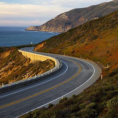

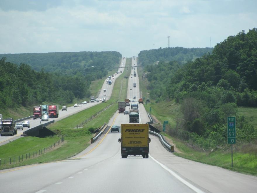
3 Introduction 3
4 Introduction 4
5 Introduction Deals with the dimensions and layout - alignment, sight distance and intersection Objective is to provide optimum efficiency with maximum safety at reasonable cost Main Design elements: Cross section elements Sight distance considerations Horizontal alignment Vertical alignment Intersection elements 5
6 Introduction Maximize the comfort and economy of facilities Efficiency in traffic operation Safety at reasonable cost Environmental impacts 6
7 Design Controls and Criteria Design Speed Topography Traffic factors Design hour volume and capacity Environmental and other factors 7
8 Design Controls and Criteria Design Speed o Most important factor o Affected by topography & road type o Influences all geometric elements of roads Topography o Plain; Rolling; Mountainous; Steep terrains o Speed and cross slope governs the design of elements Traffic Factors o Vehicular and Human Characteristics o Design vehicle speed, dimension, weight and acceleration, o Physical, mental and psychological characteristics driver Design hourly volume and capacity o Knowledge of Peak and off-peak hour volume Environmental and other factors o Aesthetics, landscaping, pollution, etc. 8
9 Terrain and Speed IRC
10 Highway Cross Sectional Elements Pavement Surface Characteristics o Friction Tyre and road surface speed, acceleration, sight distance, curve design o o o o o o o Pavement types cement concrete, bituminous, WBM Roughness of pavement Condition of pavement wet/dry, mud/oil spilled Tyre condition Speed of vehicles Load and tyre pressure Temperature, etc. Longitudinal friction ; Transverse
11 Highway Cross Sectional Elements Pavement Surface Characteristics o Unevenness Influences operating speed geometric standards Wear tear; accidents; operating cost; Low unevenness index cm/km (high speed highways) o Light Reflecting Characteristics Night visibility wet conditions Light coloured night condition (rainy); strain and glare (day) 11

12 Highway Cross Sectional Elements Cross Slope / Camber o Slope provided in the transverse direction to drain off the rain water Provided by raising the carriage way with respect to the edges Depends on type of the pavement surface & amount of rainfall IRC
13 Highway Cross Sectional Elements Width of Pavement or Carriageway o Depends on the width of traffic lane and number of lanes o Carriageway intended for one line of traffic movement is traffic lane o Lane width = vehicle width (2.44m )+ side clearance (0.625) IRC
 o Long bridges 1.2 to 1.5 m o Transition 1 in 15 to 1 in 20 o Urban roads: (absolute min width 1.2 m; desirable 5.0 m) o 1.")
14 Highway Cross Sectional Elements Traffic Separators / Medians o To prevent head on collision between vehicles moving in opposite directions on adjacent lanes o Pavement markings, medians, dividing islands, etc. o 5.0 m for rural highways (3.0 m land restriction) o Long bridges 1.2 to 1.5 m o Transition 1 in 15 to 1 in 20 o Urban roads: (absolute min width 1.2 m; desirable 5.0 m) o 1.2 m for pedestrian refuge o m for protection of vehicles making right turn o 9.0 to 12.0 m for protection of vehicles crossing at grade 14
15 Highway Cross Sectional Elements Kerb o Indicates the boundary between the pavement and shoulder Barrier, Semi-barrier, and Mountable o Barrier Built-up areas adjacent to footpaths with considerable pedestrian traffic o Semi-barrier periphery of the roadway where pedestrian traffic is light and a barrier could tend to reduce traffic capacity o Mountable Within the roadway at channelization schemes, medians, outer separators and raised medians on bridges 15


16 Cross Sectional Elements Kerb Source: IRC
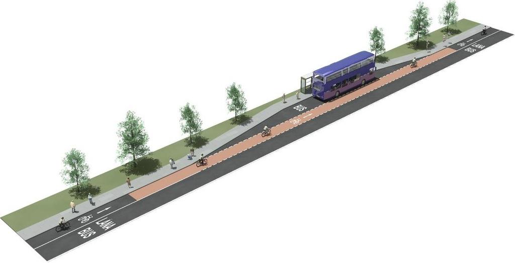
17 Highway Cross Sectional Elements o Road Margins Shoulders Emergency lane / service lanes (min 2.5 m width) Parking lanes for kerb parking (min 3.0 m width) Lay-byes to stop and clear off the carriageway Busbays 75m away from intersections Frontage roads access to properties Driveways connect commercial establishments Cycle tracks min 2 m width; 1 m for additional lane Footpath when vehicular and pedestrian volume is high (1.5 min ) 17


18 Highway Cross Sectional Elements 18
19 Highway Cross Sectional Elements o Width of roadway or formation sum of width of carriageway; separators (if provided) & shoulders IRC
20 Highway Cross Sectional Elements Right of Way Source: IRC

21 Sight Distance Sight Distance o Sight distance available from a point is the actual distance along the road surface which a driver from a specified height above the carriage way has visibility of stationary or moving objects o The length of road visible to the driver at any instance Should Satisfy: o Length of road visible ahead to stop the vehicle o Safely overtake at reasonable intervals o Control vehicle and avoid collision at uncontrolled intersection 21
22 Sight Distance Stopping Sight Distance The minimum sight distance available on a highway at any spot Depends on: o Features of the road ahead o Height of the driver s eye above the road surface (1.2 m) o Height of the object above the road surface (0.15 m) Stopping depends on: Total reaction time of the driver Speed of vehicle Efficiency of brakes Frictional resistance between the road and tyres Gradient, if any 22
23 Sight Distance Total Reaction Time o o o The time taken from the instant the object is visible to the driver to the instant the brakes are effectively applied Total reaction time = perception time + brake reaction time Total reaction time = 2.5 sec Speed of vehicle o Higher the speed, longer the stopping sight distance Efficiency of brakes o o 100% braking efficiency skidding Braking force should not exceed friction Frictional/skid Resistance o Depends on road and tyre o f = 0.35 to
24 Sight Distance Stopping Sight Distance 0.278Vt + V 2 254(f ± 0.01G) IRC
25 Sight Distance Overtaking Sight Distance The minimum distance open to the vision of the driver of a vehicle intending to overtake the slow moving vehicle with safety against the traffic in opposite direction 25
26 Sight Distance Overtaking Sight Distance Optimum condition is one in which the overtaking driver can follow the vehicle ahead for a short time while he assess his chances of overtaking o Assumptions: o The vehicle being overtaking is travelling at a uniform speed which is 16kmph less than the design speed of the road o The overtaking vehicle follows the vehicle ahead for a short while to perceive the clear road ahead o Overtaking is done by accelerating rapidly to the design speed and is considered completed when the vehicle returns to its own side of the road o Overtaking once began is finished in the face of an oncoming vehicle travelling at design speed in such a way that the latter arrives alongside the former just at the completion of maneuver 26
27 Sight Distance Overtaking Sight Distance o Overtaking maneuver 8 to 14 seconds o One third of the total time is spent following the vehicle to be overtaken o The opposing vehicle s travel distance in 2/3 of the total time is added. IRC
28 Sight Distance Intermediate Sight Distance o Sections of roads where the customary overtaking sight distance cannot be provided should be designed as far as possible for intermediate sight distance. o It is twice the normal safe stopping distance. IRC
")
29 Sight Distance Headlight Sight Distance o In valley curves roadway ahead is illuminated by vehicle headlights to a sufficient length enabling the vehicle to break stop (equal to SSD) 29
 and side")
30 Horizontal Alignment o Directional transition of the roadway in a horizontal plane o Relationship between design speed and curvature and on their joint relationships with superelevation (roadway banking) and side friction 30

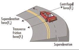
31 Horizontal Alignment Superelevation V2 e + f = 127R 31
32 Horizontal Alignment Superelevation o Plain and rolling terrain 7% o In snow bound areas 7% o In hilly areas not bound by snow 10% IRC
33 Horizontal Alignment o Radius of Horizontal Curve R = V 2 127(e + f) IRC

34 Horizontal Alignment Widening of Pavements on Horizontal Curve o When curves are not of large radius 34
35 Horizontal Alignment Widening of Pavements on Horizontal Curve o Extra Widening = Mechanical Widening + Psychological Widening W e = nl2 2R + V 9.5 R IRC

36 Horizontal Alignment Horizontal Transition Curve A transition curve has a radius which decreases from infinity at the tangent point to that of the circular curve. o Objectives: o To introduce the centrifugal force gradually o To steer the vehicle gradually and comfortably o To allow for gradual introduction of superelevation and extra widening o To improve aesthetic appearance 36
37 Horizontal Alignment Horizontal Transition Curve o Spiral curve: o Ideal transition o Calculation and implementation are easy 37
38 Horizontal Alignment o Length of Transition Curve i. Rate of change of centrifugal acceleration L s = V2 ; C = 80 CR 75 + V ii. Rate of change of Superelevation o For plain and rolling terrain L s = 2.7V2 R o For mountainous and steep terrain L s = V2 R 38
39 Horizontal Alignment IRC
40 Horizontal Alignment Setback distance o Distance from the road center line within which the obstructions should be cleared to ensure the needed visibility m = R (R n)cosθ 40

41 Vertical Alignment o The vertical alignment is the elevation or profile of the center line of the road to accommodate changes in grades o Consists of grades and vertical curves vehicle speed, acceleration, deceleration, SSD and comfort 41
42 Vertical Alignment Gradient the rate of rise or fall along the length of the road with respect to the horizontal (1 in x; n in 100) o Gradient types o Ruling gradient o Limiting gradient o Exceptional gradient o Minimum gradient 42
43 Vertical Alignment o Ruling Gradient The maximum gradient within which the designer attempts to design the vertical profile of the road (design gradient) o Limiting gradient where topography compels adopting steeper gradients than ruling gradients o Exceptional gradient steeper than limiting; not exceeding100 m at a stretch o Minimum gradient from drainage point of view; 1 in 500 in concrete drains 43
44 Vertical Alignment IRC
45 Vertical Alignment Grade Compensation o At horizontal curves, the gradients should be eased by an amount known as the grade compensation (reduction in gradient) o Grade compensation % = 30+R R ; max. = 75 R o Not necessary for grades flatter than 4% 45
46 Vertical Alignment Vertical Curve o At intersections of different grades to smoothen out the vertical profile Summit curves/crest curves Convexity upwards Valley curves/sag curves Concavity upwards 46
47 Vertical Alignment o Summit Curve o Governing design factor Sight Distance o Circular / Parabolic curves 47
48 Vertical Alignment o Length of Summit Curve for SSD i. When L>SSD L = NS 2 ( 2H + 2h) = NS ii. When L<SSD L = 2S 4.4 N 48
49 Vertical Alignment o Length of Summit Curve for OSD or ISD i. When L>OSD/ISD L = NS2 8H = NS2 9.6 ii. When L<OSD/ISD L = 2S 8H N = 2S 9.6 N 49
50 Vertical Alignment IRC
51 Vertical Alignment Valley Curve o Governing design factor comfort of passengers& availability of stopping sight distance under headlights of vehicle o Allowable rate of centrifugal acceleration influences the design (transition curves) 51
52 Vertical Alignment o Length of Valley Curve i. For comfort condition L = 0.38(NV 3 ) 1/2 ii. L > Headlight Sight Distance L = NS 2 ( S) iii. L < Headlight Sight Distance ( S) L = 2S N 52
53 References IRC codes 1. IRC: , geometric design standards for rural (non-urban) highways 2. IRC: , Geometric Design Standards for Urban Roads and Plains 3. IRC: , Recommended Practice for Sight Distance on Rural Highways 53
54 Thank You 54
Highway geometric design QUESTION PAPER
 QUESTION PAPER UNIT 1 1. Explain the design control and criteria which governs the design and highway. ( Dec 2011, june july 2011, June 2010, Dec 2010, Dec 2012) 2.Explain PCU value and factors affecting
3-13 UFC - GENERAL PROVISIONS AND GEOMETRIC DESIGN FOR ROADS, STREETS, WALKS, AND OPEN
 maintenance, and erosion. Stability is required to maintain the integrity of the pavement structure, and a slope stability analysis should be conducted for cuts and fills greater than 15 feet. For lower
HIGHWAY GEOMETRIC DESIGN
 SYLLABUS Subject Code: IA Marks: 25 No. of Lecture Hours/Week: 04 Exam Hours: 03 Total No. of Lecture Hours: 52 Exam Marks: 100 Unit - I INTRODUCTION: Elements Geometric Design control factors like topography-design
(HIGHWAY GEOMETRIC DESIGN -1)
") LECTURE HOUR-19 TE-1(10CV56) UNIT-3 (HIGHWAY GEOMETRIC DESIGN -1) Width of carriage way: Width of the carriage way or the width of the pavement depends on the width of the traffic lane and number of lanes.
LECTURE HOUR-19 TE-1(10CV56) UNIT-3 (HIGHWAY GEOMETRIC DESIGN -1) Width of carriage way: Width of the carriage way or the width of the pavement depends on the width of the traffic lane and number of lanes.
Alberta Infrastructure HIGHWAY GEOMETRIC DESIGN GUIDE AUGUST 1999
 Alberta Infrastructure HIGHWAY GEOMETRIC DESIGN GUIDE AUGUST 1999,1'(; A ACCELERATION Data on acceleration from stop D-29 Effects of grade D-35 Intersections D-97, D-99 Lanes D-97, F-5, F-7, F-15, F-21,
Figure 1: Graphical definitions of superelevation in terms for a two lane roadway.
 Iowa Department of Transportation Office of Design Superelevation 2A-2 Design Manual Chapter 2 Alignments Originally Issued: 12-31-97 Revised: 12-10-10 Superelevation is the banking of the roadway along
INDEX. Geometric Design Guide for Canadian Roads INDEX
 Acceleration lane, see Lanes, Acceleration Access, 8.1 Access Management and Functional Classification 8.2 Access Management by Design Classification 8.3 Access Configuration 8.4 Building Set-Back Guidelines
Chapter Twenty-eight SIGHT DISTANCE BUREAU OF LOCAL ROADS AND STREETS MANUAL
 Chapter Twenty-eight SIGHT DISTANCE BUREAU OF LOCAL ROADS AND STREETS MANUAL Jan 2006 SIGHT DISTANCE 28(i) Chapter Twenty-eight SIGHT DISTANCE Table of Contents Section Page 28-1 STOPPING SIGHT DISTANCE
October 2004 REVISIONS (2) SUPERELEVATION DEVELOPMENT 11.3(2)
 SUPERELEVATION DEVELOPMENT 11.3(2)") October 2004 REVISIONS (2) Chapter 11 HORIZONTAL ALIGNMENT SUPERELEVATION DEVELOPMENT 11.3(2) Chapter 12 VERTICAL ALIGNMENT VERTICAL CURVES PASSING SIGHT DISTANCE 12.5(2) VERTICAL CURVES STOPPING SIGHT
October 2004 REVISIONS (2) Chapter 11 HORIZONTAL ALIGNMENT SUPERELEVATION DEVELOPMENT 11.3(2) Chapter 12 VERTICAL ALIGNMENT VERTICAL CURVES PASSING SIGHT DISTANCE 12.5(2) VERTICAL CURVES STOPPING SIGHT
TABLE OF CONTENTS LIST OF FIGURES. Figure Title
 TABLE OF CONTENTS Table of Contents... 1 List of Figures... 1 Chapter Forty-two... 2 42-1.0 STOPPING SIGHT DISTANCE... 2 42-1.01 Theoretical Discussion...2 42-1.02 Passenger Car Stopping Sight Distance...
Road Markings. Lecture Notes in Transportation Systems Engineering. Prof. Tom V. Mathew
 Road Markings Lecture Notes in Transportation Systems Engineering Prof. Tom V. Mathew 1 Overview The essential purpose of road markings is to guide and control traffic on a highway. They supplement the
Dr. Naveed Anwar Executive Director, AIT Consulting Affiliated Faculty, Structural Engineering Director, ACECOMS
 Dr. Naveed Anwar Executive Director, AIT Consulting Affiliated Faculty, Structural Engineering Director, ACECOMS Overview Highway Functions and Classifications Highway Design Components Design Control
Road Markings. Lecture Notes in Transportation Systems Engineering. Prof. Tom V. Mathew. 1 Overview 1. 2 Classification 2
 Road Markings Lecture Notes in Transportation Systems Engineering Prof. Tom V. Mathew Contents 1 Overview 1 2 Classification 2 3 Longitudinal markings 2 3.1 Center line.....................................
1.3.4 CHARACTERISTICS OF CLASSIFICATIONS
 Geometric Design Guide for Canadian Roads 1.3.4 CHARACTERISTICS OF CLASSIFICATIONS The principal characteristics of each of the six groups of road classifications are described by the following figure
This Chapter sets forth the minimum design, technical criteria and specifications to be used in the preparation of all roadway plans.
 4.1 GENERAL This Chapter sets forth the minimum design, technical criteria and specifications to be used in the preparation of all roadway plans. These Roadway Standards are for new construction and modification
SIGHT DISTANCE GUIDELINES
 SIGHT DISTANCE GUIDELINES According to the 2011 AASHTO, 2011 MMUTCD, and Michigan Department of Transportation Guidelines PREPARED BY GEOMETRICS AND OPERATIONS UNIT TRAFFIC AND SAFETY April 22, 2015 Providing
Section 4 Basic Geometric Design Elements
 4.1 General Section 4 Basic Geometric Design Elements BDC07MR-01 Geometric highway design pertains to the visible features of the highway. It may be considered as the tailoring of the highway to the terrain,
By: CHE ROS ISMAIL PROF DR MOHD ROSLI HAININ DR HARYATI YAACOB DR SITTI ASMAH HASSAN JGP-FKA, UTM
 By: CHE ROS ISMAIL PROF DR MOHD ROSLI HAININ DR HARYATI YAACOB DR SITTI ASMAH HASSAN JGP-FKA, UTM CONTENT 1. INTRODUCTION 2. STAGES OF HIGHWAY DEVELOPMENT 3. ROAD CATEGORY/CLASSIFICATION 4. DESIGN STANDARDS
ENGINEERING STANDARD FOR GEOMETRIC DESIGN OF ROADS AND STREETS ORIGINAL EDITION MAR. 1996
 ENGINEERING STANDARD FOR GEOMETRIC DESIGN OF ROADS AND STREETS ORIGINAL EDITION MAR. 1996 This standard specification is reviewed and updated by the relevant technical committee on Dec. 2000(1) and July.
Vertical Alignment. Concepts of design & guidelines Computing elevations along vertical curves Designing vertical curves
 Vertical Alignment Concepts of design & guidelines Computing elevations along vertical curves Designing vertical curves Flat terrain You can select smooth horizontal alignment and smooth vertical alignment
Geometric design is the process whereby the layout of the road in the terrain is designed to meet the needs of the road users.
 CHAPTER 3: GEOMETRIC DESIGN OF HIGHWAYS Geometric design is the process whereby the layout of the road in the terrain is designed to meet the needs of the road users. 3.1 Appropriate Geometric Standards
200 Horizontal and Vertical Design. Table of Contents
 200 Horizontal and Vertical Design Table of Contents 201 Sight Distance... 2-1 201.1 General... 2-1 201.2 Stopping Sight Distance... 2-1 201.2.1 Horizontal Sight Distance... 2-2 201.2.2 Vertical Stopping
City of Roseville Section 13 Design Standards. _Bikeways January 2016 SECTION 13 BIKEWAYS
 SECTION 13 BIKEWAYS 13-1 GENERAL The City of Roseville bikeway standards are designed to insure that transportation and recreational bikeways are constructed in a manner that would provide a safe and comfortable
Roadway Vertical Alignments
 Roadway Vertical Alignments by Gregory J. Taylor, P.E. INTRODUCTION This course summarizes and highlights the design of vertical alignments for modern roads and highways. The contents of this document
How Might Connected Vehicles and Autonomous Vehicles Influence Geometric Design? October 10, 2017
 How Might Connected Vehicles and Autonomous Vehicles Influence Geometric Design? October 10, 2017 Overview Design Vehicle Design Driver Potential Geometric Impacts of Autonomous Vehicles Connected Vehicles
Driveway Design Criteria
 Design Manual Chapter 5 - Roadway Design 5L - Access Management 5L-4 Driveway Design Criteria A. General For efficient and safe operations, access drives and minor public street intersections can be improved
SECTION 12 ROAD MARKINGS AND DELINEATION
 SECTION 12 ROAD MARKINGS AND DELINEATION (Blank Page) MANUAL OF TRAFFIC SIGNS AND MARKINGS - Part III: Motorways and Expressways 12-1 12.1 GENERAL 12.1.1 INTRODUCTION The markings and delineation details
Chapter III Geometric design of Highways. Tewodros N.
 Chapter III Geometric design of Highways Tewodros N. www.tnigatu.wordpress.com tedynihe@gmail.com Introduction Appropriate Geometric Standards Design Controls and Criteria Design Class Sight Distance Design
CHECKLIST 6: EXISTING ROADS: ROAD SAFETY AUDIT
 CHECKLIST 6: EXISTING ROADS: ROAD SAFETY AUDIT 6.1 Road alignment and cross-section 6.1.1 Visibility; sight distance Is sight distance adequate for the speed of traffic using the route? Is adequate sight
Geometric Design Tables
 Design Manual Chapter 5 - Roadway Design 5C - Geometric Design Criteria 5C-1 Geometric Design Tables A. General The following sections present two sets of design criteria tables - Preferred Roadway Elements
CHECKLIST 2: PRELIMINARY DESIGN STAGE AUDIT
 CHECKLIST 2: PRELIMINARY DESIGN STAGE AUDIT 2.1 General topics 2.1.1 Changes since previous audit Do the conditions for which the scheme was originally designed still apply? (for example, no changes to
Roadway Horizontal Alignment
 Roadway Horizontal Alignment Course No: C04-034 Credit: 4 PDH Gregory J. Taylor, P.E. Continuing Education and Development, Inc. 9 Greyridge Farm Court Stony Point, NY 10980 P: (877) 322-5800 F: (877)
THE FUTURE OF THE TxDOT ROADWAY DESIGN MANUAL
 THE FUTURE OF THE TXDOT ROADWAY DESIGN MANUAL Kenneth Mora, P.E. (Design Division) 10/10/2017 Table of contents 1 2 Reduction in FHWA design controlling criteria Innovative Intersection Guidance 3-7 8-42
Roadway Horizontal Alignment Design
 Roadway Horizontal Alignment Design by Gregory J. Taylor, P.E. INTRODUCTION This course summarizes and highlights the design of horizontal alignments for modern roads and highways. The contents of this
TRAFFIC AND SAFETY NOTE 608A. Spacing for Commercial Drives and Streets. To Promote a Uniform Practice in Determining Access Spacing
 TRAFFIC AND SAFETY NOTE 608A SUBJECT: PURPOSE: Spacing for Commercial Drives and Streets To Promote a Uniform Practice in Determining Access Spacing COORDINATING UNIT: Geometric Design Unit INFORMATION:
MUTCD Part 6G: Type of Temporary Traffic Control Zone Activities
 MUTCD Part 6G: Type of Temporary Traffic Control Zone Activities 6G.01 Typical Applications Each temporary traffic control (TTC) zone is different. Many variables, such as location of work, highway type,
Geometric design deals with the dimensioning of the elements of highways, such
 CHAPTER 15 Geometric Design of Highway Facilities Geometric design deals with the dimensioning of the elements of highways, such as vertical and horizontal curves, cross sections, truck climbing lanes,
Sight Distance. The availability of sufficient sight distance for the driver to see ahead is critical to the design of a safe highway.
 Sigt Distance Te availability of sufficient sigt distance for te driver to see aead is critical to te design of a safe igway. Wat is sigt distance? Sigt distance is te lengt of igway visible to a driver.
GDOT Elements of Design. Course ID: GDOT PDH Credits
 GDOT Elements of Design Course ID: GDOT-06 3 PDH Credits Civil Engineer Educators LLC 1026 Timberwolf Lane Juneau, AK 99801 Email: support@civilpdh.com Chapter 4 Contents 4. ELEMENTS OF DESIGN 1 4.1. Sight
Roadway Vertical Alignments
 Course No: C04-031 Credit: 4 PDH Gregory J. Taylor, P.E. Continuing Education and Development, Inc. 9 Greyridge Farm Court Stony Point, NY 10980 P: (877) 322-5800 F: (877) 322-4774 info@cedengineering.com
SECTION 1A NEW JERSEY TURNPIKE GEOMETRIC DESIGN
 SECTION 1A NEW JERSEY TURNPIKE GEOMETRIC DESIGN Table of Contents Page No 1A.1 GENERAL...1 1A.1.1 DESIGN CONTROLS...1 1A.2 MAINLINE ROADWAYS...4 1A.2.1 ROADWAY DESIGNATION...4 1A.2.2 DESIGN SPEED...4 1A.2.3
LIST OF FIGURES Figure Title
 TABLE OF CONTENTS Table of Contents... 1 List of Figures... 2 44-1A Critical Length of Grade for Trucks... 3 44-1B Critical Length of Grade for Recreational Vehicles... 3 44-1C Measurement for Length of
General References Definitions. (1) Design Guidance. (2) Supporting Information
 Design Guidance. (2) Supporting Information") Chapter 1240 Turning Roadways 1240.01 General 1240.02 References 1240.03 Definitions 1240.04 Turning Roadway Widths 1240.05 Documentation 1240.01 General The roadway on a curve may need to be widened to
Chapter 1240 Turning Roadways 1240.01 General 1240.02 References 1240.03 Definitions 1240.04 Turning Roadway Widths 1240.05 Documentation 1240.01 General The roadway on a curve may need to be widened to
RAILWAY LEVEL CROSSING CHECKLIST Road Safety Review of Railway Crossings
 RAILWAY LEVEL CROSSING CHECKLIST Road Safety Review of Railway Crossings Location: Crossing No. Date of On-Site Inspection: (Day) / / (Night) / / Weather: CHECKLIST 5. - GENERAL TOPICS Level of control
10.0 CURB EXTENSIONS GUIDELINE
 10.0 CURB EXTENSIONS GUIDELINE Road Engineering Design Guidelines Version 1.0 March 2017 City of Toronto, Transportation Services City of Toronto Page 0 Background In early 2014, Transportation Services
Policy Statement. Objective. Context. References and Supporting Documentation
 Policy Statement Subject Placement of Distribution Poles Along Roads With Speed Limits Not Exceeding 70km/h Approved by Robert Rogerson Signature & Date Distribution Standards and Policy Manager Authorised
Issues Relating to the Geometric Design of Intersections Vergil G. Stover
 Introduction Issues Relating to the Geometric Design of Intersections Vergil G. Stover This paper presents five issues, or topics, that the author suggests be addressed in the design of intersections.
BI-DIRECTIONALS FREE-ACCESS
 BI-DIRECTIONALS FREE-ACCESS Dimensions may vary depending on design vehicle and turning movements. See GEO-650-Series for addtional details. SPECIAL Special situations, i.e., See Notes 4 & 5 wide streets,
WYDOT DESIGN GUIDES. Guide for. Non-NHS State Highways
 WYDOT DESIGN GUIDES Guide for Non-NHS State Highways 2014 GUIDE FOR Non-NATIONAL HIGHWAY SYSTEM (Non-NHS) STATE HIGHWAYS PRESERVATION REHABILITATION RECONSTRUCTION INTRODUCTION This Guide is directed to
11 CHECKLISTS Master Checklists All Stages CHECKLIST 1 FEASIBILITY STAGE AUDIT
 11 CHECKLISTS 11.1 Master Checklists All Stages CHECKLIST 1 FEASIBILITY STAGE AUDIT 1.1 General topics 1. Scope of project; function; traffic mix 2. Type and degree of access to property and developments
Road Safety Facilities Implemented in Japan
 Road Safety Facilities Implemented in Japan 1 Road Safety Facilities 1.Guard Fence 2.Road Lighting 3.Other Road Safety Facilities 2 Road Safety Facilities 1.Guard Fence 2.Road Lighting 3.Other Road Safety
SECTION 12 ROAD MARKINGS AND DELINEATION
 SECTION 12 20 June 2009 Part 3: Motorways and Expressways CONTENTS Reference Page Page Number Date SECTION 12: MARKINGS AND DELINEATION 12.1 GENERAL... 12-1 June 2009 12.1.1 INTRODUCTION... 12-1 June 2009
Figure 3B-1. Examples of Two-Lane, Two-Way Marking Applications
 Figure 3B-1. Examples of Two-Lane, Two-Way Marking Applications A - Typical two-lane, two-way marking with passing permitted in both directions B - Typical two-lane, two-way marking with no-passing zones
WYDOT DESIGN GUIDES. Guide for. NHS Arterial (Non-Interstate)
") WYDOT DESIGN GUIDES Guide for NHS Arterial (Non-Interstate) 2014 GUIDE FOR NATIONAL HIGHWAY SYSTEM (NHS) HIGHWAYS (NHS ARTERIALS, Non-Interstate) PRESERVATION REHABILITATION RECONSTRUCTION INTRODUCTION
WYDOT DESIGN GUIDES Guide for NHS Arterial (Non-Interstate) 2014 GUIDE FOR NATIONAL HIGHWAY SYSTEM (NHS) HIGHWAYS (NHS ARTERIALS, Non-Interstate) PRESERVATION REHABILITATION RECONSTRUCTION INTRODUCTION
* BLACK TRIANGLES Correct Answer. * RED TRIANGLES Red / blue circles. * BLUE RECTANGLES Explanation
 1 YOU MUST OBEY SIGNS GIVING ORDERS. THESE SIGNS ARE MOSTLY IN * BLACK TRIANGLES Correct Answer * RED TRIANGLES Red / blue circles. * BLUE RECTANGLES Explanation * RED / BLUE CIRCLES Traffic signs can
CHAPTER 1 STANDARD PRACTICES
 CHAPTER 1 STANDARD PRACTICES OBJECTIVES 1) Functions and Limitations 2) Standardization of Application 3) Materials 4) Colors 5) Widths and Patterns of Longitudinal Pavement Marking Lines 6) General Principles
INTERSECTIONS AT GRADE INTERSECTIONS
 INTERSECTIONS 1 AT GRADE INTERSECTIONS INTERSECTIONS INTERSECTIONS = INTERRUPTED FACILITIES Definitions and key elements An intersection is defined as an area where two or more roadways join or cross.
Guide to Road Design Part 3: Geometric Design Session I 18 October 2016
 Guide to Road Design Part 3: Geometric Design Session I 18 October 2016 Today s moderator Angela Racz Online Training Coordinator Knowledge Transfer - ARRB Group P: +61 3 9881 1694 E: training@arrb.com.au
Intersection Safety 6/7/2015 INTERSECTIONS. Five basic elements should be considered in intersection design. Intersection Safety (continued)
") Intersection Safety S. M. SOHEL MAHMUD Assistant Professor Accident Research Institute (ARI), Bangladesh University of Engineering and Technology (BUET) Dhaka-1000, Bangladesh 1 Outline of the Presentation
Intersection Safety S. M. SOHEL MAHMUD Assistant Professor Accident Research Institute (ARI), Bangladesh University of Engineering and Technology (BUET) Dhaka-1000, Bangladesh 1 Outline of the Presentation
Access Location, Spacing, Turn Lanes, and Medians
 Design Manual Chapter 5 - Roadway Design 5L - Access Management 5L-3 Access Location, Spacing, Turn Lanes, and Medians This section addresses access location, spacing, turn lane and median needs, including
Introduction Methodology Study area and data collection Results and recommendation Conclusion References
 Introduction Methodology Study area and data collection Results and recommendation Conclusion References It is formal procedure for assessing accident potential and safety performance in the provision
To position power poles a safe distance from the road to minimise the likelihood of being accidentally hit by vehicles.
 Policy Statement Subject Placement of Rigid Distribution Poles Along Roads With Speed Limits Exceeding 70KM/H Approved by Robert Rogerson Signature & Date Distribution Standards and Policy Manager Authorised
IMPLEMENTATION. PEDESTRIAN USERS (Continued /) Building Frontages: A: Stair Applications. Geometry (Accessed from the Sidewalk) Refer to A:
 Building Frontages: A: Stair Applications. Geometry (Accessed from the Sidewalk) Refer to A:") A: Stair Applications Building Frontages: Geometry (Accessed from the Sidewalk) Refer to A: Ramps should be provided for disabled users at 1:12 (8.3%) gradient. Ramp rises should be stepped at 400mm intervals.
A: Stair Applications Building Frontages: Geometry (Accessed from the Sidewalk) Refer to A: Ramps should be provided for disabled users at 1:12 (8.3%) gradient. Ramp rises should be stepped at 400mm intervals.
PLACEMENT OF SIGNS RECOMMENDED PRACTICES SUB-SECTION
 Page 1 of 6 RECOMMENDED PRACTICES PART SECTION SUB-SECTION HIGHWAY SIGNS GENERAL General Proper positioning of signs is an important element in the overall control of traffic within a roadway network.
Roadway Design Manual
 Roadway Design Manual Manual Notice Archive by Texas Department of Transportation (512) 302-2453 all rights reserved Manual Notice 2009-1 From: Manual: Mark A. Marek, P.E Roadway Design Manual Effective
3.0 ROAD PLANNING, DESIGN AND CONSTRUCTION
 3-1 3.0 ROAD PLANNING, DESIGN AND CONSTRUCTION 3.1 AIM Councils aim under its Transport Infrastructure Program is to efficiently and effectively provide and manage transport infrastructure to ensure safe
Access Management Standards
 Access Management Standards Section 1: Application of Access Standards This chapter describes the Department's access management standards for access connections on the county roadway system. The standards
JUNE, 2000 ROAD DESIGN MANUAL 5-0(1) CHAPTER 5 AT-GRADE INTERSECTIONS
 CHAPTER 5 AT-GRADE INTERSECTIONS") JUNE, 2000 ROAD DESIGN MANUAL 5-0(1) CHAPTER 5 AT-GRADE INTERSECTIONS 5-1.0 INTRODUCTION 5-1.01 Definition 5-1.02 Policy 5-1.03 Design Considerations 5-1.04 Vehicle Characteristics 5-1.04.01 Turning Radii
JUNE, 2000 ROAD DESIGN MANUAL 5-0(1) CHAPTER 5 AT-GRADE INTERSECTIONS 5-1.0 INTRODUCTION 5-1.01 Definition 5-1.02 Policy 5-1.03 Design Considerations 5-1.04 Vehicle Characteristics 5-1.04.01 Turning Radii
LIST OF TABLES LIST OF FIGURES
 TABLE OF CONTENTS 6 INTERSECTION DESIGN....................................................... 6-1 6.1 INTRODUCTION...................................................... 6-1 6.2 DESIGN PRINCIPLES..................................................
Basic Road Design. If you don't know where you are going, any road will get you there. Lewis Carroll
 Basic Road Design If you don't know where you are going, any road will get you there. Lewis Carroll Road Design Horizontal alignment of a road defines its location and orientation in plan view. Vertical
IMPLEMENTATION. PEDESTRIAN USERS (Continued /) A: Class 2 Pedestrian / Cycle Ways. Pedestrian and Cycle Ways:
 A: Class 2 Pedestrian / Cycle Ways. Pedestrian and Cycle Ways:") A: Class 2 Pedestrian / Cycle Ways PLAN VIEW Pedestrian and Cycle Ways: Layout and Geometry (Refer to A): Walkways and cycle to be provided adjacent to all Class 2 Roads (these facilities should always
A: Class 2 Pedestrian / Cycle Ways PLAN VIEW Pedestrian and Cycle Ways: Layout and Geometry (Refer to A): Walkways and cycle to be provided adjacent to all Class 2 Roads (these facilities should always
Progress Report on the Design and Planning of an Infrastructure Improvement Project for the Sunnyside TIF District (Phase II)
") Presentation to the CNRC Board of Directors Regular Meeting March 11, 2015 1 Agenda Preferred Alternate Refinement for University Avenue, 3rd Street, and Beverly Avenue Intersection Improvements validate
Presentation to the CNRC Board of Directors Regular Meeting March 11, 2015 1 Agenda Preferred Alternate Refinement for University Avenue, 3rd Street, and Beverly Avenue Intersection Improvements validate
SECTION 3 STREET DESIGN
 3.01 GENERAL SECTION 3 STREET DESIGN For purposes of geometric and structural design, streets shall be classified according to the following table. The City Engineer will determine the class of all proposed
CHAPTER 16 PEDESTRIAN FACILITIES DESIGN AND TECHNICAL CRITERIA TABLE OF CONTENTS
 CHAPTER 16 PEDESTRIAN FACILITIES DESIGN AND TECHNICAL CRITERIA TABLE OF CONTENTS Section Title Page 16.1 General... 16-1 16.1.1 AASHTO Reference... 16-1 16.1.2 ADA Requirements... 16-1 16.2 Sidewalks...
Chapter 5 5. INTERSECTIONS 5.1. INTRODUCTION
 Chapter 5 5. INTERSECTIONS 5.1. INTRODUCTION Intersections are the physical component of the roadways where two highways intersect. They are the most complex element of roadways, since it requires more
Transportation Knowledge
 FE REVIEW COURSE SPRING 2017 Transportation Engineering 4/26/2017 Transportation Knowledge 8-12 problems Traffic safety Traffic capacity Traffic flow theory Traffic control devices Transportation planning
Designing and Benchmarking Mine Roads for Safe and Efficient Haulage. Roger Thompson Alex Visser
 Designing and Benchmarking Mine Roads for Safe and Efficient Haulage Roger Thompson Alex Visser Departments of Mining and Civil & Bio-systems Engineering University of Pretoria, South Africa Aim of Presentation
Design of Suburban Highways
 Design of Suburban Highways by David L. Heavey, P.E. TABLE OF CONTENTS Introduction...3 Design Speed, Posted Speed and Operating Speed...4 Median Types...5 Raised Medians...9 Common Suburban Roadway Typical
Chapter 5 Shared-Use Paths
 Chapter 5: 5-1.0 Introduction Shared-Use Paths This chapter provides guidelines for design of bicycle transportation facilities that are separated from the roadway. In most cases, a path separated from
FOR HISTORICAL REFERENCE ONLY
 To: From: Subject: Electronic Distribution Recipients MINNESOTA DEPARTMENT OF TRANSPORTATION Engineering Services Division Technical Memorandum No. 12-14-B-03 December 18, 2012 Jon M. Chiglo, P.E. Division
STATE HIGHWAY GEOMETRIC DESIGN MANUAL APPENDIX A: DESIGN CHECKLIST
 STATE HIGHWAY GEOMETRIC DESIGN MANUAL A - 1 Appendix A: Design Checklist for the Development of Geometric Plans (For use in the Planning and Design of State Highway Improvement Projects) NOTES: 1. Design
Shared Use Path Design
 12B-2 Design Manual Chapter 12 - Sidewalks and Bicycle Facilities 12B - Bicycle Facilities Shared Use Path Design A. Accessible Shared Use Path Design 1. General: Applicable portions from the following
Subject: Use of Pull-off Areas in Work Zones Page: 1 of 13. Brief Description: Guidance for the use and placement of pull-off area in work zones.
 6 - G2 Subject: Use of Pull-off Areas in Work Zones Page: 1 of 13 MdMUTCD REF. NO. None Date Issued: 09/09 Effective Date: 09/09 Brief Description: Guidance for the use and placement of pull-off area in
Off-Road Facilities Part 1: Shared Use Path Design
 Off-Road Facilities Part 1: Shared Use Path Design Presentation by: Eric Mongelli, P.E. Tom Huber October 9, 2012 FOLLOW THE CONVERSATION ON TWITTER Toole Design Group is live tweeting this webinar @tooledesign
Safety Impacts: Presentation Overview
 Safety Impacts: Presentation Overview The #1 Theme How Access Management Improves Safety Conflict Points The Science of Access Management By Treatment Studies Themes for Texas Access Management Improve
15. HIGHWAY IMPROVEMENT GUIDES AND POLICIES
 15. HIGHWAY IMPROVEMENT GUIDES AND POLICIES Introduction The design of roadways must ensure the safe and efficient movement of vehicles. In order to accomplish this objective, design should be based on
An International Experience on the Safety Performance of 2+1 cross-section. Basil Psarianos Nat l Techn. Univ. Athens, Greece
 An International Experience on the Safety Performance of 2+1 cross-section Basil Psarianos Nat l Techn. Univ. Athens, Greece bpsarian@mail.ntua.gr What is a 2+1 cross-section? It s a 3 lane rural road
Introduction to Transportation Engineering. Discussion of Stopping and Passing Distances
 Introduction to Transportation Engineering Discussion of Stopping and Passing Distances Dr. Antonio A. Trani Professor of Civil and Environmental Engineering Virginia Polytechnic Institute and State University
Recommended Roadway Plan Section 2 - Land Development and Roadway Access
 Recommended Roadway Plan Section 2 - Land Development and Roadway Access SECTION 2 Land Development and Roadway Access 2.1 Land Use and Access Management The Federal Highway Administration (FHWA) defines
10 SHERFORD Town Code
 Key Fixes (Ref: Masterplan Book, section 4a. Land Use Budget and Key Fixes ) The Town Plan designs and allocates buildings, streets and spaces as accurately as possible in the understandable absence of
Module 5: Navigating Roadways
 Module 5: Navigating Roadways Topic 1: Intersections 1. One out of FATAL crashes occur at intersections. 2. Label the intersection warning signs: 3. When possible, begin searching seconds ahead of the
General Design Factors
 Chapter 3: 3-1.0 Introduction General Design Factors Mn/DOT s goals include encouraging and accommodating safe bicycling. From a design perspective, these goals are achieved by first having an understanding
LECTURE NOTE COURSE CODE- BCE 305 TRANSPORTATION ENGINEERING-I
 LECTURE NOTE COURSE CODE- BCE 305 TRANSPORTATION ENGINEERING-I SYLLABUS Module-I Transportation by roads, railways, water ways & air ways their importance& limitation. Road development & planning in India.
MUNICIPALITY OF ANCHORAGE Traffic Department MEMORANDUM
 MUNICIPALITY OF ANCHORAGE DATE: MEMORANDUM TO: FROM: SUBJECT: Anchorage Contractors, Builders, Designers, and Land Owners Robert E. Kniefel, P.E., Municipal Traffic Engineer Municipal Driveway Standards
DEFINITIONS Activity Area - Advance Warning Area Advance Warning Sign Spacing Advisory Speed Approach Sight Distance Attended Work Space
 DEFINITIONS Activity Area - that part of a TTC zone activity area where the work actually takes place. It consists of the work space, traffic space and one or more buffer spaces. Advance Warning Area -
APPENDIX A TWO-LANE RURAL ROADS ELEMENTS OF DESIGN CREST VERTICAL CURVES
 APPENDIX A TWO-LANE RURAL ROADS ELEMENTS OF DESIGN CREST VERTICAL CURVES 1. Two-lane Rural Roads 1.1 Introduction The definition of rural area can be derived from the definition of urban areas. Officially,
UP GRADATION OF GEOMETRIC DESIGN OF SH-131(CH.
 UP GRADATION OF GEOMETRIC DESIGN OF SH-131(CH. Up Gradation of Geometric Design of Sh-131(Ch. 9.35km-15.575km) Using Mxroad Software-A Case Anil, 9.35KM-15.575KM) Kadam Shubham, Journal USING Impact Factor
SUBJECT: Chapters 2 and 3 (Sight Distance), 5, and 8 (Drainage Structures and Castings)
, 5, and 8 (Drainage Structures and Castings)") DISTRIBUTION: Electronic Recipients List MINNESOTA DEPARTMENT OF TRANSPORTATION DEVELOPED BY: Design Standards Unit ISSUED BY: Office of Project Management and Technical Support TRANSMITTAL LETTER NO.
DISTRIBUTION: Electronic Recipients List MINNESOTA DEPARTMENT OF TRANSPORTATION DEVELOPED BY: Design Standards Unit ISSUED BY: Office of Project Management and Technical Support TRANSMITTAL LETTER NO.
Footpath design. A guide to creating footpaths that are safe, comfortable, and easy to use
 Footpath design A guide to creating footpaths that are safe, comfortable, and easy to use November 2013 Contents Introduction / 1 Zoning system / 2 Width / 4 Height / 5 Surface / 5 Footpath elements /
The City of Sault Ste. Marie Cycling Master Plan
 4.0 DESIGN GUIDELINES - Development This section provides direction to those who will be constructing trails in the future. The contents are technical, providing facility types and locations, construction