Think Safety, Think Safesite O&M - MOBILE MAN ANCHOR
|
|
|
- Meredith Phelps
- 5 years ago
- Views:
Transcription

1 Think Safety, Think Safesite O&M - MOBILE MAN ANCHOR


2 Safesite Mobile Man Anchor INTRODUCTION The CE Approved Mobile Man Anchor is an item of Personal Protective Equipment (PPE) which has been specifically designed to provide short term safety for low frequency operations where guardrails are not provided. The unit is ideal for short term maintenance operations to flat roofs or to the plant and equipment installed at roof level such as AC units, telecommunications equipment etc. Safesite s Mobile Man Anchor is extremely compact, portable, easily assembled and features a unique design incorporating a shock absorber which reduces the total weight of the unit, making the product more user friendly. The Mobile Man Anchor has been designed to be used with an approved shock absorbing rope grab and rope and full body harness to provide safe access at all times. The unit is fully galvanised to BS EN ISO 1461: Hot Dip Galvanised Coatings Specification and test methods. The Anchor Weights are supplied with suction cup rubber boots. These protect the roof membrane, increase friction resistance and enable the anchor to be used on all roof membranes, even in wet weather. The Mobile Man Anchor fully complies with BS EN 795: Protection against falls from height - Anchor devices - Requirements and testing. The unit has also been designed to ensure compliance with the following Regulations: Construction (Design & Management) Regulations Work at Height Regulations Construction (Health, Safety & Welfare) Regulations Workplace (Health, Safety & Welfare) Regulations Manual Handling Operations Regulations BUILDING HEIGHT & SAFE WORKING It is essential that a risk assessment is carried out by a competent person to ensure that the product is used safely. Part of the assessment will consider the building s height and the combination of PPE to be used in conjunction with the Safesite Mobile Man Anchor. Safesite recommends that, as far as reasonably practicable, the Mobile Man Anchor should be used as a fall restraint solution rather than fall arrest. When used for fall restraint, the Mobile Man Anchor must be used in conjunction with PPE that prevents the operative from reaching the leading edge. The Mobile Man Anchor should then be positioned so that the rope remains taught as the user approaches the edge. If the above is not possible and a fall arrest solution is required then a sufficiently detailed risk assessment, method statement and rescue policy must be produced by a competent person. Care must also be taken to use the correct combination of PPE to minimize the distance & consequence of a potential fall. Generally the length of the shock absorbing rope grab device should not exceed the height of the building in order to avoid the possibility of the pendulum effect. To prevent this, the Mobile Man Anchor should be placed perpendicular to the leading edge where the operative is likely to be working. The rope grab line should remain taught at all times when working at the leading edge.


3 No part of the Mobile Man Anchor should be placed closer than 2.5m from the nearest roof edge. The unit should not be placed on any surfaces affected by ice, grease or similar slippery conditions which may impair the performance of the unit. ROOF PITCH & SAFE WORKING The Mobile Man Anchor can be used on any flat roof or industrial steel cladded pitched roof up to 15 pitch provided that the unit is positioned on the opposite pitch to where the operative intends to work. When placed on a roof slope, the Mobile Man Anchor must be at least 2.5m from the ridge. In all cases, the roof structure must be capable of taking the load of the Mobile Man Anchor (250kg) combined with the weight of the operative, plus any additional equipment required. LEGAL REQUIREMENTS The Work at Height Regulations 2005 require that the employer/ building owner has a rescue plan and policy in place for all fall arrest systems. (See pages 94-99) TESTING & CE APPROVAL Safesite s Mobile Man Anchor has been extensively tested by SATRA to BS EN 795: Protection against falls from a height - Anchor devices - Requirements and testing. The unit was tested on the following roof surfaces and has been awarded CE Approval accordingly. Single Ply Membrane HT Mineral Grade Felt Swept Stone Chippings Paving Slabs Asphalt Steel Cladding EN 795 Test Procedure The test involved a 100kg weight freefalling a distance of 2.5m to reach a maximum velocity. The Mobile Man Anchor then had to bring this force to a complete rest within a horizontal movement not exceeding 1.0m. This was achieved via the extension of the shock absorber coupled with horizontal movement of the complete unit. This test was then successfully duplicated using a 120kg weight. Full independent test documentation is available upon request. In addition to the above testing, the Mobile Man Anchor has also been tested with a shock absorbing rope grab device with 14mm twisted rope connected to the shock absorber of the Mobile Man Anchor over steel & concrete sharp edges, thus representing on site usage of the system. The same test load as BS EN 795 was applied to the system. This testing successfully demonstrate d the compatibility of the shock absorbing rope grab device with 14mm twisted rope when used horizontally in combination with a Safesite Mobile Man Anchor over sharp edges. EN 795 Review This standard has recently been reviewed. As a consequence the 100kg test weight remains unchanged, but the free fall distance has been changed from 2.5m to 1.5m. Once this dynamic load has been applied an additional 100kg static load is then applied, thus representing an extreme rescue situation where a rescuer has no choice but to abseil to the casualty. LINKED MOBILE MAN ANCHOR SYSTEMS See Fall Arrest and Restraint Linked System.

4 Safesite Mobile Man Anchor Specification 950mm 50mm MOBILE MAN ANCHOR CROSS FRAME - MMA 001 This unit is the heart of the system and provides the means of connecting the man anchor weights to the shock absorber anchorage point. Material : galvanised steel to BS EN ISO Net weight : 13.6kg. 250mm 300mm MOBILE MAN ANCHOR WEIGHT - MMA 002 This component is one of twelve that are used to provide the overall weight of the system. Material : galvanised steel to BS EN ISO Net weight : 19kg. 61mm 140mm Ø12mm 96mm 152mm 92mm L-BOLT - MMA 005 & HANDLE - MMA 006 The L-Bolt provides the means of securing the components to the system. Material : stainless steel A2-50 grade. Net weight : 0.13kg. The Handle provides the attachment of the shock absorber to the Mobile Man Anchor Cross Frame. Material : stainless steel A2-50. Net weight : 0.285kg. 50mm 515mm MOBILE MAN ANCHOR EXTENSION ARM - MMA 003 This unit is utilised to connect the second and third weight of each arm to the cross frame. Material : galvanised steel to BS EN ISO Net weight : 2.5kg. SHOCK ABSORBER - MMA 007 This component absorbs the shock loading should an operative fall whilst connected to the Mobile Man Anchor. The component is designed to be disposed of should it be activated. Material : bright zinc plated steel. Net weight : 0.85kg. 307mm 150mm 100mm 85mm 257mm LINKED MOBILE MAN ANCHOR - SUPPORT POST - STIC10 This item can be fitted to the standard cross frame. This arrangement links a series of Mobile Man Anchor utilising the KeeLine system. This provides a fall restraint/arrest system that has the advantage of being free standing as opposed to being traditionally fixed to the structure. Mobile Man Anchor centres 10m. Material : Galvanised steel to BS EN ISO Net weight : 1.5kg. RUBBER BOOTS - MMA REP BOOTS Set of 12 replacement rubber boots for MMA 002. Material : Natural rubber Net weight : 0.88kg.
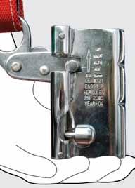
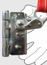
5 Complies with BS EN 795 Class E Anchorage Devices MOBILE MAN ANCHOR USER INSTRUCTIONS Please ensure all operatives have read fully and understood all instructions for the safety equipment before using and completed a comprehensive risk assessment for each roof and/or roof membrane. Only one person to be connected at any one time. Recommended maximum weight of person 136kg. On a flat roof make sure that the Mobile Man Anchor will be used at least 2.5m from the edge of the roof. See diagram. See Minimum Height Requirements section. When used on steel cladded roofs up to 15 pitch always place the Mobile Man Anchor on the opposite pitch to the one you are working on. Always position the Mobile Man Anchor a minimum of 2.5m from the ridge on the opposite pitch. When working on the verge detail remember to position the Mobile Man Anchor at least 2.5m from the verge and only work opposite the Mobile Man Anchor in order to avoid the pendulum effect down the façade of the building. Sweep any loose materials from the surface of the roof covering where the Mobile Man Anchor will be placed. (Do not use on icy, greasy or any slippery surfaces that may impair the Mobile Man Anchor s performance.) Ensure that the rubber boots are in place and in good condition before using. Slide 1 Mobile Man Anchor Weight onto each of the cross frame legs and tighten the locking handles in a clockwise direction. See diagram for exact layout. Slide 1 Extension Arm onto each of the cross frame legs and tighten the locking handles in a clockwise direction. See diagram for exact layout. Slide a further 2 Weights onto each of the Extension Arms and tighten the locking handles in a clockwise direction. See diagram for exact layout. Connect karabiner (or similar approved clip) of the shock absorbing rope grab device (or fixed length lanyard) only to the loose end of the spring shock absorber on the Mobile Man Anchor. Never connect to any other part of the Mobile Man Anchor. Check the spring shock absorber is in good condition and that it is not stretched or damaged in any way. If the spring is elongated do not use the unit and return the whole assembly to Safesite Limited for repair / replacement. All operatives must read & fully understand all PPE instructions before using with the Mobile Man Anchor. Once the operative is wearing the harness connect the karabiner on the end of the shock absorbing rope grab device (or fixed length lanyard) to either of the chest or rear D-Rings of the harness. Make sure all connections are fixed correctly and that the system has been assembled correctly. The system is now ready for use. If you are in any doubt please contact Safesite s Technical Department on m 2.5m Minimum 15º Maximum 2.5m Minimum FLAT ROOF SAFE WORKING PRACTICE PITCHED ROOF SAFE WORKING PRACTICE ASSEMBLY OF MOBILE MAN ANCHOR CE BS EN 795 TOTAL WEIGHT OF COMPLETE ASSEMBLY 250kg. CONNECT THE SHOCK ABSORBING ROPE GRAB DEVICE (or fixed length lanyard) TO THE MOBILE MAN ANCHOR SHOCK ABSORBER ONLY See Minimum Height Requirements Section

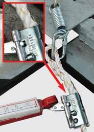
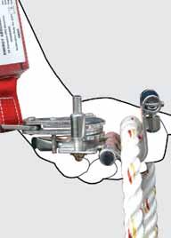
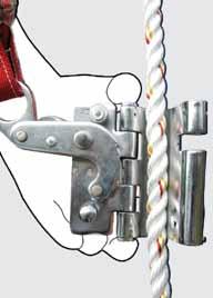
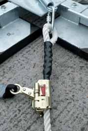
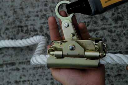
6 Safesite Mobile Man Anchor and 14mm Rope Grab Operation The rope grab has to be opened to position the rope correctly. Open the rope grab device as follows:- Pull lever 2 down and push fully into the opening to disengage the pressure pin 3. The device will now open. (See a, b & c) Note: Ensure the rope grab is attached to the rope with arrow 1 pointing towards the Safesite Mobile Man Anchor. Place the rope in the device, ensuring arrow 1 is still pointing towards the Mobile Man Anchor. Close the device and it will automatically lock. (The lever will return to the original position). Check that the device slides freely on the rope when the eyelet 5 is pulled downwards. (See d, e & f) Attach the end of the rope to the Safesite Mobile Man Anchor spring/shock absorber using an EN 362 connector. (See g) The device can be used in either AUTOMATIC mode for vertical access use (Ladder) or MANUAL mode, when using along horizontal surfaces or inclined planes (roof). MANUAL mode is the recommended option when using in conjunction with the Safesite Mobile Man Anchor on flat or inclined roofs. When using in MANUAL mode, the selector 4 is down. Remove selector 4 from the securing pin 8 and bring it to rest against the end stop 6. This will ensure that it can only slide along the rope by manually operating the pincher arm 7 (See h & i) In AUTOMATIC mode, selector 4 is up. In this position the device follows the user as they move upwards or downwards and, in the case of a fall, instantly locks on the rope. ( See j).


7 a. b. c. d. e. f. g. h. i. j.
 Push the leaver marked Push 2 hold this down and slide the leaver 3 in a downwards")
 Note: Ensure the rope grab is attached to the rope with arrow 9 pointing towards the Safesite Mobile Man Anchor (anchorage point).")
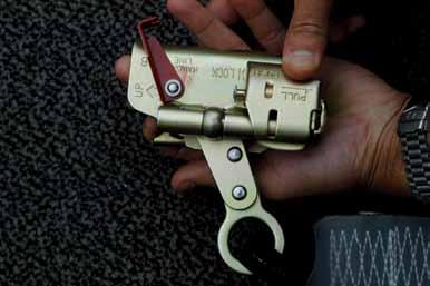
8 Safesite Mobile Man Anchor and 16mm Rope Grab Operation The rope grab has to be opened to position the rope correctly. Open the rope grab device as follows:- Holding the rope grab, move the Safety Catch 1 towards the up arrow (See a) Push the leaver marked Push 2 hold this down and slide the leaver 3 in a downwards direction and engage it against the holding lug (See b & c). The device will now open. (See d top) Note: Ensure the rope grab is attached to the rope with arrow 9 pointing towards the Safesite Mobile Man Anchor (anchorage point) Place the rope in the rope grab (See d bottom), ensuring arrow 9 is still pointing towards the Mobile Man Anchor. Close the device and push the leaver 2. The rope grab will automatically close (See e). Re-engage the safety catch 1 (See f). Check that the rope grab slides freely on the rope when the eyelet 5 is pulled upwards. Attach the end of the rope to the Safesite Mobile Man Anchor spring/shock absorber using an EN 362 connector. (See g) The device can be used in either AUTOMATIC mode for vertical access use (Ladder) or MANUAL mode, when using along horizontal surfaces or inclined plane (roof). When using in MANUAL mode, the selector 4 is down. Remove selector 4 from the securing lug 8 and bring it to rest against the end stop 6. This will ensure that it can only slide along the rope by manually operating the pincher arm 7 (See h & i) In AUTOMATIC mode, selector 4 is up and engaged against the lug. In this position the device follows the user as they move upwards and downwards (See j).


9 a. b. c. d. e. f. g. h. i. j.
10 Safesite Mobile Man Anchor Recertification Periodic inspections by a competent person are required under Regulation 5 of the Workplace (Health Safety & Welfare) Regulations, BS EN 365 & BS The frequency will depend upon environment, location and utilisation, but should be at least every 12 months. Walk & visually inspect the complete system installation (where applicable) in relation to the general client s needs. Establish if any modifications, additional products are required to reflect any refurbishment or additional plant and equipment that has been installed and requires access. Check installation configuration (where applicable) is complete as per the original installation drawing/plan. Ensure the system has not been modified/tampered with by unauthorised persons. DETAILED COMPONENT INSPECTION:- Cross Frame (1). Check arms on cross for distortion or dents. Ensure that this does not affect the fitting of the weight or extension arm. Check metal plate for distortion or cracks. Check handle is securely in place. Check shock absorber for any signs of pulling - no elongation. Check for any general corrosion. Extension Arms (4). Check arms for distortion along length. Ensure that any dents at widest end do not affect the connection to the cross frame. Look for signs of cracks in metal - especially around any bruised areas. Check for any general corrosion. Counter weights (12) Check all rubber boots on the weights are in good order - no tears or rubber missing. Check L-bolts are still present and in good order to lock and unlock (ease of movement). ENSURE GREASING IS CARRIED OUT ANNUALLY. Check box section and handle for dents, cracking etc. Make sure arm slides through easily and is secure when L-bolts are tightened. Check for any general corrosion. Any galvanised components showing signs of corrosion, wire brush thoroughly and apply galvanised spray / paint as appropriate. If rusted significantly take digital photographs and include in the inspection report. Once all other inspection points are completed, check that the whole device is fixed securely in position with no obvious distortions in balance. Check system plaque (where applicable) position & mark up to reflect date of the next required inspection. Establish if additional plaques are required due to any refurbishment works. In the event of a fall the Mobile Man Anchor MUST be returned to the manufacturer for re-testing. When used in anger the shock absorber on the mobile man anchor will elongate as soon as this is observed the device MUST be taken out of service until re-certificated by the manufacturer. NOTE: A Dynamic Risk Assessment must be completed by a competent person before the Mobile Man Anchor is used.


11 Safesite Mobile Man Anchor Recertification Rubber Boot (12) The rubber boot on the anchor weight is paramount to the product s safety and performance and must be checked on a regular basis If the boot shows any sign of damage it must be replaced otherwise the product s frictional resistance will reduce dramatically. Safesite s rubber boots can be retrofitted to the anchor weights to restore friction. These boots have been extensively tested in both wet and dry conditions, making Safesite s Mobile Man Anchor the only such product that can be used on all roof types, even in wet weather, without adding further anchor weights. Pictured Above: Old style bonded rubber. Pictured Above: New Rubber Boot, redesigned for improved performance on wet surfaces.

12 Fall Arrest & Restraint Linked System The Safesite Mobile Man Anchor can be installed as a complete restraint and fall arrest system in conjunction with the KeeLine Horizontal Life line. A series of Mobile Man Anchors can be linked at approximate 10m centres via the KeeLine horizontal life line. This installation provides fall restraint for operatives whilst they travel between each Mobile Man Anchor and fall arrest once they have connected directly to an individual Mobile Man Anchor and disconnected from the horizontal life line. The KeeLine horizontal life line provides the operative with hands-free operation so that when a bracket/mobile Man Anchor is encountered, the shuttle attaching the operative to the system glides over the bracket without the need to detach, unless one wishes to attach to a particular Mobile Man Anchor in order to utilise it as a fall arrest system. This type of installation is ideal if a free standing solution is required in order to avoid roof membrane penetration, or the roof design is not suitable for structural fixings associated with horizontal lifeline installations. This configuration of equipment ensures compliance with HSG 33 requiring demarcated safe areas/routes to ensure operatives remain within a specific area. Providing the operative is either attached to the KeeLine horizontal life line or Mobile Man Anchor they will remain protected from falling or accessing unprotected areas. Consideration must be given to ensure that whilst the operative is in the fall restraint situation, attached to the horizontal life line, that they remain unable to reach any roof edge/void. If the operative needs to approach the roof edge, fall arrest situation, they must attach directly to the Mobile Man Anchor only. Please see system operation and other applicable sections: Life line Specification and Shuttle Operation Recertification of Life line Mobile Man Anchor Specification Re-certification of Mobile Man Anchor Work at Height Rescue Safesite Rescue Kit Operation PPE Inspection Harness Recertification Lanyard Recertification How to Wear your Harness


")
13 Fall Arrest & Restraint Linked System ROPE AND ROPE GRAB DEVICE ATTACHED TO THE MOBILE MAN ANCHOR SHOCK ABSORBER (FALL ARREST) OPERATIVE CONNECTS TO SHOCK ABSORBING ROPE GRAB AND ROPE, THEN DETACHES FROM LANYARD TO ACCESS LEADING EDGE VOID LANYARD ATTACHED TO HORIZONTAL LIFELINE (FALL RESTRAINT) LINKED MOBILE MAN ANCHORS AT 10m (MAX CENTRES) Ventilation Equipment


 or a secondary shock absorbing lanyard to the spring/shock absorber on the")
 or shock")
 on the harness. (See How to Wear Your Harness section) d.")

14 Fall Arrest & Restraint System Operation a. To reach the roof edge of a building, simply connect a 2m shock absorbing lanyard, or specific length of restraint lanyard, to the horizontal stainless steel cable via the shuttle. You can now walk to the position on the roof requiring access/maintenance. b. Once this position has been reached, connect a shock absorbing rope grab device with 14mm or 16mm twisted rope (See Rope Grab Operation section) or a secondary shock absorbing lanyard to the spring/shock absorber on the Mobile Man Anchor. c. Connect the karabiner of the shock absorbing rope grab device (See Rope Grab Operation section) or shock absorbing lanyard to the chest (preferred position fall restraint) or rear D dorsal attachment point (preferred position fall arrest) on the harness. (See How to Wear Your Harness section) d. You are now connected to the Mobile Man Anchor via the shock absorbing rope grab device/secondary shock absorbing lanyard and still connected to the horizontal stainless steel cable via the primary 2m shock absorbing lanyard/restraint lanyard. e. Detach the primary 2m shock absorbing lanyard/restraint lanyard from the stainless steel cable walk towards the edge whilst connected to the Mobile Man Anchor via the shock absorbing rope grab device/secondary shock absorbing lanyard.
.")
15 Fall Arrest & Restraint System Operation This now classified as a fall arrest situation. (Reverse the procedure to return).


16 Personal Fall Protection Systems PERSONAL FALL PROTECTION SYSTEMS Personal fall protection systems are required when an operative is working at an elevated level with an unprotected side or edge, which can be at any height. The system must be designed in such a way to prevent the operative from free falling more than 2m or striking a lower level. There are two ways that a company can accomplish this task: Fall Restraint or Fall Arrest. FALL RESTRAINT SYSTEM This system does exactly what it states. It is designed in such a way as to restrain the user from falling by not allowing the user to get to the leading edge. With this system the free fall distance is ZERO. Belts can be used with this type of system but a full body harness is recommended. If any possibility of a free fall exists then the user needs to use a Fall Arrest system. FALL ARREST SYSTEM A fall arrest system consists of the following components: Anchor, Connector, Body support and Retrieval. Anchors need to have a minimum breaking strength of 10kN or be engineered for a specific system and have a safety factor of 2:1. Connectors can consist of one of several different means. A positioning lanyard, a deceleration lanyard, a self-retracting lanyard/life line or a climbing aid device. Body support is a full body harness. A full body harness distributes the fall impact throughout the body and allows the user to better absorb a fall. When working in a fall arrest situation it is a legal requirement for the employer/building owner to have a rescue policy and plan in place and not to rely solely on the emergency services. Anyone responsible for or working at height must be trained fully on correct rescue procedures including how to use the rescue kit provided. Should an emergency occur, a competent first aider should be present to assist with the casualty and to follow the standard UK first aid guidance for the recovery of a person. KEY COMPONENTS OF A FALL ARREST SYSTEM There are a number of issues that need to be addressed when considering using a fall arrest system. IMPACT FORCE The maximum impact force for a full body harness is 6kN and 10kN for the anchorage point. Calculating the impact force is difficult because there are so many variables. These variables include fall distance, person s weight, and attachment method (self retracting life line, shock-absorbing lanyards, etc.). EQUIPMENT COMPATIBILITY It is important that the equipment being used is compatible with one another. The entire system needs to be measured by its weakest link. Conventional locking snap hooks need to be used with compatible D-ring connectors. It is a general recommendation that a user does not mix fall protection equipment from various manufacturers in order to avoid a compatibility issue and to ensure maximum manufacturer guarantee of quality and use. FREE FALL DISTANCE In layman s terms, it is the distance that a person falls before any part of the system starts to arrest the fall. Free fall is measured from the anchorage point to the point in which the system started to arrest the fall. This distance excludes deceleration distance and lanyard/harness elongation. Maximum free fall distance is 2m or striking a lower level. TOTAL FALL DISTANCE Is measured as the distance the operative fell from the point at which they were standing to the position of their feet after the fall. Free fall and deceleration distances are included in the measure. An example of the 6m rule which shows falling distances can be seen in the diagram. ANCHORAGE POINTS Need to be rated at a minimum of 10kN per person. If engineered, they need to have a 2:1 safety factor. Consideration of fall protection system & PPE should include: 1m - system deflection 2m - height of person 2m - shock absorbing lanyard up to 1.75m - absorber extension In this instance, a minimum distance for fall arrest of 6.75m will be required. Limitations and dangers of using a restraint system on a sloping roof Fall restraint system unsuitable for this roof arrangement
17 Minimum Height Requirements Diagram A Anchor point above user. (In this case 1m above user s harness attachment point) (Preferred Option) Free fall distance: 0.5m Fall factor = 0.5/1.5 = 0.3 Diagram B Anchor point at shoulder level. (Non-preferred option) Free fall distance: 1.5m Fall factor = 1.5/1.5 = 1.0 Diagram C Anchor point at foot level. (To be avoided) Free fall distance: 3.0m Fall factor = 3.0/1.5 = 2.0 NOTE: The lower human figure in each diagram indicates the position of the user at the end of the free fall. This is the point at which the energy absorber begins to deploy and should not be confused with the position the user would be in at the end of the arrest of the fall. KEY F = Free fall distance (Source BS 8437:2005) The above diagram shows three fall arrest situations. In each case the fall arrest system is based on a 1.5m long energy absorbing lanyard and a distance between the attachment point on the user s harness and their feet of 1.5m. The free fall distance is the vertical distance between the position of the user s feet immediately before the fall, and the position of the user s feet at the point at which the lanyard has become taut and started to arrest the fall. (Figure F in the diagram)


18 Work at Height Rescue Before commencing any work at height activity please ensure you are adequately trained and competent to carry out the task and able to use the safety equipment provided by your employer/building owner. In situations where a work at height activity involves a fall arrest situation, it is a legal requirement for your employer/building owner to provide the anchorage point, rescue plan, policy, training and equipment to complete a rescue. It is not the responsibility of the emergency services to conduct such a rescue. Should a rescue become necessary it is extremely important that the procedures detailed in the roof permit to work, rescue policy and plan are followed. Try to make contact with the casualty to establish if they are conscious or unconscious. If they are unconscious then time is of the essence. Contact the emergency services and request an ambulance and fire/rescue support. Inform them of the exact address, location and site contact details of where you are working (This should be contained within the permit to work ). Confirm that you are trained and competent to commence the rescue procedure. Call your site contact and inform them of the situation and that you have already contacted the emergency services. Request they bring a competent First Aider to assist you at ground level by receiving the casualty. Webbing/Rope Sling Kernmantel Rope Screw Gate Karabiner (EN341 & EN1496) Safesite Rescue Hub Edge Protector Rope Grab (EN353-2) Before commencing the actual rescue, ensure that you are safely connected to an alternative suitable anchorage point (where possible). Ensure you work in fall restraint at all times whilst conducting the rescue procedure. Check you have all the Rescue Kit components as shown in the diagram above.


19 Rescue Kit Operation a. Connecting to the same or an alternative suitable anchorage point. Connect the Safesite Rescue Hub device using the Screw Gate Karabiner fitted directly to the Safesite Rescue Hub. Ensure the Screw Gate is tightened once connected to the anchorage point. b. Pull the end of the Kernmantel Rope which has the Rescue Rope Grab attached. The Kernmantel Rope will start to feed out of the rescue bag and run through the Safesite Rescue Hub. c. Start walking towards the area where the casualty has fallen whilst still holding the Rescue Rope Grab.When you reach this area, kneel down and continue to pull out sufficient rope to reach the D ring on the casualty s harness. d. Ensure the Edge Protector is connected to the anchorage point, this may need to be extended in some cases via a webbing or rope sling. Place the Edge Protector over the edge ready for the rescue operation.


 i.")


20 Rescue Kit Operation e. Whilst holding the Rescue Rope Grab unscrew the Screw Gate as shown above. f. Turn the Rescue Rope Grab over and push the lever in an upwards direction. g.the Rescue Rope Grab will now open. h. Ensure you have adopted a fall restraint position. Carefully lean over the leading edge and pass the open Rescue Rope Grab (with the arrow in the up direction) around the back of the casualty s rope. (cont) i. (cont) Ensure the casualty s rope is correctly positioned inside the Rescue Rope Grab. Close the Rescue Rope Grab. j. Once the Rescue Rope Grab is closed ensure the Screw Gate is then tightened into position. k.position the Safesite Rescue Kernmantel Rope over the Edge Protector. Now carefully lower the Rescue Rope Grab down towards the casualty. The Rescue Rope Grab device will descend easily under gravity to the D ring of the casualty s harness.


21 Rescue Kit Operation l. Return to the anchorage point where the Safesite Rescue Hub is connected. Pull any excess Kernmantel Rope through the Safesite Rescue Hub by pulling the free end of the rope which is stored in the bag. m. Once the Safesite Rescue Hub Kernmantel Rope is taught, rotate & lower the locking pin so that it engages with the body of the hub. When in place correctly, the hub cannot turn. n. Lift up the black handle as shown above. o. With the black handle in position push in the silver ball bearing positioned in the centre of the white plate as shown above. p. Now open the top third of the Safesite Rescue Hub and it will automatically lock into place. q. Detach the pin.


22 Rescue Kit Operation r. Start winding the Safesite Rescue Hub in a clockwise direction so that the Kernmantel Rope passes through the hub. If the rope does not move through the hub, pull on the free end of the rope. Continue to wind until the casualty s primary rope becomes slack. s. Once the casualty s primary rope is slack enough to detach their primary hook/karabiner from the anchorage point, stop winding and engage the locking pin by lifting, rotating & then lowering it. Ensure the pin is engaged against the body of the Safesite Rescue Hub. When in place correctly the Hub cannot turn. t. You can now remove the casualty s slack primary rope from the anchorage point as shown above. u. Close the Safesite Rescue Hub by pressing in the silver ball bearing in the centre of the white plate. Once closed fold down the plastic handle.


 as shown above.")

23 Rescue Kit Operation v. Pass the loose end of the Kernmantel Rope around the pig tail of the Safesite Rescue Hub. Hold the rope firmly in one hand. To take the load off the casualty, simply rotate and pull the Locking Pin upwards and rotate sufficiently so that the pin is disengaged from the Safesite Rescue Hub. Whilst holding the Kernmantel Rope you can move back towards the area where the casualty fell. w. Once you are in a comfortable position and able to hold the casualty with one hand, take the casualty s primary rope which you previously disconnected from the anchorage point. When ready, carefully position yourself so you are able to attach this primary rope to the Safesite Rescue Hub Rope (Kernmantel Rope) as shown above. Ensure that you keep holding the Safesite Rescue Hub Kernmantel Rope at all times. Gradually lower the casualty s primary rope until the hook reaches the casualty s D ring. Ensure you are still holding the Safesite Rescue Hub Kernmantel Rope. You can now let the casualty s primary rope fall to the ground so that it can be used as a guy rope by those at ground level who are ready to assist/receive the casualty. x. Begin to lower the casualty gradually, continually observing them and communicating with both the casualty and those at ground level who are receiving/assisting the casualty. The competent first aider must then follow the standard UK first aid guidance for the recovery of a person. The casualty must then be seen by the ambulance crew, even if they appear to have recovered.


1293-529977 f +44")

24 HEAD OFFICE Safesite Limited Safesite House Priestley Way Crawley West Sussex RH10 9NA Think Safety, Think Safesite t +44 (0) f +44 (0) e info@safesite.co.uk w Safesite Limited
Mobile Man Anchor Operation & Maintenance Manual O&M - MOBILE MAN ANCHOR
 Mobile Man Anchor Operation & Maintenance Manual O&M - MOBILE MAN ANCHOR Safesite Mobile Man Anchor INTRODUCTION The CE Approved Mobile Man Anchor is an item of Personal Protective Equipment (PPE) which
Rope Grab Operation & Maintenance Manual
 S A F E T Y A T T H E H I G H E S T L E V E L Rope Grab Operation & Maintenance Manual Rope Grab Operation (14mm) The rope grab has to be opened to position the rope correctly. Open the rope grab device
Ke H e er L c in ul e Operation & Maintenance Manual O&M - HERCULE
 KeeLine Hercule Operation & Maintenance Manual O&M - HERCULE Hercule Enclosed Track System INTRODUCTION Safesite s Hercule has been designed as a horizontal fall arrest/ goods carrying enclosed track system
Kee Anchor Operation & Maintenance Manual
 S A F E T Y A T T H E H I G H E S T L E V E L Kee Anchor Operation & Maintenance Manual 2 Kee Anchor System Overview INTRODUCTION The CE Approved Weightanka is a Portable Deadweight Anchor device which
PERSONAL FALL PROTECTION
 HORIZONTALLIFELINE PERSONAL FALL PROTECTION Personal Fall Protection Systems PERSONAL FALL PROTECTION SYSTEMS Personal fall protection systems are required when an operative is working at an elevated level
KeeLine Operation & Maintenance Manual
 S A F E T Y A T T H E H I G H E S T L E V E L KeeLine Operation & Maintenance Manual 2 KeeLine Horizontal Life Line INTRODUCTION KeeLine Systems are the perfect answer to providing fall arrest/restraint
Kee Anchor Operation & Maintenance Manual
 S A F E T Y A T T H E H I G H E S T L E V E L Kee Anchor Operation & Maintenance Manual 2 Kee Anchor System Overview INTRODUCTION The CE Approved Weightanka is a Portable Deadweight Anchor device which
Think Safety, Think Safesite O&M - ANCHORAGE SYSTEMS
 Think Safety, Think Safesite O&M - ANCHORAGE SYSTEMS Anchorage Systems INTRODUCTION External works often require access from the inside of a premises as well as from the outside, for example, window cleaning
Operating manual Mobile Man Anchor IM-200 Reference No. IM 200
 Operating manual Mobile Man Anchor IM-200 Reference No. IM 200 EN 795:1996 class E Table of contents: 1. Description of the Mobile Man Anchor... 2 2. Construction of the Mobile Man Anchor.... 3 3. Technical
Installation & User Manual
 Installation & User Manual September 2017 INTRODUCTION General Information The fall protection system on this project has been installed to reduce the risk experienced by the users when carrying out light
Technical Briefing Note
 Technical Briefing Note Subject Date Issued Revision Glossary of Terms 14th Nov 2017 Rev 3 The purpose of this Technical Briefing Note is to provide a glossary of terms commonly used in fall injury prevention
User Instructions 1790 Rail Anchor
 User Instructions 1790 Rail Anchor This document is intended to meet the Manufacturer s Instruction requirements as stated by ANSI Z359.1, and should be used as part of an employee training program as
Figure 1 - Parts Identification. Copyright 2002, DB Industries, Inc.
 User Instruction Manual Zorbit Energy Absorber Kits for Horizontal Lifeline Systems This manual is provided as the Maunfacturer s Instructions, and should be used as part of an employee training program
User Instruction Manual Fixed Beam Anchor
 Instructions for the following series products: FIXED BEAM ANCHOR Model Numbers: The Ultimate in Fall Protection 2108406 2108407 2108408 2108409 2108410 2108411 User Instruction Manual Fixed Beam Anchor
??????? is committed to providing a safe work environment for its employees and preventing occupational injuries due to falls.
 Intent??????? is committed to providing a safe work environment for its employees and preventing occupational injuries due to falls. Fall Protection is an integral part of our commitment to a safe work
WARNING! DO NOT THROW AWAY THESE INSTRUCTIONS! READ AND UNDERSTAND BEFORE USING EQUIPMENT!
 Guardian Fall Protection Kent, WA 800-466-6385 www.guardianfall.com GENERAL SYSTEM SELECTION CRITERIA: Selection of fall protection shall be made by a Competent Person. All fall protection equipment shall
User Instructions 1789 Parapet Wall Anchor
 User Instructions 1789 Parapet Wall Anchor This manual is intended to meet the Manufacturer Instructions as required by ANSI Z359.1 and should be used as part of an employee training program as required
11.4 FALL-ARREST SYSTEM AND EQUIPMENT CHECKLIST (Must answer yes to all applicable questions)
") 11.4 FALL-ARREST SYSTEM AND EQUIPMENT CHECKLIST (Must answer yes to all applicable questions) This checklist shall be completed either by the Competent Person or a person trained and designated by the
11.4 FALL-ARREST SYSTEM AND EQUIPMENT CHECKLIST (Must answer yes to all applicable questions) This checklist shall be completed either by the Competent Person or a person trained and designated by the
RIGGERS SAFETY SAFETY IS IN THE DETAILS FULL LINE CATALOG
 RIGGERS SAFETY SAFETY IS IN THE DETAILS FULL LINE CATALOG Riggers Safety is a California-based manufacturer of Personal Fall Arrest Systems (PFAS) and Fall Prevention Products. Our automated manufacturing
User Instruction Manual Fixed Beam Anchor
 User Instruction Manual Fixed Beam Anchor This manual is intended to meet the Manufacturer s Instructions as required by ANSI Z359.1 and ANSI A10.14, and should be used as part of an employee training
Figure 1 - Cable Grip Horizontal Lifeline Termination ZORBIT ENERGY ABSORBER RELEASE TAB
 Instructions for the following series products: Cable Grip (See back pages for specific model numbers.) User Instruction Manual Cable Grip Kit for Horizontal Lifeline Systems This manual is provided as
Instruction Manual AC350 GUIDED-TYPE FALL ARRESTER ON RIGID ANCHORAGE LINE EN 353-1:2002
 GENERAL CONDITIONS OF UTILIZATION 5 6 7 8 9 - should be filled in by competent person and kept during whole period of the system usage. COMISSION AND FIRST USE - after installation of the working rope
FALL PROTECTION GUIDELINE
 FALL PROTECTION GUIDELINE July 2001 Table of Contents INTRODUCTION...3 CONTROL MEASURES...4 SURFACE PROTECTION...4 FIXED BARRIERS...5 EXAMPLES OF GUARDRAIL...6 WARNING BARRIERS...7 HANDRAILS...8 SURFACE
RIGGERS SAFETY SAFETY IS IN THE DETAILS FULL LINE CATALOG
 RIGGERS SAFETY SAFETY IS IN THE DETAILS FULL LINE CATALOG Riggers Safety is a California-based manufacturer of Personal Fall Arrest Systems (PFAS) and Fall Prevention Products. Our automated manufacturing
1.3 LIMITATIONS: The following application limitations must be recognized and considered before using this product:
 3965 Pepin Avenue Red Wing, MN 55066-1837 Toll Free: (800) 328-6146 Phone: (651) 388-8282 Fax: (651) 388-5065 www.protecta.com User Instruction Manual AJ720A Concrete Anchor This manual is intended to
A variety of other devices can be used with the front dee ring, but please check for suitability.
 FULL BODY HARNESS Accredited to: EN 361 Web 45mm water resistant polyester. High tensile steel alloy & stainless/steel. 1.15 kg Rear & front attachment point, rip stitch indicators The TRGH2 harness is
ROOF ANCHOR / D-RING ANCHOR PLATE
 RIGGERS SAFETY Riggers Safety LLC. 267 Winfield Cr. Corona, CA 92880. 951 371 8586. www.riggerssafety.com Use and Safety Manual ROOF ANCHOR / D-RING ANCHOR PLATE Table of Contents WARNINGS 3 Definitions
A GUIDE TO BUYING FALL ARREST EQUIPMENT. uk.rs-online.com (UK customers) (International customers)
 (International customers)") A GUIDE TO BUYING FALL ARREST EQUIPMENT (UK customers) www.rs-components.com (International customers) INTRODUCTION In a world of evolving legislation employers in the EU have had a legal responsibility
A GUIDE TO BUYING FALL ARREST EQUIPMENT (UK customers) www.rs-components.com (International customers) INTRODUCTION In a world of evolving legislation employers in the EU have had a legal responsibility
Reaching new heights in Fall Protection Solutions.
 Reaching new heights in Fall Protection Solutions. About How high is too high? For us, raising the levels of safety and protection offered to those working at height knows no limits. We haven t just watched
Figure 1 - Parts Identification
 Instructions for the following series products: Zorbit Energy Absorber Kits (See back page for specific model numbers.) User Instruction Manual Zorbit Energy Absorber Kits for Horizontal Lifeline Systems
1.2 LIMITATIONS: Consider the following application limitations before using this equipment:
 User Instruction Manual Standing Seam Roof Anchor This manual is intended to meet the Manufacturer s Instructions, and should be used as part of an employee training program as required by OSHA. Figure
TRAVSMART permanent single-cable horizontal lifeline system
 The Travsmart single-line system provides a smooth travel. It allows the traveler to move freely over the intermediate anchors, minimizing wear and eliminating user assistance. The user s hands remain
WARNING! DO NOT THROW AWAY THESE INSTRUCTIONS! READ AND UNDERSTAND BEFORE USING EQUIPMENT!
 Guardian Fall Protection Kent, WA 800-466-6385 www.guardianfall.com GENERAL SYSTEM SELECTION CRITERIA: Selection of fall protection shall be made by a Competent Person. All fall protection equipment shall
Made in the USA. For Fall Protection Only. SafeLok Part Description
 Operations and Instruction Manual SafeLok Anchorage - Model # 4011 IM-0051 REV A Portable Concrete and Steel Anchorage Connector ANSI Z359.1-07 5,000 lbs / 22kn Made in the USA The 3/4 Fall Protection
You may order this publication from WCB Publications and Videos, Please quote ordering number BK60.
 The following material is the property of the Workers Compensation Board of British Columbia and may not be reproduced by those outside of B.C. For those within British Columbia, this material may only
Fall Control User Instructions
 Fall Control User Instructions Procedure BP-FCL-0096-01 branach.com sales@branach.com User Instructions These user instructions cover the following Branach products classified as for Professional use according
FALL RANGE PROTECTION
 FALL PROTECTION RANGE PS53 544 FP19 506 Fall Protection is put in place to prevent the risks associated with falling from heights, reducing impact force, restricting obstacle/ground collision and restricting
Develop and sign off on risk assessment/work method statement for the task, considering task specifics elements that will affect the user s safety:
 Safe Use Step 1 Complete your site induction with the RIS Altitude system owner and confirm that the users can demonstrate competence in the activity of working at heights by provision of a nationally
The Work At Height Safety Association
 The Work At Height Safety Association Technical Guidance Note 10 Guidance on the use and inspection of Mobile man anchors to BS EN 975 Class E A series of informative notes for all industries involved
Safety Solutions For A Portable Deadweight Anchor
 S A F E T Y A T T H E H I G H E S T L E V E L Safety Solutions For A Portable Deadweight Anchor Galvanised to BS EN ISO 1461 where applicable FULLY PORTABLE NO STRUCTURAL ATTACHMENT OR PENETRATION OF ROOF
New Mexico Institute of Mining & Technology. Fall Protection Program
 New Mexico Institute of Mining & Technology Fall Protection Program REGULATORY STANDARDS: OSHA - 29 CFR 1910.66 29 CFR 1910.128, 129, 130, 131, (Proposed) 29 CFR 1926.104 29 CFR 1926.500 BASIS: Approximately
User Manual 1792 Standing Seam Metal Roof Retractable Swivel Anchor
 1 User Manual 1792 Standing Seam Metal Roof Retractable Swivel Anchor This manual is intended to meet the Manufacturer Instructions as required by ANSI Z359.1 and should be used as part of an employee
GEMTOR. ... when your life is on the line OWNER'S MANUAL. FLW Series Self-Retracting Lanyard/Fall Limiter
 GEMTOR TM... when your life is on the line OWNER'S MANUAL FLW Series Self-Retracting Lanyard/Fall Limiter Installation, Operating, Inspection and Maintenance Instructions Warning You must read and fully
GUARDIAN FALL PROTECTION
 2015 V2 GUARDIAN FALL PROTECTION Product Mini Catalog 2015 For more information, go to www.guardianfall.com or call 800.466.6385 OUR VISION TO ALWAYS BE THE MARKET S FIRST CHOICE FOR FALL PROTECTION AND
User Instruction Manual
 User Instruction Manual Dual Sliding Beam Anchor Model # GF-DSBA-BA01202 Model # GF-DSBA-BA01802 Model # GF-DSBA-BA02402 WWW.GFORCE-SAFETY.COM Tacklestore Ltd Unit R1D Rockingham Gate Cabot Park, Poplar
USER S INSTRUCTION MANUAL FOR THE INSTALLATION, OPERATION & MAINTENANCE OF THE GUARDIAN TEMPORARY HORIZONTAL LIFELINE SYSTEM
 USER S INSTRUCTION MANUAL FOR THE INSTALLATION, OPERATION & MAINTENANCE OF THE GUARDIAN 04630 TEMPORARY HORIZONTAL LIFELINE SYSTEM 1 WARNING This is a design compatible component for a comprehensive Guardian
Product Name: Angel Anchor
 Product Name: Angel Anchor Part #: 00260 Instruction Manual Do not throw away these instructions! Read and understand these instructions before using equipment! Introduction 1 Applicable Safety Standards
Kratos Safety FA FA FA FA POINT LUXURY FULL BODY HARNESS
 FA 10 202 00 3 FA 10 201 00 2 Model: FA 10 202 00 EN 358:2000 EN 813:2008 5 POINT LUXURY FULL BODY HARNESS Work positioning belt with 2 D rings. Waist level D ring for rope access. Quick connect buckles.
Product Name: Hold Me Rope Anchor
 Product Name: Hold Me Rope Anchor Part #: 01300 Instruction Manual Do not throw away these instructions! Read and understand these instructions before using equipment! Introduction 1 Applicable Safety
At the end of this presentation you should know the difference between fall prevention, fall restraint, and fall arrest.
 0 At the end of this presentation you should know the difference between fall prevention, fall restraint, and fall arrest. We will review the hazards associated with fall protection and how to mitigate
Instructions for the following series products:
 Instructions for the following series products: U-Bolt Roof Anchors (See back page for specific model numbers.) User Instruction Manual U-bolt Roof Anchor This manual is intended to be used as part of
Fall Protection Training
 Fall Protection Training Reference: OSHA 29CFR 1910 OSHA 29CFR 1926 ANSI Z359.1-1992 (R1999) Introduction Deaths occurring from falls during 1996 increased five percent over 1995 figures. This accounts
 www.fall-protection.com The Law requires protection against falling from height Building owners and managers must provide safe systems of work! Why fall protection? Gravity kills! Falls from height are
IMPORTANT: Record the product identification information from the ID label in the inspection and maintenance log in section 9.0 of this manual.
 Instructions for the following series products: Vacuum Anchor HLL System (See back page for specific model numbers.) User Instruction Manual Vacuum Anchor Horizontal Lifeline System This manual is intended
RESCUE LIFTING DEVICE RUP 503-[...] AT 053-[...] xx
![RESCUE LIFTING DEVICE RUP 503-[...] AT 053-[...] xx](/thumbs/90/102827869.jpg "RESCUE LIFTING DEVICE RUP 503-[...] AT 053-[...] xx") EN 1496:2006 / B Reference number: RESCUE LIFTING DEVICE RUP 503-[...] AT 053-[...] xx DESIGNATED USE The rescue lifting device RUP 503-[...] series is a component of rescue system. Using this device the
EN 1496:2006 / B Reference number: RESCUE LIFTING DEVICE RUP 503-[...] AT 053-[...] xx DESIGNATED USE The rescue lifting device RUP 503-[...] series is a component of rescue system. Using this device the
Overview (key points)
") Topic / Subject TYPE 1 FALL-ARREST DEVICES Time frame = mins Contact statement (gain student attention and create a readiness to learn) Overview (key points) Purpose -Fall-arrest devices are designed to
Topic / Subject TYPE 1 FALL-ARREST DEVICES Time frame = mins Contact statement (gain student attention and create a readiness to learn) Overview (key points) Purpose -Fall-arrest devices are designed to
Product Name: 2-Way Standing Seam Roof Clamp
 Product Name: 2-Way Standing Seam Roof Clamp Part #: 10600 Instruction Manual Do not throw away these instructions! Read and understand these instructions before using equipment! Introduction 1 Applicable
Assembly, Installation and operating. instructions for. Söll-Xenon anchorage device
 Assembly, Installation and operating instructions for Söll-Xenon anchorage device according to EN 795:1996 Part No: XE-... (The following must be completed by the operator in permanent waterproof ink.)
GM-121: Container End Lock Anchor Wand Page 1 WINSAFE CORP. GM 121 CONTAINER END LOCK ANCHOR WAND OPERATING INSTRUCTIONS AND MAINTENANCE
 GM-121: Container End Lock Anchor Wand Page 1 WINSAFE CORP. GM 121 CONTAINER END LOCK ANCHOR WAND OPERATING INSTRUCTIONS AND MAINTENANCE US Patent No. 6834745 This equipment conforms to 0321 EN795:1996
Know Your ABCs FALL PROTECTION GUIDE
 Know Your ABCs FALL PROTECTION GUIDE PEAKWORKS ABCs of Fall Arrest KNOW YOUR ABCs Fall arrest systems are the collection of equipment components that are configured to arrest a fall. There are several
PHOENIX, AZ USA
 1-800-850-5914 PHOENIX, AZ USA Approved for LEADING EDGE and foot level drops. 3rd party certified by an ISO 17025 accredited test laboratory. Lengths up to 210. USER INSTRUCTION MANUAL DESCRIPTION: SAFETY
Safewaze FS983 Cable Safety Climb System Ladder Mount Instructions
 Safewaze FS983 Cable Safety Climb System Ladder Mount Instructions Ladder Mount Cable Safe Climb System B) Head Assembly with Cable A) Upright Mast C) Cable Standoff E) Cable Clamps D) Base Anchor Bracket
Region: USA Language: EN Number : TB0031 Revision : B. Total Page: 3 Page n : 1 First Issue: 10/2014 Rev. Date: 10/08/2014
 Subject Dropped Object Protection Region: USA Language: EN Number : TB0031 Revision : B Total Page: 3 Page n : 1 First Issue: 10/2014 Rev. Date: 10/08/2014 Some users of fall protection equipment require
INSTRUCTIONS FOR USE
 INSTRUCTIONS FOR USE 7100 Series Lanyards Complies with the current ANSI Z359.1-2007 and all applicable OSHA regulations and requirements. Reliance Industries P.O. Box 2046 Deer Park, TX 77536 Phone :
Section 16B. Fall Protection. Falls are the second leading cause of death in the workplace. Factors contributing to falling incidents:
 Section 16B. Fall Protection Falls are the second leading cause of death in the workplace. Factors contributing to falling incidents: 1. Personal factors Lack of concentration. Use of medication. Poor
Operation and Instructional Techniques Manual
 A PERMANENT SAFETY LINE FOR WORKING at height SECURE AND TESTED WALKWAY, LADDER, PLATFORM AND HANDRAIL SYSTEMS FOR SAFE BUILDING ACCESS Operation and Instructional Techniques Manual INTRODUCTION TO THE
LAD-SAF LAD-SAF VERTICAL SAFETY SYSTEM THE ULTIMATE IN FALL PROTECTION
 LAD-SAF VERTICAL SAFETY SYSTEM THE ULTIMATE IN FALL PROTECTION CONTENTS Product Overview 2 Working Safely at Height 2 Features & Benefits 3 Lad-Saf X2 Detachable Cable Traveller 4-5 Typical System Configurations
rooftop anchor Standing Seam Metal Roofs
 The Ultimate in Fall Protection INSTRUCTION MANUAL ANSI Z359.1 OSHA This manual is intended to meet the Manufacturer s Instructions as required by ANSI Z359.1 and should be used as part of an employee
Rescue Ladder Model: CTB LDR-RSC 18ft (5.48m)
") Rescue Ladder Model: CTB LDR-RSC 18ft (5.48m) IMPORTANT!!! ALL PERSONS USING THIS EQUIPMENT MUST READ AND UNDERSTAND ALL INSTRUCTIONS. FAILURE TO DO SO MAY RESULT IN SERIOUS INJURY OR DEATH. USERS SHOULD
Rescue Ladder Model: CTB LDR-RSC 18ft (5.48m) IMPORTANT!!! ALL PERSONS USING THIS EQUIPMENT MUST READ AND UNDERSTAND ALL INSTRUCTIONS. FAILURE TO DO SO MAY RESULT IN SERIOUS INJURY OR DEATH. USERS SHOULD
Fall Protection STANDARD PROCEDURE INSTRUCTION. Fall Protection. Title SPI. Department. Supersedes SPI Dated. Jan 19, 2016.
 STANDARD PROCEDURE INSTRUCTION Title Fall Protection Department Safety, Health and Environment Supersedes SPI Dated March 27, 2014 SPI 34-21 Effective Date Jan 19, 2016 Fall Protection SPI 34-21 Page 1
Operating instructions. Bolt-on Bar Joist Anchorage
 Reliance Industries, LLC Operating instructions for the Bolt-on Bar Joist Anchorage Model # 3072 Reliance Industries, LLC PO Box 140008 Denver, CO 80214 Ph. (800) 488-5751 Ph. (303) 424-8650 Fax (303)
Figure 1 - Snap Hooks and Carabiners PART NUMBER MANUFACTURER S ID YEAR OF MANUFACTURE PART NUMBER MANUFACTURER S ID YEAR OF MANUFACTURE
 Instructions for the following series products: SNAP HOOKS AND CARABINERS (See back page for specific model numbers.) User Instruction Manual Snap Hooks and Carabiners This manual is intended to meet the
Product Name: Rope Grab
 Product Name: Rope Grab Part #: 01500; 01503; 01505; 01506; 01507; 01511 Instruction Manual Do not throw away these instructions! Read and understand these instructions before using equipment! Introduction
Product Name: Internal Shock Lanyard
 Product Name: Internal Shock Lanyard Part #: 11200; 11201; 11202; 11203; 21215; 01295; 01296; 01297; 01298; 11211; 11212; 11213; 11260; 11261 Instruction Manual Do not throw away these instructions! Read
User Instruction Manual. Fixed Beam Anchor
 Instructions for the following series products: Fixed Beam Anchor (See back page for specific model numbers.) User Instruction Manual Fixed Beam Anchor This manual is intended to meet the Manufacturer
Fall Protection Checklist. Guardrail System
 Fall Protection Checklist Location/Department: Date of Inspection: Inspectors: Corrective Actions: Work order/memos were issued: Yes No Date issued: In accordance with the MIOSHA and OSHA standards the
Reliance Industries, LLC Operating instructions for the / Bolt-on D-Ring Anchorage. Model # 3071
 Reliance Industries, LLC Operating instructions for the 3071-1 / 3071-2 Bolt-on D-Ring Anchorage Model # 3071 Reliance Industries, LLC PO Box 140008 Denver, CO 80214 Ph. (800) 488-5751 Ph. (303) 424-8650
P&P HORIZONTAL LIFELINE USERS OPERATING INSTRUCTIONS
 V1 04/16 P&P HORIZONTAL LIFELINE USERS OPERATING INSTRUCTIONS 0086 89/686/EEC Supplied by P&P Safety Limited P&P Safety Limited 131 New John Street, Aston, Birmingham B6 4LD Tel: +44 (0) 121 359 4561 (Sales)
ATOM-X 2. User Manual
 1.0 Installation, Use, Compatibilty & Warning! 2.0 Introduction to & Scope of Use Page 2 Index Page 3 4 3.0 Storage, Issue & Inspection 4.0 Quality, Legislation & Exclusions 5.0 Record card 5 6 7 Description/Explanation
IMPORTANT: If you have questions on the use, care, or suitability of this equipment for your application, contact DBI/SALA.
 User Instruction Manual Precast Concrete Beam Horizontal Lifeline System This manual is provided as the Manufacturer s Instructions, and should be used as part of an employee training program as required
INSTRUCTIONS FOR USE
 Rebar Chain Assembly INSTRUCTIONS FOR USE 7260XX Rebar Chain Assembly Complies with the current ANSI Z359.1-2007 and all applicable OSHA regulations and requirements. Reliance Industries P.O. Box 2046
3-WAY FALL ARREST AND RECOVERY SRL USER MANUAL
 01 SAVERLINE Height Safety Lifting Load Control Safety Management SVLRB-15 3-WAY FALL ARREST AND RECOVERY SRL USER MANUAL SpanSet Instruction Manual Saverline SVLRB-15 Fall Arrest and Recovery SRL 1 of
DREW UNIVERSITY FALL PROTECTION PROCEDURE (DRAFT 12/11)
") PURPOSE The objective of this policy & guideline is to eliminate the potential for injuries and fatalities to employees and contractors resulting from falls from elevated work areas at Drew University
PURPOSE The objective of this policy & guideline is to eliminate the potential for injuries and fatalities to employees and contractors resulting from falls from elevated work areas at Drew University
ARKANSAS TECH UNIVERSITY FACILITIES MANAGMENT HEALTH AND SAFETY MANUAL
 FALL PROTECTION (PERSONAL FALL ARREST SYSTEMS) 15.0 The purpose of this policy is to specify procedures and training for the safety of the employees in the Facilities Management Group while working on
Height Safety IWR LI FTING
 5 IWR LI FTING 1 Fitting a Safety Harness 2 3 Dorsal Dee Before using the B-Safe harness, you should inspect the harness straps, metal fittings, connection points and labels for damage. Refer to instruction
User Instruction Manual Roof Anchor and / Sayfline Horizontal Lifeline System
 Instructions for the following series products: Roof Anchor (See back page for specific model numbers.) User Instruction Manual 2103673 Roof Anchor and 76002001/7600202 Sayfline Horizontal Lifeline System
Anchor on the Go. Portable Roof Anchor for Metal Roofs. Part Number Patent Number Installation and Operating Instructions
 Anchor on the Go Portable Roof Anchor for Metal Roofs Part Number 762998 Patent Number 2003258383 Installation and Operating Instructions WARNING: This product is part of a fall protection system. Users
Product Name: Beamer Trolley Anchor
 Product Name: Beamer Trolley Anchor Part #: 00215 Instruction Manual Do not throw away these instructions! Read and understand these instructions before using equipment! Introduction 1 Applicable Safety
Fall Protection Refresher Orientation. Fall Protection Refresher Orientation 1
 Fall Protection Refresher Orientation Fall Protection Refresher Orientation 1 Course Objectives! Understand the definitions of fall prevention, fall restraint, and fall arrest.! Understand the requirements
FALL PROTECTION (SAF-SPI-06)
") 1. PURPOSE To describe the Ontario Operations standard methods for preventing serious injury resulting from fall from heights and to provide a Standard for Fall Protection to safeguard employees who work
1. PURPOSE To describe the Ontario Operations standard methods for preventing serious injury resulting from fall from heights and to provide a Standard for Fall Protection to safeguard employees who work
Product Name: 2-Way Standing Seam Roof Clamp. Instruction Manual. Part #: 10600
 Product Name: 2-Way Standing Seam Roof Clamp Part #: 10600 Instruction Manual Do not throw away these instructions! Read and understand these instructions before using equipment! Table of Contents Introduction
FALL PROTECTION CODE OF PRACTICE
 FALL PROTECTION CODE OF PRACTICE This guide can help you comply with Section 50.2 of the General Regulation 91-191. NOTE: Not for use when a safety monitor is part of the fall protection system on a work
Installation and Operation Instruction Manual
 Installation and Operation Instruction Manual Toggle Lok Anchor - Model #7442 Portable Concrete Anchorage Connector ANSI Z359.1 5,000 lbs / 22.24 kn FallTech, Inc 1306 Alameda Street Compton, CA 90221
Fall Protection / Open Holes & Guardrail
 Fall Protection / Open Holes & Guardrail 1. Leading Edges Policy Statement It is GW Communications policy that any worker exposed to a fall 6 or greater, shall be protected from coming into contact with
Instruction Sheet #08261 Rev Page 1 of 12
 TM TIE DOWN ENGINEERING 255 Villanova Drive SW Atlanta, GA 30336 www.tiedown.com (404) 344-0000 Fax (404) 349-0401 Roof Zone Cart Part #65033 Penetrator Fall Protection Device Model #40620-A Model #40620-B
8. Fall Protection Procedures WAC
 1.0 Fall Protection Introduction 8. Fall Protection Procedures WAC 296-155-245 If an employee is exposed to a fall hazard of ten (10) feet or more in height, the employee must use a fall restraint, fall
GM-120: Container Top Lock Anchor Wand Page 1 WINSAFE CORP. GM 120 CONTAINER TOP LOCK ANCHOR WAND OPERATING INSTRUCTIONS AND MAINTENANCE
 GM-120: Container Top Lock Anchor Wand Page 1 WINSAFE CORP. GM 120 CONTAINER TOP LOCK ANCHOR WAND OPERATING INSTRUCTIONS AND MAINTENANCE US Patent No. 6834745 This equipment conforms to 0321 EN795:1996
HEIGHT SAFETY. Elasticised shock absorbing Lanyard Twin tail lanyard allowing transfer to adjacent anchors
 Elasticised shock absorbing Lanyard Twin tail lanyard allowing transfer to adjacent anchors Height Safety Padded waist belt/lumbar support for wearer comfort stitch pattern webbing Extension strap secured
Zero tolerance is essential to height safety because our lives depend on it. ZERO equipment is the result of extensive global research, innovation and
 Height Safety Products Zero tolerance is essential to height safety because our lives depend on it. ZERO equipment is the result of extensive global research, innovation and a design ethos to create a
Applying Construction Fall Protection Concepts to General Industry
 Applying Construction Fall Protection Concepts to General Industry Applying Construction Fall Protection Concepts to General Industry Michael Tesmer, CSP and David Jewell, CSP Conney Safety Products This