8MAY15 US RACK, Inc Falcon Drive, Madera, CA
|
|
|
- Hilary Parrish
- 5 years ago
- Views:
Transcription
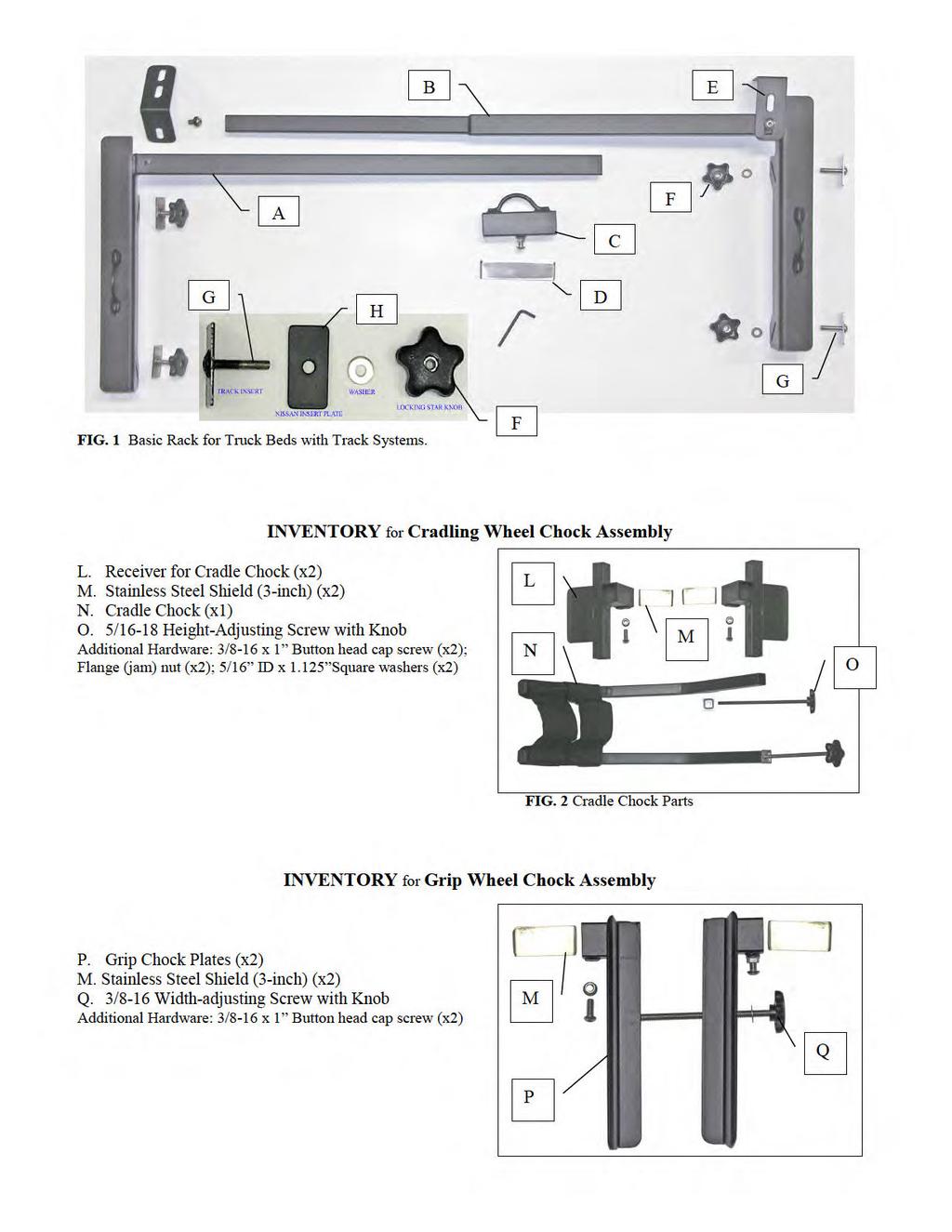
1 8MAY15 US RACK, Inc Falcon Drive, Madera, CA INSTRUCTIONS for Bedrail-mounted MOTORCYCLE RACK, Model TRA WARNING: Do NOT attempt to install or use this rack without following all instructions. SPECIFICATIONS and SAFETY REQUIREMENTS Model TRAN is intended for truck beds 53 to 60 wide having an accessory track system such as the Toyota Deckrail, Nissan Utili-Track, or GM, Ford, or Dodge Track systems. Model TRAW is intended for truck beds 60 to 66 wide having an accessory track system. Each model provides anchor points for tying-down motorcycles and is designed to accommodate up to three dirt or street motorcycles. When used in conjunction with either the Cradle or Grip wheel chocks, the rack helps stabilize the lateral movement of the front wheel of motorcycles with tires up to 5-1/2 inches wide. BE SAFE: Follow all instructions below. Carrying any motorcycle can be hazardous. Make sure all bikes are securely tied down against unexpected winds and vibrations caused by road hazards such as potholes. Check periodically and each time you use the rack to ensure that all fasteners are tight. U.S. Rack cannot be responsible for injury or damage resulting from improper installation or loading of racks. U.S. Rack does NOT warranty any automotive product and does not warranty truck bed rails against damage caused by the weight of excessive loads or forces applied to them when the rack is installed on a vehicle. This rack is intended to carry bikes weighing not more than 600 lbs on paved roadways. It is not intended for use offroad or on poorly maintained roads. The rack must be used with tie-downs to stabilize the motorcycle. The rack is intended to supplement NOT REPLACE the use of tie-down straps. This rack should be checked periodically to ensure that it has not loosened or slid toward the rear of the truck. Carry your bike with the truck tailgate up or with a secure bed extender at the rear to ensure that the bike cannot slide out of the rear of the truck in case of strap or rack failure. Use supplemental tie downs to tie-down the rear of the motorcycle. Read ALL instructions through once BEFORE you do anything! Your safety is paramount. Before assembling the rack, determine which model of rack you purchased including which wheel chocks and inventory and inspect all parts you should have. Visually check each part to ensure it corresponds to the inventory list and check all welds for signs of cracking or weakness. If you do not have all the correct parts, or if any parts appear to be defective, STOP. DO NOT install the rack. Contact customer service at to replace missing or defective parts. If you have any questions about installation, call customer service. Read all instructions and warnings and review all photos prior to beginning assembly. Lay out all parts. NOTE: Some parts and hardware may already be inserted in other parts. INVENTORY Model TRA for Trucks with TRACK SYSTEMS (Refer to Fig. 1) A. Female side of Rack Frame (x1) B. Male side of Rack Frame (x1) C. Moveable Tie-down (x1 minimum) D. Stainless Steel Shield (x1 per Movable Tie-down) E. Headrail Bracket (x2) F. Plastic Knob with nylon locking nut (x4) G. Track Insert (x4) H. Nissan, GM, Ford, or Dodge Insert Plate (x4 if needed) Additional Hardware: 3/8-16 x 1 Button Head Hex Cap Screw (x3); flange (jam) nut (x1); 7/8 OD metal washers (x6); and black nylon washer (x4).
2

. a. Note that there are two kinds or Cradle receivers, which are mirror copies of each other.")
. Note that the wheel chock tubes are connected with black webbing. Orient them so that the webbing is at the bottom.")
3 ASSEMBLY 1. Examine each section of the Rack Frame (items A and B) and notice that each consists of a crossbar with a 20-inch long wing on one end. Place both on a flat surface and orient them so that it is possible to insert the male side of the crossbar into the opening on the female side, but do not yet slide them together. Orient them so that the wings on each side point generally toward you. You should now be looking at the top of the rack. 2. If you purchased Cradle Wheel Chocks, locate and examine the Wheel chock receivers (item L). a. Note that there are two kinds or Cradle receivers, which are mirror copies of each other. Hold a pair of receivers in your hands so that the metal plates are vertical and pointed toward you, and so the small threaded hole, which may contain a screw, is on the outside and pointing down. b. Locate one wheel chock (item N). Note that the wheel chock tubes are connected with black webbing. Orient them so that the webbing is at the bottom. Unscrew the long screw with plastic knob and the square metal washer. Insert the top of each wheel chock tube up into the bottom of the receiver tubes, then re-insert the long bolt with square washers down through the top and screw the bolt back into the threads in the top of each wheel chock tube. Draw the chocks the desired amount into receiver by tightening the screw. c. Place one of the three-inch long stainless steel Shields into each of the short horizontal tubes so they rest on the bottom of the interior of the tube over the hole where the set-screw is located. The edges of each shield should hang down over the edge outside of the tube. The purpose of the shields is to protect the surface of the crossbar from being scratched when the set screw is tightened. Slide the receivers onto the female side of the rack frame. Fig. 5 shows the right side of an unassembled wheel chock and a receiver component and Fig. 6 shows it after it is attached in the receiver. Fig. 7 shows Cradle chocks when mounted on the Crossbar in a pickup. Figs 4. & 5. Wheel chock and receiver during assembly Fig 6. Mounted rack with wheel in webbing of wheel chock 3. If you purchased Grip Wheel chocks, locate and examine the Grip Chock Plates (item P), which are a pair of metal plates welded to short square tubes. a. Note that each set of plates forms a mirrored set. Orient the Grip Plates so they face each other with the square tube on the back, and the set-screws on the outside facing down.

.")

4 b. Locate the three-inch long stainless steel Shields (item M). Place one of these shields into each of the short horizontal tubes so they rest on the bottom of the interior of the tube over the hole where the set-screw is located. The edges of each shield should hang down over the edge outside of the tube. The purpose of the shields is to protect the frame surface from being scratched when the set screw is tightened. Slip a pair of Grip Plates onto the female side of the rack. c. After sliding it on, attach the Grip Plates together using the Width-Adjusting Screw (item Q). Place the metal washer on the end of the screw and insert the end of the screw through the short unthreaded tube on the back of the Plates first and then into the threaded tube. Tightening this screw will draw the plates together as shown in Figs. 8 and 9. Figs 7. Grip Chock before adjustment Fig 8. Grip Chock adjusted to width of wheel 4. Locate and examine the Moveable tie-down (item C) and the 5-inch long stainless steel Shield (item D). The Shield must be inserted into the bottom of the movable tie-down as shown in Fig. 8. Its purposes are to better fix the tie-down in place when the set screw on the bottom side of the tie-down is tightened and to protect the coating on the rack frame from damage. After tightening you will also tighten the flange nut, which acts as a jam nut to prevent the screw from loosening. Slide the Tie-down with Shield onto the female side of the rack. Fig. 9 Moveable Tie-down Fig. 10 Headrail Bracket Fig. 11 Inserting Screw Fig. 12 Tightening 5. Now slide the male end of the rack into the female end. Pick up the assembled rack and hold it so it is parallel to the ground and so the wings (sides) of the rack wrap around you. Make sure the telescoping portion of the rack is compressed all the way together. INSTALLATION 6. Lower the truck tailgate and step up into the truck with the rack. Position yourself just behind the cab, and place the rack down onto the truck so that the wings on each side of the rack rest on the bedrails. It may be necessary to lengthen the telescoping portion of the rack a bit to make it fit your truck bed. Place it so that the telescoping portion is located just behind the front wall of the cargo box. Push the rack forward so that the front of the rack contacts the front wall of cargo box. Now push the rack apart so that the wings of the rack are snug up against the inside edge of your bedrail. Move the Tie-down and any Wheel Chocks to a desired location along the bar. 7. Locate and examine one of the Headrail brackets (item 5) and review Figs 6-8. The purpose of the Headrail bracket is to clamp around the headrail (front bedrail) and prevent the rack from sliding toward the rear.
5 Notice that it has two legs, each with oblong holes. The sides are not of equal length because headrails have different widths. Place the side bracket of the appropriate length on top of the headrail with the other side reaching around the front of the headrail and pointing down. Place the oblong hole over the holes in the top of the rack frame; thread a 1-inch button head cap screw with black nylon washer into the hole. Later, after attaching the rack to the bedrails, you will push the frame firmly against the headrail and tighten the screws firmly to prevent movement. 8. To attach the rack to the track system, follow the steps below. a. First, if your track system has a cap over the end of the track remove the rear cap and side two inserts into the rear end of each track as shown below. Fig. 13 Track with cap Fig. 14 Slide insert into track Fig. 15 Two inserts in track b. Next push one side of the rack away from the bedrail, and slide the inserts forward in the track until they align with the diagonal slots in the side of the rack; then pull the rack back onto the bedrail and onto the ends of the threaded insert. Place a metal washer and plastic knob on the Insert and tighten firmly as shown in the figures below. Fig. 16 Align inserts with slots Fig. 17 Slide slots over inserts add washers Fig. 18 Tighten knobs on inserts LOADING 9. Whenever loading your bike ensure that you use a stable ramp to place it into the bed. NEVER DRIVE YOUR BIKE UP OR DOWN THE RAMP. a. To tie down your bike(s) attach one hook of the strap to the anchor loop on one of the wings and the other to the other wing or to the Movable Tie-down on the crossbar, after it has been firmly tightened. b. If you are using Grip Chocks slide the tire all the way forward between the grip plates and tighten the Widening Screw until the plates make contact with the sides of the tire. Excessive tightening of the screw is not necessary, since the plates are intended only to bracket the tires and limit their lateral movement, with the tie-down straps provide the real power to hold the bike in place. After the width of the Grip Chocks is set, tighten the set screws and jam nuts on the chocks firmly. c. If you are using Cradle Chocks, set the height of the chock so the bottom of the webbing is suspended above the floor of the bed. Slide the tire all the way forward in the chock so the bottom of the tire is resting on the web material. Readjust the Chock height so the bottom of the webbing is suspended about an inch above the floor of the bed with the bike loaded. This ensures that the sides of the Wheel Chock press firmly on the sides of the tire. When the bike is tied down, tighten straps to pull

6 the tire down in firm contact with the floor. After ensuring that the plates of the Receivers are also touching the sides of the tire, tighten the set screws and jam nuts on the Receivers firmly. 10. Warning: Whether you are employing wheel chocks or just using the rack to provide tie-downs, never move your truck without first tying the bike down securely. Check all fasteners before during and after use to ensure that none have vibrated loose. To remove the rack after use, reverse the installation procedures. Fig. 19 Cradle Chocks installed Fig. 12 Grip Chock installed WARRANTY U.S. Rack products are warranted for a period of one year against all structural defects in materials and workmanship provided that they are assembled, installed, and used in accordance with all manufacturer s specifications and instructions. U.S. Rack cannot warrant the powder-coating on its products. Normal use of any powder-coated rack and exposure to weather can result in scratching of the surface, exposing metal below; therefore, maintenance on your rack will be required. To prevent rust, spot paint any scratches or breaks in the surface with a high quality metal paint. Merchandize must be returned in the original box and packaging. See return policies and procedures at
Important Note: Tighten lock nuts so the support tubes still swing freely see figure 2. There must be 1 2 threads of bolt past end of lock nuts.
 Kit Contents: DESCRIPTION QTY. DESCRIPTION QTY. 2 Shank Assembly 1 Support Tube Assembly 1 Side Tube - Short 2 1-1/4 Shank 1 Center Tube - Long 1 3/8-16 x 2.0 Carriage Bolt 2 5/16-18 x 2.25 Carriage Bolt
#59114 Rola 2-Bike Rack Carrier (Shown Assembled) (A) (C) (B)
 (A) (C) (B)") Use for Parts: #59114 Rola -Bike Rack System #59115 Rola 1-Bike Add-On TOOLS REQUIRED 10mm or 13/3 Socket & Wrench #59114 Rola -Bike Rack Carrier (Shown Assembled) Tray Attachment Hardware: (3) Plastic
Use for Parts: #59114 Rola -Bike Rack System #59115 Rola 1-Bike Add-On TOOLS REQUIRED 10mm or 13/3 Socket & Wrench #59114 Rola -Bike Rack Carrier (Shown Assembled) Tray Attachment Hardware: (3) Plastic
VERSA BIKE RACK INSTRUCTIONS
 VERSA BIKE RACK INSTRUCTIONS Models #8, 8 Important This rack is designed for use with a or. receiver hitch. The rack is designed to hold a maximum of two bicycles. Do not use it for anything other than
INSTALLATION INSTRUCTIONS
 KIT CONTENTS: INSTALLATION INSTRUCTIONS PART NUMBER: DESCRIPTION: E361SXA302 roof MOUNT BICycle CARRIER SINGLE Short Carriage Bolt 1x Long Carriage Bolt 3x Over-Molded Wrench 1x Button Head Screw 2x Washer
INSTALLATION INSTRUCTIONS
 INSTALLATION INSTRUCTIONS KIT CONTENTS: PART NUMBER: DESCRIPTION: E361SXA300 ROOF MOUNT BICYCLE CARRIER B9 TRIBECA Short Carriage Bolt Long Carriage Bolt 3x Over-Molded Wrench Button Head Screw 2x Washer
Assembly Instructions. -Cantilever Boat Lifts
 Assembly Instructions -Cantilever Boat Lifts Winch Instruction Page Safety Information 1. The winch is built for the multipurpose of hauling and lifting operations. It is not to be used as a hoist for
Santa Fe Cycles Assembly Guide Introduction
 Santa Fe Cycles Assembly Guide Introduction Congratulations on your purchase of your new Santa Fe bicycle. You have purchased a bicycle that has many features and qualities. Please take a few minutes and
LITERIDER 2&3 IMPORTANT WARNING. 2Bike (1x) Bolt (1x) Nut (1x) Small Hex Wrench (1x)
 Bolt (1x) Nut (1x) Small Hex Wrench (1x)") LITERIDER 2&3 3 Bike (1x) Bolt (1x) Flat Washer (2x) Nut (1x) Large Hex Wrench (1x) 2Bike (1x) wrench (1x) Small Hex Wrench (1x) keys (2x) Long Strap (1x) 2-Zip Strips (6x) 3-Zip Strips (9x) Wheel strap
LITERIDER 2&3 3 Bike (1x) Bolt (1x) Flat Washer (2x) Nut (1x) Large Hex Wrench (1x) 2Bike (1x) wrench (1x) Small Hex Wrench (1x) keys (2x) Long Strap (1x) 2-Zip Strips (6x) 3-Zip Strips (9x) Wheel strap
VERTICAL SURFBOARD CARRIER READ ME! IMPORTANT WARNING!
 VERTICAL SURFBOARD CARRIER ENG RRAC09 30 min READ ME! Thank you for purchasing a Front Runner Vertical Surfboard Carrier. Before you start, take a moment to familiarize yourself with this Fitting Instruction
Marine 6-Boat Free-Standing Racks SKU: Updated November 2011
 Marine 6-Boat Free-Standing Racks SKU: 30-061 Updated November 011 Contains: Marine -Boat Free-Standing Racks (SKU 1-003) Marine 3 rd Boat Expansion Racks (SKU 1-0303) Marine Back Legs (SKU -001) 3 Sets
PRO-III & IV (916) (800) Parts: 80000, 80020, & G Trade Center Drive Rancho Cordova, CA 95742
 (800) Parts: 80000, 80020, & G Trade Center Drive Rancho Cordova, CA 95742") ASSEMBLY ISTRUCTIOS for : PRO-III & IV v _4.1 Parts: 80000, 80020, & 90000 (916) 638-8703 (800) 343-7486 11253- G Trade Center Drive Rancho Cordova, CA 95742 PRO-III & IV ALL MODELS FOR TRUCKS WITHOUT
ASSEMBLY ISTRUCTIOS for : PRO-III & IV v _4.1 Parts: 80000, 80020, & 90000 (916) 638-8703 (800) 343-7486 11253- G Trade Center Drive Rancho Cordova, CA 95742 PRO-III & IV ALL MODELS FOR TRUCKS WITHOUT
HoldUp Plus2. Safety Kit included: See additional instructions for installation. REAR WHEEL TRAY. BASE (1x) lock WASHER (1x) KEY (2x) SAFETY CLIP (1x)
 lock WASHER (1x) KEY (2x) SAFETY CLIP (1x)") HoldUp Plus2 InsTAll This product on 2" hitch version of the HoldUp Front WHEEL TRAY assembly (1x) REAR WHEEL TRAY assembly (1x) wrench (1x) BASE (1x) bolt (8X) Lock WASHER (8X) Washer (8x) KEY (2x) SAFETY
HoldUp Plus2 InsTAll This product on 2" hitch version of the HoldUp Front WHEEL TRAY assembly (1x) REAR WHEEL TRAY assembly (1x) wrench (1x) BASE (1x) bolt (8X) Lock WASHER (8X) Washer (8x) KEY (2x) SAFETY
QUALITY ALUMINUM BOAT LIFTS, INC. INSTRUCTIONS. Dominator Lake Lift
 INSTRUCTIONS Dominator Lake Lift PHONE:251-986-3882 * FAX:251-986-3136 QABLDOMINATORINST.2014 P a g e 1 Quality Aluminum Boat Lifts, INC. Installation Instructions: Dominator Lake Lift Thank you for your
OWNERS MANUAL. Model Shown with optional Primary Mooring Cleats. Portable Mooring System SAFETY OPERATION MAINTENANCE PARTS
 OWNERS MANUAL Model 2400 Shown with optional Primary Mooring Cleats. Portable Mooring System SAFETY OPERATION MAINTENANCE PARTS CAUTION: Before using your new Pier Tender, read rules for Safety, Operation,
Bike Rack and Spare Tire Carrier 1-1/4" Receiver
 Bike Rack and Spare Tire Carrier 1-1/4" Receiver OWNER'S MANUAL Rev: 11.15.2017 Page 1 Bike Tire Carrier 1.25 Owners Manual TABLE OF CONTENTS Safety Information 2 Product Information 2 Installation 3 Installation
E-trike Li Assembly Guide
 PREPARATION 1. Read this assembly manual BEFORE commencing assembly. 2. Carefully remove all the components and packaged hardware from the shipping boxes. 3. Unpack the contents of the large double box
Installation Instructions
 116-3027, 116-3017 X-Pando Adjustable Steel Protector Installation Instructions 1404 N. Marshall Ave. El Cajon CA. 92020 For technical support call us at (800) 368-3075 NB 6/28/10 607-0112 Step 1. Mounting
Bike Rack and Tire Carrier
 Bike Rack and Tire Carrier OWNER'S MANUAL Rev: 10.26.2017 Page 1 Bike Rack and Tire Carrier Owners Manual TABLE OF CONTENTS System 2 Description 2 Prior To Operation 3 Manual Slide-Out Bike Rack Operation
Ladies Shopper Bike Assembly Manual 28C03
 Ladies Shopper Bike Assembly Manual 28C03 Ecosmo Ltd 1 Know your bike 1. Wheel 2. Rear Derailleur 3. Chain 4. Crank Set 5. Pedal 6. Seat Quick Lock 7. Saddle and Post 8. Frame 9. Front Light 10. Front
PART NUMBER: E361SXA200 DESCRIPTION: KAYAK CARRIER
 A KIT CONTENTS: : Plug 16x Long Carriage Bolt 4x Hex Key 4x Button Head Screw 4x Pad Strap BASE Over-Molded Wrench 1x SnapAround 4x 1/5 : Important Notes: Minimum crossbar spread of 24". If spread is less
Final Assembly Instructions Bikes with Quill Stems
 Final Assembly Instructions Bikes with Quill Stems Thank you for buying your new bicycle from L.L.Bean. Read these instructions carefully before beginning the final assembly. Prior to shipping, our expert
Page 1. Single Scull Car Rack Assembly and User s Manual " "
 Page 1 Single Scull Car Rack Assembly and User s Manual Page 2 Items in the box: (2) V cradles (2) 4 rails (1) 1 3/4 X 18 rail coupler (4) 1/4-20 X 4 1/2 bolts (2) 1/4-20 X 2 1/2 bolts (12) 1/4 flat washers
RADROVER REAR RACK INSTALLATION MANUAL
 RADROVER REAR RACK INSTALLATION MANUAL WWW.RADPOWERBIKES.COM We are here to help! Please contact us at SUPPORT@RADPOWERBIKES.COM or 1-800-939-0310 if you have questions. REV022216 Welcome Thanks you for
600 / 600FC OWNER'S MANUAL
 PROGRESSION 600 / 600FC OWNER'S MANUAL Issue 2 / Version E - Dec. 10, 1997 Copyright 1997 GAMMA Sports - All Rights Reserved PROGRESSION 600 / 600FC OWNER'S MANUAL TABLE OF CONTENTS PAGE 1... WARRANTY
Thank you for purchasing a Porta-Dock product! *Please read and follow these instructions step by step*
 PG 1 OF 9 PORTA-DOCK, INC. 74A ABL/APW 1056 & 44A FLB APW 1056 PORTA-LIFT Thank you for purchasing a Porta-Dock product! *Please read and follow these instructions step by step* STEP 1. Separate and group
Side-of-Pole Mount for 1 Module (SPM1) For Module Types A & B
 For Module Types A & B") Side-of-Pole Mount for 1 Module (SPM1) For Module Types A & B ASSEMBLY INSTRUCTIONS step-by-step assembly and installation Version 1, Rev A PCN 080311-2 SP3363-1 Side-of-Pole Mount for 1 Module (SPM1)
Side-of-Pole Mount for 1 Module (SPM1) For Module Types A & B ASSEMBLY INSTRUCTIONS step-by-step assembly and installation Version 1, Rev A PCN 080311-2 SP3363-1 Side-of-Pole Mount for 1 Module (SPM1)
Caliber Sled Wheels Assembly Instructions for PN and 13579
 Caliber Sled Wheels Assembly Instructions for PN 13576 and 13579 Caution: Read all instructions before assembling or using Sled Wheels. Follow the steps in order. Only use Sled Wheels as intended, following
PRO-II. ASSEMBLY INSTRUCTIONS for : (916) (800) Parts: and 01040
 (800) Parts: and 01040") ASSEMBLY INSTRCTIONS for : PRO-II Parts: 000 and 040 12_1.1 www.kargomaster.com (916) 638-8703 (800) 343-7486 11261 Trade Center Drive Rancho Cordova, CA 95742 1 PASSENGER SIDE CANNEL 2 J All models for
ASSEMBLY INSTRCTIONS for : PRO-II Parts: 000 and 040 12_1.1 www.kargomaster.com (916) 638-8703 (800) 343-7486 11261 Trade Center Drive Rancho Cordova, CA 95742 1 PASSENGER SIDE CANNEL 2 J All models for
C - SERIES. Height Adjustable Portable Goal Supports. Installation & Owner s Instructions C1000 C2000. Made in the USA
 C - SERIES Height Adjustable Portable Goal Supports C1000 C2000 Installation & Owner s Instructions Made in the USA This manual explains the proper installation, operation, and maintenance of your Schutt
NEXT EXIT THE GREAT OUTDOORS POPULATION: EVERYONE
 2017 NEXT EXIT THE GREAT OUTDOORS POPULATION: EVERYONE SportRack is proud to offer safe, quality products that allow you to take full advantage of your vehicle s carrying capacity. SportRack accessories
Stand-N-Fish FULL DETAIL INSTALLATION INSTRUCTIONS
 1 Stand-N-Fish FULL DETAIL INSTALLATION INSTRUCTIONS Thank you for purchasing the incredible new Stand-N-Fish Kayak Fishing System. Once installed on your kayak the Stand-N-Fish will take your kayak fishing
IMPORTANT WARNING SOUL PAD (2X) PAD STRAP (4X) S.U.P. BRAH (1X) KEYS (2X) RIPCORD (2X) HOOK (2X) NOSE/TAIL STRAP (2X)
 PAD STRAP (4X) S.U.P. BRAH (1X) KEYS (2X) RIPCORD (2X) HOOK (2X) NOSE/TAIL STRAP (2X)") SOUL PAD (2X) PAD STRAP (4X) S.U.P. BRAH (1X) KEYS (2X) HOOK (2X) RIPCORD (2X) NOSE/TAIL STRAP (2X) IMPORTANT WARNING IT IS CRITICAL THAT ALL YAKIMA RACKS AND ACCESSORIES BE PROPERLY AND SECURELY ATTACHED
SOUL PAD (2X) PAD STRAP (4X) S.U.P. BRAH (1X) KEYS (2X) HOOK (2X) RIPCORD (2X) NOSE/TAIL STRAP (2X) IMPORTANT WARNING IT IS CRITICAL THAT ALL YAKIMA RACKS AND ACCESSORIES BE PROPERLY AND SECURELY ATTACHED
CHAINLESS ANCHORING SYSTEM USER MANUAL
 CHAINLESS ANCHORING SYSTEM USER MANUAL Introduction..................................................... 1 Setting up the Chainless Anchoring System............................ 4 Set up Procedure............................................
SERIES 2 RAMP OWNER S MANUAL TOOLS REQUIRED: BEFORE YOU BEGIN... Read and understand these instructions before beginning a ramp setup.
 SERIES 2 RAMP OWNER S MANUAL BEFORE YOU BEGIN... Read and understand these instructions before beginning a ramp setup. Use caution and care for your back when lifting, pushing, pulling, folding or unfolding
INSTALLATION INSTRUCTIONS
 INSTALLATION INSTRUCTIONS Accessory (ROOF) P/N 08L07-E09-100 Application 6 PILOT Publications No. Issue Date JUN 5 PARTS LIST 6 Washers Bicycle attachment 2 Brackets Hex wrench 4 Knobs 2 Keys 1 Rear Bracket
SASK-A-POLE OWNERS AND USERS MANUAL
 SASK-A-POLE OWNERS AND USERS MANUAL GENERAL INFORMATION The Saskatchewan Abilities Council s Sask-a-Pole accessibility and transfer aid is designed to help provide safe and easy access to chairs, beds,
Troyer s Gourd Rack 8 unit F R H O P
 B E A D I M-N L Vertical Parts F R H O P Horizontal Parts C G J Updated 11/16 Parts List A: Top of Pole B: Bottom of Pole C: 48 Ground Stake D: Top Perch rods 48 long E: Hub F: Rope Winder w/ attached
Lock-N-Load. Bullet Feeder
 Lock-N-Load Bullet Feeder table of contents steps Overview... 2 List of required hand tools... 2 1: Mounting the Bullet Feeder to the Bench... 3 2: Mounting the Bullet Feed Hopper... 4 3: Bullet Feed Hopper
Thank you for purchasing a WIKE BOX BIKE!
 Thank you for purchasing a WIKE BOX BIKE! Contents Safety.....3 Front wheel.4 Kickstand..5 Handle Bar & Box 6 Seat post and Saddle 7 Final pre-ride check 8 Tools needed to assemble Bike: -High table or
Final Assembly Instructions Bikes with Threaded Headsets
 Final Assembly Instructions Bikes with Threaded Headsets Thank you for buying your new bicycle from L.L.Bean. Read these instructions carefully before beginning the final assembly. Prior to shipping, our
U.S. Patent No. 7,922,246. Patents Pending
 U.S. Patent No. 7,922,246 Patents Pending 2 Table of Contents Page General Information... 3 Warnings and Cautions... 4 Tools... 6 SmartDock Parts... 6 Initial Set-Up and Adjustment... 7 Select Valve Retaining
Installation Guide RHT-380. This Manual Must Be Read Before Operating The Equipment CUSTOMER COPY
 Installation Guide This Manual Must Be Read Before Operating The Equipment RHT-380 Madison Heights, Michigan 48071 800-725-8377 www.snowexproducts.com CUSTOMER COPY Trynex International 2013 (REV B) F50767
GRAVITY BIKE RACK ASSEMBLY & OPERATING INSTRUCTIONS
 GRAVITY BIKE RACK 94479 ASSEMBLY & OPERATING INSTRUCTIONS Due to continuing improvement, actual product may differ slightly from the product described herein. 3491 Mission Oaks Blvd., Camarillo, CA 93011
ALTERNATOR RACKS 135, 170 & 190 INSTRUCTIONS
 Figure A Item # Description Quantity 1 Alternator Rack 1 1 3 4 11 5 10 8 2 Lower Mount Kit (see detail) 2 3 16mm M5 Swivel-Mount Bolt 2 4 M7 Washer 2 5 M6 Lock Nut 2 6 Lock Washer 2 7 Swivel Mount 2 8
602 STRINGING MACHINE OWNER'S MANUAL
 PROGRESSION 602 STRINGING MACHINE OWNER'S MANUAL AL Issue 1- April 2000 Copyright 2000 GAMMA Sports - All Rights Reserved PROGRESSION 602 STRINGING MACHINE TABLE OF CONTENTS PAGE 1... WARRANTY PAGE 2...
STAND AID 1600/ ECONOSTAND
 MAKERS OF STAND AID, POWER TOILET AID AND FREEDOM CHAIR STAND AID 600/ ECONOSTAND INSTRUCTIONS AND WARRANTY FOR STAND AID 600 STAND AID SERIAL # PO BOX 386 Sheldon, IA 50 (800) 83-8580 (7) 34-53 Fax: (7)
Design Based Anchoring 2009 FORD F-150
 Design Based Anchoring OWNERS MANUAL USERS MANUAL 2008 Chief Automotive Technologies. CHIEF'S LIMITED ONE-YEAR WARRANTY & LIABILITY Chief Automotive Technologies warrants for one year from date of installation
RS Important Notes. Contact. Bicycle Maintenance Stand instructions manual. Warranty Period : 1 year (from the date of your purchase)
") Warranty Period : 1 year (from the date of your purchase) RS-1700 Bicycle Maintenance Stand instructions manual (ver.1.2 2016/12) For more details, read the attached "Minoura Limited Warranty Policy" card.
Warranty Period : 1 year (from the date of your purchase) RS-1700 Bicycle Maintenance Stand instructions manual (ver.1.2 2016/12) For more details, read the attached "Minoura Limited Warranty Policy" card.
Instructions. Follow All Instructions Before Assembling Or Using This Product
 Instructions Follow All Instructions Before Assembling Or Using This Product IMPORTANT DO NOT RETURN THIS PRODUCT TO THE RETAIL STORE WHERE PURCHASED. CALL TOLL FREE: (800) 492-9334 WARNING: Improper use
-- SGP (NOVA TEAM SQUARE)
") -- SGP-100 -- (NOVA TEAM SQUARE) Installation Instructions Call Jaypro Sports Equipment at 1-800-243-0533 during regular business hours for technical support. www.jaypro.com Rev-B Page 1 of 9 JAYPRO SPORTS
-- SGP-100 -- (NOVA TEAM SQUARE) Installation Instructions Call Jaypro Sports Equipment at 1-800-243-0533 during regular business hours for technical support. www.jaypro.com Rev-B Page 1 of 9 JAYPRO SPORTS
SPINNER RIDE GETTING STARTED GUIDE. Welcome to a personalized fitness experience for your members
 This addendum accompanies your equipment documentation and is additional information concerning the heart rate features for your equipment and console. Important The heart rate feature is intended for
INSTALLATION INSTRUCTIONS
 INSTALLATION INSTRUCTIONS Accessory (ROOF) P/N 08L07-E09-100 Application 2013 CROSSTOUR Publications No. AII 13168 Issue Date NOV 2012 PARTS LIST 6 Washers Bicycle attachment 2 Brackets Hex wrench 4 Thumbwheel
walk with independence
 walk with independence Lightweight www.novamedicalproducts.com WARNING Failure to follow any or all safety instructions may result in serious injury or death. adjustment and usage yourself or ambulate
Installation Instructions for the AlphaDeck Staging System
 Installation Instructions for the AlphaDeck Staging System Step 1 - Preparation A. Before setting up this system, determine the location of the stages and all the parts you will need. B. Read through the
STRONGMAN. High Security U-Lock 100% HARD. ENGLISH 2-x DEUTSCH x-x ESPANOL x-x ITALIANO x-x JAPANESE x-x FRENCH x-x. LOCKS BY KNOG
 STRONGMAN High Security U-Lock 100% HARD LOCKS BY KNOG www.knog.com.au ENGLISH 2-x DEUTSCH x-x ESPANOL x-x ITALIANO x-x JAPANESE x-x FRENCH x-x ENGLISH CONTENTS Strongman components 4 How to lock your
BICYCLE TO MOTORCYCLE BICYCLE RACK
 BICYCLE TO MOTORCYCLE BICYCLE RACK Install Manual Warning: You are responsible for securing the rack to your motorcycle., checking the attachments prior to use and periodically inspecting the products
X-6 STRINGING MACHINE OWNER'S MANUAL. Issue 1 - May Copyright 2004 GAMMA Sports - All Rights Reserved
 X-6 STRINGING MACHINE OWNER'S MANUAL Issue 1 - May 2004 Copyright 2004 GAMMA Sports - All Rights Reserved OWNER'S MANUAL GAMMA X-6 TABLE OF CONTENTS PAGE 1... WARRANTY PAGE 2... FEATURES PAGE 3...ASSEMBLY
INSTRUCTIONS 360 Y-DROP HAGIE STS 2015
 INSTRUCTIONS 60 Y-DROP HAGIE STS 05 INSTRUCTIONS 60 Y-DROP HAGIE STS 05 INTRODUCTION Before beginning, it s important to know where each mounting bracket fits relative to the row spacing involved. The
TWO KAYAK VERTICAL FOLD-DOWN CARRIER
 S P X O TWO KAYAK VERTICAL FOLD-DOWN CARRIER TA R 2 50mm 40mm Stax Pro2 Kayak Carrier Red Load Straps Jawz Adapters Mounting Bolts Foam Blocks 9 Safety Strap 12 Tie-Downs Installation & Loading Instructions
TWO BIKE UPRIGHT ROOF MOUNT BIKE CARRIER
 TWO IKE UPRIGT ROOF OUNT IKE CRRIER NOTE: Please read instructions carefully before installation. Please refer to assembly instructions, and ensure the bike carrier is installed correctly. Please keep
Final Assembly Instructions Bikes with 16 Wheel Size
 Final Assembly Instructions Bikes with 16 Wheel Size Thank you for buying your new bicycle from L.L.Bean. Read these instructions carefully before beginning the final assembly. Prior to shipping, our expert
FIRST TEAM SPORTS, INC Storm Portable Series Assembly Instructions
 FIRST TEAM SPORTS, INC Storm Portable Series Assembly Instructions WARNING! WARNING! WARNING! THIS BASKETBALL SYSTEM IS SPRING LOADED AND SHIPPED UNDER TENSION. ATTEMPTING TO ASSEMBLE OR DISASSEMBLE ANY
BackCountry ebikes 2019 MULE Assembly
 BackCountry ebikes 2019 MULE Assembly Required Tools: Cutting Pliers (to cut box poly strapping and heavy bike banding) Scissors (to remove bubble wrap) Allen wrenches (3mm, 4mm, 5mm, 6mm) Wrenches (10mm,
A. TO PREPARE THE MACHINE FOR USE.
 INSTRUCTION MANUAL FOR THE ML120 STRINGING MACHINE. CONTENTS: A. TO PREPARE THE MACHINE FOR USE. 1. The assembly of frame with console and tooltray. 2. Fixing the lever of the tension unit. 3. Putting
Installation Operating Instructions for Simple Duplex Manual Manifolds PX-TSD Series
 Introduction Powerex manifolds are cleaned, tested and prepared for the indicated gas service and are built in accordance with the Compressed Gas Association guidelines. The manifold consists of a regulator
To address this issue, Ariens Company has developed two cradle plates kits:
 Date: August 21, 2012 No. B-2093 Service Bulletin Ariens Company 655 W. Ryan St. Brillion, WI 54110 www.gravely.com Product Family: Pro-Turn 400 Mowers Subject: Possible Foot Plate Weld Fracture Dealer
3. Align ratchet drive with female insert on assembly, and raise ratchet handle until the ratchet drive is firmly seated into the assembly.
 Remote Bung Cap Removal Tool Assembly Instructions 1. Pull collar down on ratchet to fully extend. 2. Insert ratchet head and neck under spring. 3. Align ratchet drive with female insert on assembly, and
Parts: Included in the parts box: Inner Rear Tire Tray. Inner Front Tire Tray. Trail Doc Clamp. Pivot Assembly. Trail Doc Post.
 NV 2.0 2 Parts: Outer Front Tire Tray Inner Front Tire Tray Outer Rear Tire Tray Inner Rear Tire Tray Pivot Assembly Trail Doc Clamp Trail Doc Post Included in the parts box: 6mm Allen Wrench M6 Lock Washer
Rhino-Rack Mountain Trail Bike Carrier (RBC035)
") Important: Please read these instructions carefully prior to installation. Please refer to your fitting instruction to ensure that the bike rack is installed in the correct locations. Check the contents
Important: Please read these instructions carefully prior to installation. Please refer to your fitting instruction to ensure that the bike rack is installed in the correct locations. Check the contents
comfort without compromising on performance and to fit your various needs on touring,
 Congratulations on your purchase of Goal-26X. Goal-26X is made to enhance comfort without compromising on performance and to fit your various needs on touring, shopping and communicating. Let s have fun
Mounting Instructions 2010 Wolfman Expedition Dry Saddlebags or Teton Saddlebags to another brand of Rectangular Side Rack.
 Mounting Instructions OTHER 2010 Wolfman Expedition Dry Saddlebags or Teton Saddlebags to another brand of Rectangular Side Rack. Thank You for purchasing our new 2010 Wolfman Products Please Note: The
TRAILMATE METEOR ASSEMBLY MANUAL
 TRAILMATE METEOR ASSEMBLY MANUAL (DISC BRAKE VERSION) The Trailmate Meteor recumbent has been designed for easy assembly. This means more time to enjoy the smooth ride with single speed, 3 speed coaster
IMPORTANT: RECEIVING INSTRUCTIONS:
 Instruction Sheet Sidewinder Mechanical Bender IMPORTANT: RECEIVING INSTRUCTIONS: Visually inspect all components for shipping damage. If any shipping damage is found, notify carrier at once.shipping damage
Soccer Goal. Model: SG20 Series. Installation, Operation and Maintenance Instructions
 Soccer Goal Model: SG20 Series Installation, Operation and Maintenance Instructions Please read all instructions before attempting installation or operation of these units SAVE THESE INSTRUCTIONS FOR FUTURE
2012 K9100 COMPACT Worldwide Cycling Solutions Through Creative Innovations.
 Home Instruction Sheet Step-1Please check for any missing parts. Model K9100 COMPACT (Basic AirCaddy) aircaddy web page 20 04/03/12 98% (1) T3230-00 METAL WHEEL TRUCK Model K8350 (Aircraft Kit) (Optional)
Trilogy Theory of Operation
 INSTALLATION & OVERVIEW... 2 Load Height... 2 Approach Angle... 2 Footprint... 3 Protrusion... 3 Mounting the... 4 General Torque Specs... 4 OPERATION OF BIKE RACK... 5 Loading Bikes... 5 Unloading Bikes...
IMPORTANT SAFETY NOTICE
 OWNER S MANUAL NOTE: Any photos of the YBIKE or decals in the owner s manual are intended to be used as a reference only, and there may be some differences to the unit you purchased. IMPORTANT SAFETY NOTICE
To Purchase This Item, Visit BMI Gaming (800)
") How to play the game How to play the game The object of the game is to reach the Game Goal before your opponent. HOW TO START: - A coin toss decides who starts the game. The winner of the coin toss also
How to play the game How to play the game The object of the game is to reach the Game Goal before your opponent. HOW TO START: - A coin toss decides who starts the game. The winner of the coin toss also
Universal Elevator Mount Owners Manual Customer Service Center N53 W24700 South Corporate Circle Sussex, WI U.S.A.
 REQUIRED TOOLS AND MATERIALS: 2 Capable Adults Carpenter s Level 15 Tape Measure Pencil Universal Elevator Mount Owners Manual Customer Service Center N53 W2400 South Corporate Circle Sussex, WI 530 U.S.A.
Important Information
 Kayak Stack (S50) Important: Please read these instructions carefully prior to installation. Please refer to your fi tting instruction to ensure that the bike rack is installed in the correct locations.
Chapter 2 Rigging. Cutting Wire Rope. Anchoring Wire Rope to Drum. Winding Wire Rope Onto Drum
 Chapter 2 Rigging Cutting Wire Rope The wire rope must be tightly seized on both sides of the point where the wire rope will be cut, as shown in Figure 2-1. Seize the wire rope with either seizing wire
Magnetic Bike. Model No: AENERGISER BODY WORX. Retain this owner s manual for future reference Read and follow all instructions in this owner s manual
 BODY WORX Magnetic Bike Model No: AENERGISER Retain this owner s manual for future reference Read and follow all instructions in this owner s manual Version A 1 EXPLODE DRAWING -02- PARTS LIST AND TOOLS
OWNER'S MANUAL. Copyright 2003 GAMMA - All Rights Reserved
 OWNER'S MANUAL AL Issue 1 - December 2003 Copyright 2003 GAMMA - All Rights Reserved OWNER'S MANUAL TABLE OF CONTENTS PAGE 1... WARRANTY PAGE 2... ASSEMBLY INSTRUCTIONS PAGE 4... MOUNTING THE RACQUET PAGE
ASSEMBLY INSTRUCTIONS
 XR 9-2009:new odc 1018 revised 2/17/10 9:11 AM Page 1 ODC XR 9 OUTDOOR DISCOVERY CRAFT ASSEMBLY INSTRUCTIONS Your ODC XR 9 Pontoon Boat comes in two separate cartons consisting of the following parts:
1500 Follow Spot Yoke
 1500 Follow Spot Yoke Rev 1.1 2004 City Theatrical, Inc. Getting Started with the City Theatrical Follow Spot Yoke Congratulations on the purchase of your City Theatrical Follow Spot Yoke. The City Theatrical
Falcon 3 145, 170, 195 and Tandem Owner / Service Manual
 Falcon 3 145, 170, 195 and Tandem Owner / Service Manual January 2007 - Second Edition Removing The Sail From The Airframe And Short Packing The Glider Many maintenance and repair procedures will require
ORNAMENTAL CANTILEVER GATE INSTRUCTIONS
 U.S.A. Patent Number 5,36,83 ORNAMENTAL CANTILEVER GATE INSTRUCTIONS *NOTICE: Ornamental Cantilever Gates are supplied with rolls of 2 mesh safety screening in sufficient quantities to cover the entire
Shoreline Cantilever Lift 2500lb Capacity Models: (108" inside width) - Part # (120" inside width) - Part #
 - Part # (120 inside width) - Part #") Shoreline Cantilever Lift 2500lb Capacity Models: 25108 (108" inside width) - Part # 1017402 25120 (120" inside width) - Part # 1017403 1. 2. 3. 4. 5. CAUTION - PUT SAFETY FIRST Before attempting to install
Shoreline Cantilever Lift 2500lb Capacity Models: 25108 (108" inside width) - Part # 1017402 25120 (120" inside width) - Part # 1017403 1. 2. 3. 4. 5. CAUTION - PUT SAFETY FIRST Before attempting to install
Side-of-Pole Mount for 1 Module (SPM1) For Module Type C
 For Module Type C") Module Type Width Length C 22-27 56-63 Side-of-Pole Mount for 1 Module (SPM1) For Module Type C ASSEMBLY INSTRUCTIONS step-by-step assembly and installation Version 1, Rev A PCN 022212-1 Side-of-Pole Mount
Module Type Width Length C 22-27 56-63 Side-of-Pole Mount for 1 Module (SPM1) For Module Type C ASSEMBLY INSTRUCTIONS step-by-step assembly and installation Version 1, Rev A PCN 022212-1 Side-of-Pole Mount
OWNER'S MANUAL. Copyright 1999 ATS - All Rights Reserved
 OWNER'S MANUAL AL Issue 2 - August 19, 1999 Copyright 1999 ATS - All Rights Reserved OWNER'S MANUAL TABLE OF CONTENTS PAGE 1... WARRANTY PAGE 2... ASSEMBLY INSTRUCTIONS PAGE 4... MOUNTING THE RACQUET PAGE
Rudder Kit Assembly Instructions for Quest 13
 Rudder Kit Assembly Instructions for Quest 13 Revised 4/2/2015 78501 Rudder System The Hobie Quest is designed for the addition of an optional rudder system. Rudder systems in boats like this allow you
READ ALL INSTRUCTIONS AND WARNINGS BEFORE USING THIS PRODUCT.
 Drywall Stills DS1830 Max Weight Capacity 225 Lb READ ALL INSTRUCTIONS AND WARNINGS BEFORE USING THIS PRODUCT. This manual provides important information on proper operation & maintenance. Every effort
VISIT THE LIFETIME WEB SITE: **For U.S. and Canada Customers ONLY:** IF ASSISTANCE IS NEEDED,
 MODEL #73729 WARNING Failure to comply with any of the warnings in these instructions may result in serious personal injuries such as cuts, broken bones, nerve damage, paralysis, brain injury, or death.
SKYBIRD TRAP OWNER S / OPERATOR S MANUAL PARTS AND ASSEMBLY INSTRUCTIONS
 SKYBIRD TRAP PART NO. 40903 OWNER S / OPERATOR S MANUAL PARTS AND ASSEMBLY INSTRUCTIONS WARNING: THIS MACHINE CAN CAUSE SERIOUS INJURY OR DEATH! THOROUGHLY READ INSTRUCTIONS AND SAFETY INFORMATION BEFORE
Tripod Setup Guide (M-TPx)
") Items needed: 1/2 inch wrench, mast level (M-MLA), medium size wire cutters, crescent wrench, all-purpose grease, tape measure, tie wraps, redi-mix cement (optional), shovel (optional), sledge hammer (for
Items needed: 1/2 inch wrench, mast level (M-MLA), medium size wire cutters, crescent wrench, all-purpose grease, tape measure, tie wraps, redi-mix cement (optional), shovel (optional), sledge hammer (for
INSTALLATION INSTRUCTIONS. Parts List. Tools Required. Before You Begin. Installation. Customer Information BICYCLE ATTACHMENT JUL.
 INSTALLATION INSTRUCTIONS JUL. 2006 Parts List Bicycle attachment Key plates (2) Tools Required Phillips screwdriver Flat-tip screwdriver Before You Begin Customer Information This Bicycle Attachment is
INSTRUCTION MANUAL. January 23, 2003, Revision 0
 INSTRUCTION MANUAL Model 810A In-Vitro Test Apparatus for 310B Muscle Lever January 23, 2003, Revision 0 Copyright 2003 Aurora Scientific Inc. Aurora Scientific Inc. 360 Industrial Parkway S., Unit 4 Aurora,
SAVE THESE INSTRUCTIONS. NOTE: Check all parts for shipping damage. In case of damage, DO NOT use. Contact Carrier/Invacare for further instructions.
 Walking Tutor, Installation and Operating Instructions Model No. WT 200 SAVE THESE INSTRUCTIONS NOTE: Check all parts for shipping damage. In case of damage, DO NOT use. Contact Carrier/Invacare for further
Assembly Guide ST200 FUNCTIONAL TRAINER
 Assembly Guide ST200 FUNCTIONAL TRAINER Assembly Guide ST200 FUNCTIONAL TRAINER To avoid possible damage to this Functional Trainer, please follow these assembly steps in the correct order. Before proceeding,
Football Equipment. 5 9/16" Gooseneck Goalposts
 5 9/16" Gooseneck Goalposts Football Equipment FB55CG 5 9/16" Gooseneck College Goalposts Applies also to FB55CG-SY and FB55CG-WT Goalposts shall meet all NCAA rules. Goalposts shall be of the single bent