LIQUIP DRYBREAK COUPLER. API800 Series MAINTENANCE INSTRUCTIONS
|
|
|
- Christian Toby Norris
- 6 years ago
- Views:
Transcription

1 LIQUIP DRYBREAK COUPLER API800 Series MAINTENANCE INSTRUCTIONS API LOADING COUPLER TO API RP1004 June 2015 Issue: F M:\Product-Info\API8xx\6-Service-Maintenance\API800 MAINTENANCE INSTRUCTIONS doc Issue: F 30/06/15 Page 1
2 CONTENTS API800 Series Datasheet... 3 API800 Series Drawing... 4 API800 Series Parts List... 5 API800 Series Exploded View... 6 What You Will Need... 6 Testing For Excessive Wear... 8 Suggested Maintenance Schedule... 8 Replace Product Seal (In-Situ)... 9 Replace Outer O-Ring (In-Situ) Replace Bush And O-Ring Assembly (In-Situ) Disassemble And Reassemble Procedure disaaemble (On Work Bench) Disassemble And Reassemble Procedure - reassemble (Continued) Optional Method To Replace Coupler Internals (On Work Bench) Troubleshooting Spare Parts M:\Product-Info\API8xx\6-Service-Maintenance\API800 MAINTENANCE INSTRUCTIONS doc Issue: F 30/06/15 Page 2

3 API800 Series Datasheet M:\Product-Info\API8xx\6-Service-Maintenance\API800 MAINTENANCE INSTRUCTIONS doc Issue: F 30/06/15 Page 3

4 API800 SERIES DRAWING M:\Product-Info\API8xx\6-Service-Maintenance\API800 MAINTENANCE INSTRUCTIONS doc Issue: F 30/06/15 Page 4
5 API800 SERIES PARTS LIST NOTE: For a list of available spare parts please refer to section 9. M:\Product-Info\API8xx\6-Service-Maintenance\API800 MAINTENANCE INSTRUCTIONS doc Issue: F 30/06/15 Page 5

6 API800 SERIES EXPLODED VIEW M:\Product-Info\API8xx\6-Service-Maintenance\API800 MAINTENANCE INSTRUCTIONS doc Issue: F 30/06/15 Page 6


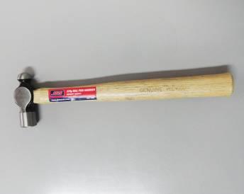
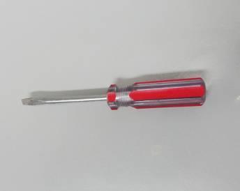
7 WHAT YOU WILL NEED Roll Pin Punch for 5mm pin 4mm Allen Key Internal Circlip M32 Pliers (For bush and o-ring assembly circlip) Hammer Flathead Screwdriver or O-Ring Pick M:\Product-Info\API8xx\6-Service-Maintenance\API800 MAINTENANCE INSTRUCTIONS doc Issue: F 30/06/15 Page 7
8 ATTENTION THE STEPS OUTLINED IN THIS DOCUMENT MUST BE PERFORMED BY AUTHORISED PERSONNEL ONLY. FOR FURTHER EXPLANATION PLEASE CONTACT YOUR LIQUIP REPRESENTATIVE. 1. TESTING FOR EXCESSIVE WEAR Option 1: Connect an API-LI to the API 800 series coupler. Please consult Liquip for more info on the API-LI. Option 2: Connect the coupler to a new API vehicle adaptor. With the vehicle adaptor clamped securely in a vice try to rock the coupling in relation to the vehicle adaptor. Be sure to rock the coupler about the axis which it would normally receive the most wear and tear. If there is any more than 5mm lateral movement at the back end of the coupler it is worn out and unserviceable. 2. SUGGESTED MAINTENANCE SCHEDULE Recommended Service Schedule for Liquip International API800 Series Couplers. Because loading gantries vary in usage the following schedule is calculated on the number of connections. 1. DETERMINE THE LOADING GANTRY CATEGORY Note: All Chemical Couplers should be treated and maintained as per the HIGH USE schedule. a. LOW USE: 1 to 10 Connections per day. b. MEDIUM USE: 11 to 20 Connections per day. c. HIGH USE: 21 to 50 Connections per day. Choose a category that best suits your loading gantry. 2. SERVICE NUMBER a. SN 1 i. Visually inspect the product seal for damage, replace if required. ii. Visually inspect latches for dirt build up and clean if required. iii. Inspect handle interlock for damage, report and locate cause if evident. iv. Visually inspect for leaks on all sealing areas while the coupler is on the loading arm. b. SN 2 As SN1 with the addition of: i. Check the operation of the self-latching mechanism for smooth and free operation. ii. Visually inspect the latches for excessive wear. iii. Visually inspect poppet adaptor ring for damage. iv. Visually inspect the body adjacent to the poppet adaptor ring for mushrooming and/or burrs. v. Visually inspect the poppet face for damage. c. SN 3 As SN1 and SN2 with the addition of: i. Strip and remove shaft and bush assembly and replace o-ring and bush assembly. ii. Check the hinge casting and wire handle are in good condition and do not show significant signs of wear. Check springs are not broken. iii. Visually inspect the wave spring for damage, replace if required. iv. Visually inspect the latches for excessive wear when stripped inspect the roll pin axles are tight and not worn, replace if required. v. Replace all product seal and outer o-ring. vi. Visually inspect the sealing surface for the poppet adaptor ring, any wear or damage shown in this area, replace the body. vii. Check valve mouth for excessive wear or damage and replace body if required. OPERATING PERIOD LOW USE MEDIUM USE HIGH USE 3 MONTHS SN 1 SN 1 SN 1 6 MONTHS SN 1 SN 1 SN 2 9 MONTHS SN 1 SN 2 SN 1 1 YEAR SN 2 SN 1 SN 3 1 YEAR & 3 MONTHS SN 1 SN 1 SN 1 1 YEAR & 6 MONTHS SN 1 SN 3 SN 2 1 YEAR & 9 MONTHS SN 1 SN 1 SN 1 2 YEARS SN 3 SN 2 SN 3 Carry out service number listed at each time interval, when service No 3 is reached, return back to the start of the operating period. M:\Product-Info\API8xx\6-Service-Maintenance\API800 MAINTENANCE INSTRUCTIONS doc Issue: F 30/06/15 Page 8
 and push all four latches in at once.")
 back and remove the product seal using a suitable tool ensuring you don t damage the poppet adaptor ring.")
.")
9 3. REPLACE PRODUCT SEAL (API800-1 Viton B / API800-1VG Viton GFLT) (IN-SITU) NOTE: Photos are provided for key steps = Care must be taken to ensure the quality of the unit. 1. Isolate loading arm to prevent product flow. Drain off the loading arm and ensure the API800 is clean and dry. 2. Squeeze the handle (API555-6) and push all four latches in at once. Whilst holding the latches in, slowly release the handle to allow the collar to slide forward. 3. Turn the operating handle (API or API800-15) to open the poppet (API800-9). 4. Push the poppet adaptor ring (API800-4) back and remove the product seal using a suitable tool ensuring you don t damage the poppet adaptor ring. NOTE: Do not damage the poppet adaptor ring when removing the product seal. 5. Clean the product seal groove and poppet adaptor ring using a clean cloth. 6. Inspect the poppet tapered sealing face ensuring it is clean and free from damage. If dirty remove grease and debris with a clean cloth and if damaged replace the poppet (as per Section 6). NOTE: Ensure you inspect the poppet seal face for damage and replace if required. 7. Check and inspect wear on poppet legs. If poppet legs are worn replace the poppet. NOTE: Ensure you inspect poppet legs for damage and replace if required. 8. Push the new product seal into the product seal groove using your thumbs (as shown) ensuring the seal is fitted correctly under the groove. NOTE: When installing the product seal, loosely press in 4 places equally around the seal before pushing the seal securely home to avoid uneven compressing of the seal. Ensure seal outside edge is in the groove all around. 9. Check that the product seal is fitted correctly by rubbing your fingers over it. It should feel free from lumps. NOTE: If lumps are felt, remove the product seal and refit. It is important that the product seal is fitted correctly. 10. If you want to replace the outer o-ring, follow steps 4 to 7 of Section 4 and then continue this procedure. 11. Close the coupler operating handle and then pull back the latch release handle allowing the collar to retract and click into place. Step 2 Step 3 Step 4 Step 8 Step 9 Step 11 M:\Product-Info\API8xx\6-Service-Maintenance\API800 MAINTENANCE INSTRUCTIONS doc Issue: F 30/06/15 Page 9
 and push all four latches in at once.")
 forward. 5. Remove the outer o-ring (0203 or 0203VG) without damaging the poppet adaptor ring.")

10 4. REPLACE OUTER O-RING (IN-SITU) NOTE: Photos are provided for key steps = Care must be taken to ensure the quality of the unit. 1. Isolate loading arm to prevent product flow. Drain off the loading arm and ensure the API800 is clean and dry. 2. Squeeze the handle (API555-6) and push all four latches in at once. Whilst holding the latches in, slowly release the handle to allow the collar to slide forward. 3. Turn the operating handle (API or API800-15) to open the poppet (API800-9). 4. Pull the poppet adaptor ring (API800-4) forward. 5. Remove the outer o-ring (0203 or 0203VG) without damaging the poppet adaptor ring. NOTE: Do not damage the poppet adaptor ring when removing outer o-ring. 6. Clean the outer o-ring poppet groove and body mating surface using a clean cloth. 7. Grease the new outer o-ring using solvent resistant grease and install the o-ring onto the poppet adaptor ring. NOTE: During insertion minimise o-ring twist and do not overstretch or damage the o-ring. Do not roll the o-ring into place, as this will shorten the life of the o-ring. 8. Close the coupler operating handle and pull back the latch release handle allowing the collar to retract and click into place. Step 2 Step 3 Step 4 Step 5 Step 7 Step 8 M:\Product-Info\API8xx\6-Service-Maintenance\API800 MAINTENANCE INSTRUCTIONS doc Issue: F 30/06/15 Page 10


 and nyloc nut (4399) using an Allen key and remove the operating handle. 5.")

.")

11 5. REPLACE BUSH AND O-RING ASSEMBLY (IN-SITU) NOTE: Photos are provided for key steps = Care must be taken to ensure the quality of the unit. 1. Isolate loading arm to prevent product flow. Drain off the loading arm and ensure the API800 is clean and dry. 2. Squeeze the handle (API555-6) and push all four latches in at once (as shown). Whilst holding the latches in, slowly release the handle to allow the collar to slide forward. 3. Turn the operating handle (API or API800-15) to open the poppet (API800-9). 4. Remove the cap screw (55091) and nyloc nut (4399) using an Allen key and remove the operating handle. 5. Remove circlip (55074) from above the bush assembly using circlip pliers. Warning: Wear Safety glasses and remove circlip with caution as it may spring out when removed. 6. Pull shaft to reveal the lip of the bush and o-ring assembly (if required, use a screwdriver or similar through the hole in the shaft to assist). 7. Extract the bush and o-ring assembly using a suitable tool (e.g. a small flathead screwdriver). NOTE: If using a sharp tool, be careful not to damage the coupler. 8. Remove the bush and o-ring assembly. If the washer comes out, clean it with a clean cloth for refitting as per step Clean the shaft and the bore free of grease and debris using a clean cloth. 10. Install the new washer if it came out during step 8. If it did not come out simply grease the new bush and o-ring assembly well using solvent resistant grease and install the new bush and o-ring assembly ensuring it clears the circlip groove. NOTE: Use your thumbs to push the bush and o-ring assembly into place until it is seated into position and ensure the bore is clean and free from debris. Step 2 Step 3 Step 4 Step 5 Step 7 Step 8 Step 9 Step 10 M:\Product-Info\API8xx\6-Service-Maintenance\API800 MAINTENANCE INSTRUCTIONS doc Issue: F 30/06/15 Page 11
, ensuring the handle is secured in placed by tightening the cap screw/nyloc nut. NOTE: 1.")
. 13.")
12 11. Install new circlip (55074) and ensure it is seated correctly into the groove. Warning: Wear safety glasses and install circlip with caution as it may spring out during insertion. 12. Refit the operating handle as per the orientation shown and refit the cap screw & nyloc nut (4399), ensuring the handle is secured in placed by tightening the cap screw/nyloc nut. NOTE: 1. Ensure a new Nyloc nut is used each time. Do not re use old Nyloc nut. 2. When refitting the handle bolt recommended torque is 3-4Nm (this is the torque required to screw through the nyloc nut, but excessive force may damage or strip the nut threads). 13. Close the coupler operating handle and pull back the latch release handle allowing the collar to retract and click into place. Step 11 Step 12 Step 13 M:\Product-Info\API8xx\6-Service-Maintenance\API800 MAINTENANCE INSTRUCTIONS doc Issue: F 30/06/15 Page 12


 and nyloc nut (4399) using an Allen key and")
 from above the bush assembly using circlip pliers.")
 using a pin punch and hammer.")
. 7.")
 and wave spring (6182) will come out.")
 should")

13 6.1.1 DISASSEMBLE AND REASSEMBLE PROCEDURE (on work bench) NOTE: Photos are provided for key steps Disassemble 1. With the coupler removed from the arm, squeeze the handle (API555-6) and push in all four latches in at once. Whilst holding the latches in, slowly release the handle to allow the collar to slide forward. 2. Turn the operating handle (API or API800-15) to open the poppet (API800-9). 3. Remove the cap screw (55091) and nyloc nut (4399) using an Allen key and remove the operating handle. 4. Remove circlip (55074) from above the bush assembly using circlip pliers. Warning: Wear Safety glasses and remove circlip with caution as it may spring out when removed. 5. Remove roll pin (55072) using a pin punch and hammer. Punch the roll pin completely out. 6. Pull the shaft and bush assembly out (API800-5A or API800-5AVG). 7. Remove the sleeve from the bottom groove where the shaft sits. 8. Lift the coupler body. The poppet (API800-9) and wave spring (6182) will come out. (Put these aside) 9. Remove the grub screws (3227) using an Allen key. 10. Turn the unit so the 4 TTMA flange faces down and the pins (API800-13) should slide out. 11. Turn the unit so the 4 TTMA flange faces up. = Care must be taken to ensure the quality of the unit. 12. Remove the springs (4497). If they are damaged replace them as required. Warning: Wear Safety glasses and remove springs with caution as they may spring out when removed. Step 1 Step 2 Step 3 Step 4 Step 5 Step 6 Step 7 Step 8 Step 9 Step 10 Step 11 Step 12 M:\Product-Info\API8xx\6-Service-Maintenance\API800 MAINTENANCE INSTRUCTIONS doc Issue: F 30/06/15 Page 13

 for damage.")


14 13. Remove split pin (0762) from the latch release handle (API555-6) and lever (API555-10). 14. Pull the latch release handle and lever apart. 15. Lift and slide out the lever. 16. Lift the collar off the body (API800-2). 17. Inspect the collar for wear. If wear is evident contact your local Liquip Representative. 18. Inspect Wave Spring (6182) for damage. If it is damaged or broken replace as per Section Disassemble and Reassemble procedure (pages 13-14). NOTE: The remaining parts are the latches and latch return springs, these can be removed by knocking the roll pin out until the latch falls free. There should be no reason to remove these latches, as they should not wear significantly to require changing. If it appears that the latches or latch return springs need replacing please contact your Liquip representative. Step 13 Step 14 Step 15 Step 16 M:\Product-Info\API8xx\6-Service-Maintenance\API800 MAINTENANCE INSTRUCTIONS doc Issue: F 30/06/15 Page 14


 on the bottom of the coupler as per the orientation shown. 6.")

 and tighten with an Allen key so they sit below the surface of the coupler body. 9.")
 into both ends of the handle and secure by knurl the longer end of the pin over (as shown).")
15 6.1.2 DISASSEMBLE AND REASSEMBLE PROCEDURE (continued) NOTE: Photos are provided for key steps = Care must be taken to ensure the quality of the unit. Reassemble 1. Sit body on bench with the 4 TTMA flange facing down. 2. If any of the springs (6171) came out during the disassemble procedure. Inspect them for wear and replace as required. Refit the springs into the drilled holes in the body. NOTE: If latches do not move or operate freely, replace them or contact your local Liquip Representative. 3. Sit body assembly on bench with 4 TTMA flange facing up. 4. Place the collar over body. Ensure all latches are pressed in so that the collar drops flush with the base. 5. Place lever (API555-10) on the bottom of the coupler as per the orientation shown. 6. Place springs (4497) into the grooves of the lever, lining them up with the holes for the grub screws. Warning: Wear Safety glasses and install springs with caution as they may spring out during insertion. 7. Place pin-springs (API800-13) into the holes of the coupler body. 8. Fit the grub screws (3227) and tighten with an Allen key so they sit below the surface of the coupler body. 9. Fit the latch release handle (API555-6) into the lever (API555-10) ensuring it is in the correct orientation as shown. 10. Fit the split pins (0762) into both ends of the handle and secure by knurl the longer end of the pin over (as shown). 11. Replace seals on poppet adaptor ring in line with instructions in Sections 3 Replace Product Seal and 4 Replace Outer O-Ring. Step 3 Step 4 Step 5 Step 6 Step 7 Step 8 Step 9 Step 10 M:\Product-Info\API8xx\6-Service-Maintenance\API800 MAINTENANCE INSTRUCTIONS doc Issue: F 30/06/15 Page 15
 over the poppet (API800-9) followed by the wave spring (6182).")
. 15.")
 and fit it, ensuring it goes through the cam eccentric and sits in the sleeve. 17.")


. 20. Hammer a new roll pin through the cam eccentric (55072) ensuring it doesn t protrude on either side of the shaft. 21.")
16 12. Inspect poppet (API800-9) and replace as necessary. 13. Place the poppet adaptor ring (API800-4) over the poppet (API800-9) followed by the wave spring (6182). NOTE: Ensure the wave spring (6182) is replaced before the coupler is re-assembled. 14. Place body (API800-2) on top of poppet assembly. To ensure proper orientation, ensure the back of the cam plates are facing the scallop on the body (as shown). 15. Grease the sleeve using solvent resistant grease and fit the sleeve ensuring the flat end of sleeve is facing the inside of the coupler. 16. Grease the shaft and bush assembly (API800-5A or API800-5AVG) and fit it, ensuring it goes through the cam eccentric and sits in the sleeve. 17. Push the bush and o-ring assembly in past the circlip groove. 18. Install new circlip (55074) and ensure it is seated correctly into the groove. Warning: Wear Safety glasses and install circlip with caution as it may spring out during insertion. 19. Refit the operating handle(api or API800-15) as per the orientation shown and refit the cap screw & nyloc nut (4399), ensuring the handle is secured in placed by tightening the cap screw/nyloc nut. NOTE: 1. Ensure a new Nyloc nut is used each time. Do not re use old Nyloc nut. 2. When refitting the handle bolt recommended torque is 3-4Nm (this is the torque required to screw through the nyloc nut, but excessive force may damage or strip the nut threads). 20. Hammer a new roll pin through the cam eccentric (55072) ensuring it doesn t protrude on either side of the shaft. 21. Close the coupler operating handle and pull back the latch release handle allowing the collar to retract and click into place. Step 13 Step 14 Step 15 Step 16 Step 17 Step 18 Step 19 Step 20 Step 21 M:\Product-Info\API8xx\6-Service-Maintenance\API800 MAINTENANCE INSTRUCTIONS doc Issue: F 30/06/15 Page 16


 to allow collar to slide forward.")

 and then pull it out along with the thin (5351) washer.")

 from the poppet. 9.")
17 7. OPTIONAL METHOD TO REPLACE COUPLER INTERNALS (on work bench) NOTE: Photos are provided for key steps = Care must be taken to ensure the quality of the unit. 1. Sit coupler face down on bench. If the split pin is not accessible, open the coupler and use your thumb to rotate the clevis pin (API800-12) so that the split pin is accessible, then close the coupler and continue as below. 2. Remove the split pin (0762) using a pair of pliers and remove the thick washer (0101) from the roll pin (55072). 3. Engage all 4 latches and squeeze the handle (API555-6) to allow collar to slide forward. Place the coupler face down on bench. For ease of engaging latches, first pull back the handle and then press the latches. 4. Turn the operating handle (API or API800-15) to open the poppet. 5. Using your thumb, push out the roll pin (55072) and then pull it out along with the thin (5351) washer. This will allow the camplates and poppet to be removed from the coupler. 6. Lift the coupler to expose the internals and place the coupler body and external assembly aside. 7. Lift and remove the wave spring (6182) from the poppet. 8. Lift and remove the poppet adaptor ring (API800-4) from the poppet. 9. With a screw driver, pry underneath the outer o-ring (0203 or 0203VG) and slide it off the poppet adaptor ring. NOTE: Do not damage the poppet adaptor ring when removing outer o-ring. Do not re-use the o-ring. Step 1 Step 2 Step 3 Step 4 Step 5 Step 7 Step 8 Step 9 M:\Product-Info\API8xx\6-Service-Maintenance\API800 MAINTENANCE INSTRUCTIONS doc Issue: F 30/06/15 Page 17


 and place it over the poppet adaptor ring. 17.")
. 18.")
 and thin washer (5351) through the first cam plate and cam eccentric and out through the last cam plate.")
18 10. With a screw driver, pry underneath the product seal (API800-1 Viton B / API800-1VG Viton GFLT) and slide it off the poppet adaptor ring. NOTE: Do not damage the poppet adaptor ring when removing the product seal. 11. Clean the seal grooves and poppet adaptor ring using a clean cloth. 12. Grease the new outer o-ring using solvent resistant grease and install o-ring into the poppet adaptor ring groove. NOTE: Do not roll the o-ring into place as this will shorten the life of the o-ring. 13. Push the new product seal into the product seal groove using your thumbs ensuring the seal is correctly fitted correctly under the groove. NOTE: When installing the product seal, loosely press in 4 places equally around the seal before pushing the seal securely home to avoid uneven compressing of the seal. Ensure seal outside edge is in the groove all around. 14. Check that the product seal is fitted correctly by running your fingers over it. It should feel free from lumps. NOTE: If lumps are felt, remove the product seal and refit. It is important that the product seal is fitted correctly. 15. Place poppet adaptor ring back on poppet. 16. Replace with a new wave spring (6182) and place it over the poppet adaptor ring. 17. Place coupler body (API800-2) on top of poppet assembly. To ensure proper orientation, ensure the back of the cam plates are facing the scallop on the body (as shown). 18. Angle the coupler and push the poppet with your hand to line the holes on the cam plates with the cam eccentric. 19. Insert pin (API800-12) and thin washer (5351) through the first cam plate and cam eccentric and out through the last cam plate. Ensure orientation is as shown. I.e., the head of the clevis pin is facing the end of the cam plates. 20. Replace thick washer (0101) on exposed end of pin. 21. Insert new split pin and knurl the end over as shown. 22. Close coupler by rotating handle. Step 10 Step 12 Step 13 Step 16 Step 17 Step 18 Step 19 Step 21 M:\Product-Info\API8xx\6-Service-Maintenance\API800 MAINTENANCE INSTRUCTIONS doc Issue: F 30/06/15 Page 18
19 8. TROUBLESHOOTING LEAKS AROUND OPERATING SHAFT (API800-5A or API800-5AVG) Leaks between the operating shaft and the bush are caused by worn or damaged o-rings on the operating shaft. Refer to Section 3 - Replace Bush and O-Ring Assembly for bush and o-ring replacement. LEAKS AROUND POPPET/POPPET ADAPTOR RING (API800-9/API800-4) Leaks around the poppet adaptor ring are caused by worn or damaged o-rings in the adaptor ring. Refer to Section 4 - Replace Outer O-Ring. LEAKS WHEN COUPLED WITH API ADAPTOR (TRUCK VALVE) DURING LOADING This indicates the coupler product seal may be damaged or worn. Check visually on disconnection from the truck valve. Also check the API adaptor (truck valve) seal face for damage or wear. If replacement of the coupler product seal is required this can be carried out without taking the coupler valve out of service. Refer to Section 5 - Replace Product Seal. LEAKS IMMEDIATELY AFTER DISCONNECTION WITH API ADAPTOR (TRUCK VALVE) This indicates the coupler product seal may be damaged or worn. Check visually on disconnection from the truck valve. This could also indicate that the API adaptor poppet may be protruding excessively from the adaptor seal surface. Check the API adaptor (truck valve). If replacement of the coupler product seal is required this can be carried out without taking the coupler valve out of service. Refer to Section 5 - Replace Product Seal. COUPLER NOT LATCHING CORRECTLY TO THE TRUCK ADAPTOR Dirt built up on the latches may prevent the coupler from latching correctly to the truck adaptor and may prevent the collar from sliding forward naturally. Remove dirt from all latches and regularly monitor. For other issues, contact your local Liquip Representative. M:\Product-Info\API8xx\6-Service-Maintenance\API800 MAINTENANCE INSTRUCTIONS doc Issue: F 30/06/15 Page 19
20 9. SPARE PARTS The table below lists common spare parts for the API800 series. (Please refer to Pages 4 and 5 for further item detail.) Part Number Spare Part Description Contents API8KITZ API8VGKITZ API800-7A API800-7AVG API800 Poppet Seal/O-ring Kit (Viton B) API800 Poppet Seal/O-ring Kit (Viton GFLT) Bush and O-ring assembly (Viton B) Bush and O-ring assembly (Viton GFLT) API800SKZ API800 All seal kit (Viton B) API800VGSKZ API800 All seal kit (Viton B) 1.00 x API800-1 Product Seal (Viton B) 1.00 x 0203 Outer O-ring (Viton B) 1.00 x 5805 Grease Kit 1.00 x API800-1VG Product seal (Viton GFLT) 1.00 x 0203VG outer o-ring (Viton GFLT) 1.00 x 5805 Grease Kit 1.00 x Bush and O-ring assembly (Viton B) 1.00 x Nyloc Nut (4955) 1.00 x (circlip internal) 2.00 x (circlip internal) 1.00 x Bush and O-ring assembly (Viton GFLT) 1.00 x Nyloc Nut (4955) 1.00 x (circlip internal) 2.00 x (circlip internal) 1.00 x API800-1 Product Seal (Viton B) 1.00 x 0203 Outer O-ring (Viton B) 1.00 x 5805 Grease Kit 1.00 x API800-7A 1.00 x API800-1VG Product seal (Viton GFLT) 1.00 x 0203VG outer o-ring (Viton GFLT) 1.00 x 5805 Grease Kit 1.00 x API800-7AVG API800-1 Product Seal (Viton B) 1.00 x Seal Product (Viton B) 1 API800-1VG Product Seal (Viton GFLT) 1.00 x Seal Product (Viton GFLT) O-ring (Viton B) 1.00 x O-ring for poppet adaptor ring (Viton B) VG O-ring (Viton GFLT) 1.00 x O-ring for poppet adaptor ring (Viton GFLT) Spring Roll Pin for Eccentric Cam 1.00 x Spring Roll Pin (For Eccentric Cam) Wave Spring 1.00 x Wave Spring Split Pin 1.00 x Split Pin 4 API725-4 Latch Collar Interlock 1.00 x Latch Collar Interlock Spring Roll Pin for latches 1.00 x Spring (Roll) Pin (for Latches) 4 SPECIAL NOTES FOR SPARE PARTS API800-7A and API800-7AVG If your coupler operating handle is fitted two circlips (55075), disregard the Nyloc Nut (4955) Quantity required If your coupler operating handle is fitted with a Nyloc Nut (4955), disregard the two smaller circlips (55075) M:\Product-Info\API8xx\6-Service-Maintenance\API800 MAINTENANCE INSTRUCTIONS doc Issue: F 30/06/15 Page 20
LIQUIP DRYBREAK COUPLER. LYNX Series MAINTENANCE INSTRUCTIONS
 LIQUIP DRYBREAK COUPLER LYNX Series MAINTENANCE INSTRUCTIONS API LOADING COUPLER TO API RP1004 February 2016 Issue: DRAFT A Issue: DRAFT - A 02/01/16 Page 1 CONTENTS LYNX Series Datasheet... 3 LYNX Series
LYNX Series Bottom Loading Coupler
 Document No. H00000PA, Rev. 3 Issue Date: November 03, 2016 LYNX Series Bottom Loading Coupler Installation, Operation & Maintenance (IOM) Manual 2726 Henkle Drive Lebanon, OH 45036 Phone (800) 547-9393
API800 Series Bottom Loading Coupler
 Leading The Way in Fluid Handling Solutions Worldwide API800 Series Bottom Loading Coupler API bottom loading dry-break coupler with automatic latching. Built with a stainless steel latch release handle
Series Bottom Loading Coupler
 Leading The Way in Fluid Handling Solutions Worldwide The LYNX series brings together the best features of all API couplers to provide a superior and effortless bottom loading experience. Built with some
1700ESL Kamvalok Coupler
 PART #H32138PA November 2008 1700ESL Kamvalok Coupler OPW Transport Series Dry Disconnect Couplings are considered the standard of the industry. For use on multi-compartment petroleum, solvent and chemical
Assembly Drawing: W-311B-A01, or as applicable Parts List: W-311B-A01-1, or as applicable Special Tools: , , &
 REDQ Regulators Model 411B Barstock Design Powreactor Dome Regulator OPERATION AND MAINTENANCE Contents Scope..............................1 Installation..........................1 General Description....................1
MAINTENANCE PROCEDURE FOR X 650
 MAINTENANCE PROCEDURE FOR X 650 X 650 25. juli 2005-1/6 MAINTENANCE PROCEDURE FOR X 650 2 ND STAGE WARNING: This maintenance procedure is only for appointed Scubapro technicians that completed a course
DIRECT DRIVE DIXIE DOUBLE SEAMER Model 25D
 OPERATOR'S MANUAL DIRECT DRIVE DIXIE DOUBLE SEAMER Model 25D LUBRICATE DAILY: A. Gears inside gear housing at chuck shaft (1) Oil B. Seam rolls and cam rolls (4) - Oil C. Seam roll levers through gear
8. Carefully layout all the parts of the reservoir setup and clean any dirt, grime or dust from the parts. ( image 8 ) 8
 8") INSTRUCTIONS TO SERVICE AMADAXTREME SHOCKS 2.0 REMOTE RES AUSTRALIAN VERSION PART 1 - SERVICE THE RESERVOIR 1.Prior to cleaning the shock check for any leaks or signs of damage to the res, lines, bushes
INSTRUCTIONS TO SERVICE AMADAXTREME SHOCKS 2.0 REMOTE RES AUSTRALIAN VERSION PART 1 - SERVICE THE RESERVOIR 1.Prior to cleaning the shock check for any leaks or signs of damage to the res, lines, bushes
Crosby style JCE Safety Valve Installation, Maintenance and Adjustment Instructions CROSBY
 CROSBY Table of contents 1. Installation 1 1.1. Drainage 1 1.2. Discharge pipework 1 1.3. Preparation for installation 1 2. Pressure adjustment 1 3. Maintenance 1 4. Dismantling 1 4.1. All valve types
1.0 - OPENING AND CLOSING THE DOOR
 The purpose of this manual is to provide the user with instructions on how to safely open and close, how to conduct routine maintenance, and how to install the PEI TWINLOCK Closure on a pressure vessel.
Model 23H Hand Crank Seamer
 OPERATOR'S MANUAL Model 23H Hand Crank Seamer If you are not experienced with your seamer, please read and understand this manual before operating the machine. If you have a question discuss it with your
SALCO PRODUCTS, INC. PRESSURE RELIEF VALVE STORAGE, INSTALLATION, OPERATING, MAINTENANCE/TESTING, AND INSPECTION INSTRUCTIONS
 STORAGE INSTRUCTIONS Until it is time to install a new or reconditioned valve on the car, the valve must be kept in its original packaging in order to protect it from dirt and damage. INSTALLATION INSTRUCTIONS
Santa Fe Cycles Assembly Guide Introduction
 Santa Fe Cycles Assembly Guide Introduction Congratulations on your purchase of your new Santa Fe bicycle. You have purchased a bicycle that has many features and qualities. Please take a few minutes and
Hydraulic Punch Drivers
 SERVICE MANUAL 7804SB / 7806SB Quick Draw 7704SB / 7706SB Quick Draw Flex Quick Draw Hydraulic Punch Drivers Serial Codes AHJ and YZ Read and understand all of the instructions and safety information in
DelVal Flow Controls Private limited
 DelVal Flow Controls Private limited (A DIVISION OF DelTech CONTROLS LLC, USA) DelVal Series 50/5, 5A/5B Butterfly Valves INSTALLATION, OPERATION AND MAINTENANCE MANUAL ENGINEERING DATA SHEET E.D.S. NO
PR4 Installation, Operation & Maintenance Instructions (DOT Certification Included)
") PR4 Installation, Operation & Maintenance Instructions (DOT Certification Included) March 2006 Form FVC 054 Rev. 6 KEEP THIS DOCUMENT WITH THE PRODUCT UNTIL IT REACHES THE END USER. The Passive - R4 device
PR4 Installation, Operation & Maintenance Instructions (DOT Certification Included) March 2006 Form FVC 054 Rev. 6 KEEP THIS DOCUMENT WITH THE PRODUCT UNTIL IT REACHES THE END USER. The Passive - R4 device
Auto-Rewind Hose Reels INSTRUCTION MANUAL FOR OXY-LPG MODEL
 Auto-Rewind Hose Reels INSTRUCTION MANUAL FOR OXY-LPG MODEL Introduction Thank you for purchasing a Retracta Auto Rewind Hose Reel. The Retracta range of hose reels are a breakthrough in industrial quality
OPERATOR'S MANUAL Model 23 or 24 Belt Drive Electric Seamer
 OPERATOR'S MANUAL Model 23 or 24 Belt Drive Electric Seamer Model 23-500 (shown) If you are not experienced with your seamer, please read and understand this manual before operating the machine. If you
CHAPTER 5 REWIND STARTERS
 GENERAL INFORMATION CHAPTER 5 REWIND S Rewind starters used on vertical shaft Tecumseh engines are top mount horizontal pull style or side mount vertical pull style. Horizontal shaft engines use side mounted
SEries 29 Hydrant valves installation, operation & maintenance manual
 Instruction for use Thank you for selecting an AVK product. With correct use, it will give long and reliable service. This manual has been prepared to assist you install, operate and maintain the valve
Boat Boat Loader Fitting Instructions
 Aerodynamic & Heavy Duty Roof Rack Systems Australian Made - Australian Owned www.rhinorack.com Boat Boat Loader Fitting Instructions CONTROLLED Balance point 3 Front eye nuts position 3 Transom eye nut
CZ52 Detail Strip, Disassembly, and Assembly Instructions Lonestar Fabrication & Design
 CZ52 Detail Strip, Disassembly, and Assembly Instructions 2008 Lonestar Fabrication & Design These instructions may be freely distributed and copied providing this page is included, and providing they
12S 1st Stage. -Maintenance Procedure-
 12S 1st Stage -Maintenance Procedure- 1 Warning! All maintenance and repair procedures MUST be performed by a Mares authorized Service Center and/or Distributor. Therefore, the information provided below
User Guide. Tripod. flowtech 75 / 100 Tripod. Part No. S S
 User Guide flowtech 75 / 100 Tripod Tripod Part No. S2051-0001 S2052-0001 EN www.sachtler.com TM Copyright 2018 All rights reserved. Original Instructions: English All rights reserved throughout the world.
SIGNATURE DEF REELS Models: Bare Reel Reel Reel Reel
 SERVICE BULLETIN SB2023 Rev C 7/11 SIGNATURE DEF REELS Models: 2400-006 Bare Reel 2400-007 16 Reel 2400-008 20 Reel 2400-009 30 Reel Thoroughly read and understand this manual before installing, operating
Training. tm PA90 Series - Lung Demand Valve
 D Training Dräger tm12842 PA90 Series - Lung Demand Valve Index Section 1 Instructions for Use Section 2 Introduction and Safety Warnings Section 3 Product Description Section 4 Operating Principle Section
CHAPTER 2 MAINTENANCE
 CHAPTER 2 MAINTENANCE This chapter addresses the proper care of the machine gun to ensure its overall effectiveness and efficient functioning. The information includes the gunner's knowledge in disassembly
Reduce pressure zone device suitable for high and medium hazard rated applications Flanged end connections
 VALVCHEQ Backflow Preventers Reduce pressure zone device suitable for high and medium hazard rated applications Flanged end connections Features General application The RP03 provides protection from both
APP pumps APP and APP Disassembling and assembling
 Service guide APP pumps APP 11-13 and APP 16-22 Disassembling and assembling hpp.danfoss.com Table of Contents Contents 1. Introduction... 2 2. Disassembling the pump... 3 3. Assembling the pump... 6 4.
WHEATLEY WHEATLEY SERIES 500 SWING CHECK VALVE. Installation, Operation and Maintenance Manual
 WHEATLEY SERIES 500 SWING CHECK VALVE STANDARD INTEGRAL SEAT & OPTIONAL REMOVABLE SEAT 2" FP - 6" FP 150# - 1500# 8" FP - 12" FP 150# - 900# API 6D and B16.34 2" FP - 4" FP 5000# DRILLING PRODUCTION VALVE
AIR DRIVE ROLL FEED CARTON STAPLER MODEL: H-1031 MANUAL
 AIR DRIVE ROLL FEED CARTON STAPLER MODEL: H-1031 MANUAL WARNING Before operating this stapler familiarize yourself with the safety warnings and instructions in this manual. Keep these instructions with
Regulators repair and maintenance. XS Compact 2nd stage. January 2014 Rev XSC /3 Ed. C /14 1
 XS Compact 2nd stage January 2014 Rev XSC /3 Ed. C /14 1 XS Compact 2nd stage WARNING! This manual is intended for use by expert technicians who have already received training in equipment repairs and
RB70 Automatic Diluent Valve Maintenance Manual. Version 1.1 November 2006 Written by Tino de Rijk. Page 1 of 23
 RB70 Automatic Diluent Valve Maintenance Manual Version 1.1 November 2006 Written by Tino de Rijk Page 1 of 23 Table of Contents 1. Introduction... 3 2. ADV diagram and parts list (Pre June 2006)... 4
OPERATING AND MAINTENANCE MANUAL
 CONTENTS PAGE INTRODUCTION 1 Installation Compatibility 1 Required Tools and Materials 1 Preparing Valve and Flanges 1 1.0 INSTALLATION 2 1.1 INSTALLATION OF ALL 2- TO 12-IN. SPAN-TYPE VALVES 2 1.2 INSTALLATION
MODEL 200 KNIFE GATE VALVES INSTALLATION & MAINTENANCE MANUAL
 MODEL 200 KNIFE GATE VALVES INSTALLATION & MAINTENANCE MANUAL Index 1. List of components / General arrangement 2. Description 3. Handling 4. Installation 5. Actuators / Operation 6. Maintenance a. Changing
Booster Pump PB4-60 Replacement Kits
 Booster Pump PB4-60 Replacement Kits FOR YOUR SAFETY - This product must be installed and serviced by a contractor who is licensed and qualified in pool equipment by the jurisdiction in which the product
VALVCHEQ BACKFLOW PREVENTERS FIGURE RP03
 Reduce pressure zone device suitable for high and medium hazard rated applications Flanged end connections FEATURES GENERAL APPLICATION The RP03 provides protection from both backsiphonage and backpressure
CS150 CAP STAPLER OWNER S MANUAL
 Operation Revised 6/2013 www.stingerworld.com CS150 CAP STAPLER OWNER S MANUAL! Maintenance Safety Warranty PLEASE READ! This manual contains important information about product safety. WELCOME TO STINGER
BRONZE BUSHING REPLACEMENT PROCEDURE DN345 & NL450C
 1 BRONZE BUSHING REPLACEMENT PROCEDURE V.2 12/3/2014 DN345 & NL450C 2 Safety Instructions Removing Walking Beams 3 1. Position spreader on a flat concrete surface capable of supporting weight of spreader
Installation & Operation Manual Proven Quality since 1892
 Content 1. ERIKS operating companies 2. Product description 3. Requirements for maintenance staff 4. Transport and storage 5. Function 6. Application 7. Installation 8. Maintenance 9. Service and repair
COMPACT TRIPLE WALL OUTLET STATION MODEL INSTALLATION AND OPERATING INSTRUCTIONS
 COMPACT TRIPLE WALL OUTLET STATION MODEL 6255-1 INSTALLATION AND OPERATING INSTRUCTIONS To assure safe operation and conformation to local fire codes, all Porter Outlet Stations are designed to be used
Operation Manual Guillotine Cutter RC-5
 Operation Manual Guillotine Cutter RC-5 Technical Specifications General Safety/Operating Instructions Using the Guillotine Cutter/Crimper Blade Change Instructions Maintenance Instructions This is a detailed
DISASSEMBLY AND ASSEMBLY INSTRUCTIONS FOR LIQUID RING COMPRESSORS
 DISASSEMBLY AND ASSEMBLY INSTRUCTIONS FOR LIQUID RING COMPRESSORS SA INTRODUCTION These instructions are for the maintenance personnel for maintenance and repair of compressors series SA. Disassembly and
BELT DRIVE INDOOR CYCLING BIKE SF-B1712 USER MANUAL
 BELT DRIVE INDOOR CYCLING BIKE SF-B1712 USER MANUAL IMPORTANT! Please retain owner s manual for maintenance and adjustment instructions. Your satisfaction is very important to us, PLEASE DO NOT RETURN
Columbia Taping Tools. Hydra Reach Handle. Manual
 Columbia Taping Tools Hydra Reach Handle Manual Table of contents Warning 2 Introduction 3 Before you start, identify your handle 4 What is your problem? 5 Reservoir Upgrade 5 Setting up the loading system
AR STYLE FIREARMS OWNER'S MANUAL: OPERATION, HANDLING, DISASSEMBLY / REASSEMBLY & SAFETY INSTRUCTIONS
 AR STYLE FIREARMS OWNER'S MANUAL: OPERATION, HANDLING, DISASSEMBLY / REASSEMBLY & SAFETY INSTRUCTIONS - DO NOT DISCARD THIS MANUAL - READ THIS MANUAL CAREFULLY, PAYING CLOSE ATTENTION TO THE INSTRUCTIONS
Product Information News September 26, 2003
 Product Information News September 26, 2003 LEVER HEIGHT INSPECTION FOR FIREHAWK MMR MSA is announcing a revision to the instructions for the Firehawk MMR Second Stage Regulator as they relate to the air
DM-RD (English) Dealer s Manual. ROAD Rear Derailleur RD-9000 RD-6800 RD-5800 RD-4700
 Dealer s Manual. ROAD Rear Derailleur RD-9000 RD-6800 RD-5800 RD-4700") (English) DM-RD0003-09 ROAD Rear Derailleur Dealer s Manual RD-9000 RD-6800 RD-5800 RD-4700 CONTENTS IMPORTANT NOTICE...3 TO ENSURE SAFETY...4 LIST OF TOOLS TO BE USED...6 INSTALLATION...8 Chain length...
(English) DM-RD0003-09 ROAD Rear Derailleur Dealer s Manual RD-9000 RD-6800 RD-5800 RD-4700 CONTENTS IMPORTANT NOTICE...3 TO ENSURE SAFETY...4 LIST OF TOOLS TO BE USED...6 INSTALLATION...8 Chain length...
Combination Breathing Apparatus
 and Combination Breathing Apparatus ULTRAVUE FACEPIECE TAL 502 (L) Rev. 0 MSA 2005 Prnt. Spec. 10000005389 (I) Mat. 10064385 Doc. 10064385 ULTRAVUE FACEPIECE COMPONENTS Item Part No. Description 800509
SAFETY RULES WARNING: READ THESE SAFETY RULES & OPERATORS MANUAL BEFORE HANDLING YOUR FIREARM
 SAFETY RULES WARNING: READ THESE SAFETY RULES & OPERATORS MANUAL BEFORE HANDLING YOUR FIREARM Never point a firearm at anyone and always keep the muzzle pointed in a safe direction. Always treat all firearms
Flexfence Swaging Unit. Product Manual. Release 02/16.
 Product Manual www.ingalcivil.com.au 1.0 Safety Precautions 1.1 Personal Protection While operating this equipment it is recommended that the following personal protective equipment be worn; Long sleeve
Allspeeds Ltd. Royal Works, Atlas St Clayton le Moors Accrington Lancashire England BB5 5LW. Tel +44 (0)
") Allspeeds Ltd. Royal Works, Atlas St Clayton le Moors Accrington Lancashire England BB5 5LW Tel +44 (0)1254 615100 www.allspeeds.co.uk SOFT LINE CUTTER SL55 PRODUCT CODE No. 980504 INSTRUCTIONS FOR INSTALLATION,
Allspeeds Ltd. Royal Works, Atlas St Clayton le Moors Accrington Lancashire England BB5 5LW Tel +44 (0)1254 615100 www.allspeeds.co.uk SOFT LINE CUTTER SL55 PRODUCT CODE No. 980504 INSTRUCTIONS FOR INSTALLATION,
TECHNICAL DATA ZTR Model 312
 DIXON INDUSTRIES. INC. A BLOUNT COMPANY AIRPORT INDUSTRIAL PARK PO BOX 1569 COFFEYVILLE KS 67337 0945 316 251 2000 FAX 316 251 4117 TECHNICAL DATA ZTR Model 312 IMPORTANT - READ OPERATOR'S MANUAL BEFORE
TECH SHEET ORANGE PIVOT TOOL INSTRUCTIONS
 page 1 ORANGE PIVOT TOOL INSTRUCTIONS This is a guide of how to change the pivot bearings on an Orange frame with a bore style pivot axle. 4 8 Bore Type Pivot Axle Horiz-Hold Type Pivot Axle Please read
Installation, Operation, and Maintenance Manual. Welker Constant Pressure Cylinder With Solid Indicator (Non-mixer) Model CP-30SI
 Model CP-30SI") Installation, Operation, and Maintenance Manual Welker Constant Pressure Cylinder With Solid Indicator (Non-mixer) Model The information in this manual has been carefully checked for accuracy and is intended
Installation, Operation, and Maintenance Manual Welker Constant Pressure Cylinder With Solid Indicator (Non-mixer) Model The information in this manual has been carefully checked for accuracy and is intended
Fontaine Fifth Wheel Ultra LT Rebuild Procedures
 Fontaine Fifth Wheel Ultra LT Rebuild Procedures Disassembly Assembly Adjustments 800-874-9780 2010 LT-147 January 2010 Dissassembly Cover plate removed for clarity. Refer to exploded view of assembly
OWNER'S MANUAL LOCK-N-LOAD BULLET FEEDER (PISTOL)
") OWNER'S MANUAL LOCK-N-LOAD BULLET FEEDER (PISTOL) Table of Contents ASSEMBLY ASSEMBLY Pistol Bullet Feeder... Page 3 CHANGE-OVERS The Hornady Lock-N-Load Pistol Bullet Feeder is capable of feeding most
OWNER'S MANUAL LOCK-N-LOAD BULLET FEEDER (PISTOL) Table of Contents ASSEMBLY ASSEMBLY Pistol Bullet Feeder... Page 3 CHANGE-OVERS The Hornady Lock-N-Load Pistol Bullet Feeder is capable of feeding most
TECHNICAL DATA BROCHURE Model 304
 DIXON INDUSTRIES, INC. A BLOUNT COMPANY AIRPORT INDUSTRIAL PARK PO BOX 1569 COFFEYVILLE KS 673370945 316 251 2000 FAX 316 251 4117 TECHNICAL DATA BROCHURE Model 304 IMPORTANT - READ OPERATOR'S MANUAL BEFORE
PO Box 370 Phone: Swansea NSW 2281 Fax: AUSTRALIA Mobile: Web:
 EZI-DRY Pty Limited ABN: 98 114 507 443 PO Box 370 Phone: 0249711993 Swansea NSW 2281 Fax: 0249135490 AUSTRALIA Mobile: 0427587900 Web: www.ezi-dry.com.au Email: ezidry@exemail.com.au INSTRUCTION MANUAL
3M Liqui-Cel EXF-10x28 Series Membrane Contactor with ANSI or JIS Connections with Integrated End Caps
 Membrane Contactors 3M Liqui-Cel EXF-10x28 Series Membrane Contactor with ANSI or JIS Connections with Integrated End Caps Assembly and Disassembly Instructions 3M.com/Liqui-Cel TABLE OF CONTENTS I. Safety
1004D3/1005E3 API Bottom Loading Coupler. Installation, Operation & Maintenance (IOM) Manual
 Manual") Document No. H32094PA, Rev. 0 Issue Date: September 4, 2014 Supersedes: March 1, 2013 1004D3/1005E3 API Bottom Loading Coupler Installation, Operation & Maintenance (IOM) Manual 2726 Henkle Drive Lebanon,
Document No. H32094PA, Rev. 0 Issue Date: September 4, 2014 Supersedes: March 1, 2013 1004D3/1005E3 API Bottom Loading Coupler Installation, Operation & Maintenance (IOM) Manual 2726 Henkle Drive Lebanon,
WHEATLEY Series 500 Swing Check Valve
 Document Number: TC003001-13 Revision: 02 WHEATLEY Series 500 Swing Check Valve Installation, Operation, and Maintenance Manual TABLE OF CONTENTS BILL OF MATERIALS...3 SCOPE...5 INSTALLATION AND OPERATION
OWNER'S MANUAL. Copyright 1999 ATS - All Rights Reserved
 OWNER'S MANUAL AL Issue 2 - August 19, 1999 Copyright 1999 ATS - All Rights Reserved OWNER'S MANUAL TABLE OF CONTENTS PAGE 1... WARRANTY PAGE 2... ASSEMBLY INSTRUCTIONS PAGE 4... MOUNTING THE RACQUET PAGE
Installation Troubleshooting Maintenance Instructions Installation / Start-up
 Model ZW207 Installation Troubleshooting Maintenance Instructions Installation / Start-up NOTE: Flushing of all pipe lines is to be performed to remove all debris prior to installing valve. 1. For making
Maintenance and Repair. AirHawk II Air Mask. Second Stage Regulator. Order No.: /02 Prnt. Spec (I) MSAsafety.
 MSAsafety.") Maintenance and Repair Second Stage Regulator Order No.: 10104241/02 Prnt. Spec. 10000005389(I) MSAsafety.com WARNING! Read this manual carefully before servicing the device. The device will perform as
Maintenance and Repair Second Stage Regulator Order No.: 10104241/02 Prnt. Spec. 10000005389(I) MSAsafety.com WARNING! Read this manual carefully before servicing the device. The device will perform as
Caliber Sled Wheels Assembly Instructions for PN and 13579
 Caliber Sled Wheels Assembly Instructions for PN 13576 and 13579 Caution: Read all instructions before assembling or using Sled Wheels. Follow the steps in order. Only use Sled Wheels as intended, following
Disassembling and assembling APP and APP 16-22
 MAKING MODERN LIVING POSSIBLE Instruction Disassembling and assembling APP 11-13 and APP 16-22 ro-solutions.com Table of Contents 1. Disassembling...3 2. Disassembling the pump...3 3. Assembling the pump....7
Fit Testing. C50 APR New Equipment Training Module March 2010 Rev01
 Fit Testing Once all three steps are complete, the mask must be fit tested. This is done using the TSI Portacount Test System Before either of the tests begin, the mask must be set up properly. Fit and
KENNEDY VALVE OPERATION & MAINTENANCE MANUAL
 2 54 ROTATING DISC GATE VALVE OPERATION & MAINTENANCE MANUAL Rel. 5/27/16 1 TABLE OF CONTENTS 3 General 3 Receipt & Inspection 4 Gate Valve Storage & Handling 5 6 Installation 7 Operation 8 Field Testing
APCO ARV CLEAN WATER AIR RELEASE VALVES. Model 50A
 APCO ARV CLEAN WATER AIR RELEASE VALVES Model 50A Instruction D12013 February 2017 Instructions These instructions provide installation, operation and maintenance information for APCO ARV Clean Water Air
Bray/ VAAS O-Ported Series Knife Gate Valve 770/780 Series Operation and Maintenance Manual
 Bray/ VAAS Knife Gate Valve 770/780 Series Operations and Maintenance Manual Table of Contents Definition of Terms 1 Safety Instructions 1 Introduction 2 Unpacking 2 Storage 2 Installation 2 Commissioning
DM-MARD (English) Dealer's Manual. ROAD MTB Trekking. City Touring/ Comfort Bike REAR DERAILLEUR XTR RD-M9100 RD-M9120
 Dealer's Manual. ROAD MTB Trekking. City Touring/ Comfort Bike REAR DERAILLEUR XTR RD-M9100 RD-M9120") (English) DM-MARD001-00 Dealer's Manual ROAD MTB Trekking City Touring/ Comfort Bike URBAN SPORT E-BIKE REAR DERAILLEUR XTR RD-M9100 RD-M9120 CONTENTS CONTENTS...2 IMPORTANT NOTICE...3 TO ENSURE SAFETY...4
(English) DM-MARD001-00 Dealer's Manual ROAD MTB Trekking City Touring/ Comfort Bike URBAN SPORT E-BIKE REAR DERAILLEUR XTR RD-M9100 RD-M9120 CONTENTS CONTENTS...2 IMPORTANT NOTICE...3 TO ENSURE SAFETY...4
Hydraulic Piston Accumulators
 Ride Control Engineering Services PWCE Extendavator Paul Wever Construction Equipment Co., Inc. P.O. Box 85 401 Martin Drive Goodfield, IL 61742-0085 Phone (309) 965-2005 Fax (309) 965-2905 1-800-990-PWCE
INSTRUCTIONS & MAINTENANCE SHEET PORTABLE HYDRAULIC PUNCHING HEAD PH045
 INSTRUCTIONS & MAINTENANCE SHEET PORTABLE HYDRAULIC PUNCHING HEAD PH045 V05.2013 DECLARATION OF CONFORMITY 2 1. TECHNICAL CHARACTERISTICS Maximum punching capacity: Min / Max. hole diameter: Max. yield
MUELLER. Mega-Lite Drilling Machine. Reliable Connections. table of contents PAGE. Equipment 2. Operating Instructions 3-4. Parts Information 5
 operating Instructions manual MUELLER Mega-Lite Drilling Machine table of contents PAGE Equipment 2 Operating Instructions 3-4 Parts Information 5 Travel Charts 6-11! WARNING: 1. Read and follow instructions
Constant Pressure Crude Oil Container Model CPCCP
 Installation, Operations, and Maintenance Manual Constant Pressure Crude Oil Container Model CPCCP The information in this manual has been carefully checked for accuracy and is intended to be used as a
2019 MADONE ASSEMBLY MANUAL
 2019 MADONE ASSEMBLY MANUAL 2019 MADONE Rim brakes and Di2 drivetrain Rim brakes and mechanical drivetrain Disc brakes and Di2 drivetrain Disc brakes and mechanical drivetrain TABLE OF CONTENTS Common
5to: 4-600, 1000, 1200 psi. User s Guide. Phoenix Vessel Technology Limited. End port pressure vessels Model numbers: 1386, 1384, 1703, 1707.
 User s Guide 5to: Phoenix Vessel Technology Limited 4-600, 1000, 1200 psi End port pressure vessels Model numbers: 1386, 1384, 1703, 1707. Phoenix Vessel Technology Limited Unit 2, The Old Bakery, Lower
JARVIS. Model CPE Hock and Neck Cutter EQUIPMENT... TABLE OF
 74 Hock and Neck Cutter EQUIPMENT SELECTION... Ordering No. TABLE OF CONTENTS... Page with Control Circuit. 4304003 only... 4304004 Balancer... 1350084 Control Circuit... 3350010 Air Hose (Yellow)... 3323003
Repair instructions. Pivot bushing replacement. XL-AS10001RM-en-DE Rev B
 Repair instructions Pivot bushing replacement XL-AS10001RM-en-DE Rev B Table of contents Table of contents 1 General information... 3 1.1 Safety information...3 1.2 Legal information...4 1.3 Order and
FLANGED MULTI-PORT BALL VALVES
 INTRODUCTION This instruction manual includes installation, operation and maintenance information for flanged multi-port ball valves. This manual addresses lever operated ball valves only. Please refer
Important Safety Information for Users of. Bashlin Climbers
 Important Safety Information for Users of Bashlin Climbers - WA R NING For your personal safety, this booklet must be completely read and all of the information understood completely before using these
Trilogy Theory of Operation
 INSTALLATION & OVERVIEW... 2 Load Height... 2 Approach Angle... 2 Footprint... 3 Protrusion... 3 Mounting the... 4 General Torque Specs... 4 OPERATION OF BIKE RACK... 5 Loading Bikes... 5 Unloading Bikes...
222 Schwinn Recumbent Exercise Bike Parts List Full Size Hardware Chart Product Illustration Assembly Instructions
 222 Schwinn Recumbent Exercise Bike Parts List Full Size Hardware Chart Product Illustration Assembly Instructions FITNESS SAFEGUARDS AND WARNINGS Before starting any exercise program, consult with your
Contents. Stainless Steel Side Block. 1.1 Separating the Side Block. Stainless Steel Side Block Reassembly of. Assembly from the Helmet Shell
 Separating the Side Block Assembly from the Helmet Shell Contents SSB-1 SSB-3 SSB-5 SSB-5 SSB-7 1.1 Separating the Side Block Assembly from the Helmet Shell 1.2 Side Block Assembly Replacement 1.3 Defogger
TBV OPERATION AND MAINTENANCE MANUAL SERIES 2800: FLANGED BALL VALVE. For technical questions, please contact the following:
 TBV OPERATION AND MAINTENANCE MANUAL SERIES 2800: FLANGED BALL VALVE For technical questions, please contact the following: Engineering Department 1537 Grafton Road Millbury, MA 01527 Phone: (508) 887-9400
2-1. CLEARING PROCEDURES
 CHAPTER 2 MAINTENANCE Proper maintenance contributes to weapon effectiveness as well as unit readiness. This chapter discusses the maintenance aspects of the M249 AR to include inspection; cleaning and
Allspeeds Ltd. Royal Works, Atlas St Clayton le Moors Accrington Lancashire England BB5 5LW. Tel +44 (0)
") Allspeeds Ltd. Royal Works, Atlas St Clayton le Moors Accrington Lancashire England BB5 5LW Tel +44 (0)1254 615100 www.allspeeds.co.uk SOFTLINE CUTTER SL80 PRODUCT CODE No. 980248 INSTRUCTIONS FOR INSTALLATION,
Allspeeds Ltd. Royal Works, Atlas St Clayton le Moors Accrington Lancashire England BB5 5LW Tel +44 (0)1254 615100 www.allspeeds.co.uk SOFTLINE CUTTER SL80 PRODUCT CODE No. 980248 INSTRUCTIONS FOR INSTALLATION,
MAGNETIC INDOOR CYCLING BIKE
 MAGNETIC INDOOR CYCLING BIKE SF-B1805 USER MANUAL IMPORTANT! Please retain owner s manual for maintenance and adjustment instructions. Your satisfaction is very important to us, PLEASE DO NOT RETURN UNTIL
FLANGED TWO-PIECE BALL VALVES
 INTRODUCTION This instruction manual includes installation, operation, and maintenance information for FNW flanged split-body ball valves. This manual addresses lever operated ball valves only. Please
Syringe, Distribution Valve and Infusion Pump Removal/Replacement ATTENTION SYRINGE REPLACEMENT
 ATTENTION SYRINGE REPLACEMENT Please read through the document completely before starting any repairs. Refer to the proper section in the service manual for complete removal and replacement procedures.
A. TO PREPARE THE MACHINE FOR USE.
 INSTRUCTION MANUAL FOR THE ML120 STRINGING MACHINE. CONTENTS: A. TO PREPARE THE MACHINE FOR USE. 1. The assembly of frame with console and tooltray. 2. Fixing the lever of the tension unit. 3. Putting
REV0709. Parts List. Hydraulic Cylinder Model MODEL C SINGLE-ACTING, SPRING RETURN HYDRAULIC CYLINDER. Max. Capacity: 55.2 Tons at 10,000 PSI
 REV0709 Parts List Hydraulic Cylinder Model 10312 MODEL C SINGLE-ACTING, SPRING RETURN HYDRAULIC CYLINDER Max. Capacity: 55.2 Tons at 10,000 PSI REV0709 Item No. Part No. No. Req d Description 1 10606
INSTALLATION, OPERATION & MAINTENANCE MANUAL
 INSTALLATION, OPERATION & MAINTENANCE MANUAL AWWA C500 SOLID WEDGE GATE VALVE 2 72 NRS and OS&Y Series 100 and Series 105 TABLE OF CONTENTS SECTION PAGE # Equipment List 2 General 3 Receipt and Inspection
BSA6T and BSA64T Stainless Steel Bellows Sealed Stop Valves Installation and Maintenance Instructions
 1843950/3 IM-P184-03 ST Issue 3 BSA6T and BSA64T Stainless Steel Bellows Sealed Stop Valves Installation and Maintenance Instructions 1. General safety information 2. General product information 3. Installation
Technical Service Manual
 SINCE 1925 RELIANCE FOUNDRY CO LTD. Series R-8400 Retractable Bollards Technical Service Manual Reliance Foundry Co Ltd. 6450 148 Street Suite 207 Surrey, BC V3S 7G7 E-Mail info@reliance-foundry.com Phone
Installation Instructions
 116-3027, 116-3017 X-Pando Adjustable Steel Protector Installation Instructions 1404 N. Marshall Ave. El Cajon CA. 92020 For technical support call us at (800) 368-3075 NB 6/28/10 607-0112 Step 1. Mounting
Parts List. 7. Handlebars 8. Grips 9. Handlebar Stem 10. Front Brake 11. Front Wheel 12. Crank 13. Chain
 Woodworm Cruise Parts List 1. Free Wheel with Rear Hub 2. Fenders 3. Fender Stay 4. Quick Release 5. Saddle 6. Seat Post 7. Handlebars 8. Grips 9. Handlebar Stem 10. Front Brake 11. Front Wheel 12. Crank
Engineering Data Sheet
 Page 1 of 6 CE MARKING AND THE PRESSURE EQUIPMENT DIRECTIVE 97/23/EC Valves must be installed into a well designed system and it is recommended that the system be inspected in accordance with the appropriate