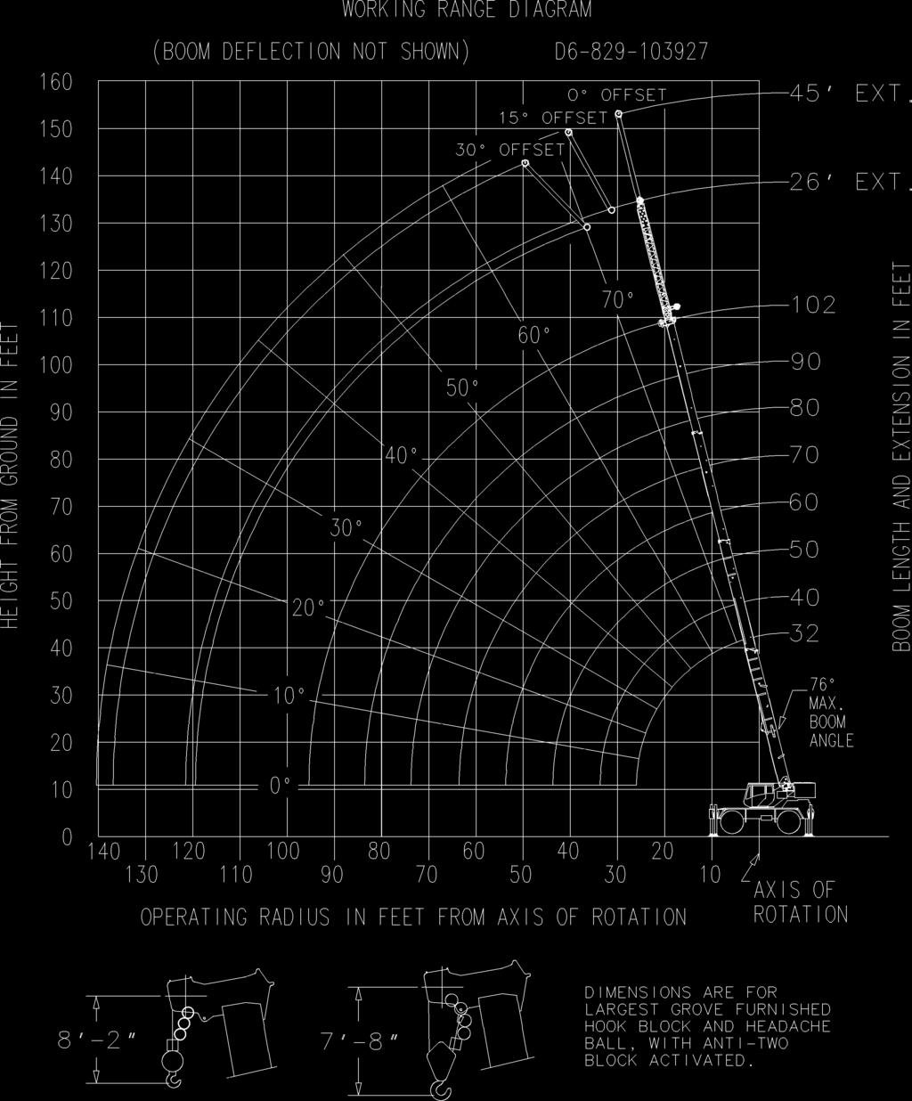
LOAD CHARTS RT540E 85% STABILITY ON OUTRIGGERS 75% STABILITY ON RUBBER
|
|
|
- Randolph Lester
- 5 years ago
- Views:
Transcription
1 LOAD CHARTS RT540E 85% STABILITY ON OUTRIGGERS 75% STABILITY ON RUBBER SERIAL NUMBER 1
2 2
3 TABLE OF CONTENTS GENERAL NOTES... 4 WT. REDUCTIONS / LINE PULLS & REEVING INFO / HOIST PERFORMANCE. 5 LIFTING AREA DIAGRAMS... 6 RANGE DIAGRAM w/ FIXED EXTENSION... 7 RANGE DIAGRAM w/ TELE EXTENSION... 8 ON OUTRIGGERS FULLY EXTENDED MAIN BOOM... 9 FIXED EXTENSION TELE EXTENSION ON RUBBER ON OUTRIGGERS 50% EXTENDED MAIN BOOM FIXED EXTENSION TELE EXTENSION ON OUTRIGGERS 0% EXTENDED MAIN BOOM TIRE INFLATION
4 NOTES FOR LIFTING CAPACITIES GENERAL: 1. Rated loads as shown on lift chart pertain to this machine as originally manufactured and equipped. Modifications to the machine or use of optional equipment other than that specified can result in a reduction of capacity. 2. Construction equipment can be hazardous if improperly operated or maintained. Operation and maintenance of this machine shall be in compliance with the information in the Operator s and Safety Handbook, Service Manual and Parts Manual supplied with this machine. If these manuals are missing, order replacements from the manufacturer through the distributor. 3. The operator and other personnel associated with machine shall fully acquaint themselves with the latest American National Safety Standards (ASME/ANSI) for cranes. SETUP: 1. The machine shall be level and on a firm supporting surface. Depending on the nature of the supporting surface, it may be necessary to have structural supports under the outrigger floats or tires to spread the load to a larger bearing surface. 2. For outrigger operation, all outriggers shall be properly extended with tires raised free of crane weight before operating the boom or lifting loads. 3. When machine is equipped with center front stabilizer, the front stabilizer shall be set in accordance with instructions in Operator's and Safety Handbook. 4. When equipped with removable and/or extendible counterweight, the proper counterweight shall be installed and fully extended before and during operation. 5. Tires shall be inflated to the recommended pressure before lifting on rubber. 6. With certain boom and hoist tackle combinations, maximum capacities may not be obtainable with standard cable lengths. 7. Unless approved by the crane manufacturer, do not travel with boom extension or jib erected unless otherwise noted. Refer to Operator's and Safety Handbook for job-site travel information. OPERATION: 1. Rated loads at rated radius shall not be exceeded. Do not attempt to tip the machine to determine allowable loads. For clamshell, grapple, magnet or concrete bucket operation, weight of component and load must not exceed 80% of rated lifting capacities. 2. All rated loads have been tested to and meet the requirements of SAE J Cantilevered Boom Crane Structures - Method of Test, and do not exceed 85% of the tipping load on outriggers fully extended, and SAE J Mobile Crane Stability Ratings [1.25P < (T- 0.1A)] on outriggers 50% and 0% extended (fully retracted) as determined by SAE J765 - Crane Stability Test Code. 3. Rated loads include the weight of hookblock, slings and auxiliary lifting devices and their weights shall be subtracted from the listed rating to obtain the net load to be lifted. When more than the minimum required parts of line needed to pick the load are used, the additional rope weight as measured from the lower sheaves of the the main boom nose shall be considered part of the load to be lifted. When both the hook block and headache ball are reeved, the lifting device that is NOT in use, including the line as measured from the lower sheave(s) of the nose supporting the unused device shall be considered part of the load. 4. Load ratings are based on freely suspended loads. No attempt shall be made to move a load horizontally on the ground in any direction. 5. The maximum in-service wind speed is 20 m.p.h. It is recommended when wind velocity is above 20 m.p.h., rated loads and boom lengths shall be appropriately reduced. For machines not in-service, the main boom should be retracted and lowered with the swing brake set in wind velocities over 30 m.p.h. 6. Rated loads are for lift crane service only. 7. Do not operate at a radius or boom length where capacities are not listed. At these positions, the machine may overturn without any load on the hook. 8. The maximum load which can be telescoped is not definable because of variations in loadings and crane maintenance, but it is safe to attempt retraction and extension of the boom within the limits of the capacity chart. 9. When the boom length or lift radius or both are between values listed, the smallest load shown at either the next larger radius or next longer or shorter boom length shall be used. 10. For safe operation, the user shall make due allowances for his particular job conditions, such as: soft or uneven ground, out of level conditions, high winds, side loads, pendulum action, jerking or sudden stopping of loads, experience of personnel, two machine (tandem) lifts, traveling with loads, electric wires, obstacles, hazardous conditions, etc. Side pull on boom or jib is extremely dangerous. 11. If machine is equipped with individually controlled powered boom sections, the boom sections must be extended equally at all times. 12. Never handle personnel with this machine unless the requirements of the applicable national, state, and local regulations and safety codes are met. 13. Keep load handling devices a minimum of 42 inches below boom head at all times. 14. The boom angle before loading should be greater than the loaded boom angle to account for deflection. 15. Capacities appearing above the bold line are based on structural strength and tipping should not be relied upon as a capacity limitation. 16. Capacities for the 32 ft. boom length shall be lifted with boom fully retracted. If boom is not fully retracted, capacities shall not exceed those shown for the 40 ft. boom length. 17. When operating the machine in the "On Outriggers 50% Extended (14' spread)" mode, the outrigger beam pins must be engaged. When operating in the "On Outriggers 0% Extended (7.8' spread)" mode, the outrigger beams must be fully retracted. Failure to follow these precautions could result in structural damage or loss of stability of the machine. 18. Regardless of counterweight and outrigger spread configuration, no deduct is required from the main boom charts for a stowed boom extension. 19. Do not lift loads when boom is fully lowered. The Load Moment Indicator (LMI) senses pressure and will not provide warnings or lockout. The crane can become overloaded if lift cylinder(s) is fully retracted. 20. The maximum outrigger pad load is 59,000 lb. DEFINITIONS: 1. Operating Radius: Horizontal distance from a projection of the axis of rotation to the supporting surface before loading to the center of the vertical hoist line or tackle with load applied. 2. Loaded Boom Angle (Shown in Parenthesis on Main Boom Capacity Chart): is the angle between the boom base section and the horizontal, after lifting the rated load at the rated radius with the rated boom length. 3. Working Area: Areas measured in a circular arc about the center line of rotation as shown on the working area diagram. 4. Freely Suspended Load: Load hanging free with no direct external force applied except by the lift cable. 5. Side Load: Horizontal force applied to the lifted load either on the ground or in the air. 4
5 WEIGHT REDUCTIONS FOR LOAD HANDLING DEVICES 26 FT. FIXED BOOM EXTENSION *Erected - 2,750 lb. 26 FT FT. TELE. BOOM EXTENSION *Erected (Retracted) - 3,750 lb. *Erected (Extended) - 5,010 lb. *Reduction of main boom capacities When lifting over boom extension, deduct total weight of all load handling devices reeved over main boom nose directly from boom extension capacity. NOTE: All load handling devices and boom attachments are considered part of the load and suitable allowances MUST BE MADE for their combined weights. Weights are for Grove furnished equipment. AUXILIARY BOOM NOSE 105 lb. HOOKBLOCKS and HEADACHE BALLS: 35 Ton, 3 Sheave (14" sheave) 623 lb.+ 35 Ton, 3 Sheave (12" sheave) 599 lb.+ 35 Ton, 4 Sheave (CE) 774 lb Ton Overhaul Ball 369 lb.+ +Refer to rating plate for actual weight. LINE PULLS AND REEVING INFORMATION HOISTS Main Main & Aux. CABLE SPECS. PERMISSIBLE LINE PULLS NOMINAL CABLE LENGTH 5/8" (16 mm) 6x37 Class, EIPS, IWRC Special Flexible Min. Breaking Strength 41,200 lb. 11,640 lb. 450 ft. 5/8" (16 mm) Flex-X 35 Rotation Resistant (Non-rotating) 11,640 lb. 450 ft. Min. Breaking Strength 61,200 lb. The approximate weight of 5/8" wire rope is 1.0 lb./ft. Wire Rope Layer HOIST PERFORMANCE Hoist Line Pulls Drum Rope Two Speed Hoist Capacity (ft.) Low High Available lb.* Available lb.* Layer Total 1 11,640 7, ,480 6, ,530 6, ,730 5, ,060 5, ,490 4, *Max. lifting capacity: 6x37 and 35x7 class = 11,640 lb. 5
6 6
7 7
8 8
9 Radius in Feet RATED LIFTING CAPACITIES IN POUNDS 32 FT FT. BOOM ON OUTRIGGERS FULLY EXTENDED - 36 # ,000 (69) 72,200 61,000 (61) 47,950 (54) 34,550 (41) 26,300 (20.5) See Note 16 50,700 50,700 48,400 35,000 (53.5) 26,800 (43.5) 21,250 (30) 48,500 (75) 48,500 48,500 (69) 35,400 27,200 (55.5) 21,650 (47.5) 17,650 (38.5) 14,400 (26.5) *46,400 44,300 (73) 35,300 27,400 21,850 (56.5) 17,900 (50.5) 14,450 (43.5) 11,650 (35) 9,480 (24.5) *38,700 31,000 (71.5) 25,800 (67) 21,800 18,050 (57.5) 14,650 (52.5) 11,800 (46.5) 9,680 (40.5) 7,970 (33) 6,600 (23) 29,700 (74) 24,600 20,800 (66.5) 17,800 14,800 (58.5) 11,900 (54) 9,770 (49) 8,080 (44) 6,720 (38) 5,590 (31) 4,640 (21.5) *22,000 22,000 (73) 18,350 (69.5) 15,600 (66) 13,500 11,750 9,780 (55) 8,110 (51) 6,770 (46.5) 5,670 (42) 4,740 (36) 3,940 (29.5) 3,250 (21) *18,500 17,500 (73) 15,200 13,200 (66.5) 11,600 (63.5) 9,790 (60.5) 8,130 (57) 6,800 (53.5) 5,710 (49.5) 4,800 (45.5) 4,040 (41) 3,360 (36) 2,770 (30.5) 2,250 (23) 1,800 (9.5) Minimum boom angle ( ) for indicated length (no load) 0 Maximum boom length (ft.) at boom angle (no load) 102 NOTE: ( ) Boom angles are in degrees. #LMI operating code. Refer to LMI manual for operating instructions. *This capacity is based on maximum boom angle. Lifting Capacities at Zero Degree Boom Angle Boom Angle ,950 (26) 18,100 (33.8) NOTE: ( ) Reference radii in feet. 12,150 (43.8) 8,180 (53.8) 5,740 (63.8) 4,030 (73.8) 2,800 (83.8) 1,760 (95.5) A
10 26 FT. FIXED TABLE EXTENSION ON OUTRIGGERS FULLY EXTENDED - 36 Radius in Feet Min. boom angle for indicated length (no load) Max. boom length at boom angle (no load) 26 ft. LENGTH #0051 #0053 *8,200 8,200 8,200 8,150 7,500 6,440 5,460 (60) 4,620 (57.5) 3,900 (54.5) 3,260 (51.5) 2,710 (48.5) 2,210 (45) 1,770 (41.5) 1,380 (38) 1,020 (33.5) 3 *5,780 5,780 5,450 4,910 4,450 (64.5) 4,050 (62) 3,670 3,350 (56) 3,100 (53) 2,580 (49.5) 2,080 (46) 1,620 (41.5) 1,200 (37) ft. A NOTE: ( ) Boom angles are in degrees. #LMI operating code. Refer to LMI manual for instructions. *This capacity based on maximum boom angle. BOOM EXTENSION CAPACITY NOTES: 1. All capacities above the bold line are based on structural strength of boom extension ft. fixed extension length may be used for single line lifting service. 3. Radii listed are for a fully extended boom with the boom extension erected. For main boom lengths less than fully extended, the rated loads are determined by boom angle. Use only the column which corresponds to the boom extension length and offset for which the machine is configured. For boom angles not shown, use the rating of the next lower boom angle. WARNING: Operation of this machine with heavier loads than the capacities listed is strictly prohibited. Machine tipping with boom extension occurs rapidly and without advance warning. 4. Boom angle is the angle above or below horizontal of the longitudinal axis of the boom base section after lifting rated load. 5. Capacities listed are with outriggers properly extended and vertical jacks set only. 6. When lifting over the main boom nose with 26 ft. fixed extension erected, the outriggers must be fully extended or 50% extended (14 spread). 10
11 26 FT FT. TELE TABLE BOOM EXTENSION ON OUTRIGGERS FULLY EXTENDED - 36 Radius in Feet ft. LENGTH 45 ft. LENGTH #0021 #0022 #0023 #0041 #0042 #0043 *10,200 9,460 8,760 8,150 7,510 6,700 5,990 (60) 5,240 (57.5) 4,400 (54.5) 3,670 (51.5) 3,050 (48.5) 2,500 (45) 2,020 (41.5) 1,590 (38) 1,200 (33.5) 15 *7,770 7,370 (72) 6,870 (69.5) 6,050 (67) 5,350 (64.5) 4,740 (62) 4,210 3,750 (56) 3,330 (53.5) 2,960 (50.5) 2,590 (47) 2,130 (43.5) 1,680 (40) 1,280 (35.5) 3 *6,030 5,780 5,520 5,290 4,810 (64.5) 4,270 (62) 3,800 3,380 (56) 3,010 (53) 2,670 (49.5) 2,270 (46) 1,790 (41.5) 1,360 (37) *5,250 5,250 (73.5) 5,050 (71.5) 4,650 (69.5) 4,290 (67) 4,000 3,800 (63) 3,650 (60.5) 3,520 (58.5) 3,360 (56) 3,030 (53.5) 2,640 (51) 2,270 (48) 1,930 (45.5) 1,630 (42.5) 1,330 (39) 1,040 (35.5) 15 3,660 3,540 3,430 3,320 (68.5) 3,220 (66) 3,130 (64) 3,000 (61.5) 2,880 2,770 (56.5) 2,680 (54) 2,570 (51.5) 2,260 (48.5) 1,890 (45.5) 1,550 (42) 1,240 (38.5) 3 *3,000 2,890 2,790 2,700 (68) 2,620 (65.5) 2,550 (63) 2,480 (60.5) 2,410 (57.5) 2,380 (55) 2,310 (52) 2,030 (48.5) 1,700 (45) 1,400 (41) 1,080 (36.5) Min. boom angle for indicated length (no load) Max. boom length at boom angle (no load) 80 ft. 80 ft. NOTE: ( ) Boom angles are in degrees. A #LMI operating code. Refer to LMI manual for instructions. *This capacity based on maximum boom angle. BOOM EXTENSION CAPACITY NOTES: 1. All capacities above the bold line are based on structural strength of boom extension ft. and 45 ft. tele extension lengths may be used for single line lifting service. 3. Radii listed are for a fully extended boom with the boom extension erected. For main boom lengths less than fully extended, the rated loads are determined by boom angle. Use only the column which corresponds to the boom extension length and offset for which the machine is configured. For boom angles not shown, use the rating of the next lower boom angle. WARNING: Operation of this machine with heavier loads than the capacities listed is strictly prohibited. Machine tipping with boom extension occurs rapidly and without advance warning. 4. Boom angle is the angle above or below horizontal of the longitudinal axis of the boom base section after lifting rated load. 5. Capacities listed are with outriggers properly extended and vertical jacks set only. 6. When lifting over the main boom nose with 26 ft. or 45 ft. tele extension erected, the outriggers must be fully extended or 50% extended (14 spread). 11
12 Radius in Feet ON RUBBER CAPACITIES STATIONARY CAPACITIES - 36 # ,050 21,600 (61) 15,250 (54) 9,110 (41) 5,790 (20) 24,100 22,050 15,550 9,380 (53.5) 6,050 (43) 3,970 (29.5) 23,000 21,600 16,100 (68.5) 9,860 (62) 6,400 (55) 4,240 (47.5) 2,770 (38) 1,690 (26) 13,900 9,860 6,510 (62) 4,370 (56) 2,900 (50) 1,840 (43) 1,030 (34.5) Minimum boom angle ( ) for indicated 33 length (no load) Maximum boom length (ft.) at boom 50 angle (no load) NOTE: ( ) Boom angles are in degrees. #LMI operating code. Refer to LMI manual for operating instructions. Lifting Capacities at Zero Degree Boom Angle Boom Angle ,290 (26) 2,850 (33.8) NOTE: ( ) Reference radii in feet. 1,060 (43.8) A
13 ON RUBBER CAPACITIES (cont'd.) PICK & CARRY CAPACITIES (UP TO 2.5 MPH) - BOOM CENTERED OVER FRONT (See note 6) Radius in Feet # ,150 23,350 (61) 18,950 (54) 13,700 (41) 10,100 (20) 26,900 23,250 19,100 14,200 (53.5) 10,750 (43.5) 8,290 (30) 19,400 (69) 14,500 11,150 (55.5) 8,620 (47.5) 6,710 (38.5) 5,210 (26.5) Minimum boom angle ( ) for indicated length (no load) Maximum boom length (ft.) at boom angle (no load) NOTE: ( ) Boom angles are in degrees. #LMI operating code. Refer to LMI manual for operating instructions. 14,550 11,200 (62) 8,790 (56.5) 6,890 (50) 5,390 (43) 4,180 (35) 3,190 (24) 0 60 Lifting Capacities at Zero Degree Boom Angle Boom Angle ,520 (26) 6,830 (33.8) NOTE: ( ) Reference radii in feet. 4,280 (43.8) 2,560 (53.8) A NOTES TO ALL RUBBER CAPACITY CHARTS: 1. Capacities are in pounds and do not exceed 75% of tipping loads as determined by test in accordance with SAE J Capacities are applicable to machines equipped with 20.5x25 (24 ply) tires at 75 psi cold inflation pressure, and 16.00x25 (28 ply) tires at 100 psi cold inflation pressure. 3. Capacities appearing above the bold line are based on structural strength and tipping should not be relied upon as a capacity limitation. 4. Capacities are applicable only with machine on firm level surface. 5. On rubber lifting with boom extensions not permitted. 6. For pick and carry operation, boom must be centered over front of machine, mechanical swing lock engaged and load restrained from swinging. When handling loads in the structural range with capacities close to maximum ratings, travel should be reduced to creep speeds. 7. Axle lockouts must be functioning when lifting on rubber. 8. All lifting depends on proper tire inflation, capacity and condition. Capacities must be reduced for lower tire inflation pressures. See lifting capacity chart for tire used. Damaged tires are hazardous to safe operation of crane. 9. Creep - not over 200 ft. of movement in any 30 minute period and not exceeding 1 mph. 13
14 Radius in Feet RATED LIFTING CAPACITIES IN POUNDS 32 FT FT. BOOM ON OUTRIGGERS 50% EXTENDED (14 ft. spread) - 36 # ,000 (69) 66,250 57,950 (61) 46,300 (54) 27,100 (41) 17,650 (20.5) See Note 16 50,700 50,700 44,200 27,700 (53.5) 18,250 (43.5) 12,850 (30) 48,500 (75) 48,500 41,800 (69) 27,050 18,500 (55.5) 13,200 (47.5) 9,790 (38.5) 7,400 (26.5) *46,400 39,550 (73) 25,950 18,450 13,300 (56.5) 9,910 (50.5) 7,520 (43.5) 5,760 (35) 4,410 (24.5) *37,550 24,950 (71.5) 18,050 (67) 13,550 10,150 (57.5) 7,770 (52.5) 5,970 (46.5) 4,590 (40.5) 3,500 (33) 2,610 (23) 24,000 (74) 17,450 13,250 (66.5) 10,250 7,910 (58.5) 6,150 (54) 4,750 (49) 3,630 (44) 2,730 (38) 1,980 (31) 1,350 (21.5) *22,000 16,950 (73) 12,950 (69.5) 10,100 (66) 7,950 6,180 4,820 (55) 3,710 (51) 2,810 (46.5) 2,070 (42) 1,440 (36) *16,350 12,500 (73) 9,830 7,820 (66.5) 6,190 (63.5) 4,850 (60.5) 3,780 (57) 2,890 (53.5) 2,150 (49.5) 1,530 (45.5) 1,000 (41) Minimum boom angle ( ) for indicated length (no load) Maximum boom length (ft.) at boom angle (no load) 80 NOTE: ( ) Boom angles are in degrees. #LMI operating code. Refer to LMI manual for operating instructions. *This capacity is based on maximum boom angle. Lifting Capacities at Zero Degree Boom Angle Boom Angle ,300 (26) 10,150 (33.8) NOTE: ( ) Reference radii in feet. 6,030 (43.8) 3,580 (53.8) 2,050 (63.8) A
15 26 FT. FIXED TABLE EXTENSION ON OUTRIGGERS 50% EXTENDED (14 ft. spread) - 36 Radius in Feet Min. boom angle for indicated length (no load) Max. boom length at boom angle (no load) 26 ft. LENGTH #4051 #4053 *8,200 7,240 5,780 4,610 3,650 2,850 2,140 (60) 1,540 (57.5) 1,030 (54.5) 3 *5,780 5,740 4,650 3,720 2,900 (64.5) 2,210 (62) 1,620 1,100 (56) ft. A NOTE: ( ) Boom angles are in degrees. #LMI operating code. Refer to LMI manual for instructions. *This capacity based on maximum boom angle. BOOM EXTENSION CAPACITY NOTES: 1. All capacities above the bold line are based on structural strength of boom extension ft. fixed extension length may be used for single line lifting service. 3. Radii listed are for a fully extended boom with the boom extension erected. For main boom lengths less than fully extended, the rated loads are determined by boom angle. Use only the column which corresponds to the boom extension length and offset for which the machine is configured. For boom angles not shown, use the rating of the next lower boom angle. WARNING: Operation of this machine with heavier loads than the capacities listed is strictly prohibited. Machine tipping with boom extension occurs rapidly and without advance warning. 4. Boom angle is the angle above or below horizontal of the longitudinal axis of the boom base section after lifting rated load. 5. Capacities listed are with outriggers properly extended and vertical jacks set only. 6. When lifting over the main boom nose with 26 ft. fixed extension erected, the outriggers must be fully extended or 50% extended (14 spread). 15
16 26 FT FT. TELE BOOM EXTENSION ON OUTRIGGERS 50% EXTENDED (14 ft. spread) - 36 Radius in Feet ft. LENGTH 45 ft. LENGTH #4021 #4022 #4023 #4041 #4042 #4043 *9,120 7,240 5,780 4,610 3,650 2,850 2,140 (60) 1,540 (57.5) 1,030 (54.5) 15 *7,770 6,460 (72) 5,200 (69.5) 4,180 (67) 3,320 (64.5) 2,550 (62) 1,900 1,350 (56) 3 *6,030 5,740 4,650 3,720 2,900 (64.5) 2,210 (62) 1,620 1,100 (56) *5,250 5,250 (73.5) 5,050 (71.5) 4,280 (69.5) 3,480 (67) 2,820 2,260 (63) 1,740 (60.5) 1,300 (58.5) 15 3,660 3,540 3,430 3,320 (68.5) 2,880 (66) 2,300 (64) 1,800 (61.5) 1,360 3 *3,000 2,890 2,790 2,700 (68) 2,240 (65.5) 1,750 (63) 1,320 (60.5) Min. boom angle for indicated length (no load) Max. boom length at boom angle (no load) 60 ft. 60 ft. NOTE: ( ) Boom angles are in degrees. A #LMI operating code. Refer to LMI manual for instructions. *This capacity based on maximum boom angle. BOOM EXTENSION CAPACITY NOTES: 1. All capacities above the bold line are based on structural strength of boom extension ft. and 45 ft. tele extension lengths may be used for single line lifting service. 3. Radii listed are for a fully extended boom with the boom extension erected. For main boom lengths less than fully extended, the rated loads are determined by boom angle. Use only the column which corresponds to the boom extension length and offset for which the machine is configured. For boom angles not shown, use the rating of the next lower boom angle. WARNING: Operation of this machine with heavier loads than the capacities listed is strictly prohibited. Machine tipping with boom extension occurs rapidly and without advance warning. 4. Boom angle is the angle above or below horizontal of the longitudinal axis of the boom base section after lifting rated load. 5. Capacities listed are with outriggers properly extended and vertical jacks set only 6. When lifting over the main boom nose with 26 ft. or 45 ft. tele extension erected, the outriggers must be fully extended or 50% extended (14 spread). 16
17 RATED LIFTING CAPACITIES IN POUNDS 32 FT FT. BOOM Radius in Feet ON OUTRIGGERS 0% EXTENDED (7.8 ft. spread) - 36 # ,950 (69) 37,800 29,050 (61) 20,850 (54) 12,500 (41) 7,950 (20.5) See Note 16 35,900 28,100 20,450 13,050 (53.5) 8,460 (43.5) 5,610 (30) 33,600 (75) 26,600 19,750 (69) 12,950 8,700 (55.5) 5,890 (47.5) 3,980 (38.5) 2,600 (26.5) *25,150 18,850 (73) 12,600 8,760 6,000 (56.5) 4,090 (50.5) 2,710 (43.5) 1,670 (35) *18,000 12,150 (71.5) 8,580 (67) 6,110 4,350 (57.5) 2,940 (52.5) 1,860 (46.5) 1,020 (40.5) 11,700 (74) 8,300 5,980 (66.5) 4,270 2,970 (58.5) 1,960 (54) 1,160 (49) *11,250 8,050 (73) 5,840 (69.5) 4,200 (66) 2,940 1,950 1,160 (55) *7,720 5,600 (73) 4,060 2,850 (66.5) 1,890 (63.5) 1,110 (60.5) Minimum boom angle ( ) for indicated length (no load) Maximum boom length (ft.) at boom angle (no load) 60 NOTE: ( ) Boom angles are in degrees. #LMI operating code. Refer to LMI manual for operating instructions. *This capacity is based on maximum boom angle. Lifting Capacities at Zero Degree Boom Angle Boom Angle ,230 (26) 4,060 (33.8) NOTE: ( ) Reference radii in feet. 1,790 (43.8) A
18 TIRE INFLATION - PSI (BAR) SIZE (FRONT & REAR) LOAD RANGE TRA CODE LIFTING SERVICE AND GENERAL TRAVEL STATIC, CREEP & 2.5 MPH (4.0 km/h) EXTENDED TRAVEL 20.5x25 24 PR E-3 75 (5.2) 70 (4.8) 16.00x25 28 PR E (6.9) 95 (6.6) 18
LOAD CHARTS RT890E METRIC DIN / ISO / 75%
 LOAD CHARTS RT89E METRIC DIN / ISO / 75% 232729 SERIAL NUMBER RT89E - S/N 232729 1 RT89E - S/N 232729 2 TABLE OF CONTENTS GENERAL NOTES...4 WEIGHT REDUCTIONS / LINE PULLS & REEVING INFO / RIGGING CHART
GROVE MODEL RT58D - 20 TON CAPACITY
 LIFTING CHARTS - Rough Terrain Cranes GROVE MODEL - 20 TON CAPACITY WEIGHT REDUCTIONS FOR LOAD HANDLING DEVICES 23 JIB with 28-70 BOOM * Stowed - 381 lbs. * Erected - 1,950 lbs. 23-38 TELE. JIB with 28-70
LOAD CHARTS RT640C 85% STABILITY ON OUTRIGGERS 75% STABILITY ON RUBBER
 LOAD CHARTS RT6C 85% STABILITY ON OUTRIGGERS 75% STABILITY ON RUBBER SERIAL NUMBER 1 NOTES FOR LIFTING CAPACITIES GENERAL: 1. Rated loads as shown on lift chart perta to this mache as origally manufactured
Grove RT9130E-2. Product Guide. Features. View thousands of Crane Specifications on FreeCraneSpecs.com. 120 t (130 USt) capacity
 capacity") Grove RT9E-2 Product Guide Features 120 t ( USt) capacity 12,8 m - 48,8 m (42 ft - 160 ft) five-section, full power boom 11 m -18 m (36 ft - 59 ft) offsettable bi-fold swingaway extension 8 m (26 ft) extension
Grove RT9E-2 Product Guide Features 120 t ( USt) capacity 12,8 m - 48,8 m (42 ft - 160 ft) five-section, full power boom 11 m -18 m (36 ft - 59 ft) offsettable bi-fold swingaway extension 8 m (26 ft) extension
RT890E. product guide. contents Features 2. features. Rough Terrain Hydraulic Crane. Specifications 3. Dimensions & Weights 5.
 product guide features 90 Ton (80 mt) Capacity 38 ft.-142 ft. (11.6-43.3 m) 5 Section, Full Power Boom 33 ft.-56 ft. (10.1-17 m) Offsettable Bi-fold Lattice, Swingaway Extension 16 ft. (4.8 m) or 32 ft.
RT890E. product guide. contents. features. Rough Terrain Hydraulic Crane. Features 2. Specifications 3. Dimensions & Weights 5.
 product guide features 90 Ton (80 mt) Capacity 38 ft.-142 ft. (11.6-43.3 m) 5 Section, Full Power Boom 33 ft.-56 ft. (10.1-17 m) Offsettable Bi-fold Lattice, Swingaway Extension 16 ft. (4.8 m) or 32 ft.
Grove TMS800E Product Guide
 Grove TMS0E Product Guide Features 12,6 m - 39 m (41 ft - 128 ft) four-section full power MEGAFORM boom 10 m 17 m (33 ft 56 ft) manual offset bifold swingaway 2 x 20 ft intermediate lattice inserts 10
Grove RT9130E. Product Guide. Features. 120 t (130 USt) capacity. 12,8 m - 48,8 m (42 ft ft) five-section, full power boom
 capacity. 12,8 m - 48,8 m (42 ft ft) five-section, full power boom") Grove RT9130E Product Guide Features 120 t (130 USt) capacity 12,8 m - 48,8 m (42 ft - 160 ft) five-section, full power boom 11 m -18 m (36 ft - 59 ft) offsettable bi-fold swingaway extension 8 m (26 ft)
Grove RT9130E Product Guide Features 120 t (130 USt) capacity 12,8 m - 48,8 m (42 ft - 160 ft) five-section, full power boom 11 m -18 m (36 ft - 59 ft) offsettable bi-fold swingaway extension 8 m (26 ft)
RT9130E. product guide. contents. features. Rough Terrain Hydraulic Crane. Features 2. Specifications 3. Dimensions & Weights 5
 product guide features ton (120 mt) capacity 42-160 ft. (12.8-48.8 m) 5-section, full power boom 36-59 ft (11-18 m) offsettable bi-fold swingaway extension 26 ft. (8 m) extension inserts Grove MEGAFORM
Product Guide. Features. five-section, full power boom. bi-fold swingaway extension. 8 m (26 ft) extension inserts. Grove MEGAFORM boom.
 extension inserts. Grove MEGAFORM boom.") Grove RT9130E Product Guide Features 120 t (130 USt) capacity 12,8 m - 48,8 m (42 ft - 160 ft) five-section, full power boom 11 m -18 m (36 ft - 59 ft) offsettable bi-fold swingaway extension 8 m (26 ft)
Grove RT9130E Product Guide Features 120 t (130 USt) capacity 12,8 m - 48,8 m (42 ft - 160 ft) five-section, full power boom 11 m -18 m (36 ft - 59 ft) offsettable bi-fold swingaway extension 8 m (26 ft)
Grove RT9130E-2. Product Guide. Features. 120 t (130 USt) capacity. 12,8 m - 48,8 m (42 ft ft) five-section, full power boom
 capacity. 12,8 m - 48,8 m (42 ft ft) five-section, full power boom") Grove RT9E-2 Product Guide Features t ( USt) capacity 12,8 m - 48,8 m (42 ft - ft) five-section, full power boom 11 m -18 m (36 ft - 59 ft) offsettable bi-fold swingaway extension 8 m (26 ft) extension
Grove RT9E-2 Product Guide Features t ( USt) capacity 12,8 m - 48,8 m (42 ft - ft) five-section, full power boom 11 m -18 m (36 ft - 59 ft) offsettable bi-fold swingaway extension 8 m (26 ft) extension
Crane Rental Heavy Machinery Moving Project Management
 2 3 4 5 6 7 8 9 10 Link-Belt TG-2300B lifting crane capabilities - heavy duty boom Boom - tubular: 90" x 90" (2.29 x 2.29 m) with open throat top section, 2" (51 mm) diameter boom pendants. Mast - 43'
GRT8100 Product Guide
 GRT8 Product Guide ANSI B30.5 Imperial 85% Features 90 t ( USt) capacity 12 m 47 m (39.2 ft 154.3 ft) five-section full-power boom 10 m 17 m (33 ft 56 ft) manual offsettable bi-fold lattice swingaway extension
6000SLX HYDRAULIC CRAWLER CRANE
 HYDRAULIC CRAWLER CRANE HYDRAULIC CRAWLER CRANE Contents Specifications 3-4 Symbols 4 Outline Winch Assingment 5 Dimensions & Main Specifications : Liftcrane 6 Dimensions & Main Specifications : Luffing
Grove RT890E. Product Guide. Features. 80 t (90 USt) capacity. 11,4 m 43,2 m (38 ft 142 ft) 5-section, full power boom
 capacity. 11,4 m 43,2 m (38 ft 142 ft) 5-section, full power boom") Grove RT890E Product Guide Features 80 t (90 USt) capacity 11,4 m 43,2 m (38 ft 142 ft) 5-section, full power boom 10 m 17 m (33 ft 56 ft) offsettable bi-fold lattice, swingaway extension 4,8 m (16 ft)
Grove RT890E Product Guide Features 80 t (90 USt) capacity 11,4 m 43,2 m (38 ft 142 ft) 5-section, full power boom 10 m 17 m (33 ft 56 ft) offsettable bi-fold lattice, swingaway extension 4,8 m (16 ft)
Grove RT890E. Product Guide. Features. 80 t (90 USt) capacity. 11,4 m 43,2 m (38 ft 142 ft) five-section, full power boom
 capacity. 11,4 m 43,2 m (38 ft 142 ft) five-section, full power boom") Grove RT890E Product Guide Features 80 t (90 USt) capacity 11,4 m 43,2 m (38 ft 142 ft) five-section, full power boom 10 m 17 m (33 ft 56 ft) offsettable bi-fold lattice, swingaway extension 4,8 m (16
Grove RT890E Product Guide Features 80 t (90 USt) capacity 11,4 m 43,2 m (38 ft 142 ft) five-section, full power boom 10 m 17 m (33 ft 56 ft) offsettable bi-fold lattice, swingaway extension 4,8 m (16
6000SLX SL-N HYDRAULIC CRAWLER CRANE
 SL-N SL-N HYDRAULIC CRAWLER CRANE 1804 05H.EA292 SL-N Specifications Contents Specifications 3-4 Symbols 4 Outline Winch Assignment 5 Dimensions & Main Specifications : Liftcrane 6 Dimensions & Main Specifications
MANITOWOC MODEL TON CAPACITY
 LIFTING CHARTS - Crawler Cranes ANITOWOC ODEL - TON CAPACITY BOO RIGGING GUIDE ODEL # HEAVY LIFT BOO Table of Contents General... Assist Crane Requirements... Accessing Parts... Installation and Removal
National 400B. Certification CraneSafe Certification. CraneSafe + Fulford Harbour Group Tel:
 Load Chart PRACTICE Exercises Stiff TRUCK CRANE 40 Tonnes & under National 400B Stiff Boom Truck 40 Tonnes & Under PRACTICE EXERCISES LCR.SB40.NA400B.PE1 30 July 2009 + Fulford Harbour Group Tel: 604.952.6033
ALL TERRAIN CRANE AR-1200M-1
 ALL TERRAIN RANE AR-12M JAPANESE SPEIFIATIONS ARRIER MODEL FAUN RTF12-5 SPE. NO. AR-12M-1 AR ontrol No. JA-3-279 - Return to INDEX AR-12M RANE SPEIFIATIONS RANE APAITY 12.2m Boom 12,kg at 2.7m (17part-line)
Grove RT890E. Product Guide. Features. 80 t (90 USt) capacity. 11,4 m 43,2 m (38 ft 142 ft) five-section, full power boom
 capacity. 11,4 m 43,2 m (38 ft 142 ft) five-section, full power boom") Grove RT890E Product Guide Features 80 t (90 USt) capacity 11,4 m 43,2 m (38 ft 142 ft) five-section, full power boom 10 m 17 m (33 ft 56 ft) offsettable bi-fold lattice, swingaway extension 4,8 m (16
Grove RT890E Product Guide Features 80 t (90 USt) capacity 11,4 m 43,2 m (38 ft 142 ft) five-section, full power boom 10 m 17 m (33 ft 56 ft) offsettable bi-fold lattice, swingaway extension 4,8 m (16
View thousands of Crane Specifications on FreeCraneSpecs.com. MANITOWOC M-85W 95-Ton liftcrane 20,000 lb CLAMSHELL 18,000 lb DRAGLINE
 MANITOWOC M-85W 95-Ton liftcrane 20,000 lb CLAMSHELL 18,000 lb DRAGLINE 94 MANITOWOC M-85W Outline dimensions 95 MANITOWOC M-85W Performance data 96 MANITOWOC M-85W Shipping data (all dimensions length
Chapter 2 Rigging. Cutting Wire Rope. Anchoring Wire Rope to Drum. Winding Wire Rope Onto Drum
 Chapter 2 Rigging Cutting Wire Rope The wire rope must be tightly seized on both sides of the point where the wire rope will be cut, as shown in Figure 2-1. Seize the wire rope with either seizing wire
Key. counterweight. Lifting capacities on outriggers 360. Superlift
 Specifications Dimensions Lifting capacities main boom with Superlift Lifting capacities main boom Working ranges main boom Working ranges main boom extension Working ranges fixed fly jib Working ranges
M ANITOWOC M-65 W. 65-MTon liftcrane 6,804 6,124. Courtesy of Crane.Market KG CLAMSHELL KG DRAGLINE
 M ANITOWOC M-65 W 6,804 KG CLAMSHELL 6,124 65-MTon liftcrane KG DRAGLINE 45 M ANITOWOC M-65 W Outline dimensions 46 M ANITOWOC M-65 W Performance data 47 M ANITOWOC M-65 W Shipping data (all dimensions
Technical Data. Luffing Capacities. Luffing Attachment (supersedes 5784)-1217-U2Luffer
-1217-U2Luffer") 1 5802 (supersedes 5784)-1217-U2Luffer Technical Data Luffing Capacities Luffing Attachment CAUTION: This material is supplied for reference use only. Operator must refer to in-cab Crane Rating Manual
1 5802 (supersedes 5784)-1217-U2Luffer Technical Data Luffing Capacities Luffing Attachment CAUTION: This material is supplied for reference use only. Operator must refer to in-cab Crane Rating Manual
LR Technical data Hydraulic lift crane. Complies with ANSI B Courtesy of Crane.Market
 Technical data Hydraulic lift crane LR Complies with ANSI B 0.5 Dimensions Basic machine with undercarriage The operating weight includes the basic machine with crawlers, main winches,00 and ft main boom,
Technical data Hydraulic lift crane LR 1300 SX
 Technical data Hydraulic lift crane LR 1300 SX Dimensions Basic machine with undercarriage R 9750 30 10350 6930 3000 2250 10 5000 1465 1700 8500 9650 42 1870 10 00 0 R 69 1485 00 365 85 1500 8300 0 Operating
Technical data Hydraulic lift crane LR 1300 SX. Complies with ANSI/ASME B
 Technical data Hydraulic lift crane LR 1300 SX Complies with ANSI/ASME B 30.5 1006.01 Dimensions Basic machine with undercarriage R 32 11 10 34 22 9 9 10 7 5 5 3 16 5 57.7 5 7 27 11 31 8 14 6 2 47.2 26
View thousands of Crane Specifications on FreeCraneSpecs.com LR 1300 SX. Technical data Hydraulic lift crane LR 1300
 Technical data Hydraulic lift crane LR 1300 SX LR 1300 Dimensions Basic machine with undercarriage R 9750 30 10350 6930 3000 LR 1300 5000 2250 10 1465 1700 8500 9650 42 1870 10 00 0 R 69 Optional: Track
HYDRAULIC CRAWLER CRANE
 HYDRAULIC CRAWLER CRANE Max. Lifting Capacity: 440 US ton x 18 ft Max. Boom Length: 315 ft Max. Luffing jib Combinations: 256 ft + 217 ft CONFIGURATION STD Luffing Boom Max. Lifting Capacity: 881,0 lbs
Hydraulic lift crane. Complies with ANSI/ASME B 30.5 LR enus LR
 Hydraulic lift crane LR 1110 Complies with ANSI/ASME B 30.5 enus LR 1001.02 Concept and characteristics LR 1110 Standard Excellent lifting capacities thanks to optimized distribution of forces New cabin
LINK-BELT MODEL HC-278H TON CAPACITY
 TRANSPORTATION SPECS - Conventional Truck Cranes LINK-BELT MODEL HC-278H - 300 TON CAPACITY COMPONENT WEIGHTS LBS. KGS. BOOM TYPE: TUBULAR 80 X 68 LBS. KGS. Complete Crane C/W 70 Boom, 320,123 145 207
6000SLX SL-T HYDRAULIC CRAWLER CRANE
 SL-T SL-T HYDRAULIC CRAWLER CRANE 1804 05H.EA293 SL-T Specifications Contents Specifications 3-4 Symbols 4 Outline Winch Assignment 5 Dimensions & Main Specifications : Liftcrane 6 Dimensions & Main Specifications
CKE2500 HYDRAULIC CRAWLER CRANE GENERAL DIMENSIONS. Max. Lifting Capacity
 HYDRAULIC CRAWLER CRANE CKE Max. Lifting Capacity: 2 t Max. Boom Length: 91.4 m Max. Jib Combination: 76.2 +. m Max. Luffing Jib Combination: 1.8 + S P E C I F I C A T I O N S Main Boom Max. Lifting Capacity
Technical data Hydraulic lift crane. LR 1300 sx LR 1300
 Technical data Hydraulic lift crane LR 1300 sx LR 1300 Dimensions Basic machine with undercarriage R 9750 30 10350 6930 3000 LR 1300 2250 10 5000 1465 1700 8500 9650 42 1870 10 00 0 R 69 Optional: Flat
MANITOWOC MODEL TON CAPACITY
 LIFTING CHARTS - Crawler Cranes ANITOWOC ODEL - 0 TON CAPACITY BOO RIGGING GUIDE ODEL AND # EL BOO Table of Contents General... Assist Crane Requirements... Accessing Parts... Installation and Removal
HYDRAULIC CRAWLER CRANE
 HYDRAULIC CRAWLER CRANE Max. Lifting Capacity: 50 t x 4.6 m Max. Crane Length: 9.4 m Max. Fixed Jib Combination: 76. + 30.5 m Max. Luffing Jib Combination: + m CONFIGURATION Crane Max. Lifting Capacity:
HYDRAULIC CRAWLER CRANE
 HYDRAULIC CRAWLER CRANE Max. Lifting Capacity: 50 t x 4.6 m Max. Crane Length: 9.4 m Max. Fixed Jib Combination: 76. + 30.5 m Max. Luffing Jib Combination: + m CONFIGURATION Crane Max. Lifting Capacity:
Demag TC3000
 www.barnhartcrane.com Demag TC3000 550T 550T 550T Component Weights Weight of counterweighted Machine with 39' (12m) boom Superstructure only (with 4 drums, boom foot section and mast) Truck Carrier Outrigger
Product Guide. Crawler Crane
 Crawler Crane 220 US Tons (100 Metric Tons) @ 16 ft 5 in Radius 285 ft Max Tip (Main Boom) Main Boom, Fixed Jib and Luffing Jib Configurations Product Guide KEY FEATURES ULTRA CAB The Ultra Cab, designed
Hydraulic Crawler Crane
 Hydraulic Crawler Crane Model : SL00G Max. Lifting Capacity : 00 t x. m Max. Crane Boom Length : 96.0 m Max. Luffing Jib Combination: m + m CONFIGURATION STD Long Boom Max. Lifting Capacity: 113. metric
HYDRAULIC CRAWLER CRANE
 HYDRAULIC CRAWLER CRANE Max. Lifting Capacity: 00 ton x. m Max. Boom Length: m Max. Luffing Jib Combination: 78 m + CONFIGURATION STD Long Boom Max. Lifting Capacity: 113. metric tons x 10.0 m Max. Boom
Crane & Rigging Brain Teasers
 Crane & Rigging Brain Teasers Host: Mike Parnell President/CEO, ITI ASME B30 Vice Chair (Cranes & Rigging) ASME P30 Chair (Lift Planning) The views expressed in this presentation are that of ITI and are
RATED CAPACITY LIMITER SYSTEM DS 350 OPERATOR S HANDBOOK. DS350/1225/1229 Consoles HC 248H OPERATING CODES. Link-Belt. Construction Equipment
 RATED CAPACITY LIMITER SYSTEM DS 350 OPERATOR S HANDBOOK DS350/1225/1229 Consoles HC 248H OPERATING CODES Link-Belt Construction Equipment LATTICE BOOM CRANES RATED CAPACITY LIMITER SYSTEM DS 350 OPERATOR'S
Unit shown in luffer configuration
 Transport complete crane with base section, drums with rope and self assembly device, less counterweights at under 100,000 lbs (45 360 kg) Rated capacity limiter with full color graphic display Powerful
ALL TERRAIN CRANE GA-1500N
 ALL TERRAIN CRANE GA GA-N JAPANESE SPECIFICATIONS CARRIER MODEL SPEC. NO. FAUN RTF- GA-N--9 Control No. GA-N--9 / JA- - GA-N CRANE SPECIFICATIONS SINGLE TOP CRANE CAPACITY.m Boom,kg.m Boom.m Boom.m Boom.m
Puyuan. QUY 160 Crawler Crane Technical Manual
 Puyuan QUY 160 Crawler Crane Technical Manual 5 Pictures and technical parameters in sample books may not accord with the delivery goods because of the improvement in design. Please understand and make
Load Charts Annotated Instructor s Guide. Module MODULE OVERVIEW PREREQUISITES OBJECTIVES PERFORMANCE TASKS MATERIALS AND EQUIPMENT LIST
 Load Charts Annotated Instructor s Guide Module 21301-05 MODULE OVERVIEW This module discusses the importance of load charts and charts that apply to different configurations. It includes on-rubber, on-outrigger,
Heavy-duty power for the most demanding jobs
 110-ton (99.97 mt) Lattice Boom Crawler Crane Heavy-duty power for the most demanding jobs Transport complete crane with base section, drums with rope and self assembly device, less counterweights at under
CKE4000 HYDRAULIC CRAWLER CRANE GENERAL DIMENSIONS PRELIMINARY. Max. Lifting Capacity
 HYDRAULIC CRAWLER CRANE CKE4000 Max. Lifting Capacity: 350 t Max. Boom Length : 78.0 m Max. Luffing Jib Combination : 72.0 + 54.0 m PRELIMINARY S P E C I F I C A T I O N S Main Boom Max. Lifting Capacity
HYDRAULIC CRAWLER CRANE
 HYDRAULIC CRAWLER CRANE Max. Lifting Capacity: 135 t x 4.5 m Max. Crane oom Length: 76. m Max. Long oom Length: 8.3 m Max. Fixed Jib Combination: 61.0 m +.5 m Max. Luffing Jib Combination: 47.9 + 3.0 m,
Standard Equipment HYDRAULIC CRAWLER CRANE
 HYDRAULIC CRAWLER CRANE Standard Equipment Upper structure/lower structure Counterweight: 53.0 ton (total weight) Carbody weight:.0 ton (total weight) 9 mm shoe crawlers atteries (150 Ah/0 HR) rans-lifter
250 ton mt Lattice Crawler Crane
 250 ton 226.8 mt Lattice Crawler Crane Heavy duty combination top section for conventional and luffing jib configuration Bar pendants & boom walkway 320 hp Cummins QSL9 Tier IV Final Transport weight is
Lattice Boom Crawler Crane 300-ton (272 mt)
") Lattice Boom Crawler Crane 300-ton (272 mt) Wide or narrow gauge patented All hydraulic controls & power Dual cross-section main boom High performance matching main hoists with 28mm rope Tilt cab High
Lattice Boom Crawler Crane 300-ton (272 mt) Wide or narrow gauge patented All hydraulic controls & power Dual cross-section main boom High performance matching main hoists with 28mm rope Tilt cab High
Technical Data. Specifications & Capacities. HSL Crawler Crane. View thousands of Crane Specifications on FreeCraneSpecs.com
 5717 (supersedes 5666)-0315-N6 1 Technical Data Specifications & Capacities HSL Crawler Crane 110 Ton (99.8 metric ton) CAUTION: This material is supplied for reference use only. Operator must refer to
Crane Signal Person Basic Training Video Comprehension Assessment
 Crane Signal Person Basic Training Video Comprehension Assessment Name Date Circle the letter or letters for each correct answer. 1. Which of the following components are typically found on cranes? Choose
The purpose of this training is to give field technicians awareness training and guidelines on potential hazards they may encounter in the field.
 Purpose The purpose of this training is to give field technicians awareness training and guidelines on potential hazards they may encounter in the field. Fall Protection and Prevention JELD-WEN Field Employees
Premium PowerPoint Presentation. Rigging Review
 Premium PowerPoint Presentation Rigging Review Chapter 1 Hoisting Safety Review: What about the CG Symmetrical vs. Asymmetrical Balanced and Unbalanced Lifting Lug Hooks Angle Deformation Safety Gates
NAVSEA STANDARD ITEM. 1.1 Title: Contractor Crane, Multi-Purpose Machine and Material Handling Equipment at a Naval Facility; provide
 NAVSEA STANDARD ITEM ITEM NO: 009-40 DATE: 26 MARCH 2018 CATEGORY: I 1. SCOPE: 1.1 Title: Contractor Crane, Multi-Purpose Machine and Material Handling Equipment at a Naval Facility; provide 2. REFERENCES:
LIFTING PLAN PERMIT TO WORK RISK ASSESSMENT
 Code of Practice on Safe Lifting Operations at Workplaces LIFTING PLAN PERMIT TO WORK RISK ASSESSMENT Yeo Kim Hock 13 th December 2012 Introduction-Objectives of Lifting Plan/ PTW/ RA Fundamental Contents-
NAVSEA STANDARD ITEM
 NAVSEA STANDARD ITEM ITEM NO: 009-40 DATE: 18 JUL 2014 CATEGORY: I 1. SCOPE: 1.1 Title: Requirements for Contractor Cranes, Multi-Purpose Machines and Material Handling Equipment at Naval Facilities; accomplish
HYDRAULIC CRAWLER CRANE
 HYDRAULIC CRAWLER CRANE Max. Lifting Capacity: 0 t x m Max. oom Length: 6.0 m Max. Long oom Length: 79. m Max. Jib Combination: 6.0 + 30.5 m Max. Luffing Tower Combination: + 44. m CONFIGURATION Long oom
1. Outline of the newly developed control technologies
 This paper describes a vertical lifting control and level luffing control design for newly developed, fully hydraulicdriven floating cranes. Unlike lattice boom crawler cranes for land use, the floating
HYDRAULIC CRAWLER CRANE
 HYDRAULIC CRAWLER CRANE Max. Lifting Capacity: 90 t x m Max. oom Length: m Max. Jib Combination: 5 +.3 m Max. Luffing ower Combination: 4 + 37.m CONFIGURAION Main oom Max. Lifting Capacity: 90.0 metric
110-ton (99.97 mt) Lattice Boom Crawler Crane
 Lattice Boom Crawler Crane") 110-ton (99.97 mt) Lattice Boom Crawler Crane 110 ton (99.97 mt) Lattice Boom Crawler Crane Heavy-duty power for the most demanding jobs Robust engine with total horsepower control provides unbeatable
110-ton (99.97 mt) Lattice Boom Crawler Crane 110 ton (99.97 mt) Lattice Boom Crawler Crane Heavy-duty power for the most demanding jobs Robust engine with total horsepower control provides unbeatable
Heavy Equipment Technician Rigging
 1. What is SWL? a. Single weight of load b. Second weakest location c. Working load limit Heavy Equipment Technician IP Red Seal Practice Exam d. Abbreviation for swivel Heavy Equipment Technician Rigging
GUIDELINES FOR USE GUARD
 GUIDELINES FOR USE GUARD G Guard Range of Load Arrestors Retractable Fall Arrest Safety Line for Protection of Machinery & Sensitive Loads GLOBESTOCK MILE OAK INDUST. ESTATE, MAESBURY ROAD, OSWESTRY, SHROPSHIRE
data model 2250 product guide contents features 272 mton (300 ton) capacity mton-m (12,294 ft-kips) Maximum Load Moment
 capacity mton-m (12,294 ft-kips) Maximum Load Moment") data features 272 mton (300 ton) capacity 700 mton-m (2,294 ft-kips) Maximum Load Moment 9,4 m (300') Heavy-Lift 00,6 m (330') Long-Reach 2,8 m (370') Fixed Jib on Heavy-Lift 8,9 m (390') Fixed Jib on
data features 272 mton (300 ton) capacity 700 mton-m (2,294 ft-kips) Maximum Load Moment 9,4 m (300') Heavy-Lift 00,6 m (330') Long-Reach 2,8 m (370') Fixed Jib on Heavy-Lift 8,9 m (390') Fixed Jib on
Dangerous Occurrence: Collapse of mobile crane
 Accident Case Studies Dangerous Occurrence: Collapse of mobile crane Crane Operator had hoisted up a bag of sand (780 Kg) over the rooftop. While doing so, the Overload Radius Indicator (ORI) alarm sounded
BANKSMAN / SLINGER. 1. What is the smallest size diameter of synthetic rope allowed for use as a hand held tagline?
 BANKSMAN / SLINGER 1. What is the smallest size diameter of synthetic rope allowed for use as a hand held tagline? A. 16mm B. 10mm C. 12mm 2. What is the maximum temperature that a webbing sling can be
Upperworks. Main and Auxiliary Hoisting. Engine. Mechanism. Controls. Hydraulic System. Swing System
 Upperworks Engine Turbo-charging, air-cooled and four-stroke U.S.-made Cummins QSM11 diesel engine with a rated power of 298kW (400 hp), rated rotational speed of 2100rpm, maximum output torque of 1898N
Specifications Lattice Boom Crawler Crane. LS 218H II 110 ton* (100 metric ton) HYLAB Series
 HYLAB Series") Specifications Lattice Boom Crawler Crane 110 ton* (100 metric ton) HYLAB Series General Dimensions English Metric Tailswing of upper frame with 15 8 4.77 m counterweight A Maximum live mast working height
Specifications Lattice Boom Crawler Crane 110 ton* (100 metric ton) HYLAB Series General Dimensions English Metric Tailswing of upper frame with 15 8 4.77 m counterweight A Maximum live mast working height
ISO INTERNATIONAL STANDARD. Cranes and lifting appliances Selection of wire ropes Part 1: General
 INTERNATIONAL STANDARD ISO 4308-1 Third edition 2003-05-01 Cranes and lifting appliances Selection of wire ropes Part 1: General Grues et appareils de levage Choix des câbles Partie 1: Généralités Reference
NEVER EXCEED WORKING LOAD LIMITS PAGE
 WIRE ROPE All wire rope is manufactured with three basic components: Wires, Strand and Core. Following is a description on the essential information required for ordering wire rope. DIAMETER Nominal Diameter
Warning CABLE REPLACEMENT INSTRUCTIONS. Questions? - Call Telpro Inc. Customer Service at or
 CABLE REPLACEMENT INSTRUCTIONS Warning Read and follow these warnings and the instructions that follow. Failure to do so could result in serious property damage and/or serious bodily injury. BEFORE operating
OPERATING INSTRUCTIONS (Translation) Rope Winch Type , , ,75
 Rope Winch Type , , ,75") OPERATING INSTRUCTIONS (Translation) Rope Winch Type 4202.0,5 4585.0,5 4585.0,75 GB The length of the rope is correct if: 1. User groups Duties Operator Operation, visual inspection Specialist Assembly,
OPERATING INSTRUCTIONS (Translation) Rope Winch Type 4202.0,5 4585.0,5 4585.0,75 GB The length of the rope is correct if: 1. User groups Duties Operator Operation, visual inspection Specialist Assembly,
830.8 Interpretations No.1 8-1
 . 830.8 Interpretations No.1 8-1 Interpretation: 8.1 ANSI/ASME B30.8-1982 Date Issued: August 4, 1987 Question: What is the meaning of "blocked and anchored" as it relates to land cranes mounted on a barge
GEMTOR. ... when your life is on the line OWNER'S MANUAL. FLW Series Self-Retracting Lanyard/Fall Limiter
 GEMTOR TM... when your life is on the line OWNER'S MANUAL FLW Series Self-Retracting Lanyard/Fall Limiter Installation, Operating, Inspection and Maintenance Instructions Warning You must read and fully
"RIGGING SAFETY IN CONSTRUCTION ENVIRONMENTS"
 PRESENTER'S GUIDE "RIGGING SAFETY IN CONSTRUCTION ENVIRONMENTS" Part of the "CONSTRUCTION SAFETY KIT" Series Quality Safety and Health Products, for Today...and Tomorrow OUTLINE OF MAJOR PROGRAM POINTS
420D/420D IT Backhoe Loader
 0D/0D IT Backhoe Loader () () () () () () (0. m /. yd ) with Quick Coupler (.00 m /. yd ) (0. m /. yd ) (.0 m /. yd ) Overall transport length 0 mm/ ft in 0 mm/ ft in 0 mm/ ft 0 in 0 mm/ ft 0 in Overall
Contents. Frequency of Inspection Key Items of Inspection Physical Walk-Round Inspection Wire Rope Inspection...
 Contents Frequency of Inspection... 80 Key Items of Inspection... 81 Physical Walk-Round Inspection... 82 Wire Rope Inspection...83-86 Functional Test... 87 Safety Devices and Operational Aids... 88 Cranes
CC Crawler Crane 1760 USt Capacity
 CC 88001 Crawler Crane 1760 USt Capacity Contents CC 88001 Page: Specifications... 5 Superli configurations... 9 Specifications... 10 Boom combinations... 12 Main boom with SL (SSL, HSSL, SSL /LSL)...
Item 404 Driving Piling
 Item Driving Piling 1. DESCRIPTION Drive piling. 2. EQUIPMENT 2.1. Driving Equipment. Use power hammers for driving piling with specified bearing resistance. Use power hammers that comply with Table 1.
GUIDELINES FOR USE -GUARD
 GUIDELINES FOR USE -GUARD G-Guard Range of Load Arresters Retractable able Fall Arrest Safety Line for Protection on of Machinery & Sensitive Loads Directive 2006/42/EC GLOBESTOCK Ltd MILE OAK INDUST.
International Crane Stakeholder Assembly. - Guidance - Leaving mobile cranes unattended
 ICSA N001(ED 2) International Crane Stakeholder Assembly - Guidance - Leaving mobile cranes unattended Members are: Association of Equipment Manufacturers [AEM] The Crane Industry Council of Australia
ROOFING FALL PROTECTION 27.I
 ROOFING FALL PROTECTION 27.I Prior to the start of work, a structural analysis of the roof shall be conducted by a Qualified Person to assure that the load capacity of the roof deck will not be exceed.
Counter Weight Lifting Gantry Cylinder Operation INDIA CKE2500, CKE2500-2
 H-200, Sector 63, Noida U.P. 201307, India TEL: +91-120-407-9989 FAX : +91-120-407-9990 1 Policy 2 Improvement 3 Trouble Shooting 4 Technical Information 5 Parts Information 6 Urgent Rework Bulletin No
Hoisting Equipment Cable puller & Accessories
 Yale hoists and trolleys are not ed for Cable puller model Yaletrac Pulling force 800-3200 It has a light weight, compact, high tensile aluminium alloy housing with a large flat bottom surface for increased
Crane Operator Practical Exam Examiner Observation Sheet
 Crane Operator Practical Exam Examiner Observation Sheet Observation sheet must be complete before a certification card can be issued. A. To be completed by the Practical Exam Coordinator on the day of
HYDRAULIC CRAWLER CRANE
 HYDRAULIC CRAWLER CRANE Max. Lifting Capacity: 0 t x m Max. oom Length: m Max. Long oom Length: 79. m Max. Jib Combination: + 30.5 m Max. Luffing ower Combination: + 44. m CON FI GU RA I ON Long oom Max.
SAFE WORK PROCEDURE. Location of Equipment Written By: Approved By: Date Created Last Revision
 Page 1 of 5 Location of Equipment Written By: Approved By: Date Created Last Revision School: Facilities & Operations Brent Vandenbosch Gordon Howe October 14, 2009 new Room: n/a Barry Hamilton HAZARDS
Fully Hydraulic Crawler Crane Lifting capacity 200 metric tons
 Fully Hydraulic Crawler Crane Lifting capacity 00 metric tons Luffing J ib Cra ne evolve d t o e quip Aux ilia r y J ib Luffing Jib Crane Conventional luffing tower crane Post Crane Selections are aveilable
Cranes and Hoists. Elevating Work Platforms ASSESSMENT
 Cranes and Hoists Elevating Work Platforms ASSESSMENT Part 1 Part 2 Performance Oral/Written June 1995 Contents Page Assessor guidelines general guidelines for Schedule B i Part one Performance Assessment
SERVING MANUFACTURERS, DISTRIBUTORS & RELATED SERVICE PROVIDERS FOR THE MATERIAL HANDLING INDUSTRY SINCE
 June 2017 www.wireropenews.com SERVING MANUFACTURERS, DISTRIBUTORS & RELATED SERVICE PROVIDERS FOR THE MATERIAL HANDLING INDUSTRY SINCE 1979 June is National Safety Month! Safety is the Main Concern Preventing
M315D Wheel Excavator
 M315D Wheel Excavator Diensions All diensions are approxiate. 2 4 6 1 5 3 VA Boo One-Piece Boo Offset Boo Length 1 Shipping Height 2 Shipping Length 8480 8480 8470 8320 8330 8330 8480 8470 3 Support Point
At the end of this presentation you should know the difference between fall prevention, fall restraint, and fall arrest.
 0 At the end of this presentation you should know the difference between fall prevention, fall restraint, and fall arrest. We will review the hazards associated with fall protection and how to mitigate
TABLE OF CONTENTS PRODUCTS & INFORMATION
 SHORING CATALO G TABLE OF CONTENTS PRODUCTS & INFORMATION PAGE HL SHORING FRAMES (10k/leg)...3 STEEL SHORING ACCESSORIES... 4 SHORING TOWER... 5 SHORING JACK... 6 SHORING FRAME ALLOWABLE WORKING LOADS...7
PRO Lifting Operations
 MS&L Procedure PRO-4.5-0001-1-06 Lifting Operations Document Owner: Bill Kruesi HSSE Manager - Asset Mgmt. Owen Quake ANZ Engineering Authority Approved By: Bill Kruesi HSSE Manager - Asset Mgmt. Control