University of Bristol - Explore Bristol Research. Peer reviewed version. Link to published version (if available): /6.
|
|
|
- Charla Hicks
- 5 years ago
- Views:
Transcription
. https://doi.org/1514/6.")
1 Liu, X., Kamliya Jawahar, H., & Azarpeyvand, M. (16). Wake Development of s with Serrated Trailing Edges. In nd AIAA CEAS Aeroacoustics Conference [AIAA ] American Institute of Aeronautics and Astronautics Inc. (AIAA). Peer reviewed version Link to published version (if available): 1514/ Link to publication record in Explore Bristol Research PDF-document University of Bristol - Explore Bristol Research General rights This document is made available in accordance with publisher policies. Please cite only the published version using the reference above. Full terms of use are available:
2 Wake Development of s with Serrated Trailing Edges Xiao Liu, Hasan Kamliya Jawahar and Mahdi Azarpeyvand University of Bristol, Bristol, United Kingdom, BS8 1TR Wake development and aero-acoustic performance of airfoils fitted with trailing-edge serrations have been studied experimentally. A symmetric (NACA 1) and an asymmetric (NACA 65(1)-1) airfoil with different types of trailing-edge serrations have been tested over a wide range of angles of attack and Reynolds number. The steady aerodynamic force measurements have shown that the use of trailing edge serrations leads to significant reduction of lift coefficient at low angles of attack. Particle Image Velocimetry (PIV), two-dimensional Laser Doppler Anemometry (LDA) and hot-wire measurements were carried out in order to improve our understanding of the wake development and the energy content of the turbulent coherent structures. Significant reduction in the airfoils wake turbulence level has been observed, cause may include the interaction between the flow field over the tip and root planes and three dimensional horse-shoe and streamwise structures in the near wake. Results have also shown that the use of slotted sawtooth reduction can lead to significant reduction of turbulent kinetic energy and Reynold s shear stress in the near wake region. The reduction of turbulence within the wake can significantly reduce the turbulence interaction noise in contra-rotating propellers, rotor-stator configurations, etc. h = amplitude of serration AoA = angle of attack c = chord length C D = drag coefficient C L = lift coefficient C L,max = maximum lift coefficient d = slot width H = slot depth Re c = chord based Reynolds number T E = trailing edge T KE = turbulence kinetic energy U = flow speed U = free stream wind speed u u = streamwise Reynolds normal stress v v = spanwise Reynolds normal stress u v = Reynolds shear stress α = angle of attack α s = serration angle λ = serration wavelength Nomenclature PhD Student, Department of Mechanical Engineering, AIAA Student Member,xiao.liu@bristol.ac.uk PhD Student, Department of Aerospace Engineering, AIAA Student Member,hasan.kj@bristol.ac.uk Senior Lecturer and Royal Academy of Engineering research fellow, Department of Mechanical Engineering, m.azarpeyvand@bristol.ac.uk
3 I. Introduction THE increasing popularity of air travel and rapid growth in the number of airports close to the city limits have increased noise pollution leading to negative physiological and psychological effects on the surrounding residents. Therefore, stringent standards have been set by ICAO for aircraft noise control, attracting researchers interest to aeroacoustics. Noise generated from aircraft can be broadly classified in the airframe noise and engine noise. The engine noise has been reduced considerably over the last half century by the introduction of high bypass ratio turbofan engines and introduction of chevrons in the back of the nacelle and the engine exhaust nozzle. However, the reduction of broadband noise component from the compressor, due to the interaction of laminar and turbulent flows with blades, has remained a challenging task. It is also believed to play a significant role in the overall engine noise [1] and also in noise created from contra rotating propellers. One of the dominant causes of airfoil self noise is the interaction of the airfoil surface with the turbulence produced by its own boundary layer, thus the turbulence intensity of the inflow and the interaction of turbulence at the boundary layer with the airfoil trailing-edge plays a major role in airfoil self noise []. The trailing edge noise is significant at low Mach numbers due to the efficient scattering of the turbulent fluctuations over a solid trailing edge [3]. In order to reduce this dominant trailing edge noise several passive methods such as serrated trailing edge [4 3], porous surface [15,4] and brushes [5,6] have been investigated over the past two decades. In particular, serrated trailing edges have been of significant interest amongst the research carried out on passive trailing edge treatments. Initially analytical investigations by Howe [4] have showed that simple modifications such as sawtooth and sinusoidal serrations to the trailing edge could reduce the intensity of the trailing edge radiation and the magnitude of reduction depends upon the frequency and the length and spanwise spacing of the teeth. Further experimental investigation [11, 1, 14, 15, 7] showed that the serrated trailing edge inserts can achieve a self-noise reduction of up to and 6 db with significant reduction at high frequencies whilst maintaining an acceptable aerodynamic performance. The more recent experiments showed that further noise reduction can be achieved by the use of more complex trailing edges such as: slitted edge, sawtooth with hole, slitted-sawtooth edge and randomly serrated trailing edges, etc. Even though trailing edge serrations have proven to be valid means of airfoil noise reduction, the mechanism in which it occurs is not completely understood. Therefore, detailed study of the aerodynamic performance, wake development, turbulence level and noise reduction source of treated airfoils have been carried out in order to better understand the noise reduction mechanism. The presented paper is a detailed study of the wake development and aero-acoustic behaviour of airfoil with and without trailing edge serrations. Aerodynamic force measurements were carried out for a wide range of angles of attack and Reynolds number have been performed. The flow measurements have been carried out using methods such as PIV, LDA and hot-wire. The wind tunnel and experimental setup along with the measurement techniques employed in the current study are discussed in Sec.II. The results for force measurements, wake development and the wake energy content has been discussed in Sec.III. II. A. Wind Tunnel and Experimental Setup Experimental and Computational Setup A comprehensive study of the aerodynamic performance for a symmetrical NACA 1 and a cambered asymmetrical NACA 65(1)-1 airfoil with and without trailing edge serrations were performed in three different wind tunnels at University of Bristol. The wind tunnels were: (i) large low speed closed-circuit wind tunnel with an octagonal working section of.1 m 1.5 m m, contraction ratio of 3:1 and a stable velocity range of 1 m/s to 6 m/s; (ii) low turbulence closed-circuit wind tunnel with an octagonal working section of m m 1m, contraction ratio of 1:1, maximum velocity of 1 m/s and with turbulence level as low as.5%; (iii) open jet wind tunnel with diameter of 1.1 m, maximum reliable speed of 3 m/s and minimum turbulence level of.5%. 1. Force Measurements Setup The aerodynamic lift and drag forces for both the airfoils were tested in the closed-circuit large low speed wind tunnel. To reduce the probable three-dimensionality effect associated with vortex shedding and drag, clear circular Perspex end-plates with a diameter.34 m were used on the airfoil to induce two-dimensionality. The edges of these circular end-plates were chamfered to reduce flow distortion. The spacing between the sides of the end-plates to the airfoil has a ratio of more than seven, as suggested by Boutilier [8], in order to obtain accurate measurements of lift forces and vortex shedding frequencies. The force measurements were taken using AMTI OR6-7- force balance. This force balance measures the aerodynamic forces by passing a voltage induced by the force balance through AMTI MSA-6 strain gauge amplifier, which is then converted into force (N) using the builtin control system provided in the LabVIEW system design software. A thorough data independency test using different sampling frequencies was of 1
4 carried out before choosing a sampling frequency of 37 Hz which provided the best data independency and least uncertainty in the results [9]. The final data sets were collected for a time period of 3 s and the post-processed results are presented in Section III.. Particle Image Velocimetry Setup The wake development and the energy content of the turbulence structure within the wake of the airfoils were studied using two-dimensional two-component Particle Image Velocimetry. The laser sheet with a thickness of 1 mm was created using a Dantec DualPower mj Nd:YAG laser with a wavelength of 53 nm, the time interval between each snapshots were 15µs with a repetition rate of 5 Hz. A mixture of Polyethylene glycol 8 with a mean diameter of 1µm were used to seed the air inside the low turbulence windtunnel. A total number of 16 images were captured using a FlowSense 4 MP CCD camera with a resolution of pixels and 14 bit corresponding to field view of 11.3 cm 11.3 cm. The images were analysed with the DynamicStudio software from Dantec. The iterative process yeild grid correlation window of pixels with an overlap of 5% resulting in a facial vector spacing of 3 mm. 3. Hot-Wire Anemometry Setup Flow steady and unsteady velocity field measurements were carried out using single and cross-wire constant temperature hot-wire anemometry. Flow measurements were taken using Dantec 55P16 single sensor hot-wire probes with a 5 µm diameter and 1.5 mm long platinum-plated tungsten wire sensor for streamwise component. Dantec 55P51 gold-plated cross-wire probe with two 3 mm long platinum-plated tungsten wire sensors with 5 µm diameter placed 9 to each other were used for simultaneous measurement of normal and streamwise velocity components. The hot-wire probes were driven by Dantec StreamlinePro CTA 91C1 modules and controlled through a National Instrument NI915 four channel module. Both hot-wire probes were calibrated using the Dantec 54H1 two point mode hot-wire calibrator. A yaw calibration for the cross-wire was performed between the angle of 45 and 45 in order to determine the relationship between the effective cooling velocity for each wire and the velocity components u and v. The flow field measurements were logged at a frequency of khz. The hot-wire probes were placed on 1 m long steel rod that was connected to the traverse system that was placed away from the flow field and traverse system was controlled using Matlab. The traverse system was placed away from the wind tunnel as to not influence the flow field and blockage of the tunnel flow. 4. Laser Doppler Anemometry Setup Two component LDA measurements with 6-Watt argon-ion laser were performed within the wake of the airfoils. The system was operated in backscatter mode with a focal length of 6 mm. Velocity components were measured at the orthogonal intersection of the dual-green nm and dual-blue 488. nm laser beams. The measurement volume at the beam intersection was a prolonged spheroid shape with diameter of.16 mm and length.9 mm. The system is mounted on a fully automated traverse system and controlled by inbuilt software package by Dantec (Burst Wave) used for data collection and post processing. Blunt Blunt 1 mm 1 mm Serrated h Serrated h 14 mm a) NACA 65(1)-1 14 mm b) NACA 1 Fig. 1. configurations employed in the current study 3 of 1
5 B. Serration Setup The airfoils were manufactured using RAKU-TOOL R WB-1 polyurethane board and machined using a computer numerical control (CNC) machine. Both the airfoils were designed with a 1.5 mm blunt trailing-edge with a slot that had a depth of 15 mm and thickness of mm along the span-wise direction, as shown in Fig. 1 for the purpose of installing flat plate serrations at the trailing-edge. There is no general consensus in the literature as to how to define the trailing-edge serrations. There are two methods previously used by researchers: (i) to use the serration as a simple flap to the existing airfoil which increases the airfoil surface area and (ii) to keep the airfoil surface area constant as suggested by Gruber [5, 11 13]. In order to understand the effects of both treatments two different baselines have been considered in this study. The Blunt airfoil uses the serrations as an additional flap configuration (thus increasing the airfoil surface area), whereas the airfoil is designed to have the same surface area as that of the serrated airfoil as shown in Fig. 1. The airfoil geometries shown in Fig. 1a and 1b have a span length of L = 5 m but with varying chord lengths. The Blunt airfoil has a chord length of c=.14 m with no trailing edge flat plate inserts. airfoil has a slightly different chord length that was achieved by a flat plate inserts without serrations at the trailing-edge of the Blunt airfoil. This increases the effective chord length to c =.155 m and thus increases the surface area of the airfoil. Two types of serrations based on their good noise reduction performance from previous analytical and experimental studies [1, 4, 5, 11 13] were selected for the present study. The two types of serrations tested and presented here are the sawtooth serration (Fig. a) and slotted-sawtooth serration (Fig. b). In order to cover a wide range of serration angles geometrical parameters of the serrations such as the amplitude h, periodicity wavelengthλ, angle of serration edgeα s, slot width d and slot depth H were varied. The selected parameters presented in Table. 1 are due to their excellent noise reduction performance as demonstrated in previous experiments [5, 11 13]. Even though a variety of serration geometrical parameters were used for experimentation, only a few serrations are presented in this paper shown in Table. 1. a) Sawtooth b) Slotted-sawtooth Fig.. Serrated trailing-edge treatments tested in the current study Table 1. Geometrical parameters of trailing-edge serrations. Configuration Serration Types h λ λ/h α s d H (mm) (mm) - (deg.) (mm) (mm) Case Case Case 3 sawtooth Case 4 sawtooth Case 5 sawtooth Case 6 slotted-sawtooth Case 7 slotted-sawtooth of 1
-1 at angles of attack, 5 and 1 for a chord based Reynolds number of Re c = 3 1 5.")

6 C. Simulation Setup Preliminary Reynolds-averaged Navier-Stokes (RANS) numerical simulations have been carried out to further investigate and visualise the flow behaviour around serrated trailing edge of the tested airfoil. simulations have been carried out for NACA 65(1)-1 at angles of attack, 5 and 1 for a chord based Reynolds number of Re c = The computational domain in the spanwise direction is 7 mm representing % of chord length and is equal to three wavelength of the serration enabling the use of periodic boundary conditions in the spanwise direction. The mesh approximately had.3 million elements and was created using snappyhexmesh supplied with OpenFOAM. The simulations were carried using OpenFOAM opensource code and SpalartAllmaras turbulence model. The airfoil wall was set to have a y + value of 3 used along with wall functions. The close to wall region of the airfoil was densely populated for the first 1 mm in-order to better capture the boundary layer. a) Tip Flow b) Root Flow Fig. 3. Preliminary RANS results depicting the flow field over the serrations forα=1 for chord based Reynolds number of Re c = A. Aerodynamic Force Measurements III. Results The lift and drag measurements of NACA 1 and NACA 65(1)-1 airfoils for the, Blunt and Serrated configurations were carried out for a wide range of angles of attack and chord-based Reynolds numbers Re c = 1 5 to 6 1 5, corresponding to flow velocities of U= m/s to U= 6 m/s. However, for the purpose of brevity the results for Re c = and 5 1 5, corresponding to flow velocities U= 3 m/s and U= 5 m/s will be presented here. The tests were carried out for angles of attack (α) ranging from to and 5 to for NACA 1 and NACA 65(1)-1, respectively. The tested sawtooth serrations (Fig. a) had varying wavelengths ofλ=3mm, 9 mm and.5 mm and amplitude h = 3 mm. The slotted-sawtooth serrations (Fig. b) had a wavelength and amplitude ofλ=9 mm and h=3 mm along with slot width of d=.5 mm and two depths of H= 5 mm and 15 mm. 1. NACA 65(1)-1 The measured lift and drag coefficients for the three configurations of NACA 65(1)-1 airfoil are presented in Fig. 4. The upper two plots in Fig. 4 shows the force coefficients for two flow conditions with Re c = (Fig. 4a) and (Fig. 4b) and for airfoil with sawtooth serrations. The bottom two plots in Fig. 4 shows the force coefficients for similar flow conditions for airfoil with slotted-sawtooth serrations. The force measurement results for NACA 65(1)-1 airfoil with sawtooth serrations for the presented flow conditions show a reduction in lift coefficient of up to 15% for angles of attack ranging from 5 to 1 compared to the airfoil. NACA 65(1)-1 airfoil with slotted-sawtooth serrations shows an even greater reduction in lift coefficient of up to 3% for the entire range of angles of attack with the maximum reduction observed at lower angles of attack. s with trailing-edge serrations show increased lift coefficient in the pre-stall region but does not particularly change the stall behaviour of the airfoil. The results also show a prominent loss in lift coefficient for Blunt airfoil compared to airfoil which can be attributed to the decrease in surface area. The lift coefficient of the serrated airfoils shows a significant increase in lift 5 of 1
7 C L C L (c) U=3 m/s (a) U=3 m/s Blunt airfoil Blunt airfoil α(deg) C D C D C L C L (b) U=5 m/s 1.6 (d) U=5 m/s 1.4 Blunt airfoil Blunt airfoil α(deg) Fig. 4. Lift and drag coefficient results for NACA 65(1)-1 fitted with different serrations (a) sawtooth serrations. Triangles: Red: λ =.5 mm; Blue: λ = 9 mm; Green: λ = 3 mm. (b) slotted-sawtooth serrations (λ=9mm, h=3 mm,d=.5 mm). Square: Blue: H= 5 mm; Red: H= 15 mm. C D C D over the whole range of angles of attack in comparison with Blunt airfoil. The drag coefficient for the serrated airfoils are higher than that of the and Blunt airfoil, for angles of attack larger than 1, it is also evident that the drag increases with increase in serration wavelength.. NACA 1 The NACA 1 airfoil force measurements for all the tested configurations are shown in Fig. 5. The lift coefficient results show noticeable difference in the overall behaviour of symmetric NACA1 airfoil to that of the asymmetric NACA 65(1)-1. NACA 1 airfoil fitted with serrations shows almost no reduction in lift coefficient, especially for small angles of attack, ranging from to 9 showing that the effect of serrations on lift coefficient is less significant on NACA 1 compared to that of NACA 65(1)-1, particularly at lower speeds with Re c = The serrations significantly affect the maximum lift coefficient over the critical angles of attack ranges from 9 to 15, but it appears to show improvement in the lift performance at deep stall angles from 17 to and also increase the stall angle from 13 to 14 for Re c = The lift perfomances for NACA 1 airfoil with serration is similar to or better than the Blunt airfoil especially at high angles of attack. As mentioned earlier, based on the previous analytical and experimental results in [1, 4, 5, 11 13], sharp sawtooth (smallα s ) and slotted-sawtooth serrations provide large and robust noise reduction over a wide frequency range. The aerodynamic results presented here, however, have revealed that such effective trailing-edge treatment (in term of noise) are prone to significant aerodynamic losses. B. Wake Developement Detailed flow measurements at several downstream wake locations have been performed using both LDA and PIV measurement techniques for NACA 65(1)-1 airfoil in order to better understand the effects of serration on the aerodynamic performance of the airfoil. The wake measurements were carried out at angles of attack,α=, 5, 1 and 15 for chord based Reynolds number Re c = corresponding to a flow velocity of U= 3 m/s. For LDA the wake measurement were logged at downstream locations (Fig. 6) c,.3c,.5c, 1.c, 1.5c and.c relative to the trailing edge of the airfoil. Each measurement line was populated with 6 measurement points to accurately 6 of 1
8 1. 1 (a) U=3 m/s 1. 1 (b) U=5 m/s C L Blunt airfoil C D C L Blunt airfoil C D 1. (c) U=3 m/s (d) U=5 m/s C L Blunt airfoil C D C L Blunt airfoil C D α(deg) α(deg) Fig. 5. Lift and drag coefficients for a NACA 1 airfoil fitted with different serrations Triangles: λ = 9 mm; squares: sawtooth serration with λ = 3 mm wavelength; pluses: slotted-sawtooth serration with λ = 9 mm, d=.5 mm and H= 5 mm; stars: slotted-sawtooth serration withλ=9 mm, d=.5 mm and H= 15 mm. Fig. 6. Chord-wise locations used along the tip and root of the serration for LDA measurements. capture the flow behaviour at the wake region. Results presented from Figs. 7 to 18 compare the flow behaviour between, tip and root locations of sawtooth serration (λ=9 mm) and slotted-sawtooth serration (λ=9 mm, h = 3 mm, d =.5 mm and H = 15 mm) at different angles of attack. The wake velocity profiles for baseline and serrated NACA 65(1)-1 airfoils atα= are presented in Fig. 7. In the near-wake region, x=c,.3c and.5c, it can be observed that the flow at the tip position of the sawtooth 7 of 1
9 follows similar wake profile to that of the but with a slightly higher velocity deficit. The higher velocity deficit of the tip flow is due to the larger effective chord length of the tip flow. The dip location of the tip wake is the same as that of the flow. Unlike the tip flow, the flow from the root exhibits a very different behaviour. The root flow has a smaller velocity deficit, with the dip location moved upward due the flow through the serration valleys. The wake velocity deficit and the dip location at far-wake locations, x = 1.c, 1.5c and.c, gradually disappear between sawtooth and but it is evident from the results that the root flow can significantly change the nature of the wake development, even at small angles of attack. In the case of a NACA 65(1)-1 airfoil fitted with a slottedsawtooth, the tip velocity deficit is notably larger than that of the and the standard sawtooth serration. The flow at the root position has also moved slightly upward compared to the sawtooth and. Results also show that the use of serrations in the case of a NACA 65(1)-1 at small angles of attack, lead to smaller flow deflection angle. As shown in Figure 7 the flow behaviour in the case of an airfoil with straight TE is predominantly two dimensional, often with a strongω z vortex appearing near the TE due to flow separation on the airfoil upper surface. However, in the case of serrated airfoils, the presence of inclined lines (serrations) lead to significant change of the flow, introduction of three dimensional vortices due to the pressure difference over the serration, resulting in the appearance of effectively x-y layers of flow, which retain their properties for a large axial distance from the airfoil of particular interest here is to investigate. The turbulent kinetic energy (TKE) profiles for NACA 65(1)-1 airfoil with treated and untreated trailing edges forα= are presented in Fig. 8. In the vicinity of the trailing edge, x=c,.3c and.5c, it can be observed that the TKE magnitude of the sawtooth is similar to that of the. In the near-wake region, the TKE of the baseline airfoil shows a weak double peak behaviour due to the upper and lower boundary layers of the airfoil. The double-peak behaviour is even more evident for the tip-flow, due to the increase in the effective chord-length of the airfoil. The TKE of the root flow, however, peaks only in an area in the upper side of the airfoil, indicating the presence of an upward flow through the serration valleys. In the case of slotted-sawtooth, the peak due to the airfoil pressure-side boundary layer is much larger than that of the sawtooth serration. Results have also shown that in the far-wake region, x = 1.c, 1.5c and.c, the TKE for the airfoil fitted with sawtooth and slotted-sawtooth serrations is slightly wider, but generally match with the airfoil..1 U = 3m/s U=1m/s Root position Tip position -.1 α=(deg) x=.c x= x=c x=.3c x=.5c x=1.c.1 U = 3m/s U=1m/s x=.c -.1 α=(deg) x= x=c x=.3c x=.5c x=1.c Fig. 7. Wake mean velocity for NACA 65(1)-1 airfoil atα=. The Reynolds stress tensors profiles for NACA 65(1)-1 airfoil atα= is presented in Fig. 9. The results show that the slotted-sawtooth has larger shear stress compared to the sawtooth at near wake locations, x=c and.3c. 8 of 1
10 .1 U = 3m/s TKE/U.1 Root position Tip position -.1 α=(deg) x= x=c x=.3c x=.5c x=1.c x=.c.1 U = 3m/s TKE/U α=(deg) x= x=c x=.3c x=.5c x=1.c x=.c Fig. 8. Wake turbulent kinetic energy for NACA 65(1)-1 airfoil atα=. Sawtooth Slotted-sawtooth (a) x = c Root Tip (b) x =.5c (c) x = 1.c (d) x =.c (e) x = c (f) x =.5c (g) x = 1.c (h) x =.c u v /U x u v /U x u v /U x u v /U x 1-3 Fig. 9. Reynolds stress tensor for NACA 65(1)-1 airfoil atα=. 9 of 1
11 .1 U = 3m/s U=1m/s Root position Tip position -.1 α=5(deg) x=.c x= x=c x=.3c x=.5c x=1.c.1 U = 3m/s U=1m/s -.1 α=5(deg) x=.c x= x=c x=.3c x=.5c x=1.c Fig. 1. Wake mean velocity for NACA 65(1)-1 airfoil atα=5..1 U = 3m/s TKE/U.1 Root position Tip position -.1 α=5(deg) x= x=c x=.3c x=.5c x=1.c x=.c.1 U = 3m/s TKE/U α=5(deg) x= x=c x=.3c x=.5c x=1.c x=.c Fig. 11. Wake turbulent kinetic energy for NACA 65(1)-1 airfoil atα=5. 1 of 1
12 .1 (a) x = c (b) x =.5c (c) x = 1.c (d) x =.c Sawtooth Slotted-sawtooth Root Tip (e) x = c (f) x =.5c (g) x = 1.c (h) x =.c u v /U x u v /U x u v /U x u v /U x 1-3 Fig. 1. Reynolds stress tensor for NACA 65(1)-1 airfoil atα=5..1 U = 3m/s Root position Tip position -.1 α=1(deg) U= m/s x=.c x= x=c x=.3c x=.5c x=1.c U = 3m/s α=1(deg) U= m/s x=.c x= x=c x=.3c x=.5c x=1.c Fig. 13. Wake mean velocity for NACA 65(1)-1 airfoil atα=1. 11 of 1
13 .1 U = 3m/s Root position Tip position -.1 α=1(deg) TKE/U x= x=c x=.3c x=.5c x=1.c x=.c U = 3m/s α=1(deg) TKE/U x= x=c x=.3c x=.5c x=1.c x=.c Fig. 14. Wake turbulent kinetic energy for NACA 65(1)-1 airfoil atα=1. Sawtooth Slotted-sawtooth (a) x = c Root Tip u v /U (b) x =.5c u v /U (c) x = 1.c u v /U (d) x =.c (e) x = c (f) x =.5c (g) x = 1.c (h) x =.c u v /U Fig. 15. Reynolds stress tensor for NACA 65(1)-1 airfoil atα=1. 1 of 1
14 U = 3m/s α=15(deg) Root position Tip position x= U=m/s x=c x=.3c x=.5c x=1.c x=.c U = 3m/s α=15(deg) x= U=m/s x=c x=.3c x=.5c x=1.c x=.c Fig. 16. Wake mean velocity for NACA 65(1)-1 airfoil atα=15..1 U = 3m/s Root position Tip position α=15(deg) x= x=c TKE/U.4 x=.3c x=.5c x=1.c x=.c U = 3m/s α=15(deg) x= x=c TKE/U.4 x=.3c x=.5c x=1.c x=.c Fig. 17. Wake turbulent kinetic energy for NACA 65(1)-1 airfoil atα= of 1
15 Sawtooth Slotted-sawtooth (a) x = c Root Tip -.. -u v /U (b) x =.5c -.. -u v /U (c) x = 1.c -.. -u v /U (d) x =.c (e) x = c (f) x =.5c (g) x = 1.c (h) x =.c -.. -u v /U Fig. 18. Reynolds stress tensor for NACA 65(1)-1 airfoil atα=15. Figure 1 presents the results for the wake velocity profiles for the baseline and serrated NACA 65(1)-1 airfoils atα=5. The wake velocity results here have shown that in the near-wake locations, x=c,.3c and.5c, unlike the results in Fig. 7 forα=, both the tip- and root-flows have much smaller velocity deficit, i.e. weaker wake, compare to the baseline case. In the case of the slotted-sawtooh, the root-flow has an even smaller velocity deficit than the normal sawtooth. As forα=, the root-flow dips in a region above the airfoils chord-line, signifying the presence of a relatively strong upward flow within the serration valleys. As seen in Figs. 7 and 1, the interaction of the strong upward root-flow and the tip-flow leads to an overall upward defection of the flow in the far-wake region compared to the baseline airfoil. This effect is more evident in the case of slotted-sawtooth airfoil. The turbulent kinetic energy (TKE) profiles for NACA 65(1)-1 airfoil atα=5 are presented in Fig. 11. The wake profiles of the baseline airfoil show a clear double-dip behaviour, which is due to the boundary layers on the pressure and suction sides of the airfoil. The near-wake results show that the use of serrations can lead to significant changes of the TKE of the flow. As observed before in Fig. 11, the root-flow has caused a region of high TKE above the chord-line. As a result, the high TKE region has enlarged along the y-axis. Results have also shown that the interaction of the root- and tip-flow results in a less turbulent far-wake. The wake velocity profiles, TKE results and the Reynolds shear stress for the NACA 65(1)-1 airfoil atα=1 with and without serrations are presented in Figs. 16 to 18, respectively. The near wake results (x=c,.3c and.5c) show that at high angles of attack, the difference between the tip and root flows increases and unlike the results at small AoAs, after mixing the resultant flow has shifted downwards compared to the baseline flow. It can also be seen that in the near wake, the flow from slotted-sawtooth has less velocity deficit than the sawtooth serration, leading to significant reduction of the TKE with the x/c = to.5. One can, therefore, conclude from the velocity results that the use of serration at high AoAs (before stall), can significantly change the wake structure by reducing the velocity deficit. This is believed to be mainly due to the root flow and the planar interaction occurring between the tip and root flow in the vicinity of the trailing edge. As seen in Figs. 14 and 15, the TKE and shear stress term drop significantly to a very small value within a short distance from the trailing edge. This is a very interesting find as the fan flow interaction with OGVs is an important part of the fan noise and fan blades and compressors are often operated at high angles of attack, before stall, when the turbulent boundary layer is on the point of becoming early separation. Similarly, in the case of contra-rotating propeller, minimizing the energy content of the flow from the front row blades can significantly reduce the noise from the interaction of the wake flow with the rear row blades. Results in Fig. 16 present the wake flow velocity for a NACA 65(1)-1 airfoil at α = 15. The results at x/c = show the appearance of a large wake, indicating the presence of early separation on the suction side of the airfoil (reference to flow visualizations later). Unlike the results at smaller AoAs, the root and tip velocity profiles are very similar, but showing much smaller deficit compared to the baseline case in the near wake region. The velocity profiles, however, converge to that of the baseline after x/c=1.. The TKE results in Fig. 17 also show that the use of serration can lead to significant reduction of the energy content of the wake along and near the chord-line, but has very little effect further up inside the wake caused by the airfoil early separation. It is discussed later that this is due to the 14 of 1
16 emergence of a new vorticity, formed as a result of the interaction of the flow on the airfoil pressure-side with an highly angled serrated surface. Results also show that for the case of high AoA, very little difference can be observed between the normal and slotted sawtooth serrations. The results presented in Fig. 18 also show that the sawtooths do not particularly change the Reynolds shear stress in the near wake and results converge to that of the baseline after x/c=1.. In order to improve our understanding of the flow behaviour around the serrations and the wake development, in this section some PIV results obtained in the airfoil near wake regions x/c= to and are presented in Figs. 19 and. As seen earlier in Figs. 7 to 18, the flow around the airfoil at small angles of attack remains almost streamline near the trailing-edge to a large extend, forming only a small wake width. As mentioned previously, at small angles of attack, using serrations does not particularly reduce the TKE in the wake, but may move the peak position, i.e. velocity dip, upward due to the flow moving upward from the serration valleys. However, at higher AoAs, where maximum lift can be obtained and noise reduction is of interest, the wake becomes much larger and the effect of the serrations also becomes more evident. At high AoA, the interaction of the flow over the pressure side of the airfoil and the serrations leads to the formation of new complex vorticity that are studied here. PIV results are provided for the baseline, blunt and serrated NACA 1 airfoil at U = 3 m/s. At moderately high AoA,α=1, the flow over the pressure and suction sides of the baseline airfoil remain nearly streamline, resulting in a small boundary layer at the TE and a narrow wake. In the case of serrated airfoil, while the flow along the tip-line of the serration remain streamline, the root flow moves upward within the valley, causing a three-dimensional flow before x/c =. As seen earlier in Fig. 14, the emergence of this three-dimensional near-wake flow, has resulted in high dissipation of the TKE, such that the TKE at x/c=1. reaches almost that of the free-stream flow. As seen earlier in Fig. 5, the emergence of the new vortex, working against the separation vortex can also improve the aerodynamic performance of the airfoil by producing some lift, making the separation vortex smaller and changing its structure. As seen in Fig., in the case of early separation at high angles of attack (α=15 ), there exists a large vortex above the trailing edge. The flow field over the baseline and blunt airfoils are principally the same. However, the use of serration appears to have completely changed the flow field in the regions x/c= to. The flow from the airfoil lower surface passing through the serration valleys causes a secondary vorticity (valley vorticity), spinning in the opposite direction of the separation vorticity. Results show that the strong flow originating from the serration root, has made the main vorticity much smaller and has moved the center of the vorticity from x/c= to around x/c=. As observed in Fig. 17, the interaction of the two contra-rotating vortices causes significant reduction of the TKE along chord-line in the wake, particularly within regions x/c= to 1.. This can be attributed to the shift of the vortex-eye further upstream and higher level of dissipation as a results of two contra-rotating vortices interacting with each other. As seen in Figs. and 1, the shape and location of the root vortex changes along the span over the serrations. The valley vortex is particularly large in the middle of serration valley, with its centre near the root, and it gets smaller and moves downstream at the tip location. Results have also shown that the location of the valley vortex depends strongly on the serration geometry. Figure 1 shows slice view of velocity contours over the serrations, the results show the development of spanwise vortices and the horse-shoe structures much more clearly. Results obtained using sharp serrations (α s = 8.53 ) shows that the vortex valley will mainly over the valley region and within x/c= to, while in the case of wide serrations (α s = 45 ) the valley vortex occurs at x/c=, makes much less effective for moving the separation vortex and reducing the TKE in the near wake. The comparison of the results here and those presented in Fig. 4, also show that the increase in the lift coefficient observed at 3m/s at high angles of attack, particularly for sharp serrations (λ=9mm), can be attributed to the upward force caused by the emergence of the valley vortex and the changes consequently occurred to the separation vortex. Therefore, it can be concluded that the size and location of the valley vortex can determine the level of lift increase compared to the baseline airfoil. 15 of 1

17 a) b) c) d) e) f) g) h) Fig. 19. Veolicty contours from PIV for NACA 1 airfoil atα=1. 16 of 1
18 a) b) c) d) e) f) g) h) Fig.. Veolicty contours from PIV for NACA 1 airfoil at α = of 1

19 Fig. 1. Slice view of velocity countours over the sawtooth serration for NACA 1 at angle of attackα=15 C. Wake Energy Content The flow behaviour over the trailing edge and wake was studied in the preceding sections. In addition to the general velocity and turbulent kinetic energy information obtained using the PIV and LDV results, frequency energy content of the wake turbulence can also provide us with some valuable information, especially in the context of wake-interaction noise. The velocity and velocity power spectral density (PSD) results have been obtained using a single hotwire probe, traversed within the wake, see Sec. II. Velocity PSD results are provided for the NACA 65(1)-1 airfoil at different angles of attack (α=, 5, 1 and 15 ), at flow speed of U= m/s, at two axial locations, x/c= and.5. The PSD results, at each location and frequency, are normalized by the PSD results of the baseline airfoil. The relative PSD results at small angles of attack (α= and 5 ) show the emergence of two distinct high energy regions above the chord-line, one centred around 5Hz and the second one around 4Hz. As observed in Figs. 7 and 8, this is believed to be mainly due the upward shift of the flow at small angles of attack, caused by the serration valley flow. The upward flow also causes significant velocity PSD reduction in the areas along and below the chord-line over the entire frequency range. Similar trends have also been observed in the case ofα=1. The comparison of the standard serration and slotted-sawtooth shows very little difference. At high angles of attack,α=15, the PSD trends change completely. Results have shown an area of reduced velocity PSD above the chord-line and two distinct areas of PSD increase below the chord-line. As discussed earlier for the velocity and TKE results at high angles of attack, Figs. 16 and 17, the valley flow completely changes the wake behaviour below the chord-line, which is also consistent with the results in Fig.. The results in Fig. are particularly important as the velocity energy spectrum is one of the main parameters used as input for leading edge noise models, such as Amiets model. From the results in Fig. it can be concluded that the use of serrations at small or moderate pre-stall angles of attack, leads to an increase of energy above the chord-line and decrease below the chord-line, while that reverses at post-stall angles. 18 of 1


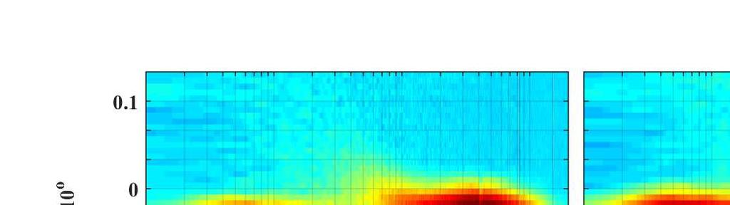
20 Fig.. Normalised velocity PSD for NACA 65(1)-1 airfoil at location x = c. 19 of 1
21 IV. Conclusions Experimental study on NACA 1 and NACA 65(1)-1 attached with serrated trailing edges have been carried out to better understand their aerodynamic and aeroacoustic performance. The experimental results show that the trailing edge serration can change the aerodynamic performances significantly. The level of performance change depends on the type of airfoil and the geometrical characteristics of the serration. Eventhough the C L α curve trend is not affected by the serrations the lift coefficient is affected and the post stall characteristics of the airfoil is changed. The flow field results show that the serrations significantly affect the velocity dip location and velocity deficit compared to the. The velocity profiles vary notably between the tip and root profiles that would cause significant shear stress between the tip and root planes. The velocity dip location shows an upward shift in the wake profiles at the root positions relative to the baseline and the tip positions. This indicates that the flow originating from the pressure surface passes through the airfoil root through the serration valleys moving upwards like a jet flow. The wake turning (downwash) angle for the root positions are significantly lesser than that of the and tip positions. This shows the flow field over the serration is predominantly three dimensional with strong vortices present in the spanwise and streamwise direction. This three dimensional flow and vortices influences the turbulent energy decay at the wake region bring down the turbulence level significantly compared to the baseline at about x =.5c. This is very important when considering noise generated from fan flow interaction with OGV since the inlet turbulence plays a major role in airfoil self noise. Moreover since the fan blades are operated at high angles of attack the reduction in inlet turbulence will aid delay the flow separation. Wake energy content results showed that at small or moderate pre-stall angles of attack leads to an increase of energy above the chord-line and decrease below the chord-line, while that reverses at post-stall angles. Acknowledgments The technical support and advice provided by Dr. Raf Theunissen for experimental setup is gratefully acknowledged. M.A. would like to acknowledged the financial support provided by the Royal Academy of Engineering. References [1] Hardin, J. C., Airframe self-nosie - four years researchitle, NASA Tech Memo, [] Brooks, T., Pope, D., and Marcolini, M., self-noise and prediction, NASA Reference Publication 118, 1989, pp. 14. [3] Williams, J. E. F. and Hall, L. H., Aerodynamic sound generation by turbulent flow in the vicinity of a scattering half plane, Journal of Fluid Mechanics, Vol. 4, 197, pp [4] Howe, M. S., Noise produced by a sawtooth trailing edge, The Journal of the Acoustical Society of America, Vol. 9, No. 1, 1991, pp. 48. [5] Gruber, M., Azarpeyvand, M., and Joseph, P., trailing edge noise reduction by the introduction of sawtooth and slitted trailing edge geometries, Proceedings of th International Congress on Acoustics, 1, pp [6] Jones, L. and Sandberg, R., Numerical Investigation of Self-Noise Reduction by Addition of Trailing-Edge Serrations, 16th AIAA/CEAS Aeroacoustics Conference, 1, pp [7] Fernandes, G. C., Weinmann, M., and Sandberg, R. D., Applicability of RANS models for accurate computation of flow over airfoils with serrated trailing edges, 5th European Conference on Computational Fluid Dynamics, ECCOMAS CFD 1, 1, pp [8] Sandberg, R. D. and Jones, L. E., Direct numerical simulations of low Reynolds number flow over airfoils with trailing-edge serrations, Journal of Sound and Vibration, Vol. 33, No. 16, 11, pp [9] Jones, L. E. and Sandberg, R. D., Acoustic and hydrodynamic analysis of the flow around an aerofoil with trailing-edge serrations, Journal of Fluid Mechanics, Vol. 76, 1, pp [1] Moreau, D., Brooks, L., and Doolan, C., On the noise reduction mechanism of a flat plate serrated trailing edge at low-tomoderate Reynolds number, 18th AIAA/CEAS Aeroacoustics Conference (33rd AIAA Aeroacoustics Conference), 1, pp. 1. [11] Gruber, M., Aerofoil noise reduction by edge treatments, Doctoral thesis, University of Southampton, 1. [1] Gruber, M., Joseph, P. F., and Azarpeyvand, M., An experimental investigation of novel trailing edge geometries on airfoil trailing edge noise reduction, 19th AIAA/CEAS Aeroacoustics Conference, Berlin, Germany, 13, pp [13] Azarpeyvand, M., Gruber, M., and Joseph, P. F., An analytical investigation of trailing edge noise reduction using novel serrations, 19th AIAA/CEAS Aeroacoustics Conference, Berlin, Germany, 13, pp [14] Chong, T. P. and Joseph, P. F., An experimental study of airfoil instability tonal noise with trailing edge serrations, Journal of Sound and Vibration, Vol. 33, No. 4, 13, pp of 1
22 [15] Chong, T. P., Joseph, P. F., and Gruber, M., self noise reduction by non-flat plate type trailing edge serrations, Applied Acoustics, Vol. 74, No. 4, 13, pp [16] Liang, J., Weiyang, Q., Liangfeng, W., Fan, T., and Weijie, C., Experimental and Numerical Study on Noise Reduction Mechanisms of an with Serrated trailing edge, th AIAA/CEAS Aeroacoustics Conference, Atlanta, GA, 14, pp [17] Sanjosé, M., Méon, C., Masson, V., and Moreau, S., Direct numerical simulation of acoustic reduction using serrated trailingedge on an isolated airfoil, th AIAA/CEAS Aeroacoustics Conference, Atlanta, GA, 14, pp [18] Lau, A. S. H., Haeri, S., and Kim, J. W., The effect of wavy leading edges on aerofoil-gust interaction noise, Journal of Sound and Vibration, Vol. 33, No. 4, 13, pp [19] Liu, X., Azarpeyvand, M., and Theunissen, R., On the Aerodynamic Performance of Serrated s, nd International Congress on Sound and Vibration, Florence, italy, 15, pp [] Liu, X., Kamliya Jawahar, H., Azarpeyvand, M., and Theunissen, R., Aerodynamic and Aeroacoustic Performance of Serrated s, 1st AIAA/CEAS Aeroacoustics Conference, Dallas, TX, 15, pp [1] Chong, T. P. and Vathylakis, A., On the aeroacoustic and flow structures developed on a flat plate with a serrated sawtooth trailing edge, Journal of Sound and Vibration, Vol. 354, 15, pp [] Avallone, F., Arce Leon, C., Pröbsting, S., Lynch, K., and Ragni, D., Tomographic-PIV investigation of the flow over serrated trailing-edges, AIAA SciTech/ 54th AIAA Aerospace Sciences Meeting, San Diego, California, 16, pp [3] Lyu, B., Azarpeyvand, M., and Sinayoko, S., Prediction of noise from serrated trailing-edges, Journal of Fluid Mechanics, Vol. 793, 16, pp [4] Vathylakis, A., Chong, T. P., and Joseph, P. F., Poro-Serrated Trailing-Edge Devices for Self-Noise Reduction, AIAA Journal, Vol. 53, No. 11, 15, pp [5] Herr, M. and Dobrzynski, W., Experimental Investigations in Low-Noise Trailing-Edge Design, AIAA Journal, Vol. 46, No. 6, 5, pp [6] Finez, A., Jondeau, E., Roger, M., and Jacob, M. C., Broadband noise reduction with trailing edge brushes, Proceedings of the 16th AIAA/CEAS aeroacoustics conference, 1, pp [7] Oerlemans, S., Fisher, M., Maeder, T., and Kögler, K., Reduction of wind turbine noise using optimized airfoils and trailingedge serrations, AIAA Journal, Vol. 47, No. 6, 9, pp [8] Boutilier, M. S. H., Experimental Investigation of Transition over a NACA 18 at a Low Reynolds Number, Master of applied science, University of Waterloo, 11. [9] Theunissen, R., Di Sante, a., Riethmuller, M. L., and Van Den Braembussche, R. a., Confidence estimation using dependent circular block bootstrapping: Application to the statistical analysis of PIV measurements, Experiments in Fluids, Vol. 44, No. 4, 8, pp of 1
University of Bristol - Explore Bristol Research. Publisher's PDF, also known as Version of record
 Liu, X., Azarpeyvand, M., & Joseph, P. (2015). On the acoustic and aerodynamic performance of serrated airfoils. Paper presented at The 22nd International Congress on Sound and Vibration, Florence, France.
A comparison of NACA 0012 and NACA 0021 self-noise at low Reynolds number
 A comparison of NACA 12 and NACA 21 self-noise at low Reynolds number A. Laratro, M. Arjomandi, B. Cazzolato, R. Kelso Abstract The self-noise of NACA 12 and NACA 21 airfoils are recorded at a Reynolds
Keywords: dynamic stall, free stream turbulence, pitching airfoil
 Applied Mechanics and Materials Vol. 225 (2012) pp 103-108 Online available since 2012/Nov/29 at www.scientific.net (2012) Trans Tech Publications, Switzerland doi:10.4028/www.scientific.net/amm.225.103
Trailing edge noise production, prediction and control
 Trailing edge noise production, prediction and control Con Doolan, Danielle Moreau, Elias Arcondoulis and Cristobal Albarracin School of Mechanical Engineering, University of Adelaide, South Australia,
Wind tunnel effects on wingtip vortices
 48th AIAA Aerospace Sciences Meeting Including the New Horizons Forum and Aerospace Exposition 4-7 January 2010, Orlando, Florida AIAA 2010-325 Wind tunnel effects on wingtip vortices Xin Huang 1, Hirofumi
EXPERIMENTAL ANALYSIS OF THE CONFLUENT BOUNDARY LAYER BETWEEN A FLAP AND A MAIN ELEMENT WITH SAW-TOOTHED TRAILING EDGE
 24 TH INTERNATIONAL CONGRESS OF THE AERONAUTICAL SCIENCES EXPERIMENTAL ANALYSIS OF THE CONFLUENT BOUNDARY LAYER BETWEEN A FLAP AND A MAIN ELEMENT WITH SAW-TOOTHED TRAILING EDGE Lemes, Rodrigo Cristian,
Tim Lee s journal publications
 Tim Lee s journal publications 82. Lee, T., and Tremblay-Dionne, V., (2018) Impact of wavelength and amplitude of a wavy ground on a static NACA 0012 airfoil submitted to Journal of Aircraft (paper in
Experimental and Theoretical Investigation for the Improvement of the Aerodynamic Characteristic of NACA 0012 airfoil
 International Journal of Mining, Metallurgy & Mechanical Engineering (IJMMME) Volume 2, Issue 1 (214) ISSN 232 46 (Online) Experimental and Theoretical Investigation for the Improvement of the Aerodynamic
AERODYNAMIC CHARACTERISTICS OF SPIN PHENOMENON FOR DELTA WING
 ICAS 2002 CONGRESS AERODYNAMIC CHARACTERISTICS OF SPIN PHENOMENON FOR DELTA WING Yoshiaki NAKAMURA (nakamura@nuae.nagoya-u.ac.jp) Takafumi YAMADA (yamada@nuae.nagoya-u.ac.jp) Department of Aerospace Engineering,
 et al. [25], Noack et al. [26] for circular cylinder flows, Van Oudheusden [27] for square cylinder and Durgesh [28] for a flat plate model. The first two modes appear as phase-shifted versions of each
EXPERIMENTAL ANALYSIS OF FLOW OVER SYMMETRICAL AEROFOIL Mayank Pawar 1, Zankhan Sonara 2 1,2
 EXPERIMENTAL ANALYSIS OF FLOW OVER SYMMETRICAL AEROFOIL Mayank Pawar 1, Zankhan Sonara 2 1,2 Assistant Professor,Chandubhai S. Patel Institute of Technology, CHARUSAT, Changa, Gujarat, India Abstract The
The Effect of Blade Thickness and Angle of Attack on Broadband Fan Noise
 The Effect of Blade Thickness and Angle of Attack on Broadband Fan Noise Stewart Glegg Florida Atlantic University and William Devenport Virginia Tech Work Supported by ONR, Prog. Manager: Dr. Ron Joslin
Influence of rounding corners on unsteady flow and heat transfer around a square cylinder
 Influence of rounding corners on unsteady flow and heat transfer around a square cylinder S. K. Singh Deptt. of Mech. Engg., M. B. M. Engg. College / J. N. V. University, Jodhpur, Rajasthan, India Abstract
Unsteady airfoil experiments
 Unsteady airfoil experiments M.F. Platzer & K.D. Jones AeroHydro Research & Technology Associates, Pebble Beach, CA, USA. Abstract This paper describes experiments that elucidate the dynamic stall phenomenon
NAWEA 2015 SYMPOSIUM
 Aerodynamics and Aeroacoustics of Spanwise Wavy Trailing Edge Flatback Airfoils: Design Improvement Seung Joon Yang James D. Baeder Alfred Gessow Rotorcraft Center Department of Aerospace Engineering,
Numerical Simulation And Aerodynamic Performance Comparison Between Seagull Aerofoil and NACA 4412 Aerofoil under Low-Reynolds 1
 Advances in Natural Science Vol. 3, No. 2, 2010, pp. 244-20 www.cscanada.net ISSN 171-7862 [PRINT] ISSN 171-7870 [ONLINE] www.cscanada.org *The 3rd International Conference of Bionic Engineering* Numerical
JOURNAL PUBLICATIONS
 1 JOURNAL PUBLICATIONS 71. Lee, T., Mageed, A., Siddiqui, B. and Ko, L.S., (2016) Impact of ground proximity on aerodynamic properties of an unsteady NACA 0012 airfoil, submitted to Journal of Aerospace
J. Szantyr Lecture No. 21 Aerodynamics of the lifting foils Lifting foils are important parts of many products of contemporary technology.
 J. Szantyr Lecture No. 21 Aerodynamics of the lifting foils Lifting foils are important parts of many products of contemporary technology. < Helicopters Aircraft Gliders Sails > < Keels and rudders Hydrofoils
AE Dept., KFUPM. Dr. Abdullah M. Al-Garni. Fuel Economy. Emissions Maximum Speed Acceleration Directional Stability Stability.
 Aerodynamics: Introduction Aerodynamics deals with the motion of objects in air. These objects can be airplanes, missiles or road vehicles. The Table below summarizes the aspects of vehicle performance
The Effect of Gurney Flap Height on Vortex Shedding Modes Behind Symmetric Airfoils
 The Effect of Gurney Flap Height on Vortex Shedding Modes Behind Symmetric Airfoils Daniel R. Troolin 1, Ellen K. Longmire 2, Wing T. Lai 3 1: TSI Incorporated, St. Paul, USA, dan.troolin@tsi.com 2: University
ANALYSIS OF AERODYNAMIC CHARACTERISTICS OF A SUPERCRITICAL AIRFOIL FOR LOW SPEED AIRCRAFT
 ANALYSIS OF AERODYNAMIC CHARACTERISTICS OF A SUPERCRITICAL AIRFOIL FOR LOW SPEED AIRCRAFT P.Sethunathan 1, M.Niventhran 2, V.Siva 2, R.Sadhan Kumar 2 1 Asst.Professor, Department of Aeronautical Engineering,
Analyses of the mechanisms of amplitude modulation of aero-acoustic wind turbine sound
 Analyses of the mechanisms of amplitude modulation of aero-acoustic wind turbine sound Andreas Fischer Helge Aagaard Madsen Knud Abildgaard Kragh Franck Bertagnolio DTU Wind Energy Technical University
CFD AND EXPERIMENTAL STUDY OF AERODYNAMIC DEGRADATION OF ICED AIRFOILS
 Colloquium FLUID DYNAMICS 2008 Institute of Thermomechanics AS CR, v.v.i., Prague, October 22-24, 2008 p.1 CFD AND EXPERIMENTAL STUDY OF AERODYNAMIC DEGRADATION OF ICED AIRFOILS Vladimír Horák 1, Dalibor
STUDIES ON THE OPTIMUM PERFORMANCE OF TAPERED VORTEX FLAPS
 ICAS 2000 CONGRESS STUDIES ON THE OPTIMUM PERFORMANCE OF TAPERED VORTEX FLAPS Kenichi RINOIE Department of Aeronautics and Astronautics, University of Tokyo, Tokyo, 113-8656, JAPAN Keywords: vortex flap,
Numerical Investigation of Multi Airfoil Effect on Performance Increase of Wind Turbine
 International Journal of Engineering & Applied Sciences (IJEAS) International Journal of Engineering Applied Sciences (IJEAS) Vol.9, Issue 3 (2017) 75-86 Vol.x, Issue x(201x)x-xx http://dx.doi.org/10.24107/ijeas.332075
Numerical and Experimental Investigation of the Possibility of Forming the Wake Flow of Large Ships by Using the Vortex Generators
 Second International Symposium on Marine Propulsors smp 11, Hamburg, Germany, June 2011 Numerical and Experimental Investigation of the Possibility of Forming the Wake Flow of Large Ships by Using the
AERODYNAMIC CHARACTERISTICS OF NACA 0012 AIRFOIL SECTION AT DIFFERENT ANGLES OF ATTACK
 AERODYNAMIC CHARACTERISTICS OF NACA 0012 AIRFOIL SECTION AT DIFFERENT ANGLES OF ATTACK SUPREETH NARASIMHAMURTHY GRADUATE STUDENT 1327291 Table of Contents 1) Introduction...1 2) Methodology.3 3) Results...5
INVESTIGATION OF PRESSURE CONTOURS AND VELOCITY VECTORS OF NACA 0015IN COMPARISON WITH OPTIMIZED NACA 0015 USING GURNEY FLAP
 INVESTIGATION OF PRESSURE CONTOURS AND VELOCITY VECTORS OF NACA 0015IN COMPARISON WITH OPTIMIZED NACA 0015 USING GURNEY FLAP 1 ANANTH S SHARMA, 2 SUDHAKAR S, 3 SWATHIJAYAKUMAR, 4 B S ANIL KUMAR 1,2,3,4
PRESSURE DISTRIBUTION OF SMALL WIND TURBINE BLADE WITH WINGLETS ON ROTATING CONDITION USING WIND TUNNEL
 International Journal of Mechanical and Production Engineering Research and Development (IJMPERD ) ISSN 2249-6890 Vol.2, Issue 2 June 2012 1-10 TJPRC Pvt. Ltd., PRESSURE DISTRIBUTION OF SMALL WIND TURBINE
THE BRIDGE COLLAPSED IN NOVEMBER 1940 AFTER 4 MONTHS OF ITS OPENING TO TRAFFIC!
 OUTLINE TACOMA NARROWS BRIDGE FLOW REGIME PAST A CYLINDER VORTEX SHEDDING MODES OF VORTEX SHEDDING PARALLEL & OBLIQUE FLOW PAST A SPHERE AND A CUBE SUMMARY TACOMA NARROWS BRIDGE, USA THE BRIDGE COLLAPSED
APPLICATION OF RESEARCH RESULTS AT LM WIND POWER
 APPLICATION OF RESEARCH RESULTS AT LM WIND POWER Herning / March 27 / 2014 By Jesper Madsen Chief Engineer Aerodynamics and Acoustics AGENDA 1. EUDP Projects 1. DANAERO MW 2. Optimization of vortex generators
The effect of back spin on a table tennis ball moving in a viscous fluid.
 How can planes fly? The phenomenon of lift can be produced in an ideal (non-viscous) fluid by the addition of a free vortex (circulation) around a cylinder in a rectilinear flow stream. This is known as
Computational Analysis of Cavity Effect over Aircraft Wing
 World Engineering & Applied Sciences Journal 8 (): 104-110, 017 ISSN 079-04 IDOSI Publications, 017 DOI: 10.589/idosi.weasj.017.104.110 Computational Analysis of Cavity Effect over Aircraft Wing 1 P. Booma
GEOMETRY TIP CAP EFFECTS ON FORMATION AND NEAR WAKE EVOLUTION OF THE ROTOR TIP VORTICES
 36th AIAA Fluid Dynamics Conference and Exhibit 5-8 June 2006, San Francisco, California AIAA 2006-3376 GEOMETRY TIP CAP EFFECTS ON FORMATION AND NEAR WAKE EVOLUTION OF THE ROTOR TIP VORTICES Roxana Vasilescu
Citation Journal of Thermal Science, 18(4),
,") NAOSITE: Nagasaki University's Ac Title Author(s) Noise characteristics of centrifuga diffuser (Noise reduction by means leading tip) Murakami, Tengen; Ishida, Masahiro; Citation Journal of Thermal Science,
NAOSITE: Nagasaki University's Ac Title Author(s) Noise characteristics of centrifuga diffuser (Noise reduction by means leading tip) Murakami, Tengen; Ishida, Masahiro; Citation Journal of Thermal Science,
Aerodynamic Analysis of Blended Winglet for Low Speed Aircraft
 , July 1-3, 2015, London, U.K. Aerodynamic Analysis of Blended Winglet for Low Speed Aircraft Pooja Pragati, Sudarsan Baskar Abstract This paper provides a practical design of a new concept of massive
Aeroacoustic and Aerodynamic Performances of an Aerofoil Subjected to Sinusoidal Leading Edges
 Aeroacoustic and Aerodynamic Performances of an Aerofoil Subjected to Sinusoidal Leading Edges Tze Pei Chong 1, Alexandros Vathylakis 2, Archie McEwen 3, Foster Kemsley 4, Chioma Muhammad 5 and Saarim
ASME International Mechanical Engineering Congress & Exhibition IMECE 2013 November 15-21, 2013, San Diego, California, USA
 ASME International Mechanical Engineering Congress & Exhibition IMECE 2013 November 15-21, 2013, San Diego, California, USA IMECE2013-62734 AERODYNAMIC CHARACTERISTICS OF HORIZONTAL AXIS WIND TURBINE WITH
AN EXPERIMENTAL STUDY OF THE EFFECTS OF SWEPT ANGLE ON THE BOUNDARY LAYER OF THE 2D WING
 AN EXPERIMENTAL STUDY OF THE EFFECTS OF SWEPT ANGLE ON THE BOUNDARY LAYER OF THE 2D WING A. Davari *, M.R. Soltani, A.Tabrizian, M.Masdari * Assistant Professor, Department of mechanics and Aerospace Engineering,
Reduction of Skin Friction Drag in Wings by Employing Riblets
 Reduction of Skin Friction Drag in Wings by Employing Riblets Kousik Kumaar. R 1 Assistant Professor Department of Aeronautical Engineering Nehru Institute of Engineering and Technology Coimbatore, India
Experimental Investigation of End Plate Effects on the Vertical Axis Wind Turbine Airfoil Blade
 Experimental Investigation of End Plate Effects on the Vertical Axis Wind Turbine Airfoil Blade Rikhi Ramkissoon 1, Krishpersad Manohar 2 Ph.D. Candidate, Department of Mechanical and Manufacturing Engineering,
Aerodynamic Performance Optimization Of Wind Turbine Blade By Using High Lifting Device
 Aerodynamic Performance Optimization Of Wind Turbine Blade By Using High Lifting Device Razeen Ridhwan, Mohamed Alshaleeh, Arunvinthan S Abstract: In the Aerodynamic performance of wind turbine blade by
NUMERICAL INVESTIGATION FOR THE ENHANCEMENT OF THE AERODYNAMIC CHARACTERISTICS OF AN AEROFOIL BY USING A GURNEY FLAP
 Geotec., Const. Mat. & Env., ISSN:2186-2990, Japan, DOI: http://dx.doi.org/10.21660/2017.34.2650 NUMERICAL INVESTIGATION FOR THE ENHANCEMENT OF THE AERODYNAMIC CHARACTERISTICS OF AN AEROFOIL BY USING A
The Influence of Battle Damage on the Aerodynamic Characteristics of a Model of an Aircraft
 Proceedings of the 26 WSEAS/IASME International Conference on Fluid Mechanics, Miami, Florida, USA, January 18-2, 26 (pp7-76) The Influence of Battle on the Aerodynamic Characteristics of a Model of an
Energy from wind and water extracted by Horizontal Axis Turbine
 Energy from wind and water extracted by Horizontal Axis Turbine Wind turbines in complex terrain (NREL) Instream MHK turbines in complex bathymetry (VP East channel NewYork) Common features? 1) horizontal
Aerodynamic Analysis of a Symmetric Aerofoil
 214 IJEDR Volume 2, Issue 4 ISSN: 2321-9939 Aerodynamic Analysis of a Symmetric Aerofoil Narayan U Rathod Department of Mechanical Engineering, BMS college of Engineering, Bangalore, India Abstract - The
Results and Discussion for Steady Measurements
 Chapter 5 Results and Discussion for Steady Measurements 5.1 Steady Skin-Friction Measurements 5.1.1 Data Acquisition and Reduction A Labview software program was developed for the acquisition of the steady
Pressure distribution of rotating small wind turbine blades with winglet using wind tunnel
 Journal of Scientific SARAVANAN & Industrial et al: Research PRESSURE DISTRIBUTION OF SMALL WIND TURBINE BLADES WITH WINGLET Vol. 71, June 01, pp. 45-49 45 Pressure distribution of rotating small wind
Dynamic Stall For A Vertical Axis Wind Turbine In A Two-Dimensional Study
 Abstracts of Conference Papers: TSBE EngD Conference, TSBE Centre, University of Reading, Whiteknights, RG6 Dynamic Stall For A Vertical Axis Wind Turbine In A Two-Dimensional Study R. Nobile 1,*, Dr M.
THE EFFECT OF LEADING AND TRAILING EDGE PROTUBERANCES ON AEROFOIL PERFORMANCE
 HEFAT214 1 th International Conference on Heat Transfer, Fluid Mechanics and Thermodynamics 14 16 July 214 Orlando, Florida THE EFFECT OF LEADING AND TRAILING EDGE PROTUBERANCES ON AEROFOIL PERFORMANCE
COMPUTATIONAL FLOW MODEL OF WESTFALL'S LEADING TAB FLOW CONDITIONER AGM-09-R-08 Rev. B. By Kimbal A. Hall, PE
 COMPUTATIONAL FLOW MODEL OF WESTFALL'S LEADING TAB FLOW CONDITIONER AGM-09-R-08 Rev. B By Kimbal A. Hall, PE Submitted to: WESTFALL MANUFACTURING COMPANY September 2009 ALDEN RESEARCH LABORATORY, INC.
Design & Analysis of Natural Laminar Flow Supercritical Aerofoil for Increasing L/D Ratio Using Gurney Flap
 Design & Analysis of Natural Laminar Flow Supercritical Aerofoil for Increasing L/D Ratio Using Gurney Flap U.Praveenkumar 1, E.T.Chullai 2 M.Tech Student, School of Aeronautical Science, Hindustan University,
This is the author s final accepted version.
 Ibrahim, I.H., Joy, J. and New, T.N. (2016) Numerical Investigation on Flow Separation Control of Low Reynolds Number Sinusoidal Aerofoils. In: 46th AIAA Fluid Dynamics Conference, AIAA AVIATION Forum,
CFD Analysis ofwind Turbine Airfoil at Various Angles of Attack
 IOSR Journal of Mechanical and Civil Engineering (IOSR-JMCE) e-issn: 2278-1684,p-ISSN: 2320-334X, Volume 13, Issue 4 Ver. II (Jul. - Aug. 2016), PP 18-24 www.iosrjournals.org CFD Analysis ofwind Turbine
Experimental Investigation on the Ice Accretion Effects of Airplane Compressor Cascade of Stator Blades on the Aerodynamic Coefficients
 Journal of Applied Fluid Mechanics, Vol. 6, No. 2, pp. 6775, 23. Available online at www.jafmonline.net, ISSN 735-3572, EISSN 735-3645. Experimental Investigation on the Ice Accretion Effects of Airplane
Lecture # 08: Boundary Layer Flows and Drag
 AerE 311L & AerE343L Lecture Notes Lecture # 8: Boundary Layer Flows and Drag Dr. Hui H Hu Department of Aerospace Engineering Iowa State University Ames, Iowa 511, U.S.A y AerE343L #4: Hot wire measurements
AN EXPERIMENTAL AND COMPUTATIONAL STUDY OF THE AERODYNAMIC CHARACTERISTICS AN OSCILLATORY PITCHING NACA0012 AEROFOIL
 AN EXPERIMENTAL AND COMPUTATIONAL STUDY OF THE AERODYNAMIC CHARACTERISTICS AN OSCILLATORY PITCHING NACA0012 AEROFOIL Ashim Yadav, Simon Prince & Jenny Holt School of Aerospace, Transport and Manufacturing,
High fidelity gust simulations around a transonic airfoil
 High fidelity gust simulations around a transonic airfoil AEROGUST Workshop 27 th - 28 th April 2017, University of Liverpool Presented by B. Tartinville (Numeca) Outline of the presentation 1Objectives
Low Speed Wind Tunnel Wing Performance
 Low Speed Wind Tunnel Wing Performance ARO 101L Introduction to Aeronautics Section 01 Group 13 20 November 2015 Aerospace Engineering Department California Polytechnic University, Pomona Team Leader:
Aerodynamic characteristics around the stalling angle of the discus using a PIV
 10TH INTERNATIONAL SYMPOSIUM ON PARTICLE IMAGE VELOCIMETRY PIV13 Delft, The Netherlands, July 1-3, 2013 Aerodynamic characteristics around the stalling angle of the discus using a PIV Kazuya Seo 1 1 Department
Experimental investigation on the aft-element flapping of a two-element airfoil at high attack angle
 Experimental investigation on the aft-element flapping of a two-element airfoil at high attack angle Tan Guang-kun *, Shen Gong-xin, Su Wen-han Beijing University of Aeronautics and Astronautics (BUAA),
Unsteady Aerodynamics of Tandem Airfoils Pitching in Phase
 Unsteady Aerodynamics of Tandem Airfoils Pitching in Phase Ravindra A Shirsath and Rinku Mukherjee Abstract This paper presents the results of a numerical simulation of unsteady, incompressible and viscous
Influence of wing span on the aerodynamics of wings in ground effect
 Influence of wing span on the aerodynamics of wings in ground effect Sammy Diasinos 1, Tracie J Barber 2 and Graham Doig 2 Abstract A computational fluid dynamics study of the influence of wing span has
WESEP 594 Research Seminar
 WESEP 594 Research Seminar Aaron J Rosenberg Department of Aerospace Engineering Iowa State University Major: WESEP Co-major: Aerospace Engineering Motivation Increase Wind Energy Capture Betz limit: 59.3%
CFD Study of Solid Wind Tunnel Wall Effects on Wing Characteristics
 Indian Journal of Science and Technology, Vol 9(45), DOI :10.17485/ijst/2016/v9i45/104585, December 2016 ISSN (Print) : 0974-6846 ISSN (Online) : 0974-5645 CFD Study of Solid Wind Tunnel Wall Effects on
CIRCULATION CONTROLLED AIRFOIL ANALYSIS THROUGH 360 DEGREES ANGLE OF ATTACK
 Proceedings of the ASME 2009 3rd International Conference of Proceedings Energy Sustainability of ES2009 Energy Sustainability ES2009 July July 19-23, 2009, 2009, San San Francisco, California, USA ES2009-90341
Lecture # 08: Boundary Layer Flows and Controls
 AerE 344 Lecture Notes Lecture # 8: Boundary Layer Flows and Controls Dr. Hui Hu Department of Aerospace Engineering Iowa State University Ames, Iowa 511, U.S.A Flow Separation on an Airfoil Quantification
Quantification of the Effects of Turbulence in Wind on the Flutter Stability of Suspension Bridges
 Quantification of the Effects of Turbulence in Wind on the Flutter Stability of Suspension Bridges T. Abbas 1 and G. Morgenthal 2 1 PhD candidate, Graduate College 1462, Department of Civil Engineering,
PERFORMANCE OF A FLAPPED DUCT EXHAUSTING INTO A COMPRESSIBLE EXTERNAL FLOW
 24 TH INTERNATIONAL CONGRESS OF THE AERONAUTICAL SCIENCES PERFORMANCE OF A FLAPPED DUCT EXHAUSTING INTO A COMPRESSIBLE EXTERNAL FLOW P. R. Pratt, J. K. Watterson, E. Benard, S. Hall School of Aeronautical
Effect of Co-Flow Jet over an Airfoil: Numerical Approach
 Contemporary Engineering Sciences, Vol. 7, 2014, no. 17, 845-851 HIKARI Ltd, www.m-hikari.com http://dx.doi.org/10.12988/ces.2014.4655 Effect of Co-Flow Jet over an Airfoil: Numerical Approach Md. Riajun
INTERFERENCE EFFECT AND FLOW PATTERN OF FOUR BIPLANE CONFIGURATIONS USING NACA 0024 PROFILE
 Proceedings of the International Conference on Mechanical Engineering 211 (ICME211) 18-2 December 211, Dhaka, Bangladesh ICME11-FL-1 INTERFERENCE EFFECT AND FLOW PATTERN OF FOUR BIPLANE CONFIGURATIONS
HEFAT th International Conference on Heat Transfer, Fluid Mechanics and Thermodynamics July 2012 Malta
 HEFAT212 9 th International Conference on Heat Transfer, Fluid Mechanics and Thermodynamics 16 18 July 212 Malta AN EXPERIMENTAL STUDY OF SWEEP ANGLE EFFECTS ON THE TRANSITION POINT ON A 2D WING BY USING
High Swept-back Delta Wing Flow
 Advanced Materials Research Submitted: 2014-06-25 ISSN: 1662-8985, Vol. 1016, pp 377-382 Accepted: 2014-06-25 doi:10.4028/www.scientific.net/amr.1016.377 Online: 2014-08-28 2014 Trans Tech Publications,
Measurement and simulation of the flow field around a triangular lattice meteorological mast
 Measurement and simulation of the flow field around a triangular lattice meteorological mast Matthew Stickland 1, Thomas Scanlon 1, Sylvie Fabre 1, Andrew Oldroyd 2 and Detlef Kindler 3 1. Department of
EFFECT OF GURNEY FLAPS AND WINGLETS ON THE PERFORMANCE OF THE HAWT
 Chapter-6 EFFECT OF GURNEY FLAPS AND WINGLETS ON THE PERFORMANCE OF THE HAWT 6.1 Introduction The gurney flap (wicker bill) was a small flat tab projecting from the trailing edge of a wing. Typically it
An Impeller Blade Analysis of Centrifugal Gas Compressor Using CFD
 An Impeller Blade Analysis of Centrifugal Gas Compressor Using CFD Vivek V. Kulkarni Department of Mechanical Engineering KLS Gogte Institute of Technology, Belagavi, Karnataka Dr. Anil T.R. Department
Computational Analysis of Blunt Trailing Edge NACA 0012 Airfoil
 Computational Analysis of Blunt Trailing Edge NACA 2 Airfoil Anusha K Department of Aerospace Engineering Madras Institute of Technology, India anusugan7@gmail.com Abstract Blunt trailing edge airfoil
SEMI-SPAN TESTING IN WIND TUNNELS
 25 TH INTERNATIONAL CONGRESS OF THE AERONAUTICAL SCIENCES SEMI-SPAN TESTING IN WIND TUNNELS S. Eder, K. Hufnagel, C. Tropea Chair of Fluid Mechanics and Aerodynamics, Darmstadt University of Technology
Study on wind turbine arrangement for offshore wind farms
 Downloaded from orbit.dtu.dk on: Jul 01, 2018 Study on wind turbine arrangement for offshore wind farms Shen, Wen Zhong; Mikkelsen, Robert Flemming Published in: ICOWEOE-2011 Publication date: 2011 Document
Avai 193 Fall 2016 Laboratory Greensheet
 Avai 193 Fall 2016 Laboratory Greensheet Lab Report 1 Title: Instrumentation Test Technique Research Process: Break into groups of 4 people. These groups will be the same for all of the experiments performed
CIRCULATION PRODUCTION AND SHEDDING FROM VERTICAL AXIS WIND TURBINE BLADES UNDERGOING DYNAMIC STALL
 June 3 - July 3, 5 Melbourne, Australia 9 7D-3 CIRCULATION PRODUCTION AND SHEDDING FROM VERTICAL AXIS WIND TURBINE BLADES UNDERGOING DYNAMIC STALL Abel-John Buchner,,, Julio Soria,3, Alexander J. Smits,
Anna University Regional office Tirunelveli
 Effect of Tubercle Leading Edge Control Surface on the Performance of the Double Delta Wing Fighter Aircraft P Sharmila 1, S Rajakumar 2 1 P.G. Scholar, 2 Assistant Professor, Mechanical Department Anna
Incompressible Potential Flow. Panel Methods (3)
") Incompressible Potential Flow Panel Methods (3) Outline Some Potential Theory Derivation of the Integral Equation for the Potential Classic Panel Method Program PANEL Subsonic Airfoil Aerodynamics Issues
Incompressible Potential Flow Panel Methods (3) Outline Some Potential Theory Derivation of the Integral Equation for the Potential Classic Panel Method Program PANEL Subsonic Airfoil Aerodynamics Issues
COMPUTATIONAL FLUID DYNAMIC ANALYSIS OF AIRFOIL NACA0015
 International Journal of Mechanical Engineering and Technology (IJMET) Volume 8, Issue 2, February 2017, pp. 210 219 Article ID: IJMET_08_02_026 Available online at http://www.iaeme.com/ijmet/issues.asp?jtype=ijmet&vtype=8&itype=2
EXPERIMENTAL INVESTIGATION OF LIFT & DRAG PERFORMANCE OF NACA0012 WIND TURBINE AEROFOIL
 EXPERIMENTAL INVESTIGATION OF LIFT & DRAG PERFORMANCE OF NACA0012 WIND TURBINE AEROFOIL Mr. Sandesh K. Rasal 1, Mr. Rohan R. Katwate 2 1 PG Student, 2 Assistant Professor, DYPSOEA Ambi Talegaon, Heat Power
Inlet Swirl on Turbocharger Compressor Performance
 Inlet Swirl on Turbocharger Compressor Performance Lei Huang, Ying Liu, Hua Chen* National laboratory of Engine Turbocharging Technology, Tianjin, China *corresponding author: Tel.:+86-22-5870-7069; fax:
Effect of Flapping Frequency and Leading Edge Profile on Airfoil Leading Edge Vortical Structures
 Effect of Flapping Frequency and Leading Edge Profile on Airfoil Leading Edge Vortical Structures Wesley N. Fassmann Brigham Young University Scott L. Thomson Brigham Young University Abstract By varying
Asymmetric vortex shedding flow past an inclined flat plate at high incidence
 Title Asymmetric vortex shedding flow past an inclined flat plate at high incidence Author(s) Lam, KM; Leung, MYH Citation European Journal Of Mechanics, B/Fluids, 5, v. 4 n., p. - 48 Issued Date 5 URL
AERODYNAMICS I LECTURE 7 SELECTED TOPICS IN THE LOW-SPEED AERODYNAMICS
 LECTURE 7 SELECTED TOPICS IN THE LOW-SPEED AERODYNAMICS The sources of a graphical material used in this lecture are: [UA] D. McLean, Understanding Aerodynamics. Arguing from the Real Physics. Wiley, 2013.
L'evoluzione delle tecniche sperimentali nell'idrodinamica navale Particle Image Velocimetry, potenzialità, criticità ed applicazioni
 L'evoluzione delle tecniche sperimentali nell'idrodinamica navale Particle Image Velocimetry, potenzialità, criticità ed applicazioni Massimo Falchi, Mario Felli, Giovanni Aloisio, Silvano Grizzi, Fabio
CFD DESIGN STUDY OF A CIRCULATION CONTROL INLET GUIDE VANE OF AN AEROFOIL
 Int. J. Mech. Eng. & Rob. Res. 2012 Manjunath Ichchangi and Manjunath H, 2012 Research Paper ISSN 2278 0149 www.ijmerr.com Vol. 1, No. 3, October 2012 2012 IJMERR. All Rights Reserved CFD DESIGN STUDY
Investigations on axial compressor cascades with aspiration on blades and hub
 Investigations on axial compressor cascades with aspiration hub Thierry Obrecht Michel Dumas Elia Colombo - Cécile Deslot Snecma (Groupe Safran) Peter Ott Villaroche, France Laboratoire de Thermique Appliquée
Computational Investigation of Airfoils with Miniature Trailing Edge Control Surfaces
 AIAA-24-5 Computational Investigation of Airfoils with Miniature Trailing Edge Control Surfaces Hak-Tae Lee, Ilan M. Kroo Stanford University, Stanford, CA 9435 Abstract Miniature trailing edge effectors
Control of the Spanwise Distribution of Circulation on NACA 0012 and Flat Plate Wings
 45th AIAA Aerospace Sciences Meeting and Exhibit 8-11 January 2007, Reno, Nevada AIAA 2007-1121 Control of the Spanwise Distribution of Circulation on NACA 0012 and Flat Plate Wings D. Williams *, S. Doshi,
Investigation on 3-D Wing of commercial Aeroplane with Aerofoil NACA 2415 Using CFD Fluent
 Investigation on 3-D of commercial Aeroplane with Aerofoil NACA 2415 Using CFD Fluent Rohit Jain 1, Mr. Sandeep Jain 2, Mr. Lokesh Bajpai 3 1PG Student, 2 Associate Professor, 3 Professor & Head 1 2 3
DYAMIC BEHAVIOR OF VORTEX SHEDDING FROM AN OSCILLATING THREE-DIMENSIONAL AIRFOIL
 27 TH INTERNATIONAL CONGRESS OF THE AERONAUTICAL SCIENCES DYAMIC BEHAVIOR OF VORTEX SHEDDING FROM AN OSCILLATING THREE-DIMENSIONAL AIRFOIL Hiroaki Hasegawa*, Kennichi Nakagawa** *Department of Mechanical
Experimental Investigation Of Flow Past A Rough Surfaced Cylinder
 (AET- 29th March 214) RESEARCH ARTICLE OPEN ACCESS Experimental Investigation Of Flow Past A Rough Surfaced Cylinder Monalisa Mallick 1, A. Kumar 2 1 (Department of Civil Engineering, National Institute
NUMERICAL SIMULATION OF ACTIVE FLOW CONTROL BASED ON STREAMWISE VORTICES FOR A BLUNT TRAILING EDGE AIRFOIL
 BBAA VI International Colloquium on: Bluff Bodies Aerodynamics & Applications Milano, Italy, July, 20-24 2008 NUMERICAL SIMULATION OF ACTIVE FLOW CONTROL BASED ON STREAMWISE VORTICES FOR A BLUNT TRAILING
A COMPUTATIONAL STUDY ON THE DESIGN OF AIRFOILS FOR A FIXED WING MAV AND THE AERODYNAMIC CHARACTERISTIC OF THE VEHICLE
 28 TH INTERNATIONAL CONGRESS OF THE AERONAUTICAL SCIENCES A COMPUTATIONAL STUDY ON THE DESIGN OF AIRFOILS FOR A FIXED WING MAV AND THE AERODYNAMIC CHARACTERISTIC OF THE VEHICLE Jung-Hyun Kim*, Kyu-Hong
ROAD MAP... D-1: Aerodynamics of 3-D Wings D-2: Boundary Layer and Viscous Effects D-3: XFLR (Aerodynamics Analysis Tool)
") Unit D-1: Aerodynamics of 3-D Wings Page 1 of 5 AE301 Aerodynamics I UNIT D: Applied Aerodynamics ROAD MAP... D-1: Aerodynamics of 3-D Wings D-: Boundary Layer and Viscous Effects D-3: XFLR (Aerodynamics
Unit D-1: Aerodynamics of 3-D Wings Page 1 of 5 AE301 Aerodynamics I UNIT D: Applied Aerodynamics ROAD MAP... D-1: Aerodynamics of 3-D Wings D-: Boundary Layer and Viscous Effects D-3: XFLR (Aerodynamics