SHIP FORM DEFINITION The Shape of a Ship
|
|
|
- Alban Small
- 6 years ago
- Views:
Transcription
1 SHIP FORM DEFINITION The Shape of a Ship
2 The Traditional Way to Represent the Hull Form A ship's hull is a very complicated three dimensional shape. With few exceptions an equation cannot be written that fully describes the shape of a ship. Therefore, naval engineers have placed great emphasis on the graphical description of hull forms. Until very recently, most of this work was done by hand. Today high-speed digital computers assist the engineer with the drawings, but they are not substitutes for imagination and judgment. Traditionally, the ship's hull form is represented graphically by a lines drawing. The lines drawing consists of projections of the intersection of the hull with a series of planes. The planes are equally spaced in each of the three dimensions (x, y, z). Planes in one dimension will be perpendicular to planes in the other two dimensions. We say that the sets of planes are mutually perpendicular or orthogonal planes.
3 Lines Drawing- Lines Plan
4 The points of intersection of these planes with the hull results in a series of lines that are projected onto a single plane located on the front, top, or side of the ship. This results in three separate projections, or views, called the Half-Breadth Plan, Sheer plan and Body Plan. The creation of the linesplan from 3D ship hull form The projection of lines onto three orthogonal planes
5 To visualize how a lines drawing works, place the ship in an imaginary rectangular box whose sides just touch the keel (baseline) and sides of the ship. The bottom, side and front of the box will serve as the basis for three orthogonal projection screens on which lines will be projected onto. The lines to be projected result from the intersection of the hull with planes that are parallel to each of the three orthogonal planes mentioned.

6 The Half-Breadth Plan- Waterline Plan- TOP VIEW Think about our imaginary box. The bottom of the box is a reference plane called the base plane. The base plane is usually level with the keel. A series of planes parallel and above the base plane are imagined at regular intervals. Each plane will intersect the ship's hull and form a line at the points of intersection. These lines are called waterlines and are all projected onto a single plane called the Half Breadth Plan.

7 Creation of the half-breadth plan Each waterline shows the true shape of the hull from the top view for some elevation above the base plane which allows this line to serve as a pattern for the construction of the ship s framing.
8 The waterlines referred to here have nothing to do with where the ship actually floats. These waterlines are the intersection of the ship s hull with some imaginary plane above the base plane. There will be one plane above the base plane that coincides with the normal draft (draught) of the ship, this waterline is called the Design Water Line or Loaded Waterline. This waterline is actually the waterline the ship floats. The design water line is often represented on drawings as DWL, LWL or. Since ships are symmetric about their centerline they only need be drawn for the starboard or port side, thus the name of Half Breadth Plan


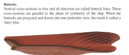
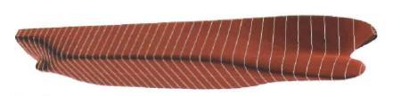
9 The Sheer Plan -Profile plan SIDE VIEW A plane that runs from bow to stern directly through the center of the ship and parallel to the sides of the imaginary box is called the centerline plane. A series of planes parallel to one side of the centerline plane are imagined at regular intervals from the centerline. Each plane will intersect the ship's hull and form a curved line at the points of intersection. These lines are called buttocks and are all projected onto a single plane called the Sheer Plan. Centerline plane stern bow

10 The creation of the sheer plan Sheer line of the ship Profile of the ship Each buttock line shows the true shape of the hull from the side view for some distance from the centerline of the ship. This allows them to serve as a pattern for the construction of the ship s longitudinal framing. The centerline plane shows a special buttock called the profile of the ship. The sheer plan gets its name from the idea of a sheer line on a ship. The sheer line on a ship is the upward longitudinal curve on ship s deck. It is the sheer line of the vessel which gives it a pleasing aesthetic quality.
11 The Body Plan - FRONT VIEW Port side Starboard Port side side Body plan Starboard side Planes parallel to the front and back of the imaginary box running port to starboard are called stations or sections. A ship is typically divided into 11, 21, 31, or 41 evenly spaced stations. The larger the ship the more stations will be made. An odd number of stations results in an even number of equal blocks between the stations. The body plan takes advantage of the ship's symmetry. Only half of each section is drawn because the other half is identical. By convention, the sections forward of amidships are drawn on the right side, and the sections aft of amidships are drawn on the left side. The amidships section is generally shown on both sides of the body plan. The vertical line in the center separating the left and right half of the ship is called the centerline.

12 Each section line shows the true shape of the hull from the front view for some longitudinal position on the ship which allows this line to serve as a pattern for the construction of the ship s transverse framing. Each station plane will intersect the ship's hull and form a curved line at the points of intersection. These lines are called sectional lines or sections and are all projected onto a single plane called the Body Plan
13 grid lines for buttocks grid lines for waterlines USNA Patrol Craft - Body Plan

14 design waterline DWL or LWL
15
16 Sections
17 aft or stern bow or stem The first forward station at the bow is usually labeled station number zero. This forward station is called the forward perpendicular (FP). By definition the FP is located at a longitudinal position as to intersect the stem of the ship at the DWL. The after-most station is called the after perpendicular (AP). By definition the AP is located at a longitudinal position as to intersect the stern at the DWL for ships with a transom stern or alternatively through the rudder stock of the vessel. The station midway between the perpendiculars is called the midships station, usually represented by the symbol. The length between these perpendiculars has the symbol Lpp. Engineers typically use the Lpp for calculations. There is also an overall ship length LOA that might be a more useful number to use if you were docking the ship.
18 Nowadays the lines plans are being made with the aid of computer programs that have the possibility to transform the shape of the vessel automatically when modifications in the ship s design require this. If the linesplan is ready, the programs may be used to calculate among other things the volume and displacement of the ship.
19
20 Hullform characteristics All aspects concerning the measurements of seagoing vessels are arranged in the certificate of registry act of Perpendiculars The forward and after perpendiculars shall be taken at the forward and after ends of the length (Lpp ). The forward perpendicular shall coincide with the foreside of the stem on the water line on which the length is measured. FP Fore perpendicular AP Aft perpendicular BL - Base line STERN PART STEM PART T a T T f BL AP FP
 The depth of a ship's keel below the waterline.")
21 Length between perpendiculars (L pp ) Distance between the fore and aft perpendicular Length over all (Loa) The horizontal distance from stem to stern Loaded waterline (Lwl) Horizontal distance between the stem and stern when the ship is on her summer mark. In other words the waterline of ship lying in the water. Draught (T) The depth of a ship's keel below the waterline. Trim The difference between the draught at the stem and stern Sheer STERN PART T a T T f STEM PART AP FP
 The vertical distance between the base line and upper deck.")
22 DWL BL Breadth (B) The maximum breadth of the ship as measured from the outer hull on starboard to port side Depth (D) The vertical distance between the base line and upper deck. The depth is measured at midships.
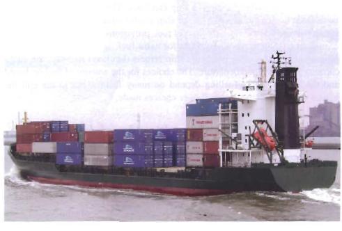
23 Camber Turn of bilge Rise of floor Sheer The upward rise of a ship s deck from amidships towards the bow and stern Camber The curving of the weather deck which ensures drainage Rise of floor Unique to some types of vessels like tugboats and fishing boats. This is the upwards rise of the lower edges of the floors from keel towards the bilges Turn of bilge Gives the radius of the bilge of the ship

24 Freeboard. The freeboard assigned is the distance measured vertically downwards amidships from the upper edge of the deck line to the upper edge of the related design waterline or loaded waterline. Call it a safety bulb!! Freeboard Deck. The freeboard deck is normally the uppermost complete deck exposed to weather and sea, which has permanent means of closing all openings in the weather part and below which all openings in the sides of the ship are fitted with permanent means of watertight closing. DWL
25 Freeboard Load line Safe loading, weight and balance have always been very serious issues for seafarers. In England, Samuel Plimsoll became the moving force to establish safe loading as a rule of law in Through his efforts, safe loading standards were adopted and forced by law. The first International Convention on Load Lines, adopted in 1930, was based on the principle of reserve buoyancy, although it was recognized then that the freeboard should also ensure adequate stability and avoid excessive stress on the ship's hull as a result of overloading. Load line conventions were conceived as instruments to assign the maximum safe draught for ships to operate at sea.
26 Freeboard Mark

27 The freeboard mark shall consist of a ring 300 mm in outside diameter and 25 mm wide which is intersected by a horizontal line 450 mm in length and 25 mm in breadth, the upper edge of which passes through the centre of the ring. The centre of the ring shall be placed amidships and at a distance equal to the assigned summer freeboard measured vertically below the upper edge of the deck line.
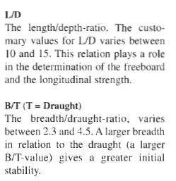
28 Proportions

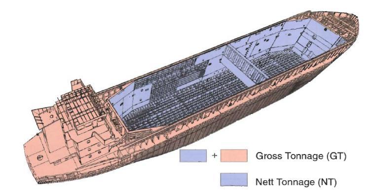
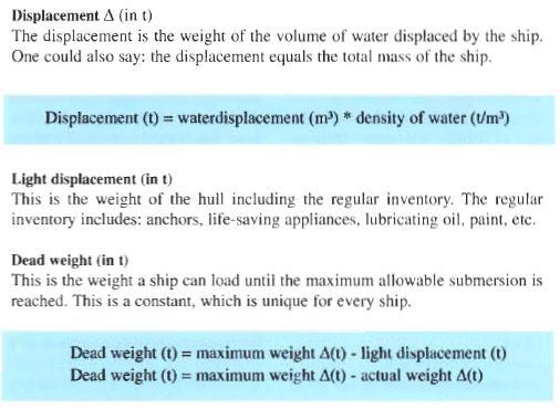
29 Volumes and weights
30
31


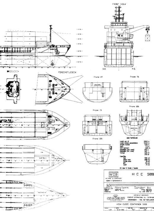
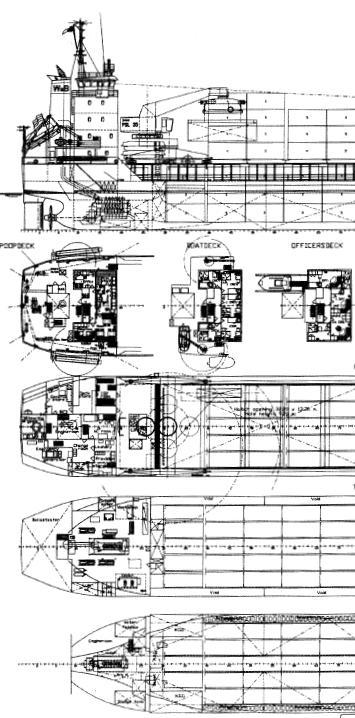
32 The cargo capacity determines the amount of money the ship makes

33 Ship Hull Form Coefficients
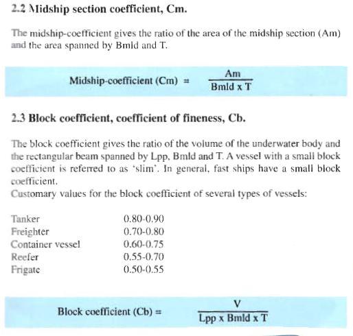
34

35 Graphical representation of block coefficient


36 A ship with a small block coefficient but a large midship section coefficient A ship with a large block coefficient but a large midship section coefficient

37 Prismatic coefficient Graphical representation of prismatic coefficient
38 Lets show a couple of lines plans that differ quite dramatically. The looker can tell from these lines plans that a ship would be slimmer with smaller coefficents and when the waterlines, section lines and buttocks are more closely spaced
39
40
41
42
43
44 DRAWINGS
45
46 Midship Section
47 Midship Section
positions of all parts (plate edges, stringers, frames and decks) from a")
48 Shell Expansion A shell expansion drawing may be created from any workshop design. The drawing shows the girth (measurement around the plates)positions of all parts (plate edges, stringers, frames and decks) from a specified datum position (usually, but not always, the baseline)
49

50 A typical shell expansion drawing
51 Other plans Construction plan Safety plan Docking plan Capacity plan
52
53
54
55
56
57
58
SECOND ENGINEER REG III/2 NAVAL ARCHITECTURE
 SECOND ENGINEER REG III/2 NAVAL ARCHITECTURE LIST OF TOPICS A B C D E F G H I J Hydrostatics Simpson's Rule Ship Stability Ship Resistance Admiralty Coefficients Fuel Consumption Ship Terminology Ship
S0300-A6-MAN-010 CHAPTER 2 STABILITY
 CHAPTER 2 STABILITY 2-1 INTRODUCTION This chapter discusses the stability of intact ships and how basic stability calculations are made. Definitions of the state of equilibrium and the quality of stability
Hydrostatics and Stability Dr. Hari V Warrior Department of Ocean Engineering and Naval Architecture Indian Institute of Technology, Kharagpur
 Hydrostatics and Stability Dr. Hari V Warrior Department of Ocean Engineering and Naval Architecture Indian Institute of Technology, Kharagpur Module No.# 01 Lecture No. # 01 Introduction Hello everybody.
COURSE OBJECTIVES CHAPTER 2
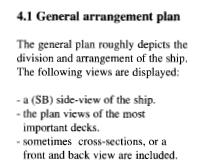
 COURSE OBJECTIVES CHAPTER 2 2. HULL FORM AND GEOMETRY 1. Be familiar with ship classifications 2. Explain the difference between aerostatic, hydrostatic, and hydrodynamic support 3. Be familiar with the
RULES PUBLICATION NO. 20/P SHIP SIDE STRENGTHENING OF FISHING VESSELS MOORING AT SEA ALONGSIDE OTHER VESSELS
 RULES PUBLICATION NO. 20/P SHIP SIDE STRENGTHENING OF FISHING VESSELS MOORING AT SEA ALONGSIDE OTHER VESSELS 1995 Publications P (Additional Rule Requirements), issued by Polski Rejestr Statków, complete
ANNEX 5 IMO MARINE CASULATY AND INCIDENT REPORT DAMAGE CARDS* AND INTACT STABILITY CASUALTY RECORDS
 ANNEX 5 IMO MARINE CASUATY AND INCIDENT REPORT DAMAGE CARDS* AND INTACT STABIITY CASUATY RECORDS Statistics of damaged ships and of intact stability casualties are important to the work of the Organization
Marine Kit 4 Marine Kit 4 Sail Smooth, Sail Safe
 Marine Kit 4 Marine Kit 4 Sail Smooth, Sail Safe Includes Basic ship Terminologies and Investigation Check list Index 1. Ship Terminology 03 2. Motions of a Floating Body...09 3. Ship Stability.10 4. Free
ITTC Recommended Procedures and Guidelines
 7.5- -- Page 1 of 6 Table of Contents 1 PURPOSE OF PROCEDURE 2 2 PARAMETERS...2 2.1 Definition of Variables...2 3 DESCRIPTION OF PROCEDURE...2 3.1...2 3.1.1 Hull Model...2 3.1.2 Propeller Model...3 3.1.3
1. For the purposes of this standard, the maximum weight capacity of a boat is:
 1. For the purposes of this standard, the maximum weight capacity of a boat is: a. The maximum load the boat may carry plus 32 divided by 141 b. The load displayed on the capacity label c. The load displayed
MSC Guidelines for the Submission of Stability Test (Deadweight Survey or Inclining Experiment) Results
 Results") S. E. HEMANN, CDR, Chief, Hull Division References a. 46 CFR 170, Subpart F Determination of Lightweight Displacement and Centers of Gravity b. NVIC 17-91 Guidelines for Conducting Stability Tests c. ASTM
S. E. HEMANN, CDR, Chief, Hull Division References a. 46 CFR 170, Subpart F Determination of Lightweight Displacement and Centers of Gravity b. NVIC 17-91 Guidelines for Conducting Stability Tests c. ASTM
OPERATIONS SEAFARER CERTIFICATION GUIDANCE NOTE SA MARITIME QUALIFICATIONS CODE
 Page 1 of 8 Compiled by Chief Examiner Approved by Qualifications Committee: 27 September 2013 OPERATIONS SEAFARER CERTIFICATION GUIDANCE NOTE SA MARITIME QUALIFICATIONS CODE Page 2 of 8 KNOWLEDGE, UNDERSTANDING
CERTIFICATES OF COMPETENCY IN THE MERCHANT NAVY MARINE ENGINEER OFFICER
 CERTIFICATES OF COMPETENCY IN THE MERCHANT NAVY MARINE ENGINEER OFFICER EXAMINATIONS ADMINISTERED BY THE SCOTTISH QUALIFICATIONS AUTHORITY ON BEHALF OF THE MARITIME AND COASTGUARD AGENCY STCW 95 CHIEF
Marine Construction & Welding Prof. Dr. N. R. Mandal Department of Ocean Engineering & Naval Architecture Indian Institute of Technology, Kharagpur
 Marine Construction & Welding Prof. Dr. N. R. Mandal Department of Ocean Engineering & Naval Architecture Indian Institute of Technology, Kharagpur Lecture No # 10 Fore & Aft End Construction (Refer Slide
Part 3 Structures, equipment Chapter 1 Hull design and construction, general
 RULES FOR CLASSIFICATION Inland navigation vessels Edition December 2015 Part 3 Structures, equipment Chapter 1 Hull design and construction, general The content of this service document is the subject
RESOLUTION MSC.141(76) (adopted on 5 December 2002) REVISED MODEL TEST METHOD UNDER RESOLUTION 14 OF THE 1995 SOLAS CONFERENCE
 (adopted on 5 December 2002) REVISED MODEL TEST METHOD UNDER RESOLUTION 14 OF THE 1995 SOLAS CONFERENCE") MSC 76/23/Add.1 RESOLUTION MSC.141(76) THE MARITIME SAFETY COMMITTEE, RECALLING Article 38(c) of the Convention on the International Maritime Organization concerning the functions of the Committee, RECALLING
MSC 76/23/Add.1 RESOLUTION MSC.141(76) THE MARITIME SAFETY COMMITTEE, RECALLING Article 38(c) of the Convention on the International Maritime Organization concerning the functions of the Committee, RECALLING
SHIP HYDROSTATICS AND STABILITY
 [Type text] SHIP HYDROSTATICS AND STABILITY A SYSTEMATIC APPROACH Omar bin Yaakob A systematic Approach Table of Content Table of Content... ii Preface... iv Chapter 1 Ship Types, Basic Terms, Terminologies
RULES PUBLICATION NO. 86/P EXPLANATORY NOTES TO SOLAS CONVENTION AND DIRECTIVE 2003/25/EC STABILITY AND SUBDIVISION REQUIREMENTS
 RULES PUBLICATION NO. 86/P EXPLANATORY NOTES TO SOLAS CONVENTION AND DIRECTIVE 2003/25/EC STABILITY AND SUBDIVISION REQUIREMENTS 2011 Publications P (Additional Rule Requirements) issued by Polski Rejestr
Hydrostatics and Stability Prof. Dr. Hari V Warrior Department of Ocean Engineering and Naval Architecture Indian Institute of Technology, Kharagpur
 Hydrostatics and Stability Prof. Dr. Hari V Warrior Department of Ocean Engineering and Naval Architecture Indian Institute of Technology, Kharagpur Module No. # 01 Lecture No. # 23 Trim Calculations -
EN400 LAB #2 PRELAB. ARCHIMEDES & CENTER of FLOTATION
 EN400 LAB #2 PRELAB ARCHIMEDES & CENTER of FLOTATION Instructions: 1. The prelab covers theories that will be examined experimentally in this lab. 2. The prelab is to be completed and handed in to your
This lesson will be confined to the special case of ships at rest in still water. Questions of motions resulting from waves are not considered at
 STATIC STABILITY When we say a boat is stable we mean it will (a) float upright when at rest in still water and (b) return to its initial upright position if given a slight, temporary deflection to either
RULES FOR THE CONSTRUCTION AND CLASSIFICATION OF SHIPS IDENTIFIED BY THEIR MISSIONS CHAPTERS SCOPE
 PART II RULES FOR THE CONSTRUCTION AND CLASSIFICATION OF SHIPS IDENTIFIED BY THEIR MISSIONS TITLE 12 CONTAINER SHIPS SECTION 1 NAVAL ARCHITECTURE CHAPTERS A SCOPE B DOCUMENTS, REGULATIONS AND STANDARDS
O K D I A MEASUREMENT FORM INTERNATIONAL OK DINGHY CLASS
 O K D I A 2010 MEASUREMENT FORM INTERNATIONAL OK DINGHY CLASS NOTES GENERAL 1. The builder shall pay the current building fee to the National OK Dinghy Association which shall issue a building fee receipt
Composite Document Identifying the Adoption of Amendments to the Protocol of 1988 relating to the International Convention on Load Lines, 1966
 The Lloyd s Register Group Composite Document Identifying the Adoption of Amendments to the Protocol of 1988 relating to the International Convention on Load Lines, 1966 The Lloyd's Register Group assumes
PART 1 GENERAL REQUIREMENTS
 PART 1 GENERAL REQUIREMENTS SECTION SUBJECT 1.1 Standards 1.2 Compliance procedures and certification 1.3 Building premises 1.4 Testing of structures 1.5 Materials 1.6 Definitions of expressions GENERAL
RESOLUTION MSC.143(77) (adopted on 5 June 2003) AMENDMENTS TO THE PROTOCOL OF 1988 RELATING TO THE INTERNATIONAL CONVENTION ON LOAD LINES, 1966
 (adopted on 5 June 2003) AMENDMENTS TO THE PROTOCOL OF 1988 RELATING TO THE INTERNATIONAL CONVENTION ON LOAD LINES, 1966") RESOLUTION MSC.143(77) AMENDMENTS TO THE PROTOCOL OF 1988 RELATING TO THE INTERNATIONAL CONVENTION ON LOAD LINES, 1966 THE MARITIME SAFETY COMMITTEE, RECALLING Article 28(b) of the Convention on the International
RESOLUTION MSC.143(77) AMENDMENTS TO THE PROTOCOL OF 1988 RELATING TO THE INTERNATIONAL CONVENTION ON LOAD LINES, 1966 THE MARITIME SAFETY COMMITTEE, RECALLING Article 28(b) of the Convention on the International
INTERNATIONAL FLYING FIFTEEN CLASS MEASUREMENT FORM
 INTERNATIONAL FLYING FIFTEEN CLASS MEASUREMENT FORM 2014 Authority: * International Sailing Federation, Ariadne House, Town Quay, Southampton, Hampshire, SO14 2AQ, UK IN ORDER TO OBTAIN A MEASUREMENT CERTIFICATE
The OTSS System for Drift and Response Prediction of Damaged Ships
 The OTSS System for Drift and Response Prediction of Damaged Ships Shoichi Hara 1, Kunihiro Hoshino 1,Kazuhiro Yukawa 1, Jun Hasegawa 1 Katsuji Tanizawa 1, Michio Ueno 1, Kenji Yamakawa 1 1 National Maritime
RESCUE BOAT DESIGN UTILIZING REUSED PLASTIC BOTTLES FOR ACCIDENT PREVENTATION
 RESCUE BOAT DESIGN UTILIZING REUSED PLASTIC BOTTLES FOR ACCIDENT PREVENTATION Abstract- Fiberglass layer of rescue boat has tendency to crack when hit by a heavy wave or involves in accident. As an alternative
CLASS 1E 8 SMOOTH WATERS OPERATIONS 8
 Table of Contents INSTRUCTION TO MASTERS SAFETY INFORMATION 3 STABILITY BOOK TO BE KEPT ON VESSEL 3 LOADING CONDITIONS 3 ASPECTS OF LOADING 3 PASSENGER PARTICULARS 3 HYDROSTATIC AND KN VALUES 4 EXCESS
APPENDIX IV DEVELOPMENT AND MEASUREMENT RULES OF THE INTERNATIONAL TEN SQUARE METRE SAILING CANOE (JANUARY 2008) 1 GENERAL
 1 GENERAL") APPENDIX IV DEVELOPMENT AND MEASUREMENT RULES OF THE INTERNATIONAL TEN SQUARE METRE SAILING CANOE (JANUARY 2008) 1 GENERAL Class and measurement rules measurement forms may be obtained from the I.C.F.
APPENDIX IV DEVELOPMENT AND MEASUREMENT RULES OF THE INTERNATIONAL TEN SQUARE METRE SAILING CANOE (JANUARY 2008) 1 GENERAL Class and measurement rules measurement forms may be obtained from the I.C.F.
Final KG plus twenty reasons for a rise in G
 Chapter 3 Final KG plus twenty reasons for a rise in G hen a ship is completed by the builders, certain written stability information must be handed over to the shipowner with the ship. Details of the
A Study on Roll Damping of Bilge Keels for New Non-Ballast Ship with Rounder Cross Section
 International Ship Stability Workshop 2013 1 A Study on Roll Damping of Bilge Keels for New Non-Ballast Ship with Rounder Cross Section Tatsuya Miyake and Yoshiho Ikeda Department of Marine System Engineering,
CR 914 Class Rules. Revised July 15, 2000 See also CR-914 Class Rule Interpretations
 CR 914 Class Rules Revised July 15, 2000 See also CR-914 Class Rule Interpretations 1 GENERAL - CLASS: The CR 914 is a One-Design class. The Class objective is that the sailing skills of the skipper shall
FPSO Design Document. Marie C. McGraw Roberto J. Meléndez Javier A. Ramos
 FPSO Design Document Marie C. McGraw Roberto J. Meléndez Javier A. Ramos March 16, 2012 1 Contents 1 Introduction 5 1.1 Background........................................... 5 1.2 Existing Vessels.........................................
RULES FOR THE CLASSIFICATION AND CONSTRUCTION OF SEA-GOING SHIPS
 RULES FOR THE CLASSIFICATION AND CONSTRUCTION OF SEA-GOING SHIPS PART IV STABILITY AND SUBDIVISION 2015 July GDAŃSK RULES FOR THE CLASSIFICATION AND CONSTRUCTION OF SEA-GOING SHIPS prepared and edited
MANOEUVRING BOOKLET V1.06
 MANOEUVRING BOOKLET V.6 Mathematical model of VLCC (Dis.769t) bl. Version: v Dll Version:.3.558 According : Solas II-, regulation 8.3 St. Petersburg 6 . GENERAL DESCRIPTION.. Ships particulars... Ships
INTERNATIONAL 2.4mR CLASS RULES
 INTERNATIONAL 2.4mR CLASS RULES 2010 The 2.4mR Class was introduced as the Mini 12 Class by the Scandinavian Sailing Federation in 1982 and was adopted as an International class in 1993. INDEX PART I ADMINISTRATION
Lab test 4 Seakeeping test with a model of an oil tanker
 Lab test 4 Seakeeping test with a model of an oil tanker The response amplitude operators (RAO) in head seas of a 1:100 scale model of a 257 m long oil tanker shall be determined by model testing in the
MANOEUVRING BOOKLET V1.06
 MANOEUVRING BOOKLET V1.6 Mathematical model of Integrated Tug Barge 45 Version: v9 Dll Version: 2.31.558 According to: Solas II-1, regulation 28.3 St. Petersburg 26 1. GENERAL DESCRIPTION 1.1. Ships particulars
Policy for the Implementation of International Load Lines
 IDEPARTMENT OF MARINE ADMIN STRATION MYANMAR Department of Marine Administration - Yangon Myanmar Policy for the Implementation of International Load Lines Operational Procedure : QOP - 72-01- (05) Revision:
Ship Stability. Ch. 8 Curves of Stability and Stability Criteria. Spring Myung-Il Roh
 Lecture Note of Naval Architectural Calculation Ship Stability Ch. 8 Curves of Stability and Stability Criteria Spring 2016 Myung-Il Roh Department of Naval Architecture and Ocean Engineering Seoul National
Paper Tiger Catamaran International Association MEASUREMENT FORM
 Paper Tiger Catamaran International Association MEASUREMENT FORM Amended June 2000: July 2002: April 2012 Name of boat: Sail No: Owner s name: Owner s address: Postcode: Phone: (H) (B) (Mob.) Email: Owner
The salient features of the 27m Ocean Shuttle Catamaran Hull Designs
 The salient features of the 27m Ocean Shuttle Catamaran Hull Designs The hull form is a semi-planing type catamaran. It employs a combination of symmetrical and asymmetrical sponson shapes, thereby combining
WATERTIGHT INTEGRITY. Ship is divided into watertight compartments by means of transverse and longitudinal bulkheads bulkheads.
 Damage Stability WATERTIGHT INTEGRITY Ship is divided into watertight compartments by means of transverse and longitudinal bulkheads bulkheads. When a watertight compartment (or a group of compartments)
G.L.M. : the on-board stability calculator... DEMONSTRATION OPERATOR S MANUAL
 General Load Monitor G.L.M. : the on-board stability calculator... DEMONSTRATION OPERATOR S MANUAL Distributed by: DESIGN SYSTEMS & TECHNOLOGIES 150 Rue de Goa, 06600 Antibes, France tel +33.4.92 91 13
Numerical Modelling Of Strength For Hull Form Components Of A 700 Tonne Self-Propelled Barge Under Moment And Operational Loading
 IOSR Journal of Engineering (IOSRJEN) ISSN (e): 2250-3021, ISSN (p): 2278-8719 Vol. 05, Issue 05 (May. 2015), V1 PP 45-55 www.iosrjen.org Numerical Modelling Of Strength For Hull Form Components Of A 700
Construction relations with Operation Purse Seine Vessel
 Construction relations with Operation Purse Seine Vessel Barani (2005) argued that the results of a study of 13 types of fishing gear showed that not all types of fishing equipment contributes profits
STRUCTURAL MEMBERS OF A SHIP. compartment stem frame beam bracket girder stern post hull angle bar stiffener
 Unit 2 SHIPS AND SHIPS TERMS STRUCTURAL MEMBERS OF A SHIP Basic terms shell plating strake keel deck tank top floor stringer buoyancy strength stability bulkhead compartment stem frame beam bracket girder
Parts of the Ship. Terms you should already know
 Parts of the Ship Toronto Brigantine Terms you should already know After-peak Fore-peak Bow Stern Fairlead Scupper Freeing port Hull Deck Lifeline Hatch Skylight Cleat Pin-rail Fife-rail Spider-band Block
Technical Information
 Subject Introduction of the outcomes of MSC 77 To whom it may concern Technical Information No. TEC-0532 Date 18 June 2003 A summary of the decisions and discussions taken at the seventy-seventh session
Load lines and freeboard marks
 Chapter 8 Load lines and freeboard marks The link Freeboard and stability curves are inextricably linked. With an increase in the freeboard: Righting levers (GZ) are increased. GM T increases. Range of
Volvo Open 70 Measurement Group. Guide to. Ashore Measurement
 Volvo Open 70 Measurement Group Guide to Ashore Measurement Revision: Document Number: Status: C Comment Date: 28/07/11 Copyright 2011. This document, including the conceptual content thereof and any specifications
Aerodynamic Terms. Angle of attack is the angle between the relative wind and the wing chord line. [Figure 2-2] Leading edge. Upper camber.
![Aerodynamic Terms. Angle of attack is the angle between the relative wind and the wing chord line. [Figure 2-2] Leading edge. Upper camber.](/thumbs/82/86661300.jpg "Aerodynamic Terms. Angle of attack is the angle between the relative wind and the wing chord line. [Figure 2-2] Leading edge. Upper camber.") Chapters 2 and 3 of the Pilot s Handbook of Aeronautical Knowledge (FAA-H-8083-25) apply to powered parachutes and are a prerequisite to reading this book. This chapter will focus on the aerodynamic fundamentals
Chapters 2 and 3 of the Pilot s Handbook of Aeronautical Knowledge (FAA-H-8083-25) apply to powered parachutes and are a prerequisite to reading this book. This chapter will focus on the aerodynamic fundamentals
APPENDIX IV DEVELOPMENT AND MEASUREMENT RULES OF THE INTERNATIONAL TEN SQUARE METER SAILING CANOE
 APPENDIX IV Development Canoe Rules APPENDIX IV DEVELOPMENT AND MEASUREMENT RULES OF THE INTERNATIONAL TEN SQUARE METER SAILING CANOE 1 GENERAL Class and measurement rules measurement forms may be obtained
Part 7 Fleet in service Chapter 2 Inclining test and light weight check
 RULES FOR CLASSIFICATION Inland navigation vessels Edition December 2015 Part 7 Fleet in service Chapter 2 Inclining test and light weight check The content of this service document is the subject of intellectual
Part 3 Structures, equipment Chapter 1 Design principles, design loads
 RULES FOR CLASSIFICATION High speed and light craft Edition December 2015 Part 3 Structures, equipment Chapter 1 The content of this service document is the subject of intellectual property rights reserved
AUTORIDAD DEL CANAL DE PANAMÁ EXECUTIVE VICE PRESIDENCY FOR OPERATIONS
 3654-A (OPXI v. 3-2-2011 AUTORIDAD DEL CANAL DE PANAMÁ EXECUTIVE VICE PRESIDENCY FOR OPERATIONS ADVISORY TO SHIPPING No. A-20-2013 August 2, 2013 TO : All Shipping Agents, Owners, and Operators SUBJECT:
SHIPS FOR NAVIGATION IN ICE
 RULES FOR CLASSIFICATION OF SHIPS NEWBUILDINGS SPECIAL SERVICE AND TYPE ADDITIONAL CLASS PART 5 CHAPTER 1 SHIPS FOR NAVIGATION IN ICE JANUARY 2003 CONTENTS PAGE Sec. 1 General Requirements... 5 Sec. 2
Special Considerations for Structural design and Fabrication for. tankers or similar vessels with Large Size (150m or more in length) in.
 in.") Special Considerations for Structural design and Fabrication for tankers or similar vessels with Large Size (150m or more in length) in polar waters He. Guangwei Guangwei_ho@chinagsi.com Mai. Rongzhi MRZ@chinagsi.com
Special Considerations for Structural design and Fabrication for tankers or similar vessels with Large Size (150m or more in length) in polar waters He. Guangwei Guangwei_ho@chinagsi.com Mai. Rongzhi MRZ@chinagsi.com
Note to Shipbuilders, shipowners, ship Managers and Masters. Summary
 MARINE GUIDANCE NOTE MGN 301 (M+F) Manoeuvring Information on Board Ships Note to Shipbuilders, shipowners, ship Managers and Masters This note supersedes Marine Guidance Note MGN 201 (M+F) Summary The
Visit Us:
 Visit Us: www.officerofthewatch.co.uk www.officerofthewatch.co.uk JUL-Y 2005 STABILITY AND STRUCTURE Attempt ALL questions Marks for each part question are shown in brackets 1. A vessel is to transit
National Maritime Center
 National Maritime Center Providing Credentials to Mariners (Sample Examination) Page 1 of 7 Choose the best answer to the following Multiple Choice Questions. 1. The sailing drafts are: FWD 14'-08", AFT
AMENDMENTS NO. 2/2012 to
 RULES AMENDMENTS NO. 2/2012 to PUBLICATION NO. 84/P REQUIREMENTS CONCERNING THE CONSTRUCTION AND STRENGTH OF THE HULL AND HULL EQUIPMENT OF SEA-GOING BULK CARRIERS OF 90 M IN LENGTH AND ABOVE 2009 GDAŃSK
Ships tank - General requirements
 INTERNATIONAL OIML R 95 RECOMMENDATION Edition 1990 (E) Ships tank - General requirements Bateaux-citernes - Prescriptions générales OIML R 95 Edition 1990 (E) ORGANISATION INTERNATIONALE DE MÉTROLOGIE
Vessel Modification and Hull Maintenance Considerations Options & Pay Back Period or Return On Investments
 Vessel Modification and Hull Maintenance Considerations Options & Pay Back Period or Return On Investments By Dag Friis Christian Knapp Bob McGrath Ocean Engineering Research Centre MUN Engineering 1 Overview:
Chapter 2 Hydrostatics and Control
 Chapter 2 Hydrostatics and Control Abstract A submarine must conform to Archimedes Principle, which states that a body immersed in a fluid has an upward force on it (buoyancy) equal to the weight of the
Boat Strength Errata & Updates 5/7/18 Sheet 1 of 5
 Boat Strength Errata & Updates 5/7/18 Sheet 1 of 5 Formulas 1-2 and 1-3, page 7: Instead of averaging LOA and LWL and when LOA is more than 108% and instead of averaging BOA and BWL when BOA is over 112%,
Chapter 1 Boat systems
 Chapter 1 Boat systems Hulls Two common types of boating hulls, displacement and planing, are shown in Figure 5.1. A displacement hull is a type of hull that ploughs through the water, displacing a weight
Report on inclining test and light ship survey
 Report 79 Report on inclining test and light ship survey Nae of ship (Yard no. and yard): Signal letters: Carried out, place and date: Suary of results: Light ship weight: tonnes Vertical centre of gravity,
ITTC Recommended Procedures and Guidelines
 Page 1 of 7 Table of Contents 2 1. PURPOSE... 2 2. PARAMETERS... 2 2.2. General Considerations... 2 2.3. Special Requirements for Ro-Ro Ferries... 3 3.3. Instrumentation... 4 3.4. Preparation... 5 3.5.
U.S. COAST GUARD MARINE SAFETY CENTER PLAN REVIEW GUIDELINE
 U.S. COAST GUARD MARINE SAFETY CENTER PLAN REVIEW GUIDELINE REVIEW OF STABILITY TEST PROCEDURES Procedure Number: GEN-05 Revision Date: October 16, 2018 Purpose: S. E. HEMANN, CDR, Chief, Hull Division
Trim and Stability Report for M.V. Storm Warning
 Pacific Motor Boat Design/R. W. Etsell, P.E. Naval Architecture and Marine Engineering Trim and Stability Report for M.V. Storm Warning for Kimberlin s Water Taxi Valdez, Alaska Prepared by Richard W.
Chapter 3 Hydrostatics and Floatation
 Chapter 3 Hydrostatics and Floatation Naval Architecture Notes 3.1 Archimedes Law of Floatation Archimedes (born 287 B.C) Law states that An object immersed in a liquid experience a lift equivalent to
NAVAL ARCHITECTURE 1. Class Notes
 NAVAL ARCHITECTURE 1 Class Notes d G G 1 W tonnes d G 1 G w tonnes d G 1 G w tonnes Omar bin Yaakob Chapter 1 Introduction Naval Architecture Notes Introduction To carry out various activities at sea,
International Ship Classification
 International Ship Classification To : All Offices From : General Manager ISClass Date : 11 November 2005 Ref : CIR05/0014 RE: INTERNATIONAL CONVENTION ON LOAD LINE, 1996 RECORDS OF CONDITIONS OF ASSIGNMENT
NATIONAL SOLO CLASS RULES. The Solo was designed in 1956 by Jack Holt and was adopted as an National class in 1963
 NATIONAL SOLO CLASS RULES 2017 The Solo was designed in 1956 by Jack Holt and was adopted as an National class in 1963 INDEX PART I ADMINISTRATION Section A General A.1 Language... 4 A.2 Abbreviations...
What Height Are Titanic s Funnels? February 16, 2018
 What Height Are Titanic s Funnels? February 16, 2018 By Bob Read, D.M.D. Introduction The question posed in the title of this article is one that I have seen asked over the years more times than I can
ODOM CLASS SPECIFICATIONS
 ODOM CLASS SPECIFICATIONS Effective March 1, 2004 1. GENERAL 1.1 Purpose of the Measurement Rules 1.1.1 The ODOM is a One-Design Class as defined by the American Model Yachting Association (AMYA). However,
NEW UNIVERSAL RULE OF MEASUREMENT
 NEW UNIVERSAL RULE OF MEASUREMENT A PROPOSED REVISION TO THE MEASUREMENT RULE CLASS M contact: info@universalrule.com September 2018 NEW UNIVERSAL RULE OF MEASUREMENT CLASS M INTRODUCTION TO VERSION 11
C C S Technical Information
 C C S Technical Information (2014) Technical Information No.7 Total No.129 Jan.28,2014 (Total 3+5+1 pages) To: CCS Surveyors, Plan Approval Surveyors, Relevant Ship Companies, Shipyards and Design Institutes
STABILITY OF MULTIHULLS Author: Jean Sans
 STABILITY OF MULTIHULLS Author: Jean Sans (Translation of a paper dated 10/05/2006 by Simon Forbes) Introduction: The capsize of Multihulls requires a more exhaustive analysis than monohulls, even those
RESOLUTION MSC.235(82) (adopted on 1 December 2006) ADOPTION OF THE GUIDELINES FOR THE DESIGN AND CONSTRUCTION OF OFFSHORE SUPPLY VESSELS, 2006
 (adopted on 1 December 2006) ADOPTION OF THE GUIDELINES FOR THE DESIGN AND CONSTRUCTION OF OFFSHORE SUPPLY VESSELS, 2006") MSC 82/24/Add.2 RESOLUTION MSC.235(82) CONSTRUCTION OF OFFSHORE SUPPLY VESSELS, 2006 THE MARITIME SAFETY COMMITTEE, RECALLING Article 28(b) of the Convention on the International Maritime Organization
MSC 82/24/Add.2 RESOLUTION MSC.235(82) CONSTRUCTION OF OFFSHORE SUPPLY VESSELS, 2006 THE MARITIME SAFETY COMMITTEE, RECALLING Article 28(b) of the Convention on the International Maritime Organization
ISAF International A Class Catamaran-Measurers Guide
 ISAF International A Class Catamaran-Measurers Guide All A Division Catamarans shall have a valid measurement form for sail, mast & hull which are available on the IACA website. These forms are largely
MiniOpti Optimist RC Dinghy CLASS RULES
 MiniOpti Optimist RC Dinghy CLASS RULES 1. GENERAL - CLASS The Mini-Optimist as in the full sized Optimist Dinghy class is a One-Design Class. The objective being that the sailing skills of the skipper
Ship Resistance and Propulsion Prof. Dr. P. Krishnankutty Ocean Department Indian Institute of Technology, Madras
 Ship Resistance and Propulsion Prof. Dr. P. Krishnankutty Ocean Department Indian Institute of Technology, Madras Lecture - 6 Bulbous Bow on Ship Resistance Welcome back to the class we have been discussing
ISAF International A Class Catamaran-Measurers Guide
 ISAF International A Class Catamaran-Measurers Guide All A Division Catamarans shall have a valid measurement form and for all yachts measured after 1 st May 2014, it shall be on the latest style form
Sesam HydroD Tutorial
 Stability and Hydrostatic analysis SESAM User Course in Stability and Hydrostatic Analysis HydroD Workshop: Perform the analysis in HydroD The text in this workshop describes the necessary steps to do
Design of high-speed planing hulls for the improvement of resistance and seakeeping performance
 csnak, 2013 Int. J. Naval Archit. Ocean Eng. (2013) 5:161~177 http://dx.doi.org/10.2478/ijnaoe-2013-0124 Design of high-speed planing hulls for the improvement of resistance and seakeeping performance
Have you seen a truck weighing bridge? Do you know how it works?
 Have you seen a truck weighing bridge? Do you know how it works? Weigh bridge It weighs the empty weight of the truck and then the loaded weight. The difference is the weight of the cargo on that truck.
SHIPS FOR NAVIGATION IN ICE
 RULES FOR CLASSIFICATION OF SHIPS NEWBUILDINGS SPECIAL SERVICE AND TYPE ADDITIONAL CLASS PART 5 CHAPTER 1 SHIPS FOR NAVIGATION IN ICE JULY 2007 CONTENTS PAGE Sec. 1 General Requirements... 5 Sec. 2 Basic
03 Vessel Fitness and Safety
 03 Vessel Fitness and Safety Competence (Skills) Knowledge, Understanding and Proficiency Level Required Vessel Terminology and Characteristics Vessel hull types and configurations Members must know the
AUSTRALIAN ARROW AND ARAFURA CADET ASSOCIATION ARROW CATAMARAN RESTRICTIONS AND MEASUREMENT CERTIFICATE
 AUSTRALIAN ARROW AND ARAFURA CADET ASSOCIATION ARROW CATAMARAN RESTRICTIONS AND MEASUREMENT CERTIFICATE 1 NOTE: The object of these restrictions is to provide uniform specifications and restrictions for
NAVAL TERMS. in the direction of the stern (rear) of a ship means order understood and I will follow
 of a ship means order understood and I will follow") NAVAL TERMS Naval Term Translation aft aye aye boatswain s stores bulkhead colours coxswain deck duty watch fore galley gangway gash-can heads kye liberty boat out pipes pipe pipe down port scran locker
NAVAL TERMS Naval Term Translation aft aye aye boatswain s stores bulkhead colours coxswain deck duty watch fore galley gangway gash-can heads kye liberty boat out pipes pipe pipe down port scran locker
RULES FOR THE CLASSIFICATION AND CONSTRUCTION OF SMALL SEA-GOING SHIPS
 RULES FOR THE CLASSIFICATION AND CONSTRUCTION OF SMALL SEA-GOING SHIPS PART IV STABILITY, SUBDIVISION AND FREEBOARD 2015 January GDAŃSK RULES FOR THE CLASSIFICATION AND CONSTRUCTION OF SMALL SEA-GOING
FC-CIV HIDRCANA: Channel Hydraulics Flow Mechanics Review Fluid Statics
 FC-CIV HIDRCANA: Channel Hydraulics Flow Mechanics Review Fluid Statics Civil Engineering Program, San Ignacio de Loyola University Objective Calculate the forces exerted by a fluid at rest on plane or
ICE LOADS MONITORING SYSTEMS
 Guide for Ice Loads Monitoring Systems GUIDE FOR ICE LOADS MONITORING SYSTEMS MAY 2011 American Bureau of Shipping Incorporated by Act of Legislature of the State of New York 1862 Copyright 2011 American
Fishing Vessel Stability
 Fishing Vessel Stability Or How To Stay Upright Fishing Vessel Stability What It Is? How Does It Work? What is Adequate Stability? What Happens During Typical Fishing Operations? 1 What is Stability? Stability
National Maritime Center
 National Maritime Center Providing Credentials to Mariners Master TV to Master Less than 500 Gross Registered Tons Oceans or Near Coastal (Sample Examination) Page 1 of 6 Master TV to Master Less than
Done at Stockholm on 28 February Signed without reservation to ratification on 1 July 1996
 TREATY SERIES 2007 Nº 112 Agreement Concerning Specific Stability Requirements for Ro-Ro Passenger Ships Undertaking Regular Scheduled International Voyages between or to or from Designated Ports in North
STEEL VESSELS 2014 RULES FOR BUILDING AND CLASSING PART 3 HULL CONSTRUCTION AND EQUIPMENT. (Updated July 2014 see next page)
") Part 3: Hull Construction and Equipment RULES FOR BUILDING AND CLASSING STEEL VESSELS 2014 PART 3 HULL CONSTRUCTION AND EQUIPMENT (Updated July 2014 see next page) American Bureau of Shipping Incorporated
Part 3: Hull Construction and Equipment RULES FOR BUILDING AND CLASSING STEEL VESSELS 2014 PART 3 HULL CONSTRUCTION AND EQUIPMENT (Updated July 2014 see next page) American Bureau of Shipping Incorporated