WIND. - Instrument - Installation and Operation Manual English
|
|
|
- Wilfrid Cobb
- 6 years ago
- Views:
Transcription

1 - Instrument - Installation and Operation Manual
2 1
3 Introduction Thank you for choosing Star Wind instrument. We are convinced that you will appreciate all the valuable information either you are a cruiser or a racer. It is important that you are following this instruction regarding installation and operation. This manual is written for Star Wind instrument Edition: January
4 1 Part specifications Installation Installing the instrument Installing cable Connection of log transducer Operation About this manual How to use the 4 push-buttons MODE DOWN UP KEY Clear Calibration Lighting Main function Analogue function Sub-functions Apparent Wind Speed [AWS] True Wind Speed [TWS] True maximum Wind speed Velocity Made Good (VMG) Battery voltage [BAT], option Boat speed [BSP], option Trip log [TRP], option Water temperature [TMP], option Trim function for optimum Wind angle or speed, option Calibration C10 User settings C11 Select the dampening C12 Select main information C13 Displaying boat speed, trip log and temperature, option C15 Beep when key is pressed C20 Calibration of Log C21 Select unit for speed C22 Calibration of log transducer C23 Unit for temperature C24 Temperature offset C50 Wind Settings C52 Unit for Wind speed C53 Wind speed calibration C54 Adjustment of Wind angle C55-C62 Calibration table for the Wind transducer C70 Configure the system C74 Demo mode Maintenance and fault finding Maintenance Fault finding General Fault - action Error messages Specifications Technical specifications Abbreviations Warranty
5 1 Part specifications Star Wind is delivered with all parts for mounting. Check prior to installation. Wind instrument complete with transducer Qty. Description Reference 1 Instrument, Star Wind 1 1 Instrument front cover 2 1 Drill template 3 1 Installation and user manual 4 1 Warranty card 5 1 National distributors list 6 1 Power cable, red and black, 3 m (9 ft) 7 5 Extra wire protectors, 0,25 mm (1/100 ) 8 5 Extra wire protectors, 0,75 mm (1/32 ) 8 4 Mounting screws for the instrument 9 4 Round rubber covers 9 1 Tube of silicon grease 9 1 Connection cover pol screw terminal 9 1 Wind transducer Nexus 10 1 Mast top cable. 25m (83 ft) 11 3 Mounting screws for mast bracket 12 1 Mast head bracket 13 Registering of this product Once you have checked that you have all the listed parts, please take time to fill in the warranty document and return it to your national distributor. By returning this document, it will assist your distributor to give you prompt and expert attention, in the event of your experiencing difficulties with this product. Keep your proof of purchase. Also, your details are added to our customer database so that you automatically receive new product catalogues as and when they are released. 4
6 5
7 2 Installation The installation includes 6 major steps: 1. Read the installation and operation manual. 2. Plan where to install the transducers and instruments. 3. Run the cables. 4. Install the transducers and instruments. 5. Take a break and admire your installation. 6. Learn the functions and calibrate your system. Before you begin drilling... think about how you can make the installation as neat and simple as your boat will allow. Plan where to position the transducers, Server and instruments. Think about leaving space for additional instruments in the future. A few do nots you should consider: Do not cut the cables too short. Allow extra cable length at the Server so it can be disconnected for inspection without having to disconnect all attached cables. Do not place sealant behind the display. The instrument gasket eliminates the need for sealant. Do not run cables in the bilge, where water can appear. Do not run cables close to fluorescent light sources, engine or radio transmitting equipment to avoid electrical disturbances. Do not rush, take your time. A neat installation is easy to do. The following material is needed: Wire cutters and strippers. Small and large Philips and small flat head screw driver. Hole saw for the instrument clearance hole 63 mm (2½"). 2.8 mm ( 7 / 64 ") drill for the mounting holes in wood. 3.2 mm ( 1 / 8 ") drill for the mounting holes in fibre glass. Plastic cable ties If you are doubtful about the installation, obtain the services of an experienced technician. The warranty is not valid if you have damaged the instrument by drilling through the front mounting holes. 6
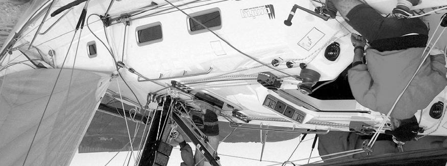
8 2.1 Installing the instrument Place the adhesive drill template on the desired location for the instrument. Drill the 4 screw holes using a 2.8 mm ( 7 / 64 ") drill for wood or 3.2 mm ( 1 / 8 ") for fibre glass. Use a 63 mm (2½") hole saw to machine the clearance hole for the instrument connection socket. Remove the template. Note: Never drill through the instruments 4 mounting holes as the gaskets may be damaged and thus cause leakage. The warranty is not valid for damage caused by drilling through the mounting holes. Run the cable from the Mast head unit to the instrument. Cut the cable to length. Peel off about 35 mm (1,4") of the cable insulation. Remove about 6 mm (1/4") from the 3 isolated wires (the 4th wire is an earth / screen). Attach the 4 cable protectors to the wires using a pair of flat pliers. Connect the 4 cable protectors to the 4-pole jack plug as shown. Apply silicon paste on all locations as shown. Silicon paste Silicon paste Note: Must be done to avoid corrosion. Apply silicon paste to the instrument connection pins at the back of the instrument. Press the jack plug onto the instrument pins. Press down the cable in the cable leads. Mount the connection back cover with the screw. Mount the instrument in the pre-drilled position. Note! Use all 4 screws, and tighten the screws (in cross pattern) so the gasket will be evenly compressed to 1/3 of its original thickness. Very important for a correct sealing to avoid leakage! Press on the 4 rubber caps to seal and hide the mounting screws. Your instrument installation is done! 7
9 2.2 Installing cable The power cable is connected via a 3A fuse from the battery or at the boats fuse panel and direct to the instrument or Server. One red and one black power wire is included. Always connect a 3 AMP fuse between Power supply and instrument. Screen Green Yellow Black White Red A B T L 3A Fuse 2.3 Connection of log transducer If you have an other log instrument i.e. a Star log or Star Set, you may connect the single log pulse wire from that instrument to the Wind instrument terminal 4. A B T L From log instrument, yellow from transducer 3A Fuse 8
10 3 Operation 3.1 About this manual Each time a push-button are referred to in this manual, the push-button name will appear in bold and CAPITAL letters, e.g. MODE. Unless otherwise stated, the push-button presses are momentary. Each time a function is mentioned in the text, it will be in brackets and in the same format, where possible, as displayed, e.g. [AWA]. This manual has been written to be: Compatible with Wind instrument from software version 1.0. All functions followed by the text option is not valid in a factory set-up instrument. See calibration to be able to display these functions. Note! We have put down a lot of effort in order to make this manual correct and complete. But since we continuously make our products better, some information can differ from the products functions. If you need further information contact your national distributor 9

11 3.2 How to use the 4 push-buttons MAIN FUNCTION INFOTEXT SUB- FUNCTION APPARENT ANGLE TRUE ANGLE TRIM FUNCTION MODE DOWN UP KEY MODE A press on MODE change the mode of the graphical display. It scrolls in a circular pattern, one step for every press. The MODE button is also used to move the cursor when in edit mode. A press on MODE moves the cursor in a circular pattern, one step to the right for every press. A press on MODE and DOWN together, back steps cursor to the preceding step. When in editing mode a long press (>2sec) on MODE will escape from that editing mode DOWN A press on DOWN moves to the next sub-function. In edit mode it decreases to previous digit UP A press on UP moves to the previous sub-function. In edit mode it increases to next digit KEY A press on KEY unlocks a digit to access edit mode. When unlocked, the digits are active (flashes) and can be edited by pressing DOWN, UP and MODE as required. When finished editing, lock the digit by another press on KEY Clear A press on DOWN and UP together, clear digits. 10
12 1.1.5 Calibration To access calibration mode, press and hold KEY more than 2 seconds. To return to main function mode, press KEY when the text return [RET] is shown Lighting The instrument uses red back lighting for the display and the 4 push-buttons. The lighting can be set at 4 different levels. To access the light control, press and hold MODE for more than 2 seconds. The flashing text [Lit OFF] will be displayed and the display will be lit momentarily. To select between the 4 light levels, press UP: [LOW], [MID], [MAX] and [OFF]. To lock the selected level, press KEY. 11
13 3.3 Main function Top data is relative Wind angle, [AWA] (Apparent Wind Angle). As an alternative to [AWA] the following can be displayed: [AWS] (Apparent Wind Speed). [TWA] (True Wind Angle) if the log transducer is connected. [TWS] (True Wind Speed) if the log transducer is connected. To change between these functions, see C12, Analogue function Change Wind scale between 180 and 60 with MODE. Selected scale is shown with the LCD arrow pointing at scale. The text [APP] displays selected main function as apparent Wind angle or Wind speed. MIX 180 The text MIX 180 means that both APP and TRUE Wind angle is displayed in scale 180. MIX 60 The text MIX 60 means that both APP and TRUE is displayed in scale 60. The scale can be altered between 60 and 180 to get more accurate readings. At scale 180 each sector represent 5 and at scale 60 each sector represent 1 2 / 3. See the example below. 12
14 3.5 Sub-functions Select sub-function with UP or DOWN. Information text for the sub-function is displayed. You may also park your favourite function so it will automatically be displayed after power on. Press both MODE and KEY to park the displayed function. The display will flash once to confirm that you have parked the function Apparent Wind Speed [AWS] The text [AWS] (Apparent Wind Speed) and its value is displayed below. The text [AWS] is toggled with the text [KTS] (KnoTS), [M/S] (Metres/S) or [BF] (Beaufort) True Wind Speed [TWS] The text [TWS] (True Wind Speed) and its value is displayed below. The text [TWS] (True Wind Speed) is toggled with the text [KTS] (KnoTS), [M/S] (Metres/s) or [BF] (BeauFort) True maximum Wind speed Press the KEY in the sub-function: [TWS] to display maximum true Wind speed. After 5 seconds the display will go back to [TWS] again. Re-set or clear the [MAX] Wind speed value by pressing UP and DOWN together or switch off the power Velocity Made Good (VMG) The text [VMG] (Velocity Made Good) is displayed with the actual boat speed towards or against the Wind. The water speed information from the log transducer is needed. The speed information must be taken from the Star log if connected. VMG = 0.0 knots when the true Wind angle is perpendicular to the boat. 13
15 3.5.5 Battery voltage [BAT], option The text [BAT] will display battery voltage. The voltage is measured inside the instrument and will not compensate for any voltage drop caused by installation Boat speed [BSP], option The text [BSP] will display boat speed (water speed). The text [BSP] will toggle with selected unit, i.e. (KTS), (KMH) or (MPH). As an option, you may add or remove displaying boat speed [BSP], trip log [TRP] and water temperature [TMP]. See further under calibration Trip log [TRP], option The text [TRP] is displayed and will show trip distance from 0.00 to 99.9 nautical miles, kilometre or miles. After 99.9, 0.00 is displayed. Clear trip by pressing UP and DOWN together Water temperature [TMP], option The text [TMP] is displayed with water temperature in Celsius or Fahrenheit. This function requires a Star log transducer Trim function for optimum Wind angle or speed, option The text [TRM] and [OFF] is displayed when this function is off. The trim function can be used as an aid to keep the correct tacking angle or to discover speed changes caused by sail or rig trimming. As the first example we will use [TRM AWA] (TRiM Apparent Wind Angle). To trim on Wind angle deviation, select the text: Press UP and DOWN together, the display will flash. Select [AWA] with DOWN and confirm with KEY. Select the level of dampening [d0-d9] and confirm with the KEY. The default (or latest used) Wind angle is displayed. You may accept the proposed angle by pressing the KEY or enter a new Wind angle with UP, DOWN and MODE before confirming with KEY. 14
16 The entered Wind angle will be lost when power off. You may however select a default Wind angle in set-up. See C Every time you select this function, or after power up, the preset value is proposed. On the display you will see the text TRM and AWA toggling together with your Wind angle. On the graphic part you will see your reference angle as one straight horizontal segment when actual angle is equal to the pre-set angle. At the same time you will see apparent and true Wind angle. The deviation is displayed visible upwards or downwards from the horizontal line to +/-15. The maximum visible deviation is 15. When the deviation is between 15 and 30 the 15 sector is lit. When larger then 30 the segment sector is blanked out. Trim on speed: Select the trim function. Press UP and DOWN together. Select text (BSP) by pressing UP and confirm with KEY. Each sector represents 2 There is a number of different speeds to be used for trimming. The most common is [BSP] (Boat SPeed) and [VMG] (Velocity Made Good). The TBS is normally calculated by use of polar diagram on PC with racing software. The value Target Boat Speed is transmitted through the Nexus Server on the NMEA 0183 input. The Server will then transmit TBS on the Nexus Network. On the Wind display you will see both the digital value in % and the graphical value as a 2% variation for each segment. You may select speeds to TRIM, from this list: BSP Boat speed Log transducer! AWS Apparent Wind Speed TWS True Wind Speed Log transducer! VMG Velocity Made Good Log transducer! OFF Function is OFF When [BSP] (or other function) is selected, the dampening [d3] is flashing. Select dampening level and confirm with KEY. The text [% OFF] is then displayed to show that the function is selected, but no reference is yet set. 15
17 Press KEY to set [BSP] reference. The display will now show you the text [%] toggling with text [BSP] or whatever trim you have selected. The speed variation is expressed in % from set value. Press the KEY every time you wish to set a new trim reference value. There is an option to use an external trim button to set a new trim reference. See more in the calibration. Each sector represents 2% 16
18 4 Calibration To get the most out of your Nexus instrument, it is important to carefully calibrate the instrument. The calibration values are stored in a non volatile memory. To access calibration mode, press and hold KEY more than 2 seconds. To select a calibration code, press DOWN, UP and MODE as required. To return to normal operation mode, press KEY when the text return (RET) is displayed. The different calibration routines are divided into five groups: C10 - C15 = USR, User settings. C20 - C24 = BSP, Log transducer and temp calibrations. C50 - C64 = WND, Wind transducer settings/calibrations. C70 - C74 = CON, Configuration. To change a calibration value, press KEY. To select calibration value, press DOWN, UP and MODE as required. To lock the selected value, press KEY. 4.1 C10 User settings To return to normal mode, press KEY when the text [ret] is displayed C11 Select the dampening The dampening will affect Wind angle, Wind speed, boat speed and VMG. Dampening is between d0 (0s) and d9 (1 20). To change the dampening, press KEY and change with UP or DOWN and enter with KEY C12 Select main information Select function to be display at the top left of the LCD display. There is five options. AWA Apparent Wind Angle. TWA AWS TWS True Wind angle by the use of log transducer. Apparent Wind speed. True Wind speed by use of log transducer. 17
19 4.1.3 C13 Displaying boat speed, trip log and temperature, option When set to OFF, the functions will be removed from the display C15 Beep when key is pressed Setting On will make a beep at every key press, while OFF is silent. 4.2 C20 Calibration of Log To return to normal mode, press KEY when the text [ret] is displayed C21 Select unit for speed Unit for speed, knots (KTS), km/h (K/h) or miles/h (m/h) C22 Calibration of log transducer Calibration value for speed and distance ( ). Drive the boat a measured distance at normal speed. Compare the distance with the trip counter. Calculate the value with the following formula. True distance from the sea chart: Log trip counter distance: The current calibration value: New calibration value: T L C N If you suspect a current in the water, drive the boat in both directions and divide trip counter distance by two. If the Star Log is already calibrated, you must enter the same calibration value as for the Star Log C23 Unit for temperature Select degree Celsius [C] or degree Fahrenheit [F] C24 Temperature offset By adding a positive or [-] negative value here, it will be added as an offset before displayed as the temperature. 18
20 4.3 C50 Wind Settings To return to normal mode, press KEY when the text [ret] is displayed C52 Unit for Wind speed Unit for Wind speed [KTS] for (KnoTS), [M/S] for (Metres/S) and [BF] for (Beaufort) C53 Wind speed calibration Do not change this factory setting C54 Adjustment of Wind angle Mast top unit misalignment adjust value or the so called Afault, makes it possible to adjust any horizontal angle. Example: If the Wind angle is +4 when you sail/drive the boat straight into the Wind, set the calibration value in C54 to C55-C62 Calibration table for the Wind transducer In channels C55 to C62 you set the calibration values for the mast top unit. Each mast top unit is individually calibrated for best accuracy. See the separate Wind calibration certificate supplied with each mast top unit. Each of the inter-cardinal directions are calibrated. C C C C C C C C Set the calibration value according to the provided calibration certificate 19
21 4.4 C70 Configure the system To return to normal mode, press KEY when the text [ret] is displayed C74 Demo mode The Wind instrument has a built in demonstration mode. All values are simulated in this mode. It is convenient to learn the functions of the instrument by using this mode. Every 7th second the text DEM will appear to alert you that demo mode is selected. 20
22 5 Maintenance and fault finding 5.1 Maintenance To clean the instrument, use only mild soap solution and rinse with water. Do not use detergents or high pressure washing equipment. At least once a year, check all your connections and apply additional silicon paste at each connection point. Always use the instrument cover for protection, when not in use. Storing transducers and instruments when not in use for longer periods: It is advisable to remove the instruments and transducers, and store them inside the boat or at home in room temperature, if possible. 5.2 Fault finding Before you contact your Silva dealer, and to assist your dealer to give you a better service, please check the following points and make a list of: All connected instrument and transducers, including their software version numbers. Instrument software version number General In most cases, the reason for faults in electronic equipment is the installation or poor connections. Therefore, always first check that: Installation and connection is made per instructions for instrument and transducers, (see 2.1). Screw terminals are carefully tightened. No corrosion on any connection points. No loose ends in the wires causing short cuts to adjacent wires. Cables for damage, that no cables are squeezed or worn. Battery voltage is sufficient, should be at least 10 V DC. The fuse is not blown and the circuit-breaker has not opened. The fuse is of the right type. 21
23 5.2.2 Fault - action 1. Wind: No reading [ --- ] If inaccurate Wind is received, check the connections (separate through deck connection or below decks connection), are properly made. Make sure the transducer is aligned correctly, (see C54, 4.3.3). Measure with a voltmeter, at the screw terminal pin 1 and ground, and between pin 2 and ground. If the voltmeter shows 1.5 to 4 V DC (minimum Wind speed 3 m/s) at both measuring points, the transducer and the connections are OK. If the voltmeter shows 0 or 5 V DC at both measuring points, the transducer or the connections are defect. Contact you Silva dealer with this information. 2. Speed and distance functions: No reading [ --- ] C13 should be ON. See If you have a voltmeter available, you can check the condition of the transducer. When measuring with voltmeter make sure everything is connected, that the power is on and make sure the paddle wheel is rotating. At the back of the instrument, measure between pin 4 and ground. When not rotating, the value should be fixed at either about 0 or 5 V DC. When rotating very slowly, by hand, the value should flip between 0 and 5 V DC. When rotating faster, the value should average around 2.5 V DC. Irregular values: Check the speed damping (SEA), (see C11, 4.1.1) Error messages The following error messages can appear on the display: ERROR 10 Range error caused by bad format, e.g ERROR 11 Remote command that can not be performed. If other error messages than the above appears on the Wind instrument, contact your Silva dealer. 22
24 6 Specifications 6.1 Technical specifications Dimensions: Instrument cable: Power supply: Power consumption Instrument: Log- and temp sensor: Wind transducer: Temperature range: Weight: Enclosure: Wind instrument: 110 x 110 mm. (4.3x4.3 inch) 12 V DC (10-16 V). The instrument is polarity protected. 0,08 W 0.8 W (at max illumination) 12 mw 50 mw Storage: From -30 C to +80 C.( -22 F to 176 F) Operation: From -10 C to +70 C. (14 F to 158 F) Instrument: 283 g (9.98 oz). Transducer: 293 g (10.33 oz). Instrument. Water proof CE approval The products conforms to the EMC requirements for immunity and emission according to EN , 23
25 7 Abbreviations BSP Boat Speed BTW Bearing To Waypoint C Celsius F Fahrenheit KM KiloMetre KTS KnoTS MH Miles per Hour LCD Liquid Crystal Display LOW LOW MID MID MAX MAX RET RETurn SOG Speed Over Ground TRP TRiP - Minus _ Plus 24

26 8 Warranty 25
27 26
28 27
Part specifications...6 Installation...8 Installing the instrument...9 First start (only in a Nexus Network)...13 Operation...14 Calibration...
...13 Operation...14 Calibration...") 0 1 2 Introduction Thank you for choosing FI-30 Wind Data instrument. We are convinced that you will appreciate all the valuable information either you are a cruiser or a racer. It is important that you
0 1 2 Introduction Thank you for choosing FI-30 Wind Data instrument. We are convinced that you will appreciate all the valuable information either you are a cruiser or a racer. It is important that you
performance by NEXUS NETWORK WIND Data - Instrument - Installation and Operation Manual English
 performance by NEXUS NETWORK WIND Data - Instrument - Installation and Operation Manual English 4-1 Introduction Thank you for choosing NX2 Wind Data instrument. We are convinced that you will appreciate
INTRODUCTION TO NETWORK WIND 3 MOUNTING THE UNIT 14 SELECTING THE DISPLAY MODE 5 ABBREVIATIONS AND DEFINITIONS 17
 CONTENTS CONTENTS 1 INSTALLATION 14 GENERAL INTRODUCTION TO B&G NETWORK 2 SITING THE UNIT 14 INTRODUCTION TO NETWORK WIND 3 MOUNTING THE UNIT 14 EXAMPLE SYSTEMS USING NETWORK WIND 4 SPECIFICATION 16 SELECTING
Compass. - Instrument - Installation and Operation Manual English
 Compass - Instrument - Installation and Operation Manual COMPASS 5-1 COMPASS Introduction Thank you for choosing NX2 Compass instrument. We are convinced that you will appreciate all the valuable information
performance by NEXUS NETWORK Compass - Instrument - Installation and Operation Manual English
 performance by NEXUS NETWORK Compass - Instrument - Installation and Operation Manual COMPASS 5-1 COMPASS Introduction Thank you for choosing NX2 Compass instrument. We are convinced that you will appreciate
- Instrument and Server - Installation and Operation Manual
 - Instrument and Server - Installation and Operation Manual 0 Navigation terms BOD: Bearing origin destination BTW: Bearing to Waypoint CMG: Course made good COG. Course over ground CTS: Course to steer
TOP BLEED Position for SeaTalk 2 colour logo ST 30. COMPASS Operation and Installation
 Distributed by Any reference to Raytheon or RTN in this manual should be interpreted as Raymarine. The names Raytheon and RTN are owned by the Raytheon Company. TOP BLEED Position for SeaTalk 2 colour
Multi Control - Instrument -
 Multi Control - Instrument - Installation and Operation Manual English English 1 Navigation terms 2 This manual is written for NX2 Multi Control version 3.1 5.0 Edition: March 2007 3 1 Part specification...
WIND CLIPPER KTS ILLUM SCALE INC DEC CLIPPER WIND SYSTEM
 CLIPPER WIND KTS ILLUM SCALE DEC INC CLIPPER WIND SYSTEM TABLE OF CONTENTS INTRODUCTION PRE-TEST OF INSTRUMENT INSTALLING THE MASTHEAD SENSOR UNIT INSTALLING THE DISPLAY NORMAL OPERATION CHANGING THE
INSTALLING THE ECHO SOUNDER TRANSDUCER CHANGING THE OPERATING CONFIGURATION
 INTRODUCTION INSTALLING THE DISPLAY INSTALLING THE LOG PADDLE WHEEL UNIT INSTALLING THE ECHO SOUNDER TRANSDUCER NOTES ON ELECTRICAL INTERFERENCE USING THE INSTRUMENT SETTING THE MINIMUM DEPTH ALARM SETTING
PART 5 - OPTIONS CONTENTS 5.1 SYSTEM EXPANSION 5-3
 PART 5 - OPTIONS CONTENTS Para Page 5.1 SYSTEM EXPANSION 5-3 5.2 SENSORS 5-3 5.2.1 Trim Angle Sensor 5-3 5.2.2 Mast Rotation Sensor 5-3 5.2.3 Heel Angle Sensor 5-3 5.2.4 Barometric Pressure Sensor 5-3
GNX Wind. Owner s Manual
 GNX Wind Owner s Manual February 2016 190-02003-00_0A All rights reserved. Under the copyright laws, this manual may not be copied, in whole or in part, without the written consent of Garmin. Garmin reserves
mn100 Analog Display
 mn100 Analog Display uu040 rev. 8 mn100 Analog Display EMC Conformance All Tacktick equipment is designed to the best industry standards for use in the recreational marine environment. The design and manufacture
Copyright 2004 by the Thomas G. Faria Corporation, Uncasville CT No part of this publication may by reproduced in any form, in an electronic
 Copyright 2004 by the Thomas G. Faria Corporation, Uncasville CT No part of this publication may by reproduced in any form, in an electronic retrieval system or otherwise, without the prior written permission
USER GUIDE FOR DATALINE-X SDX. Stowe Marine Ltd. Tel +44(0)
") USER GUIDE FOR DATALINE-X SDX Stowe Marine Ltd. www.stowemarine.com Tel +44(0)1590 610071 Dataline-X SDX Manual, Part Number 05707SM, Issue 2, Dec 1995. Warning The equipment to which this manual applies
USER GUIDE FOR DATALINE-X SDX Stowe Marine Ltd. www.stowemarine.com Tel +44(0)1590 610071 Dataline-X SDX Manual, Part Number 05707SM, Issue 2, Dec 1995. Warning The equipment to which this manual applies
ECHO MANUAL WARNING. L B A ltim e te rs. ECHO is a trademark of LB Altimeters, Denmark
 ECHO MANUAL L B A ltim e te rs ECHO is a trademark of LB Altimeters, Denmark LB Altimeters operates a policy of continuous development Therefore, we reserve the right to make changes and improvements to
ST40 Bidata Instrument Owner s Handbook. Document number: Date: March 2006
 Bidata Instrument Owner s Handbook Document number: 81159-3 Date: March 2006 Raymarine, and SeaTalk are trademarks of Raymarine UK Ltd Handbook contents copyright Raymarine UK Ltd. Preface i Important
frequently asked questions
 Hydra Pilot Fault Codes What do the fault codes for the Hydra Pilot mean? Fault Cause FAULT 100 FAULT 101 FAULT 102 FAULT 103 FAULT 104 FAULT 105 FAULT 106 FAULT 108 FAULT 109 FAULT 110 FAULT 111 FAULT
Before installing to a boat of aluminum or steel construction, please contact your Tacktick dealer.
 Analogue Display mn100 Analogue Display EMC Conformance All Tacktick equipment is designed to the best industry standards for use in the recreational marine environment. The design and manufacture of Tacktick
Depth sensor. Product reference : REV 1. USER GUIDE and INSTALLATION GUIDE. nke Sailing competition
 Depth sensor Product reference : 90-60-456 REV 1 USER GUIDE and INSTALLATION GUIDE nke Sailing competition Z.I. Kerandré Rue Gutenberg 56700 HENNEBONT- FRANCE http://www.nke.fr After sale service n 33
Sail Racing Instruments. Aspect 40
 Sail Racing Instruments www.nexusmarine.se Presentation Nexus Marine is a leading manufacturer of navigation instrumentation for racing and cruising yachts. Nexus brings with it seventy years of experience
Operating Instructions Part No
 DIGITAL AUTOMATIC TYRE INFLATOR Operating Instructions Part No. 11.0578 Thank you for selecting this Jamec Pem Automatic Tyre Inflator. Please read this manual before carrying out any installation or service
SG33KTL-M Quick Installation Guide. 1 Unpacking and Inspection
 SG33KTL-M Quick Installation Guide This guide provides a general instruction of the installation procedures of SG33KTL-M. In no case shall this guide substitute for the user manual or related notes on
SG36KTL-M Quick Installation Guide. 1 Unpacking and Inspection
 SG36KTL-M Quick Installation Guide This guide provides a general instruction of the installation procedures of SG36KTL-M. In no case shall this guide substitute for the user manual or related notes on
GNX 120/130. Owner s Manual
 GNX 120/130 Owner s Manual March 2016 190-01846-00_0B All rights reserved. Under the copyright laws, this manual may not be copied, in whole or in part, without the written consent of Garmin. Garmin reserves
Digital Melting Point Apparatus
 Digital Melting Point Apparatus Heating Plateau Ramping Start/Stop Plateau set Ramp stop Hold User Guide Version 1.1 Heating Viewing tube Sample Chamber IEC power inlet socket Power on/off Temperature
EMC Conformance. Important
 Digital Display mn100 Digital Display EMC Conformance All Raymarine equipment is designed to the best industry standards for use in the recreational marine environment. The design and manufacture of Raymarine
GNX 20/21. Owner s Manual
 GNX 20/21 Owner s Manual Table of Contents Introduction...1 Device Overview... 1 Using the Race Timer... 1 Profiles... 1 Selecting a Profile... 1 Restoring Profiles to their Default Settings... 1 Instrument
ST60 Depth Instrument Owner s Handbook. Document number: Date: 1 April 2004
 ST60 Depth Instrument Owner s Handbook Document number: 81038-4 Date: 1 April 2004 Raymarine, ST60 and SeaTalk are trademarks of Raymarine Limited Handbook contents copyright Raymarine Limited 2004 Preface
Instructions for Use
 Select-380 T-Auto T-Auto Contents Page Instructions for Use Ref: 3.0 IFU 380 T-Auto Mar 18 2 Schematic layout of the doser 3 Quick-fit instructions 4 Description/Installation/Operation Pump tubes & Water
- Course Processor R
 http://nex / /Autopilot/dig_auto.tif Autopilot - Course Processor R-1600 - Installation and Operation Manual AUTOPILOT 8-1 AUTOPILOT This manual is written for NX2 Autopilot version 1.00 Edition: May 2012
METEOR LSR36500 LIGHTING UNDERWATER POOL LIGHT. Operating Instructions
 METEOR LSR36500 UNDERWATER POOL LIGHT Operating Instructions LIGHTING CONTENTS Preface...3 Features...3 Precautions...3 Components and Connectors...4 Installation...5 Controls...7 Appearance...8 Technical
OPERATION AND INSTALLATION MANUAL
 AP46 Autopilot OPERATION AND INSTALLATION MANUAL www.tmq.com.au TMQ AP46 Autopilot Page 1 of 34 Ver1.0 07/03/2007 This page is Blank TMQ AP46 Autopilot Page 2 of 34 Ver1.0 07/03/2007 WARNING!...4 INTRODUCTION...5
Manual Weighingblock VB2 series and Uniscale
 Manual Weighingblock VB2 series and Uniscale Note: At page 8 in this manual you will find a short form instruction. Normally the only instruction shipped together with the Scale. Overview different ranges.
STARLOG. Capacitive Water Depth Probe
 STARLOG Capacitive Water Depth Probe Model 6521 User Manual Supplement 6219 Revision D July 10. 1998 Copyright Notice Copyright Unidata Australia 1998. All rights reserved. No part of this publication
GV Standard X-Vent. Setup, Commissioning & Installation Guide
 GV Standard X-Vent Setup, Commissioning & Installation Guide Technical experts in the design, manufacture and supply of precision engineered, architectural rooflights for residential and commercial buildings.
ST60+ Depth Instrument Owner s Handbook
 ST60+ Depth Instrument Owner s Handbook Document reference: 81262-2 Date: December 2005 Raymarine, ST60+ and SeaTalk are trademarks of Raymarine UK Limited Handbook contents copyright Raymarine UK Limited
OEM Manual. MODEL ½ Digit DRUM SCALE
 OEM Manual MODEL 4020-3 ½ Digit DRUM SCALE Scaletron Industries, Ltd. Bedminster Industrial Park 53 Apple Tree Lane P.O. Box 365 Plumsteadville, PA 18949 USA Toll Free: 1-800-257-5911 (USA & Canada) Phone:
OxyScan Graphic. Operating Instructions. UMS Micro-oxygen sensor 501. Microprocessor instrument
 OxyScan Graphic Operating Instructions UMS Micro-oxygen sensor 501 Microprocessor instrument Introduction Thank you for choosing the UMS Micro Oxygen Sensor 501 - a highly advanced product! Please read
TS-202 FFU Lever Remote Part Number & Operation & Installation Instructions Version 2.1
 R TS-202 FFU Lever Remote Part Number 20310020 & 20310029 Operation & Installation Instructions Version 2.1 ComNav Marine Ltd. 15 13511 Crestwood Place. Richmond, B.C. Canada. V6V-2G1 Document PN 29010046
S1000+ / S2000+ Tiller Pilots
 S1000+ / S2000+ Tiller Pilots Owner s handbook English Date: 12-2013 Document number: 81130-7-EN 2013 Raymarine UK Limited 1 Contents Contents... 1 Chapter 1: Introduction...3 1.1 Overview... 3 1.2 Specifications...
Operating Instructions Part No
 DIGITAL AUTOMATIC TYRE INFLATOR Operating Instructions Part No. 11.0545 Thank you for selecting this Jamec Pem Automatic Tyre Inflator. Please read this manual before carrying out any installation or service
Model 130M Pneumatic Controller
 Instruction MI 017-450 May 1978 Model 130M Pneumatic Controller Installation and Operation Manual Control Unit Controller Model 130M Controller is a pneumatic, shelf-mounted instrument with a separate
GNX 20/21. Owner s Manual
 GNX 20/21 Owner s Manual March 2016 190-01659-00_0C All rights reserved. Under the copyright laws, this manual may not be copied, in whole or in part, without the written consent of Garmin. Garmin reserves
UsER manual for Watersens ph -REDOX
 UsER manual for Watersens -REDOX Cl 8 1 2 6 3 3 7 7 4 4 4 4 Parts List 1 Redox Probe 1 x 2 PH Probe 1 x 5 Tube Weight 2 x 6 Connection Valve 1 x chlorine 3 Chlorine and Pumps 2 x 7 Dosing Valve 2 x 5 5
icreasepro Creaser Operators Manual
 6-2013 Version 3.0 icreasepro Creaser Operators Manual WWW.MBMCORP.COM 800-223-2508 TABLE OF CONTENTS SPECIFICATIONS.1a SAFETY PROCEDURES/CARE & MAINTENANCE..1b COMPONENT IDENTIFICATION 2 TOUCH SCREEN
D10S/D20S Wall/Post Mount Inflator Quick Start Manual
 PART NUMBER SERIAL NUMBER D10S/D20S Wall/Post Mount Inflator Quick Start Manual Please read and save these instructions. Read carefully before attempting to assemble, install, operate or maintain the product
AIR FLOW ANEMOMETER INSTRUCTION MANUAL
 AIR FLOW ANEMOMETER INSTRUCTION MANUAL Thank you for purchasing our company Air Flow Anemometer. This manual provides relative information on how to use the Air Anemometer and warning in operation Please
ST1000 Plus & ST2000 Plus Tiller Pilots Owner s Handbook. Document number: Date: June 2001
 Distributed by Any reference to Raytheon or RTN in this manual should be interpreted as Raymarine. The names Raytheon and RTN are owned by the Raytheon Company. ST1000 Plus & ST2000 Plus Tiller Pilots
EC214 EC215 - EC215R Bench Conductivity Meters
 Instruction Manual EC214 EC215 - EC215R Bench Conductivity Meters http://www.hannainst.com These Instruments are in Compliance with the CE Directives Dear Customer, Thank you for choosing a Hanna Instruments
Installation, operating and maintenance Instructions for Seemag bypass level indicator
 Issue: S Date: 05-09-14 Type G35 General information The Seetru bypass magnetic level indicator, abbreviate SEEMAG, serves to show the filling level of fluids in tanks, basins, tubes etc. The Seemag operates
Dual Digital Display
 Dual Digital Display mn100 Dual Digital Display EMC Conformance All Tacktick equipment is designed to the best industry standards for use in the recreational marine environment. The design and manufacture
WELCOME TO THE REVOLUTION
 USER GUIDE WELCOME TO THE REVOLUTION THANK YOU FOR CHOOSING THE GCQUAD We listened to what you wanted - and created the most accurate, versatile and game-enhancing ball and club analysis solution available
ST30 Round Bidata Owner s Handbook
 ST30 Round Bidata Owner s Handbook Document number: 81075_4 Date: 1st April 2001 Copyright Raymarine Limited 2001 Preface i Important information WARNING Although your ST30 instrument is designed to give
Steer to Wind angle, Wind Mode, when connected to the h1000 Wind Interface
 h1000 pilot introduction overview Congratulations on your purchase of the h1000 Pilot from B&G. The h1000 Pilot is the latest in autopilots from B&G and represents B&G s commitment to providing our customers
UBEC 1AT. AUTO TANK Fill System Installation, Operation, & Setup Instructions
 Document Number: XE-ATA5PM-R1A UBEC 1AT AUTO TANK Fill System 08899155 Installation, Operation, & Setup Instructions Rev170906-EB-FRC PHYSICAL: 1302 WEST BEARDSLEY AVE ELKHART, IN 46514 WWW.ELKHARTBRASS.COM
Tacktick Wireless Instruments
 Tacktick Wireless Instruments 2 The wireless revolution has already begun Across the globe, sailors and boat owners are experiencing the benefits of Tacktick s groundbreaking Micronet wireless and solar
100C Air Compressor Kit
 10010 100C Air Compressor (standard mounting bracket, CE Spec) 10014 100C Air Compressor (no leader hose or check valve, CE Spec) 10016 100C Air Compressor (with Omega Bracket, CE Spec) IMPORTANT: It is
DRILL MONITOR DM-100 OPERATIONS MANUAL
 DRILL MONITOR DM-100 OPERATIONS MANUAL 1 INSTALLATION AND SETUP The Drill Monitor comes complete with the following parts: 1 Drill Monitor unit 1 Mounting bracket for Drill Monitor 1 Encoder 1 Encoder
Instruction and Practice Manual
 Instruction and Practice Manual Axiom Sports Manufacturing A Division of Fitec International 3525 Ridge Meadow Parkway Memphis, TN 38175 (901) 366-9144 www.axiomsports.com 1 Thank you for purchasing the
HI 2314 HI 2315 HI 23151
 Instruction Manual HI 2314 HI 2315 HI 23151 Multi-Range Conductivity Meters for Laboratories www.hannainst.com Dear Customer, Thank you for choosing a Hanna Instruments product. Please read this instruction
Napa Technology Trouble Shooting. For Premier & Premier PLUS Models
 Napa Technology Trouble Shooting For Premier & Premier PLUS Models Before contacting Napa Technology for support, please check if the problem and solution are found below: Machine Is Off & All LCD s are
AUTOMATIC TIRE INFLATOR # MW-60, MW-60-4WAY & MW-64HP
 USER MANUEL AUTOMATIC TIRE INFLATOR # MW-60, MW-60-4WAY & MW-64HP TIRE EQUIPMENT MANUFACTURER 1.866.409.RACK WWW.MARTINSINDUSTRIES.COM info@martinsindustries.com PARTS Verify that the following components
Installation, Compensation and Maintenance Instructions for. RITCHIE Compasses. Made In U.S.A
 Installation, Compensation and Maintenance Instructions for RITCHIE Compasses Made In U.S.A All Magnetic Compasses are vulnerable to magnetic interference, which will produce errors, called deviation.
iregatta User Manual
 iregatta User Manual iregatta User Manual This manual may not always be up to date with the latest version of iregatta available in Apples App Store, as minor additions or bug fixes may be published without
200 PSI COMPRESSORS - MODEL NUMBERS
 200 PSI COMPRESSORS - MODEL NUMBERS 380C AIR COMPRESSOR KIT PART NO. 38033 480C AIR COMPRESSOR KIT PART NO. 48043 380C 480C IMPORTANT: It is essential that you and any other operator of this product read
T i m i n g S y s t e m s. RACEAMERICA, Inc. P.O. Box 3469 Santa Clara, CA (408)
") RACEAMERICA T i m i n g S y s t e m s Demo Tree Controller Owner s Manual Models 3204D, 3204DW & 3204DX Rev D RACEAMERICA, Inc. P.O. Box 3469 Santa Clara, CA 95055-3469 (408) 988-6188 http://www.raceamerica.com
RACEAMERICA T i m i n g S y s t e m s Demo Tree Controller Owner s Manual Models 3204D, 3204DW & 3204DX Rev D RACEAMERICA, Inc. P.O. Box 3469 Santa Clara, CA 95055-3469 (408) 988-6188 http://www.raceamerica.com
444C DUAL PERFORMANCE VALUE PACK
 (Chrome) PART NO. 44432 IMPORTANT: It is essential that you and any other operator of this product read and understand the contents of this manual before installing and using this product. SAVE THIS MANUAL
Misaligned Folds Paper Feed Problems Double Feeds Won t Feed FLYER Won t Run iii
 Operator s Manual Table of Contents Operator Safety... 1 Introduction... 2 Unpacking and Setup... 3 Unpacking... 3 Setup... 4 FLYER Overview... 5 FLYER Diagram... 5 Capabilities... 5 Control Panel... 6
PROPORTIONING VALVE. Model 150 INSTRUCTION MANUAL. March 2017 IMS Company Stafford Road
 PROPORTIONING VALVE Model 150 INSTRUCTION MANUAL March 2017 IMS Company 10373 Stafford Road Telephone: (440) 543-1615 Fax: (440) 543-1069 Email: sales@imscompany.com 1 Introduction IMS Company reserves
Manufactured by: AAA
 Manufactured by: AAA The Altitron Skydiving Altimeter is an advanced digital altimeter. It is designed to effectively improve safety and easily keep track of skydiving activity. It can be used as a mechanical
USER MANUAL. Premier Way, Abbey Park Romsey Hampshire, SO51 9DH, UK. Tel: (+44) Fax: (+44)
 Fax: (+44)") USER MANUAL Premier Way, Abbey Park Romsey Hampshire, SO51 9DH, UK Tel: (+44) 01590 689699 Fax: (+44) 01590 610072 www.bandgservice.co.uk Brookes and Gatehouse Ltd. 2000 The copyright of this Manual is
USER MANUAL Premier Way, Abbey Park Romsey Hampshire, SO51 9DH, UK Tel: (+44) 01590 689699 Fax: (+44) 01590 610072 www.bandgservice.co.uk Brookes and Gatehouse Ltd. 2000 The copyright of this Manual is
S1000+ / S2000+ Tiller Pilots. Owner s manual
 S1000+ / S2000+ Tiller Pilots Owner s manual Chapter 1: Introduction Chapter 1: Introduction 1.1 Overview D5557-2 Your Raymarine tiller pilot is a totally self-contained autopilot designed for tiller steered
CONTENTS STEER TO VANE MODE...
 CONTENTS GENERAL INTRODUCTION TO B&G NETWORK... 2 INTRODUCTION TO NETWORK PILOT... 3 SWITCHING THE NETWORK PILOT ON... 3 NETWORK PILOT DISPLAY UNIT... 4 NETWORK PILOT HAND-HELD CONTROLLER... 5 JOYSTICK
OEM Manual MODEL 2305 ECONOMICAL DIGITAL SINGLE CYLINDER SCALE
 OEM Manual MODEL 2305 ECONOMICAL DIGITAL SINGLE CYLINDER SCALE 1 These instructions generally describe the installation, operation, and maintenance of subject equipment. The manufacturer reserves the right
MP15 Jockey Pump Controller
 Setup and Operating Instructions MP15 Jockey Pump Controller This manual provides general information, installation, operation, maintenance, and system setup information for Metron Model MP15 Jockey Pump
Version-E E100930
 Version-E080529 E100930 Football Manual Important Information General Before using your ALGE-TIMING device read the complete manual carefully. It is part of the device and contains important information
97C COMPRESSOR KIT 12V PART NO C COMPRESSOR KIT 24V PART NO C COMPRESSOR KIT PART NO
 97C COMPRESSOR KIT 12V PART NO. 00097 97C COMPRESSOR KIT 24V PART NO. 02497 98C COMPRESSOR KIT PART NO. 00098 97C 98C IMPORTANT: It is essential that you and any other operator of this product read and
400C & 450C DUAL PERFORMANCE VALUE PACKS
 (Chrome) PART NO. 40013 (Silver) PART NO. 45012 (Chrome) PART NO. 45013 IMPORTANT: It is essential that you and any other operator of this product read and understand the contents of this manual before
MODEL 9875 STADIUM BASEBALL SCOREBOARD. Instruction Manual
 UNITEC MANUFACTURING DIVISION MODEL 9875 STADIUM BASEBALL SCOREBOARD (WITH INNING BY INNING SCORING) Instruction Manual Mailing Address: PO Box 260, Yorkville, NY 13495-0260 Plant Address: 34 Main Street,
Powermax machine-side reference guide For mechanized applications with Powermax1000, Powermax1250 and Powermax1650
 Powermax machine-side reference guide For mechanized applications with Powermax1000, Powermax1250 and Powermax1650 This Powermax machine-side reference guide is a supplement to your Operator Manual and
Autopilot setup. VRF (Virtual Rudder Feedback) calibration. Software setup NSS evo2 Installation Manual
 calibration. Software setup NSS evo2 Installation Manual") Autopilot setup Verifying the autopilot connection When an AC12N, AC42N, or SG05 is connected to the NSS evo2 system, the NSS evo2 will automatically detect the autopilot and an Autopilot menu icon will
Autopilot setup Verifying the autopilot connection When an AC12N, AC42N, or SG05 is connected to the NSS evo2 system, the NSS evo2 will automatically detect the autopilot and an Autopilot menu icon will
Race Master System User Guide
 User Guide EMC Conformance All Tacktick equipment is designed to the best industry standards for use in the recreational marine environment. The design and manufacture of Tacktick equipment conforms to
Data sheet Pressure switch type CS December 2001 DKACT.PD.P10.A B1119
 Pressure switch type CS December 2001 DKACT.PD.P10.A2.02 520B1119 Introduction Pressure switch type CS is part of the Danfoss pressure control range. All CS pressure switches have a built-in pressure-operated,
Calibration Gas Instrument INSTRUCTION MANUAL. Release I. Advanced Calibration Designs, Inc.
 Advanced Calibration Designs, Inc. Calibration Gas Instrument INSTRUCTION MANUAL Release I www.goacd.com Instruction Manual Gas Generator Release I TABLE OF CONTENTS I. General Description Page 2 II. Start-Up
A4 Operation Manual. Fig.1-1 Controller Socket Diagram
 A4 Operation Manual Safety Instruction Please read this manual carefully, also with related manual for the machinery before use the controller. For installing and operating the controller properly and
S100 Controller. User guide. English Date: Document number: EN 2006 Raymarine UK Limited
 S100 Controller User guide English Date: 06-2006 Document number: 81242-4-EN 2006 Raymarine UK Limited 1 - Getting Started Changing the Controller batteries... 5 The S100 Autopilot Controller... 6 How
HBLT-A1 LIQUID LEVEL SENSOR
 Instruction manual HBLT-A1 LIQUID LEVEL SENSOR for measuring liquid level in refrigerant vessels Instruction manual HBLT - A1 - Liquid level Transmitter (HBLT-A1-008-UK) 1 / 16 Contents Safety instructions...
Code AWC20HP Air Compressor
 Code 951816 AWC20HP Air Compressor Index of Contents Index of Contents 02 Declaration of Conformity 02 What s Included 03 Safety Precautions 03 Specifications (AWC20HP Air Compressor) 04 Assembly Instructions
Parts List. Description. Additional Considerations. Installation Instructions. Dual/Elite Hydraulic Treadmill Kit (supplied by EPI)
") Page 1 of 9 Parts List Dual/Elite Hydraulic Treadmill Kit (supplied by EPI) Qty Description Treadmill Body 1 Treadmill Power Unit (per Treadmill Body) 2 Treadmill Decks (per Treadmill Body) 1 Treadmill
Page 1 of 9 Parts List Dual/Elite Hydraulic Treadmill Kit (supplied by EPI) Qty Description Treadmill Body 1 Treadmill Power Unit (per Treadmill Body) 2 Treadmill Decks (per Treadmill Body) 1 Treadmill
IMPORTANT SAFETY INSTRUCTIONS
 IMPORTANT SAFETY INSTRUCTIONS CAUTION - To reduce risk of electrical shock: - Do not disassemble. Do not attempt repairs or modifications. Refer to qualified service agencies for all service and repairs.
420C AIR COMPRESSOR KIT PART NO C AIR COMPRESSOR KIT PART NO
 420C AIR COMPRESSOR KIT PART NO. 42042 460C AIR COMPRESSOR KIT PART NO. 46043 420C 460C IMPORTANT: It is essential that you and any other operator of this product read and understand the contents of this
1.0 General Guide WARNING!
 User Manual 1.0 General Guide Thank you for purchasing your new ADC. We recommend reading this manual, and practicing the operations before using your ADC in the field. The ADC is designed to provide you
Dual Maxi Display User Guide
 User Guide EMC Conformance All Tacktick equipment is designed to the best industry standards for use in the recreational marine environment. The design and manufacture of Tacktick equipment conforms to
A4s Operation Manual
 A4s Operation Manual Safety Instruction Please read this manual carefully, also with related manual for the machinery before use the controller. For installing and operating the controller properly and
GNX 20/21 Owner s Manual
 GNX 20/21 Owner s Manual February 2014 190-01659-00_0B Printed in Taiwan All rights reserved. Under the copyright laws, this manual may not be copied, in whole or in part, without the written consent of
300C/ 800C/ 990C Plus Series
 Ultrasonic Level Meter 300C/ 800C/ 990C Plus Series INSTRUCTION MANUAL (July, 2008) 1 SLM300C/ 800C/ 990C Plus Series July, 2008 Copyright IS Technologies Co., Ltd. All rights reserved. No part of this
OWNER S MANUAL. All PowaKaddy electric trolleys have been awarded the Quiet Mark by the Noise Abatement Society
 OWNER S MANUAL All PowaKaddy electric trolleys have been awarded the Quiet Mark by the Noise Abatement Society Thank you for purchasing the new PowaKaddy. We hope you enjoy your new FW7s GPS trolley and
Installation, Operation and Maintenance Instructions for Electronically Controlled Pressurisation Units
 Installation, Operation and Maintenance Instructions for Electronically Controlled Pressurisation Units Models: EPS Single Pump EPT Twin Pump EPS-HP EPT-HP Single Pump High Pressure Twin Pump High Pressure
250C-IG COMPRESSOR KIT 12V PART NO C-IG COMPRESSOR KIT 24V PART NO
 250C-IG COMPRESSOR KIT 12V PART NO. 25050 250C-IG COMPRESSOR KIT 24V PART NO. 25058 IMPORTANT: It is essential that you and any other operator of this product read and understand the contents of this manual