Operating Instructions for Manometer. Model: MAN
|
|
|
- Alannah Houston
- 5 years ago
- Views:
Transcription

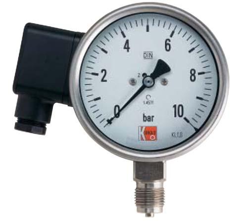
1 Operating Instructions for Manometer Model: MAN
2 1. Contents 1. Contents Note Instrument Inspection Regulation Use Operating Principle Mounting General Assembly for Differential Pressure Manometer Assembly for Contact Manometer Disassembly Sliding or Magnet-Spring Contacts General Contact Ratings Over-Current Protection Equipment Inductive and Electronic Contacts General Mode of Operation Electrical Data - Inductive Contact Electrical Data - Electronic Contact Commissioning General Adjustment of Set-Point Value with Contact Manometers Maintenance Cleaning Technical Information Declaration of Conformance...11 Manufactured and Marketed by: Kobold Messring GmbH Nordring D Hofheim Tel.: Fax: info.de@kobold.com Internet: Kobold-Messring GmbH Werk II Druck- und Temperaturmesstechnik Mahdentalstraße 44 D Sindelfingen Tel.: Fax: info.w2.de@kobold.com page 2 MAN 03/04
3 2. Note Please read these operating instructions before unpacking and putting the unit into operation. Follow the instructions precisely as described herein. The devices are only to be used, maintained and serviced by persons familiar with these operating instructions and in accordance with local regulations applying to Health & Safety and prevention of accidents. When used in machines, the measuring unit should be used only when the machines fulfil the EWG-machine guidelines. PED 97/23/EG In acc. with Article 3 Paragraph (3), "Sound Engineering Practice", of the PED 97/23/EC no CE mark. Model P max/bar Diagram 7 Group 2 no dangerous fluids Pipe Diagram 6 Group 1 dangerous fluids MAN < 200 Art. 3, 3 Art. 3, 3 MAN < 500 Art. 3, 3 Cat. I MAN < 1000 Art. 3, 3 Cat. I MAN > 1000 Cat. I Cat. I 3. Instrument Inspection Instruments are inspected before shipping and sent out in perfect condition. Should damage to a device be visible, we recommend a thorough inspection of the delivery packaging. In case of damage, please inform your parcel service / forwarding agent immediately, since they are responsible for damages during transit. The packing of material must be thoroughly searched, so that no accompanying accessories are thrown away. MAN 03/04 page 3
4 4. Regulation Use The units of the model MAN serve to measure and monitor pressure-dependent processes in machines systems. If applicable, the existing cap-holder on the connection body may be removed immediately before connecting measurement conductors, so that no foreign particles may find a chance to enter the pressure chamber. The storage of measurement unit should be arranged in a dry and dust-free area. 5. Operating Principle Depending on the measuring range as well as method of measurement (capsule, diaphragm, bourdon), the pressure to be measured is brought to display via a mechanical pointer attachment. The measuring element deforms in flexible range. 6. Mounting 6.1. General The assembly has to be carried out following the corresponding general technical regulations for pressure measuring devices (e.g. DIN or EN 837-2). While screwing in at the connection point, the necessary force may not be applied via the housing, instead only via key areas designated for such a purpose. The installation place of the pressure-gauges should be well accessible and close to the gas pressure measurements. If possible, above the measuring point. To avoid display deceleration time the distance between pressure withdrawal and pressure connection is to be kept small. Between pressure withdrawal point and measuring unit, a shut-off device is introduced which allows a renewal and null-point check of the running system. Up to the final commissioning, the shut-off equipment remains closed with the measurement piping. If pressure peaks are expected, a suitable protective equipment may be considered, such as pressure peak suppressor or a similar device. Alternatively, pressure measuring units with damping-liquid filling, for example, glycerine manometer may be provided. The piping up to the measuring unit should allow a vibration-free and stable attachment; in other case a wall holding or an additional fortification via an attachment brim on housing should be provided. Alternatively, mounting in a an instrument panel may be considered. page 4 MAN 03/04
5 The attachment of the manometer is to be executed in such a way that the admissible operating temperature does not violate min. and max. limits. In addition manometers and stop valve should be protected through sufficiently long measurement piping or water-bag pipes. The temperature influence can influence the display accuracy. With gauges for gas measurements, accumulation of condensation is to be avoided by suitable laying of piping. If the device for operational reasons cannot be attached above the measuring point, a drainage possibility is to be provided. An additional liquid column may affect the gauge only if this pressure is noted on the scale. In the unfavourable case, the result of measurement is falsified. For sealing of measuring unit's connections, sealing disks or sealing-edge-rings are utilised. The connection is recommended with stress-sockets or union-nuts; with that the manometer can be placed in the best reading position. During screw-in or screw-out, the force must not be exerted on the manometer housing, rather applied only over the four hexagonal connection-clips. Before attaching the gauges, the measuring piping should be cleaned with the Medium to be measured or with clean compressed air. While squeezing off or blowing through the piping or containers, the gauge may not be over-pressed. If the expected pressure is higher, the manometer must be removed or locked off Assembly for Differential Pressure Manometer Pressure-difference manometers have two pressure connections. On + marked pressure connection, connect higher than expected measuring pressure, on - marked pressure connection, connect lower than expected pressure. In order to protect the unit, a pressure compensation valve is to be provided. Through this valve, during commissioning or out of operation state of pressuredifference manometer, the measuring chambers on both sides of the measuring members are coupled among each other, and foremost if both pressure lines are open or closed, separated from each other. By means of this, a single-sided stress and thereby a possible overloading of measuring members is avoided Assembly for Contact Manometer In order to avoid bouncing of closed switch and thus resulting increase in wear, care should be taken during installation such that the units remain vibration-free. If the measuring-point is not sufficiently stable, a transmission line with one of the measuring unit's mounting, separated from the measuring-point should be provided. The units should be protected against coarse contamination strong variations of ambient temperature. MAN 03/04 page 5
6 6.4. Disassembly Before disassembling the pressure-measuring unit, the machine/equipment should be rendered in a pressure-less state. If possible, the measuring pipe should be emptied. In case of flat-spring manometers, step-in screws between upper and lower flange should not be loosened. Material remains inside disassembled measuring unit can be dangerous for the environment, in which case corresponding safety precautions should be adapted. Pressure-measuring units, whose measuring elements are filled with water or water-based chemicals, may not be allowed to develop frost within. 7. Sliding or Magnet-Spring Contacts 7.1. General The built-in limit signal generators (Sliding or magnet-spring contacts) are auxiliary current switches, which open or close connected wired electric circuits via the contact arm with the adjusted limit-value, moved by the actual value pointer. Pay attention during assembly, commissioning and operation of these units that the applicable national safety regulations (such as VDE 0100) are complied with. All work must be carried out while the system is disconnected with the power supply. The electrical connections may only be carried out by qualified personnel. Make sure that the electrical connection lines are not supplied with power. The connection assignments and the switching functions are given on the type-label of the unit and the connection terminals (1 6) as well as the earthing terminals are tagged accordingly. The supplied mains wires must be measured for the maximum current intake of the unit and should follow IEC 227 or IEC 245. Not observing the relevant regulations can result in serious life and/or material damage. page 6 MAN 03/04
7 7.2. Contact Ratings Table 1: Limit-value for the contact loading Limit-value for contact loading with ohmic load Sliding Contact Magnet-spring contact unfilled units Unfilled units Filled units Nominal op. Voltage U eff 250 V 250 V 250 V Nominal op. Current Switch-in current 0.7 A 1.0 A 1.0 A Switch-off current 0.7 A 1.0 A 1.0 A Continuous current 0.6 A 0.6 A 0.6 A Switching power 10 W / 18 VA 30 W / 50 VA 20 W/20 VA Note: Under no circumstances, the limiting values of voltage, current or power may be overstepped! Table 2: Recommended contact loading with different supply voltages and device versions Sliding contact Magnet-spring contact Unfilled housing Unfilled housing Filled housing Voltage Ohmic Inductive Ohmic inductive Ohmic inductive AC / DC Load load load load load load AC DC AC DC AC DC cos ϕ > 0.7 cos ϕ > 0.7 cos ϕ > 0.7 V ma ma ma ma ma ma ma ma ma At low voltages, on grounds of switching safety, the switching current may not be less than 20 ma. For higher loads and process safety, as well as for the units with liquid -filled housings, in order to protect against oil turbidity, we recommend the use of an additional pulse-controlled protective contact relay Over-Current Protection Equipment These devices do not contain built-in over-current protection. In case, overcurrent protection is required, we suggest the following values to be considered in accordance with EN Table 3: Over-current protection device Voltage Sliding contact Magnet spring contact 24 V 1 A 2 A 250 V A 1 A MAN 03/04 page 7
8 8. Inductive and Electronic Contacts 8.1. General Inductive contacts (Electronic limit-signal generators, DIN or NAMUR) are simply DC voltage switches in two-wire form that only contain transistor oscillators. For the operation of inductive contacts, the use of switching amplifier, such as REL-6000 is recommended. Electronic contact (electronic limit-signal generator in three-wire form) are simple inductive DC voltage switches for switching of DC loads up to 100 ma (direct evaluation in SPS). Pay special attention during assembly, commissioning and operation of these units such that applicable national safety regulations are followed, for example, VDE 0100 etc. All work must be performed while the power is disconnected from the system. The electrical connection may only be rendered by qualified personnel. Make sure, that the electrical connection wires are not active. The connection terminals and switching functions are given on the type-label and the connection terminals (1...6) as well as the grounding terminals are accordingly marked. The wires provided for mains connection must be appropriate for the largest current intake by the unit and should follow IEC 227 or IEC 245. Not complying with the applicable regulations, serious damage to life and materials may result Mode of Operation The employed proximity switches, due to their slit-construction are also known as slit-initiators. Th electromagnetic field is concentrated between two coils, which face each other axially. The switch responds if the current value pointer moves Aluminium control-wings in the air-gap between both the coils (slit), which is immersed in the field. Thereby signal output is achieved without delay and changing in step with the movement of current value pointer. With inductive contacts, If there is no damping material present within the slitrange, oscillator swings. In this state, system has a very low ohmage (approx. 1kΩ). By immersing the control-wings in the air-gap, the coil system is damped, the oscillations in the oscillator are set up and the system becomes relatively more resistive (approx. 7kΩ). page 8 MAN 03/04
9 8.3. Electrical Data - Inductive Contact Nominal voltage 8 V DC (Ri approx. 1 kω) Self-inductivity 29 µh Self-capacitance 20 nf Current-intake (active surfaces free) 3 ma Current-intake (active surfaces covered) 1 ma 8.4. Electrical Data - Electronic Contact Operational voltage V DC Residual ripple 10 % No load current 10 ma Polarity protection Restricted (Ub) Inductive protection 1 kv; 0.1 ms ; 1k Oscillator frequency 1000 khz EMV DIN supplement ZA Yes Switching frequency 1000 Hz Output PNP Switching element function N.O. Switching current 100 ma Residual current 100 µa Voltage drop (at Imax.) 0.7 V 9. Commissioning 9.1. General The measuring unit may only be subjected to pressure slowly, in order to avoid damage to the measuring unit. Thereby the unit must be monitored continuously. The maximum permitted pressure must not be exceeded in no case. After commissioning of the unit, all piping connected to the measurement unit must be checked for proper sealing. Moreover, if present, the shut-off valve for the system pressure at the pressure-intake point must be closed. The pointer moves in the null-point direction (possible temperature changes, condensation, to be considered), check also if the leakage exists. The leakage must be searched for and eliminated by means of suitable measures. Next, repeat system-check as a whole. For the null-point check on running system, the shutt-off equipment must be closed and the measuring element to be released. The pointer must then remain within the null-point tolerance bars, printed on the scale. If the pointer is outside the crossbar, then generally, damage to the measuring unit may result. Thus manometer should be subjected to an exact check, in order to avoid measuring errors, and subsequent accidents. MAN 03/04 page 9
10 For display examination during operation, the pressure-measuring unit is locked off by means of shutoff device with test-connection disconnected and with the test-pressure applied. Manometers (display type) operate perfectly requiring no maintenance. Attention! With dangerous materials, such as Oxygen, Acetylene, flammable or poisonous materials, as well as chillers, compressors etc. all the general regulations, along with the existing relevant regulatory directions must be observed Adjustment of Set-Point Value with Contact Manometers The adjustment of desired value (set-point value) is carried out via the supplied adjustment key from the window-panel. The desired value pointers of limit-value switches are adjustable freely in the complete scale range. The switching point should be checked at operating pressure due to different hysteresis behaviours, particularly with magnet spring contact. For reasons of switching accuracy, switching safety and the working-life of mechanical measuring systems, the switching points however should not be set in the range 0 to 10% and 90 to 100% of respective measurement span. 10. Maintenance In case the medium to be measured is not contaminated, the unit is maintenance-free. An examination of the display and the switching function should take place about 1 to 2 times per year. In order to check the display and switching function, the device is to be separated from the process and be subjected with a test pressure with appropriate inspection temperature Cleaning Clean the devices with a dry or soap-water solution dampened cloth. For the cleaning of the interior of cable box or plug connector, the mains supply lines must be disconnected. Before restarting, it must be guaranteed that all parts are dried. 11. Technical Information See "order confirmation" and data sheet. page 10 MAN 03/04
11 12. Declaration of Conformance We, Kobold Messring GmbH, Hofheim-Ts, Germany, declare under our sole responsibility that the product: Manometer with Inductive and Electronic Contacts Model: MAN to which this declaration relates is in conformity with the standards noted below: DIN EN DIN EN DIN EN A DIN EN Also the following EWG guidelines are fulfilled: 97/23/EWG for MAN Low voltage directive pmax > 200 bar 97/23/EG PED Category I, Table 6, pipe, Group 1 dangerous fluids for MAN pmax > 1000 bar 97/23/EG PED Category I, Table 7, pipe, Group 2 non dangerous fluids Hofheim, 06. Dec H. Peters M. Wenzel MAN 03/04 page 11
Operating instructions for variable area flow meter with needle valve. Model: UVR/UTR
 Operating instructions for variable area flow meter with needle valve Model: UVR/UTR 1. Contents 1. Contents... 2 2. Note... 3 3. Instrument inspection... 3 4. Regulation use... 3 5. Operating principle...
Operating Instructions for Flow Restrictors. Model: REG
 Operating Instructions for Flow Restrictors Model: REG 1. Contents 1. Contents... 2 2. Note... 3 3. Instrument Inspection... 3 4. Regulation Use... 3 5. Operating Principle... 4 6. Mechanical Connection...
* * Data Sheet and Operating Manual. Digital manometer ME01 ## # 87 # HL S#### Dust explosion protection Zone 22.
 *09005087* DB_BA_EN_ME01_S Rev.A 12/16 *09005087* d e v e l o p i n g s o l u t i o n s Data Sheet and Operating Manual ME01 Digital manometer Table of Contents ME01 ## # 87 # HL S#### Dust explosion protection
PKP Prozessmesstechnik GmbH. Borsigstrasse 24. D Wiesbaden-Nordenstadt. Tel: / Fax: / Operating Instructions
 PKP Prozessmesstechnik GmbH Borsigstrasse 24 D-65205 Wiesbaden-Nordenstadt Tel: 06122 / 7055-0 Fax: 06122 / 7055 50 Operating Instructions PMR02 / PMR04 Bourdon Tube Pressure Gauge Contents 1 Introduction
Instruction Manual Contact Pressure Vacuum Gauge
 MS10 Instruction Manual Contact Pressure Vacuum Gauge Table of Contents 1. Safety Instructions 2. Intended Applications 3. Product Description and Functions 4. Installation 5. Commissioning 6. Maintenance
Operating Instructions for Direct Flow Mass Flow Meter for gases. Model: DMW
 Operating Instructions for Direct Flow Mass Flow Meter for gases Model: DMW 1. Contents 1. Contents... 2 2. Note... 3 3. Instrument Inspection... 3 4. Regulation Use... 3 5. Operating Principle... 4 5.1.
GA24 Technical Datasheet
 GA24 Technical Datasheet Variable-area flowmeter Sturdy construction for several applications Local indication without auxiliary power Replaceable mounting parts KROHNE CONTENTS GA24 1 Product features
Operating Manual * * Pressure Transmitter. Table of Content. 1 Safety Guidelines. 1.3 Risks due to Non-Observance of Safety Instructions
 *09005184* BA_EN_ME11 Rev.B 09/15 *09005184* d e v e l o p i n g s o l u t i o n s ME11 Operating Manual Pressure Transmitter Table of Content 1 Safety Guidelines 2 Application Purpose 3 Description of
Gas density monitor With integrated transmitter Model GDM-100-TI
 SF 6 gas solutions Gas density monitor With integrated transmitter Model GDM-100-TI grid Products WIKA data sheet SP 60.05 for further approvals see page 5 Applications Gas density monitoring of closed
Mounting and operating instructions EB 2530 EN. Self-operated Pressure Regulator. Pressure Reducing Valve Type M 44-2
 Self-operated Pressure Regulator Pressure Reducing Valve Type M 44-2 Type M 44-2, connection G 1 4, K VS = 0.15 Type M 44-2, connection G 1, K VS = 6 Fig. 1 Type M 44-2 Pressure Reducing Valve Mounting
OPTIBAR P 1010 C Technical Datasheet
 Technical Datasheet Pressure transmitter with recessed diaphragm for general applications Wide variety thanks to modular design Measuring ranges up to 250 bar / 3750 psi High overload and temperature stability
Instruction Manual Differential Pressure Transmitter
 DE61 Instruction Manual Differential Pressure Transmitter Table of Contents 1. Safety Instructions 2. Intended Applications 3. Product Description and Functions 4. Installation 5. Commissioning 6. Maintenance
Installation, operating and maintenance Instructions for Seemag bypass level indicator
 Issue: S Date: 05-09-14 Type G35 General information The Seetru bypass magnetic level indicator, abbreviate SEEMAG, serves to show the filling level of fluids in tanks, basins, tubes etc. The Seemag operates
Bourdon tube pressure gauge for diaphragm seals
 Bourdon tube pressure gauge for diaphragm seals and switch function, Type series BR42.. Features Bourdon tube pressure gauge for diaphragm seal and switch function Nominal range -1 3 bar to -1 15 bar,
Electropneumatic Positioner and Pneumatic Positioner Type 3760 JIS
 Electropneumatic Positioner and Pneumatic Positioner Type 3760 Application Single-acting positioners for direct attachment to pneumatic control valves. Supplied with an electric input signal of 4 to 20
DK46 - DK800 Supplementary instructions
 DK46 - DK800 Supplementary instructions Variable area flowmeter Device category II2G with electrical internals Additional Ex manual KROHNE CONTENTS DK46 - DK800 1 Safety instructions 3 1.1 General... 3
Type Operating Instructions. 2/2-way solenoid valve 2/2-Wege Magnetventil Electrovanne 2/2 voies.
 2/2-way solenoid valve 2/2-Wege Magnetventil Electrovanne 2/2 voies We reserve the right to make technical changes without notice. Technische Änderungen vorbehalten. Sous réserve de modifications techniques.
Installation and Operating Instructions Bypass Flow Meter DST
 Installation and Operating Instructions Bypass Flow Meter DST DST_gb_A4_1.0.doc Version 1.0 1 von 10 Contents 1. Foreword... 3 2. Safety... 3 2.1. Symbol and meaning... 3 2.2. General safety directions
Level MEASUREMENT 1/2016
 Level MEASUREMENT 1/2016 AGENDA 2 A. Introduction B. Float method C. Displacer method D. Hydrostatic pressure method E. Capacitance method G. Ultrasonic method H. Radar method I. Laser method J. Level
Electropneumatic Positioner and Pneumatic Positioner Type 3760 JIS
 Electropneumatic Positioner and Pneumatic Positioner Type 3760 Application Single-acting positioners for direct attachment to pneumatic control valves. An electric standardized signal of 4 to 20 ma or
Safety. Operating instructions Solenoid valve for gas VG 10/15 VG 65 DANGER. Contents WARNING CAUTION. Changes to edition 11.14
 2 Elster GmbH Edition. Translation from the German 22 D F NL I E DK S N P GR TR CZ PL RUS H www.docuthek.com Operating instructions Solenoid valve for gas G / G Contents Solenoid valve for gas G / G....
x act i Precision- Pressure Transmitter for Food Industry, Pharmacy and Biotechnology Stainless Steel Sensor
 Precision- Pressure Transmitter for Food ndustry, Pharmacy and Biotechnology Stainless Steel Sensor accuracy according to EC 60770: 0. % FSO Nominal pressure from 0... 400 mbar up to 0... 40 bar Output
VS18/26 with PROFINET and EtherNet/IP Interface. ATEX Installation Instructions
 VS18/26 with PROFINET and EtherNet/IP Interface ATEX Installation Instructions INDEX 1. INTENDED USAGE 3 2. OPERATING MANUAL ATEX 4 2.1 General conditions 4 2.2 Installation 5 2.3 Operating 5 2.4 Failures
Instruction Manual Differential Pressure Transmitter
 DE13 Instruction Manual Differential Pressure Transmitter Table of Contents 1. Safety Instructions 2. Intended Applications 3. Product Description and Functions 4. Installation 5. Commissioning 6. Maintenance
Liquid level instruments BM 24 /BM 51
 KROHNE 09/2001 7.02362.21.00 GR/PRINTO Liquid level instruments / Status: 10/99 Variable area flowmeters Vortex flowmeters Flow controllers Electromagnetic flowmeters Ultrasonic flowmeters Mass flowmeters
Contents. Operating instructions. Pressure switch, heavy-duty version Model PSM-520
 Operating instructions Contents EN Pressure switch, heavy-duty version Model PSM-520 1. General information 2. Design and function 3. Safety 4. Transport, packaging and storage 5. Commissioning, operation
JUMO dtrans p30 Pressure Transmitter
 609 Fulda, Germany Postal address: 605 Fulda, Germany Phone: +49 661 600-0 Fax: +49 661 600-607 Phone: +44 179 6 55 Data Sheet 40466 Page 1/6 JUMO dtrans p0 Pressure Transmitter General application Pressure
Safety. Operating instructions Solenoid valve for gas VG 6 VG 15/10 DANGER. Contents WARNING CAUTION. Changes to edition 09.14
 15 Elster GmbH Edition 7.15 Translation from the German 519 D F NL I E DK S N P GR TR CZ PL RUS H www.docuthek.com Operating instructions Solenoid valve for gas VG VG 15/1 Contents Solenoid valve for gas
SITRANS P measuring instruments for pressure
 SITRANS P measuring instruments for pressure Z series for gage pressure Siemens AG 008 Overview Design The main components of the pressure transmitter are: Brass housing with silicon measuring cell and
Instrument Operating Manual
 Instrument Operating Manual INDEX NO. SUBJECT PAGE 1 INFORMATION 3 2 SAFETY 4 3 INTENDED USE 4 4 COMMISSIONING & OPERATION 5 5 MAINTENANCE 6 2 INFORMATION The pressure gauges described in the operating
![[Instruments for vacuum measurement, checking and adjustment] 3](/thumbs/94/121874202.jpg "[Instruments for vacuum measurement, checking and adjustment] 3")
Installation and Maintenance Instructions for F5509/F6509 Differential Pressure Gauges
 Differential pressure gauge, model F5509/F6509 for industrial applications in the following configuration: F5509/F6509 differential pressure gauge without switching contact F5509/F6509 differential pressure
Mounting and Operating Instructions EB 2558 EN. Self-operated Pressure Regulators. Type Pressure Build-up Regulator
 Self-operated Pressure Regulators Type 2357-31 Pressure Build-up Regulator with safety function and integrated excess pressure valve Type 2357-31 with non-return unit at port C Ports A and B with soldering
Type BBS-03, BBS-05, BBS-06, BBS-25
 Type BBS-03, BBS-05, BBS-06, BBS-25 Sterile connection elements Sterile Verbindungselemente Raccords union stériles Operating Instructions Bedienungsanleitung Manuel d utilisation 1. THE OPERATING INSTRUCTIONS
Installation and Maintenance Instruction Manual
 Installation and Maintenance Instruction Manual Differential pressure gauge, model F5503 and F5503-HP for industrial application in the following configuration: ###F5503### differential pressure gauge
Type 0404 / /2-way solenoid valve 2/2-Wege-Magnetventil Électrovanne 2/2 voies Operating Instructions Bedienungsanleitung Manuel d utilisation
 Type 0404 / 5404 2/2-way solenoid valve 2/2-Wege-Magnetventil Électrovanne 2/2 voies Operating Instructions Bedienungsanleitung Manuel d utilisation 1 OPERATING INSTRUCTIONS The operating instructions
Pressure switch with bourdon tube
 Pressure switch with bourdon tube for plants requiring special supervision,type series BN4 Features Pressure switch with bourdon tube for plants requiring special supervision, Nominal ranges -1...0 bar
Mounting instructions. Strain transducer SLB-700A. B 26.SLB700A.10 e
 Mounting instructions Strain transducer SLB-700A B 26.SLB700A.10 e SLB700A 3 Contents Page Safety instructions.............................................. 4 1 Applications..................................................
2/2- and 3/2-way Rocker Solenoid Valve - bistable (impulse) version
 version") 2/2- and 3/2-way Rocker Solenoid Valve - bistable (impulse) version Type 6624 Impulse can be combined with... 10mm width orifice DN 0.8 to 1.2 with pressure range vacuum to 5bar medium separation, for
2/2- and 3/2-way Rocker Solenoid Valve - bistable (impulse) version Type 6624 Impulse can be combined with... 10mm width orifice DN 0.8 to 1.2 with pressure range vacuum to 5bar medium separation, for
better measurement Simply a question of SCHMIDT Flow Sensor SS The cost-effective alternative in pressurised systems up to 10 bars.
 Simply a question of better measurement SCHMIDT Flow Sensor SS 20.261 The cost-effective alternative in pressurised systems up to 10 bars. Compressed air technology Industrial processes A cost analysis
Supplementary Installation and Operating Instructions. Variable Area Flow Meters SGK-1 Ex SGK-2 Ex SGK-3 Ex. Category: II 2G Ex IIC II 3G Ex IIC
 Supplementary Installation and Operating Instructions Variable Area Flow Meters SGK-1 Ex SGK-2 Ex SGK-3 Ex Category: II 2G Ex IIC II 3G Ex IIC Contents 1 General safety directions...3 2 Main safety features...4
1 Overview. Pressure Measurement Transmitters for basic requirements. 1/16 Siemens FI SITRANS P220 for gauge pressure
 Siemens AG 204 Overview The pressure transmitter SITRANS P220 measures the gauge pressure of liquids, gases and vapors. Stainless steel measuring cell, fully welded Measuring ranges 2.5 to 600 bar (36.3
SITRANS. Pressure transmitter SITRANS P, Z series for gauge and absolute pressure. Introduction. Safety instructions 2.
 Introduction 1 Safety instructions 2 SITRANS Pressure transmitter SITRANS P, Z series for gauge and absolute pressure 7MF1564 Description 3 Assembly and connection 4 Technical data 5 Dimensional drawings
x act i Precision Pressure Transmitter for Food Industry, Pharmacy and Biotechnology Stainless Steel Sensor accuracy according to IEC 60770: 0.
 Precision Pressure Transmitter for Food ndustry, Pharmacy and Biotechnology Stainless Steel Sensor accuracy according to EC 60770: 0. % FSO Nominal pressure from 0... 400 mbar up to 0... 40 bar Output
Operating instructions Safety Rope Emergency Stop Switches ZB0052 / ZB0053 ZB0072 / ZB0073
 Operating instructions Safety Rope Emergency Stop Switches UK ZB0052 / ZB0053 ZB0072 / ZB0073 7390878 / 02 03 / 2011 Contents 1 Safety instructions...3 2 Installation / set-up...4 2.1 Applications...4
Technical Data. General specifications Switching element function Rated operating distance s n 2 mm
 0102 Model Number Features 2 mm flush Usable up to SIL 2 acc. to IEC 61508 Accessories EXG-12 Quick mounting bracket with dead stop BF 12 Mounting flange, 12 mm Technical Data specifications Switching
Magnetic level switch type MR783 Instruction Manual
 Magnetic level switch Magnetic level switch type MR783 1. DESCRIPTION page 3 1.1 Operation page 3 1.2 Application page 3 1.3 Description page 3 2. SPECIFICATIONS page 3 2.1 Service Conditions page 4 2.2
Compact differential pressure switch Flameproof enclosure Ex d Models DE, DEC
 Mechatronic pressure measurement Compact differential pressure switch Flameproof enclosure Ex d Models DE, DEC WIKA data sheet PV 35.41 Process Compact Series Applications Differential pressure monitoring
Pressure Measurement Single-range transmitters for general applications
 Siemens A 207 Overview Application The SITRANS P Compact pressure transmitter is designed for the special requirements of the food, pharmaceutical and biotechnology industries. The use of high-grade materials
Types and approvals. Page 1/6. Data Sheet
 Page 1/6 Panel-mounting Thermostats EM Series as: Protection temperature monitor STW (STB) Protection temperature limiter STB tested to DIN 3440 and Pressure Equipment Directive 97/23/EC Brief description
Mounting and Operating Instructions EB 3017 EN. Self-operated Regulators
 Self-operated Regulars Flow and Differential Pressure Regular Type 42-37 Flow and Differential Pressure or Flow and Pressure Regular Type 42-39 Type 42-37 Type 42-39 Fig. 1 Flow and differential pressure
LTB013EN. Operating Instruction Trimod Besta Level Switch types XA 5, XB 5 for use in potentially explosive atmospheres acc.
 LTB013EN Operating Instruction Trimod Besta Level Switch types XA 5, XB 5 for use in potentially explosive atmospheres acc. to IECEx scheme Subject to technical modification Bachofen AG Ackerstrasse 42
Operating Manual. Diaphragm Seals Models , 107, , 207,
 Operating Manual Diaphragm Seals Models 100-105, 107, 200-205, 207, 300-304 (non-electrical device) in an ####=ATEX finish For explosion risk areas in accordance with Directive 94/9/EC (ATEX) Zone 1 and
1 Overview. Pressure Measurement Single-range transmitters for general applications. 1/16 Siemens FI US Edition
 Siemens AG 206 Overview Design Device structure without explosion protection The pressure transmitter consists of a piezoresistive measuring cell with a diaphragm installed in a stainless steel enclosure.
Measurement accessories METPOINT OCV for the measurement in systems up to 40 bar
 EN - english Instructions for installation and operation Measurement accessories METPOINT OCV for the measurement in systems up to 40 bar Dear customer, Thank you for deciding in favour of the METPOINT
Mounting and Operating Instructions EB 9519 EN. Differential Pressure and Flow Meter Media 5. Zero adjuster
 Differential Pressure and Flow Meter Media 5 Zero adjuster Fig. 1 Media 5 with limit switches, attached valve block and pressure gauge Mounting and Operating Instructions EB 9519 EN Edition April 2004
Mounting and Operating Instructions EB 9519 EN. Differential Pressure and Flow Meter Media 5. Translation of original instructions
 Differential Pressure and Flow Meter Media 5 Translation of original instructions Media 5 with 4 to 20 ma current output Media 5 with limit switch Mounted valve block and pressure gauge for operating pressure
Instruction Manual BA90 Precision Barometer
 Instruction Manual BA90 Precision Barometer halstrup-walcher GmbH Stegener Straße 10 D-79199 Kirchzarten Germany Phone: +49 (0) 76 61/39 63 0 Fax: +49 (0) 76 61/39 63 99 E-Mail: info@halstrup-walcher.com
VA40 - VA45 Technical Datasheet
 VA40 - VA45 Technical Datasheet Variable area flowmeter Local indication without auxiliary power Adaptable to meet customers' requirements Replaceable mounting parts KROHNE CONTENTS VA40 - VA45 1 Product
Temperature gauge Installation Guide
 Temperature gauge Installation Guide improper functioning, or damage. Additional information can be found at: CAUTION: Read this installation guide carefully before unpacking the temperature gauge. Improper
Type Operating Instructions. Bedienungsanleitung Manuel d utilisation
 2/2- and 3/2-way cartridge solenoid valve 2/2- und 3/2-Wege-Cartridge-Magnetventil Électrovanne cartridge à 2/2 ou 3/2 voies Operating Instructions Bedienungsanleitung Manuel d utilisation We reserve the
PRAHER PLC-MP AQUASTAR MANAUL 2009
 PRAHER PLC-MP AQUASTAR MANAUL 2009 1. Copyrights This Operating Manual contains copyright-protected information. All rights reserved to Praher Kunststofftechnik GmbH. This Operating Manual is designed
Compact pressure switches for gas and air
 Compact pressure es for gas and air / 5.0 Printed in Germany Edition 0.8 Nr. 9 544 6 Technical description The pressure is an adjustable compact pressure according to EN 854 for combustion plants. The
E2K-L. Liquid Level Sensor That Is Unaffected by the Color of the Pipe or Liquid. Liquid Level Sensor. Ordering Information
 Liquid Level EK-L CSM_EK-L_DS_E 3 Liquid Level That Is Unaffected by the Color of the or Liquid Mount to bypass pipes. Fit a wide range of pipe diameters: 8 to mm or to mm Built-in Amplifiers to save space.
Technical Data. General specifications. Rated operating distance s n 5 mm
 0102 Model Number Features 5 mm flush Usable up to SIL 2 acc. to IEC 61508 Accessories EXG-18 Quick mounting bracket with dead stop BF 18 Mounting flange, 18 mm Technical Data specifications Switching
2 Overview. SITRANS P measuring instruments for pressure. Transmitters for gage and absolute pressure. Z series for gage pressure
 Z series for gage pressure Overview Design The main components of the pressure transmitter are: Brass housing with silicon measuring cell and electronics plate Process connection Electrical connection
Pressure booster combination DPA-CRVZS. Operating instructions a [ ]
![Pressure booster combination DPA-CRVZS. Operating instructions a [ ]](/thumbs/88/116599651.jpg "Pressure booster combination DPA-CRVZS. Operating instructions a [ ]") Pressure booster combination en Operating instructions 8074546 2017-07a [8074548] Original instructions -EN Identification of hazards and instructions on how to prevent them: Danger Immediate dangers which
Pressure booster combination en Operating instructions 8074546 2017-07a [8074548] Original instructions -EN Identification of hazards and instructions on how to prevent them: Danger Immediate dangers which
Model 130M Pneumatic Controller
 Instruction MI 017-450 May 1978 Model 130M Pneumatic Controller Installation and Operation Manual Control Unit Controller Model 130M Controller is a pneumatic, shelf-mounted instrument with a separate
Instruction Manual Contact Pressure Gauge
 MS11 Instruction Manual Contact Pressure Gauge Table of Contents 1. Safety Instructions 2. Intended Applications 3. Product Description and Functions 4. Installation 5. Commissioning 6. Maintenance 7.
2/2-Way Solenoid Control Valve
 2/2-Way Solenoid Control Valve Excellent range (1:200) Very good response Compact valve design Orifice sizes 0.05... 2.0 mm Port connection 1/8 or sub-base Type 2871 can be combined with Type 8605 Digital
Pressure switch Type BCP
 Data sheet Pressure switch Type BCP The BCP type is a series of dedicated switches for safety and monitoring of steam and hot water boilers. The BCP incorporates a single-pole changeover microswitch where
Proportional pressure regulators VPPE
 Proportional pressure regulators VPPE Proportional pressure regulators VPPE Product range overview Function Version Pneumatic connection Proportional pressure regulator Nominal size for pressurisation/
MANUAL KPS Pressure Control Valve
 TetraTec Instruments GmbH Gewerbestrasse 8 71144 Steinenbronn Deutschland E-Mail: info@tetratec.de Tel.: 07157/5387-0 Fax: 07157/5387-10 MANUAL Pressure Control Valve *** VERSION 1.0 *** Update: 17.11.2006
PULSAR 5000 SERIES OPERATING & INSTALLATION INSTRUCTIONS SERIES 5000 PLEASE READ CAREFULLY BEFORE INSTALLING
 PULSAR 5000 SERIES OPERATING & INSTALLATION INSTRUCTIONS SERIES 5000 PLEASE READ CAREFULLY BEFORE INSTALLING Please Note: Ranges above 500mbar are designed and manufactured in accordance with sound engineering
Mounting and Operating Instructions EB 9520 EN. Differential Pressure and Flow Meter Media 05
 Differential Pressure and Flow Meter Media 5 Fig. 1 Media 5, indicating unit with differential pressure cell, on the right with valve block and pressure gauge Mounting and Operating Instructions EB 952
Hand lever valves VHER
 Hand lever valves VHER Hand lever valves VHER Key features Powerful Flexible Practical -M- Flow 170 3800 l/min 4/3-way valve mid-position closed mid-position exhausted mid-position pressurised Connections:
Data sheet Pressure switch type CS December 2001 DKACT.PD.P10.A B1119
 Pressure switch type CS December 2001 DKACT.PD.P10.A2.02 520B1119 Introduction Pressure switch type CS is part of the Danfoss pressure control range. All CS pressure switches have a built-in pressure-operated,
Operating Instructions
 Operating Instructions Light-metal Ex d enclosures / flameproof enclosure > 8265/0 Empty enclosure > 8265/4 Control panel, integrated in Ex e enclosure > 8265/5 Control panel Table of Contents 1 Table
Flanged pressure reducer/stabilizer VRCD
 Flanged pressure reducer/stabilizer VRCD 2 This unit reduces and stabilizes the upstream pressure by operating on its load losses with a constant downstream pressure irrespective of the rate of flow value.
Mounting and Operating Instructions EB 3007 EN. Self-operated Pressure Regulators. Differential Pressure Regulators (opening) Type Type 42-25
 Type Type 42-25") Self-operated Pressure Regulators Differential Pressure Regulators (opening) Type 42-20 Type 42-25 Type 42-20 Differential Pressure Regulator Type 42-25 Differential Pressure Regulator Mounting and Operating
Self-operated Pressure Regulators Differential Pressure Regulators (opening) Type 42-20 Type 42-25 Type 42-20 Differential Pressure Regulator Type 42-25 Differential Pressure Regulator Mounting and Operating
E8AA. Pressure Sensor of Stainless Steel Construction Is Ideal for a Wide Range of Applications. Pressure Sensor (Stainless Steel Diaphragm)
") Pressure Sensor (Stainless Steel Diaphragm) CSM DS_E_3_1 Pressure Sensor of Stainless Steel Construction Is Ideal for a Wide Range of Applications Incorporates double diaphragms consisting of SUS316L stainless
Pressure Sensor (Stainless Steel Diaphragm) CSM DS_E_3_1 Pressure Sensor of Stainless Steel Construction Is Ideal for a Wide Range of Applications Incorporates double diaphragms consisting of SUS316L stainless
Level switches Series LD Vibrating fork level switch for liquids and solids
 Level switches Series LD Vibrating fork level switch for liquids and solids Robust and compact Suitable for liquids (model LD61) and solids (model LD60) No moving parts, low maintenance Corrosion resistant
Level switches Series LD Vibrating fork level switch for liquids and solids
 Level switches Series LD Vibrating fork level switch for liquids and solids Robust and compact Suitable for liquids (model LD61) and solids (model LD60) No moving parts, low maintenance Corrosion resistant
Safety. Operating instructions Magnetic relief valve VAN DANGER. Contents WARNING CAUTION. Changes to edition 11.11
 0084 Edition 0. D F L I E DK S P GR TR CZ PL RUS H www.docuthek.com Operating instructions Magnetic relief valve Translation from the German 0 Elster GmbH Contents Magnetic relief valve... Contents...
Operating Instructions
 Operating Instructions Ex d Enclosures in Light Metal / Flameproof Encapsulation > 8265/0 Empty Enclosure > 8265/4 controller, installed in Ex e enclosure > 8265/5 controller Contents 1 Contents 1 Contents...2
Inductive Linear Displacement Transducers Model IW 260 Measuring strokes: 80 mm, 170 mm, 240 mm, 360 mm
 Inductive Linear Displacement Transducers Model IW 260 Measuring strokes 80, 170, 240, 360 Document no. IW 100 HE Date 1.07.201 Contactless, robust sensor system Infinite resolution, no hysteresis Calibrated
sitrans p Operating Instructions (de/en) Edition 03/2004
 Edition 03/2004") (de/en) Edition 03/2004 sitrans p Messumformer für Food, Pharma und Biotechnik Transmitters for food, pharmaceuticals and biotechnologgy 7FM8010 Contents Information for the operator...27 Important security
(de/en) Edition 03/2004 sitrans p Messumformer für Food, Pharma und Biotechnik Transmitters for food, pharmaceuticals and biotechnologgy 7FM8010 Contents Information for the operator...27 Important security
Budget Range Operators Handbook
 Budget Range Operators Handbook BAMBI AIR COMPRESSORS LTD 152 Thimble Mill Lane Heartlands Birmingham B7 5HT United Kingdom Tel: 0121 322 2299 Fax: 0121 322 2297 Email: sales@bambi-air.co.uk www.bambi-air.co.uk
ACCUMULATOR OPERATING & MAINTENANCE INSTRUCTIONS
 ACCUMULATOR OPERATING & MAINTENANCE INSTRUCTIONS READ ALL INSTRUCTIONS PRIOR TO INSTALLATION AND OPERATION TO AVOID POSSIBLE INJURY Warning: Always consider any accumulator to contain pressure until proven
Instruction Manual EMA 84 Digital Pressure Gauge
 Instruction Manual EMA 84 Digital Pressure Gauge halstrup-walcher GmbH Stegener Straße 10 D-79199 Kirchzarten Phone: +49 (0) 76 61/39 63 0 Fax: +49 (0) 76 61/39 63 99 E-Mail: info@halstrup-walcher.com
! Warning, refer to accompanying documents.
 About this Manual To the best of our knowledge and at the time written, the information contained in this document is technically correct and the procedures accurate and adequate to operate this instrument
Pneumatic pressure switch 20DD
 Sensor system: stainless steel 0,2 to 6 bar Microswitch with gold plated contacts (suitable for intrinsically safe operation) High accuracy (max. scattering < 1,5%) Excellent sealing properties (better
Dimensions. Technical Data General specifications Switching element function Rated operating distance s n 5 mm
 Dimensions M18x1 37 40 4 0102 24 LED Model Number Features 5 mm embeddable Usable up to SIL2 acc. to IEC 61508 Connection BN BU Accessories L+ L- EXG-18 Quick mounting bracket with dead stop BF 18 Mounting
e2c 20 - easy to connect
 closer contacts Fieldbus Communications e2c 20 - easy to connect e2c 20 / IP 20 Distributed I/O System for Switch Cabinets Switch cabinets and distribution boxes continue to rely on wiring systems that
3G Operating instructions. Digital Purge Gas Valve 3G Type: Document no.: D0001 Version: 01. July 2011/Rev.
 3G Operating instructions Type: 03-5110-00.. Document no.: 03-5110-7D0001 Version: 01. July 2011/Rev. 0 Operating Instructions Type: 03-5110-00.. Document no.: 03-5110-7D0001 Version: 1 July 2011 / Rev.
Circuit breakers PR 60
 Circuit breakers PR series are mechanical switching devices able to switch, conduct and switch-off the current under normal conditions and able to switch, conduct and automatically switch-off the current
Purgemaster Series 10A6100 SNAP-IN. Instruction Bulletin Replaceable Parts List. D184B003U35 Rev. 01 /
 SNAP-IN Purgemaster Series 0A600 Instruction Bulletin Replaceable Parts List D84B003U35 Rev. 0 / 03.200 You have purchased a high quality, modern instrument from ABB Automation Products. We thank you for
Pressure Measurement. Transmitters for basic requirements SITRANS P Z for gauge pressure. 2/4 Siemens FI Overview
 f gauge pressure Siemens AG 010 Overview Design The main components of the pressure transmitter are: Brass housing with silicon measuring cell and electronics plate Process connection Electrical connection
Expansion Thermometers Stainless Steel Series, Model 70
 Mechanical Temperature Measurement Expansion Thermometers Stainless Steel Series, Model 70 WIKA Data Sheet TM 81.01 Applications General-purpose temperature measuring instruments for gaseous, liquid and
Pressure Switch Pressure Limiter
 Assembly and Operating Instructions Pressure Switch Pressure Limiter Basic models Additional functions DCM......-203 DNM......-205 DNS......-206 VCM...,VNM......-307 VNS......-213 Important safety information!