U.S. NAVAL AIR MATERIAL CENTER
|
|
|
- Nicholas Patrick
- 5 years ago
- Views:
Transcription
1 U.S. NAVAL AIR MATERIAL CENTER P H I L A D E L P H I A, P E N N S Y L V A N I A T VI'4 ~PROBLEM SFACE SUIT: AIR CREW EQUIPMENT LABORATORY WEPTASK RAE ASSIGNMENT 13C 005/2001/R005 NO. OO0.-AE DETERMINATION OF THE GEOMETRY AND MINIMUM VOLUME OF THE ENVELOPE REQUIRED FOR DONNING AND DOFFING OF CGeometric and Volumetric Determinations of the ( ) Minimal Envelope for Donning the Full Pressure Suit NAEC-ACEL-503 I JULY ",D. NA-'C. 5ZI 3'2 JPLATE NO 11"7.11
2 DOCUMENT RELEASE STATUS This paper is chnioaiiy* NAWEPS FORM 3900/3 (11142) 1- treated. No carhop paper, is required. SECURITY CL.ASSIFICATION OF REPORT CONTRACT ANO/qR PR?JECT (WEPTASK) N\ENCLOSURE Unclassified P.'1O~~ 3-14 et n co-i s of "Geometrilc and Volu~trlc JAU POPOVER (For ASTIA REPOT 00. DTE O REPRT'Determinations *f-the Minimal Envelop, for WAEC-ACEL503 I July 1963 f D n ng the'full Pressure Su It" not only) Armed Services -Technical Information Agency.. An ingnton. Hall Station Arling0ton 12, Virginia L. J Enclosure is forwarded for' distribution, subject, to limitations, ccd- below. Request that AD number be inserted i spae provided, one copy 'of this latter be, returned, to orilinating activitv'%.if )shown, and one copy sent to Chief, Bureau of Naval Weapons. Qualified requesters may Obtain copies of this reoor U.S. Governent Agencies.ay obtain copies of this report * direct fromk ASTIA., ~ *. drc roa, ASTIA. Other qualified ASTIA users should requs t hrough nb source. (igt ovail!1ble to 'n-gveomu Qualified requesters may obtain copies of this report ASTIA users.) direct from ASTIA. Foreign an nouncbment.'and dissaminationv'~ of this reort by ASTIA is limited. gnis aiiay nay Obtain copies of this report U. S. -Government Agencies may obtain copies of this report direct from ASTIA. Other qualified ASTIA users Should direct from ASTIA. Other qualified ASTIA users should request through no soukce. (Not available to non-military request through the Chief, Bureau of Naval Weapons, ASTIA users.) Washington'25, D.C. U.S. Military Agencies May obtain copies of this report All distribution of t Ihis report is controlled. direct from ASTIA. Other qualified ASTIA users should Qualified ASTIA users should request through the request through the Chief, Bureau -of Naval'Weapons,' Chief, Bureau of Naval Weapons, Washingtonl 25, D.C. Washington'25, D.C. O;nNAURE rdirector Aerospace Crew Equipment Laboratory Ih Naval Air Engineering Center. L PhIlaS. 12, Pa. (Attn: XG'44) -J.4: 41 Chief, Bureau of NavaIlWeapons (D11-302),Navy. Department Washington 25,' D. C. (STOP 48) L I 4
3 U. S NAVAL AIR ENGINEERING CENTER Philadelphia 12, Pa. AIR CREW EQUIPMENT-LABORATORY WEPTASK RAE 13C 005/20011R PROBLEM ASSIGNMENT NQ., 005-AEI3-1/4 SPACE SUIT: DETERMINATION OF THE GEOMETRY AND MINIMUM VOLUME OF THE ENVELOPE REQUIRED FOR DONNING AND DOFFING OF Geometric and Volumetric Determinations of the Minimal Envelope for Donning the Full Pressure Suit NAEC-ACEL-503 I JULY 1963 Reported by: Bertram H. LowI 4 CUSN er s Rese roh.provo: ychologi st Reviewed by: aderre, *_- c Engineering Research Team Hendler, Ph.D. Manager, Life ciences Research Group Approved by: G. itz, CDRC, USN SDi rector j I L. W. Meak- Technical Director Approved and released by: R..A. osees T, S USN Di rector f
4 TABLE OF CONTENTS INTRODUCTION PRESENT STUDY PART I - GEOMETRIC DETERMINATIONS. * Apparatus Subjects Prpcedure i.~. 3 RESULTS AND DISCUSSION PART II - VOLUMETRIC DETERMINATIONS Page Apparatus Stiblects... 6 Prcedure...6 RESULTS AND DISCUSSION CONCLUSIONS RECOMMENDATIONS
5 Table LIST OFi &Wt M?orphological Dimensions Of Su~j.ctP 10 II Unrestricted Donning Times (M4in; Sec). 11 III Results of volumetric Petermination* 12
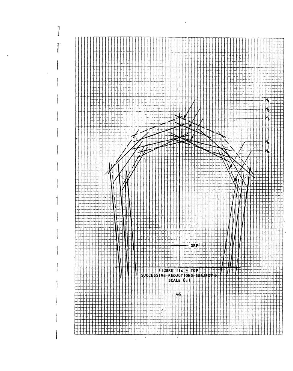
6 Figure LIST Of EIGURIS Page 1 Subject in Seated Po4tiqn 13 Sujec in Standijg'Pos4 op 14 3 Three Views of Pontng $OAyenqe 15 4a Donning Sequence Pr~fe o Sfjbjects M, B, 16 through C, and L Depicting Geometric qnfigurations through 7f for the Initial Unreptrtcted Puns 39 8 Calibration Curves for the TV, Pmeras 40 9 Ab~lut't Qhnn.Tim Vs, Volume Reltipe Donning TiMq Vp, ypltme 42 Ila Composites Of Donning Seqvenpe Profiles for 43 through Successive Rq4uctiqP 44P through 13c '51 iv
7 ADMINISTRATIVE INFORMATION Defense Purchase Request T-7716G of 15 May 1962 was assigned to the Air Crew Equipment Laboratory by the National Aeronautics and Space Administration, Manned Spacecraft Center, Houston 1, Texas. This study was conducted to determine the minimum volume and internal geometry of an envelope which will permit the donning and dbffin5 of the full pressure or space suit. An extension of 100 days was requested by NAVAIRENGCEN ietter XG-436:BHL:alc T-7716G/005-AEl3-14 (4080) of 30 October!962 and was granted by NASA on 12 February This report is in fulfillment of the subject NASA Purchase Request. This study was conducted in collaboration with Mr, Paul F. K~ehl, Technical Monitor, Life Systems Division, NASA (MSC). Ii I. v
8 ABSTRACT "Upon the request of the National Aeronautics and Space Administration (Manned Spacecraft Center), an investigation was conducted to determine the geometry and internal volume of the minimal envelope for donning the full pressure. suit. Specialized techniques were evolved to achieve a systematically variable, transparent, rigid encapsulation of the subject, as well as a parallax-free method for determining the gross threedimensional excursions of the suit/body silhouette from the nominal configuration. The precise limits of the donning geometry were determined using photoanalysis techniques. Subsequent to the determination of donning geometry, the internal volume was systematically reduced in-step-wise decrements along the spherical diameters from the seat reference point, and at each decrement, time. to don was recorded. Volumetric and geometric determinations were made on 5th and 95th percentile subjects. vi
9 INTRODUCTIO. C6nsiderations for crew comfort in-spade flights of.icreasing du ration turn quite naturally to the full pressure suit and present requirements for continuous wear of that garment, ait is by. no means certain what the cumulative stress effects of long term wear of-this garment are, nor at What point it becomev crucial to shift from a continuous wear garment~to a partial or intermittent wear suit. Contemplated for tho GEMINI mission is aconstant wear suit having access provisions for performance of excretory functions. 'Sinia the ' projected mission time for GEMINI may be as long as fourteen days,, the GEMINI program appears to be approaching the limiting conditions of habitibility for constant wear suits. At any rat4, the cabin volume of the GEMINI vehicle will not permit the removal of the entire suit in flight, in which case no further concessions to-crew comfort may be made,.desirable though they may be.... Wftbh respect to the APOLLO and subsequent vehicles, a modicum of space will likely be available for donning and doffing the suit.in flight, assuming the volumetric requirements for this purpose are not too great. In addition to the volumetric limitations, presumption of a "lshirtsleeve"l working regime implies an overall pressure protective capabiltity in the primary vessel to provide the astronauts With adequate time-regardless of the severity-of'the pressure vessel casualty-to don their,.-suits methodically;... Toward-these objectives, it becomes pertinent to establish the.limiting conditions of volume, geometry, and time for donning the full pressure suit. These data become crucial to the determination of Workplace layout, evaluation of developmental suits, and bioengineering of the life support systems. PRESENT STUDY This report presents the results of an investigation performed at the request of the National Aeronautics and Space Administration to determine the geometric configuration and associated minimal volume of an envelope which will ptrmit the donning of a given pressure suit garment. In effect, this means establishing the trade-off paradigm between degree of dimensional constriction and suit donning time, allowing operational considerations to be the final arbiter of what cons-titutes minimal. In pursuit of the study objectives,' there were many considerations which bore directly or indirectly on this prbhlem and which could have enormous influence on the results. Questions concerning the configuration of the pressure su.it which Omuld be worn, how much donning effort is permissible to be exacted from the astronaut, whether- the man will have'any assistance in the donning task, where the suit is located in the undonned configuration, what positional orientation the crewman wil-l be in. whev donning, what body size 4as the crewman, what, if any, concurremt'tasks the crewman Will be responsible for while donning-these and -many others have considerable bearing on. the resulting configuration of the donni'ng envelope. To many of these questions, answers were not available and,' consequently, certain "educated guesses" were made. These gisumptions'will be discussed in the body of this report. Needless to say, many of them may eventually prove to be in error and will necessitate reappraisal of these results for design purposes. 1
10 PART I - GEOMETBIC DETERMINATIONS Part I of this investigation involved the reasonably precise determination of the geometry despribed by the subject As he Apnne4 the suit under no constraints.* It was felt that once volymmetv p Tpictions were imposed on the subject, he would change his donning pattern in order to utilize the available space more effigiently, in which ;Ape *4 woid be impossible to designate a nominal donning geometry. Qnce the geometry ip determined, it is possible to determine the effects of systematic volume rv4dutions independent of changes in the donning geometry. Apparatus Figpres I and 2 are photograph qhwing 0 qubject in stages of the donning procesq.n the Appa~at~s w4ich has been dubbed the "Variform Capsule" or "V.C." for short. As can be seen, the Apparatus consists of a series of transparent acrykip.,stip panels mounted on crossbars in such fashion as to render a volume having 4 reasonably con~inuous surface, The mounting attachments of these panels inporpora.e four degreeq of freedom-4lateral, rotational, vertical, ano r ial-restlting in a qapplme having considerable variability in terms of geometry and volume, Once thp qapyile is adjusted to the desired cpnfigurattqn, the boundary surface ra **ain; xp and rigid. Inside the capsule is a simple, otraight~backe4 chair gxed t0 the fiqor. No attempt simulate was made any to type of acfeleration couch or other operational seat. was The intended seat only to provide A modicum of support with a minimum of restriction. To provide a relatively parallax-free observing and measuring technique, three closed.circiut television camera4 wev mounted outside of the V.C. and oriented in the three principal viqwtn8 Axoq-frnt, top, and side. The background for each of these views qonsifted of nine-foot IlPle4 square gxas" opalescent panels Aq lighteo with torg slimltne flourescent lights resulting in a silhouetted image on each televiqopn monitor, In setting up and calibrating the television cameras, compapion grids having a scale factor of 8:1 were used, The large grid of the pair was placed in either the median sagittal, frontal, or transverse plane of the body position within the capsule. The respective camera was then focused and aligqed to permit congruence between the small grid pf the pair, located over the mon*tqr face, and the image of the large grid which appeared on the CRT, Once ths process had been accomplished for each camera, the large grid wag vemoved frqm inside the capsule. When the subject entered the capsule, the effeqt was A scalqed-down picture of the subject's silhouette superimposed on a rectangulgr grid appearing at the subject's true median body planes, Fitted to the telegisipn monitors were Auricon cameras with T.V. synchronous shutters which provided g permanent Mo4$pn pi*ture record of the donning sequence for later analysis, Fipre 3 4hows a printed excerpt from the motion picture record, An attempt was ma4e to include situltaneous views of each monitor *Note No literature referenqes are cited in this report because none were found which had any bearing on the thz'eedimensional description of cumulative, whole-body motion while donning a garment within a systematically confined space. 2
11 on a single filmstrip. This, however, introduced a subsequent parallax error due to the location of the camera with respect to extreme portions of one or more of the monitors. The best rendition that could be achieved was a composite two-view filmstrip of either top/front or side/front views. This proved to be no problem in later analysis. Standard Navy MK IV full pressure suits were utilized in the study because of their ready availability in sufficient quantity at the ACEL. While it may be argued. that the investigations would have been more valid had more advanced type garments been employed, the MK IV suit is at least sufficiently akin to the MERCURY suit to permit a reasonable generalization of resul.tp to that garment. Essentially, any pressure suit which conforms to the configuration of the human body will, of necessity, correspond in large measure to the MK IV suit. Subjects Two groups of two subjects were utilized in this study-a 95th percentile group and a 5th percentile group-composed of officer and enlisted personnel at the Air Crew Equipment Laboratory. Table I shows the actual magnitudes of five critical morphological dimensions of the four subjec.ts. The percentile figures are based on an anthropometric survey of U.S. Navy pilots.* In addition to the body si4e criterion, subjec,tp were chosen on the basis of prior experience in the wear of the full pressure suit as well as the availability of a suit in the laboratory's inventory which would fit them. Most of the subjects used, even though. they had worn the quit many times, had had little or no occasion to don the suit unassisted. All subjects were, therefore, given several practice sessions prior to the recorded trials for the purpose of training them to a nominal plateau of donning proficiency. Procedure Subjects were first fitted to suits, adjusted in the same fashion as would be done were the subjects to be actually pressurized. These suits were then, reserved for the duration of the study to prevent any changes being made in the fit. Prior to each session, the suit closures were lubricated for ease of operation, all zippers were fully opened and all tiedowns (with the exception of the helmet and cross chest tiedowns) were placed loosely in their respective adjustment slides. The suit and associated gear were placed in the V.C. in the following pre-don configuration: basic suit folded compactly forward of the seat in such fashion as to expose the open entranceway; left boot and glove and right boot and glove placed together on respective sides of the seat on the deck; and helmet placed in the recess underneath the seat. Prior to donning, the subjects were attired in standard cotton two-piece long underwear with athletic socks. The configuration of the V.C. apparatus for the geometric. determinations was an arbitrary one based on informal observations of practice donning sessions. *Note - As can be seen, designation of subjects as aggregate 5th or 95th percentile is purely arbitrary. A true 5th or 95th percentile spbject is a theoretical fiction not found in the flesh. Our subjects could, in fact, more accurately be described as q'small" or "large.", 3
12 Trie objective was to constrain the subjects to a fixed location relative to the tv. cameras without imposing Any restrictions to the free manipulation of the body or the suit. Subjects were subsequently questioned as to the adequacy of the volume and their comments indicated no interference. The subject was placed in the V,C, and given instructions to begin donning on signal and proceed'as rapidly as possible short of making errors of haste. 'E-ach subject was also instructed that donning would be complete only when he felt that the integrity of the suit was adequate to the point where he would be willing to undergo immediate decompression4 He was told to give a "thumbs up" signal at'that point and the sequence would be at an end. Timing was accomplished by means of a s-andard stop-watch. While there were some variations between subjects and between sessions, the typical donning sequence was as follows: 1, Left leg placed in suit up to knee, leg zipper closed and left boot donned and zippered; 2, Right leg et. sem. 3. Subject stands and works suit up torso, left arm placed in sleeve, right arm placed in sleeve; 4. Surplus bladder gathered in gusset and neck ring pulled up and over the head; 5, Gusset zipper closed, entrance zipper closed, neck zippers and snaps secured; 6, Subject sits and cinches all tiedowns; 7. Helmet donned and neck ring engaged; 8. teft glove donned and zippered (Ss learned a helpful technique of starting the ipper before engaging the witr cuffs, thus making the one-handed manipulation of the glove easier), restraining straps adjusted; 9, Right glove et. seq,. The precedence of left over right in this sequence is no mere artifact of subjective preference; due to the peculiar construction of the suit, left over right was often the more efficient procedure. Donning time and movements for each subject were recorded either two or three times in the unrestricted condition (sufficient to get a base time and motion pictures for analysis). The results reflect a composite base time score and donning profile for each subject for all runs. RESULTS AND DISCUSSION Table II is a summary of time scores for each subject for each donning session in the unrestricted configuration. The mean scores, which reflect 4
13 considerable differences among subjects with respect to donning proficiency, were later used as baselines to determine the penalty exacted by a reduction in donning volume. Figures 4a through 7f are the resultant donning profiles. Each number represents a particular subject and each letter subscript designates a particular view as indicated. In deriving these profiles, the film records were projected onto an opaque surface with grid markings identical to. those on which the image of the subject had been superimposed on the monitor face. Using a framing projector, each film clip was processed frame by frame, and each excursion of the suit/body silhouette from the nominal position was traced onto the projected surface. The result was the cumulative space occupied'by the suit/body for the entire donning sequence, each view separately. All runs for a given subject were combined and the profiles are presented in composite. The figures are in a true 8:1 scale and actual dimensions to be utilized in the second half of the study were derived by measuring directly from the drawings. By combining the separate views oithogonally, the three-dimensional geometry of the donning erivelope may be recreate It will be noted that six separate profiles for each subject are presented -seated: front, side, and top; standing: front, side, and top. Standing and seated views were collated separately for the purpose of ascertaining and correcting for any gross changes in scale factor due to the shift in body position relative to the camera location during the donning process. As can be seen in Figure 8, the calibration curves for the cameras (a single camera was used alternately for top and side views), at a nominal lens distance of approximately 108" only slight changes in the scale factor result from 'fairly wide excursions from the median position. Nevertheless, correction factors were introduced to normalize the standing profiles to the established 8:1 ratio. Separate presentation of the standing-sitting profiles has the additional advantage of helping to account for how the donning space is "spent" in separate phases of the donning sequence. This information can be utilized to assist in evaluating future prototype suits for donning space requirements relative to the MK IV suit. One further aspect of the donning profiles should be noted. While it is helpful to know the precise shape of th# donning contours, the tortuous patterns produced are difficult, if not impossible to utilize. Seen as dotted lines on each profile, then, is a smoothed, and regularly shaped geometric form established on the basis of all subjects and all trials considered in toto. These smoothed contours are felt to be a reasonable approximation of the raw profiles and were used as the nominal geometric form for Part II of this investigation. PART I1 - VOLUMETRIC DETERMINATIONS The second part of this study was aimed at determining the trade-off between donning volume and time, holding geometric configuration constant. It was hypothesized that subjects could accommodate preliminary restrictions in donning volume in two ways: by utilizing the available space more efficiently, and by exerting greater effort in the process. The effect would be to maintain a level response time comparable to the unrestricted condition and, at some point in the dimcnution of donning volume, time would rapidly peak to a maximum followed by the subject's inability to complete the donning cycle. Within the limits of 5
14 available time and funds, an attempt was made to determine energy expenditure along with donning time. The measures employed, however, were too crude to be meaningful in this context. Patently, future studies of this kind should include a refined measure of work output. Apparatus The apparatus utilized in Part II was identical with that of Part I with the exclusion of photographic recording of the donning sequences.. Sub lects The same subjects were utilized with the exception of subject L, a 5th percentile subject, who was no longer available. At this stage of the investigation it was impracticable to obtain a replacement subject of the same qualifications. The results of this study phase are, thus, based on two 95th percentile and one 5th percentile subjects. It stems reasonable to assume that any volume adequate fora 95thpercentile subject will be adequate for a 5th percentile subject. Procedure The same experimental procedure was used in Part II insofar as suit preparation, pre-don configuration, donning sequence and completion criterion were concerned. In Part II, however, the V.C. apparatus had been reconfigured to conform to the unrestricted geometry established in Part I. Subsequent to each donning trial for a given subject, the V.C. was reduced in internal volume by approximately two inches along each diameter towards the seat reference point (a reference point located at the intersection of the seat back and the seat bottom midway between the sides). The volume was systematically reduced until the subject was completely retained in the sitting position with knees, head, and shoulders touching the plastic plates of the capsule while in the resting position. It was felt that, though there may have been a poasibililty of the subjects' successfully donning in a still smaller volume, further reduction was meaningless for practical design considerations. At this point the donning sessions were ended. It should be noted that the V.C. did not reach the starting configuration for the 5th percentile subject until after the 95th percentile subjects had gone through two reductions (their third trial). This maygbe seem more clearly in Figures 9 and 10. RESULTS AND DISCUSSION Table III presents the summarized results of Part II. The second column indicates which of the subjects participated in each reduction configuration (subjects M and B are 95th percentile subjects; subject C is 5th percrentile). The numeral in subscript by each subject's initial indicates which step reduction that run represents for the particular subject. Column Vt is the calculated internal volume of the capsule for that run. Ta is the absolute donning time for each subject and 6T is the increment in donning time over base time. Although no statistical analysis was attempted on this data involving so small a number of subjects, inspection of the trend tends to lend support to the original 6
15 'hypothesis. Figures 9 and 10 illustrate the data of Table III in -raphic form. As predicted, subjects were actually able to accommodate severe reductions in donning volume with little or no penalty in donning time. All subjects showed their greatest increase in donning time when the volume was decreased to between 25.9 and 28.6#3, regardless of percentile. Subject M showed an abnormally large increment in donning time between the unrestricted condition and the first volumetric condition. Ideally, no volumetric restriction should have occurred between these two conditions; i.e., the first volumetric con? figuration of'the V.C. was merely a reorientation of the panels to conform to the geometry described by the subject himself in PArt I of the study. The unexpected donning time increment exhibited by subject M is felt to be accountable to a change in suits which occurred at this point in the study and which was dug to a broken gusset zipper in the original suit. Subject M complained of excess bladder in the second suit during subsequent donning sessions. 'Nevertheless, it was the only suit available which would come close to fitting this subject. The increase in time which can be attributed to the ill-fitting suit is'approximately three minutes. If subject M's times are-all reduced by a three minute correction, his curves on Figures 9 and 10 very closely approximate tlise of his counterpart 95th percentile subject B. Composite plots of each view of the capsule conto.rs for each successive volumetric reduction are shown as Figures lla - 13c. Thesefigures are in a true 8:1 scale and actual dimensions may be derived by direct measurement from the plots. Oraphic comparisons of each volumetric reduction may be made view for view by inspections of the plots. As can be readily seen, each reduction contour does not conform entirely to the original geometry, even though every effort was made to keep geometry constant. This was due to the characteristics of the V.C. which made it difficult to achieve a curvilinear contour using flat plates, especially so when the volumes become quite small. Altogether, therewereeight volumetric configurations utilized in Part II; however, each subject participated in no more than five. This is attributable to the fact that some subjects, due to the size of certain body features, reached an end point in some or all dimensions earlier than others. As a consequence, some reduction configurations (c.f;, Columnl,Table III) will pertaintoonulynesubject, some to two, and some to all three (c.f., Column 2, Table III). The subscript by the subject's initial indicates which trial a given reduction is for that subject. This same convention is observed in identifying the successive reduction contours in Figures lla - 13c; i.e., the number of a given reduction profile on a particular figure refers to the subject's own sequence rather than the general sequence. The reader may refer back to Table III to ascertain the respective time factors and envelope volume for the reduction trial in question. The final datum point in each subject's curve (his final run) relates to a reduction of volume entirely to the sitting position. From Figures lla - 13c it can be seen that the contour of the envelope for this last run is considerably different from the preceding contours. The reason for this difference is that the sitting geometry, as determined in Part I, is notably different from the standing geometry. Further, once the subject reached a limit laterally, these dimensions remained fixed while the overhead alone was reduced to the sitting configuration. 7
16 CONCLUSIONS The geometry of the donning envelope is strikingly consistent from subject to subject for the MK IV full pressure suit. To the extent that the MK IV or a similar suit is concerned, the smooth contourl in Figures 4a - 7f could be utilized for human factors input to the design of workplace layout in vehicles where suit donning is a consideration. This, of course, assumes a rigid enclosure; were it otherwine, the geometry of the enclosure would be of lesser import. Should it be desirable to acquire small increments of space near the subject, but external to the donning envelope (for placement of discrete cortrols, instruments, etc.), designers may refer to the raw contours of Figures 4a - 7f to find common areas of exclusion. With respect to minimal volume, operational considerations must dictate a criterion, relative to time available, space available, and allowable energy expenditure. From this study, it appears that the best achievable donning time for the suit used (with unlimited volume) approaches 5 minutes, depending on the donner's proficiency, From the curves of Figures 9 and 10 it appears that an optimal donning volume would be between.31.5 and,36 cubic feet (distributed according to the established geometry). This represents a considerable saving in volume over the unrestricted condition with little or no penalty in donning time. This optimal volume, of course, fails to take into account the work output exacted by such a volumetric reduction. It was mentioned at the outset that this study was conducted with certain assumptions in mind. In may be well to list these so that, if eventually some are found in gross error, the results may be interpreted accordingly. i. Crewmen will be required to don the su:t unassisted; 2. Crewmen will be enveloped independently in a rigid enclosure; 3. Crewmen will have no concurrent responsibilities while donning; 4. As long as the subject can don within a reasonable period of time, no limit to work output is established; 5. The suit will be similar in donning characteristics to the Navy MK IV suft; 6, Crewmen will don from sit-stand orientatio (our data covers both sit-stand and sit only; however, if the donning takes place under zero gravity, the body orientation may be a moot point); 7. The undonned configuration of the suit will be arrayed on the deck as described in this study; associated portable life support equipment will be stowed external to the donning envelope; 8. The crewman will not be attached to the vehicle by biosensors, life support equipment, etc. (although to be maintained in the orientation of this study under zero-g conditions, some restraints will be required). 8
17 RECOMMENDATIONS Within the limits described above, the conclusions drawn from this investigation are felt to be sufficiently reliable for design purposes. It is recommended that certain problem areas be given further consideration and perhaps investigation before drawing definitively from these results. Depending upon how radical the departure will be of future suits from the MK IV con- 'figuratidn, these suits should be subjected to similar investigation to establishi the app icability of the MK IV results. Since overstressing the crewman in the suit donning task is a condition to be avoided, it is considered vital to investigate the effects of systematic reductions in the donning volume on-work output. It would then be possible to determine whether ortinot the subjects of this study were maintaining their donning time under severe restrictions in volume only through an extravagant and unacceptable expenditure of energy. A conglomerate area which should' receive additional attention is the location of the sudt in the undonned configuration and related problems of using structural assists to simplify the donning process as well as the restraints which will be required for donning under zero gravity. As a point of departure, one might consider location of the basic suit in a slide-top recess below the feet which would'provide out-of-the-way stowage for the garment while being readily available for donning. The recess would also provide additional donning volume for the crewman. The bootees of the suit could be mechanically or magnetically attached to the base of the stowage compartment so that once the crewman's feet were in place, he could release himself from his couch and continue donning, restrained from freely floating about the donning evvelope without interference with the remaihing donning sequence. Location of the gloves in a recess at elbow level would eliminate reaching; further, they could be attached in such fashion to aid in donning. The helmet, located in a recess overhead would be readily accessible. These design proposals are, of course, only a few of the many possibilities. They are mentioned merely as illustrative of the intimate relationship between suit stowage, donfi..tn gi and associated restraints. 9
18 N -4 oww cu rj V) a CY.-4 ' CC' C.J41 $4C j4i.,4 CA c e' C.) E 4c 10 41, H4Ia 0 (A pq r0 'o N4 z 0.0 Hr -,4 0.)00 -a HH CA, H 0-4 Wr -D LfrI f~ 0 c10
19 I TABLE II UJNRESTRICTED DONNING TIMES (MIN:SEC) Sulb. Session Mean th %ile 5th Zile M 7:28 7:17 7:00 7:15 B 5:41 5: :23 C 12:05 8:21 9:38 10:01 L. 10:48 8: :32
20 TABLE III RESULTS OF VOLUMETRIC DETERMINATIONS Donning Time (Min:Sec) R43Ut - Subject T- Absolute Time AT -Time Increase Cion Exposure Vt (ft 3 ) M B -C M B C 1 MIBI :39 6:03 3:24 : :41 6:00 3:26 :37 3 M 3 B 3 C :13 5:16 8:51 2:58 :07* 1:10* 4 M :28 3:13 5 B 4 C :30 12:08 3:07 2:07 6 M 5 B :54 8:13 7:39 2:50 7 C l?:.37 2:36 8 C :28 4:27 *Decrement in time from base 12

21 I [ I Ii Ii [I Ii L 'i 4 I.

22 ii [I Ii Ii Ii f 7 I,> 4.
-6-83")
23 PHOTO NO: CAN (L)-6-83 FIGURE 3
24 FOGURE 4a SITTONG FRONT SUBJECT M - 95%lLE SCALE 8:1 16
25 I FIGURE 4b SITTING SIDE SUBJECT M M 5ILE SCALE 8:1 17
26 FIGURE 4r. SITTING TOP SUBJECT M - 95%1ILE SCALE 8:1 18
27 I -FIGURE 4c SITTING TOP SUBJECT M - 95%1ILE I SCALE 8:1 1 18
28 FIUE4 STNIGFRN SUJC M-ML FIGURE 8.1d
29 FIGURE 4e STANDING SIDE SUBJECT M~ -5MILE SCALE 8:1
30 j FLGURE 4f STANDING TOP SUBJECT M4-5MILE SCALE 8:1 21
31 I FIGURE 5a SITTING FRONT SUBJECT 8-95%Ilk SCALE 8:1 22
32 FIGURE 5b SITTIIAG SIDE SUBJECT B - 95%ILE SCALE 8': 1 23
33 I FIGURE 5c SITTING: TOP SU BJECT ll - 95%1 LE I.SCA4E 8:t 24
34 FIUE5 I2 STNIG RN SIJC -9%L.. C L -:
35 FIGURE 5e STANDING SlIDE. SUBJECT B M5ILE SCALE.8: I 26
36 FIGURE 5f STANDING TOP SUBJECT 8-95%OLE SCALE 8:1 27
37 FIGURE 6a SITTING FRONT SUBJECT C - 5%ILE SCALE 8:1
38 FIGURE 6b SITTING SIDE SUBJECT C - 5%ILE SCALE 8:1 29
39 FIGURE 6c SITTIN4G TOP SUBJECT C - 5%ILE SCALE 8:1 30
40 FIGUiE 6d STANDING FRONT SUBJECT C - AMCL SCALE '8:1 31
41 F 0GU RE 6 e STANDING 'SIDE SUBJECT C - 5%ILE SCALE 8:1 32
42 FIGURE 6f STANDING TOP SUBJECT.C - 5%ILE SCALE 8:1. 33
43 7L FIGURE 7a SITTING FRONT SUBJECT L - 5%ILE SCALE 8:4 34~
44 FIGURE 7A SITTING FRONT SUBJECT L WLE SCALE 8:1 35
45 FIGURE 7c SOTTING TOP SUBJECT L. - WLE SCALE 8:1 1 36
46 FIGJRE 7d STANW-NG FRONT SUBJECT L -5%ILE SCALE 81 :37
47 I FIGURE 7e STANDING. SIDE SUBJECT L - 5%ILE SCALE,8:1 38
48 ijnog FOUE7 O SUJC -5,I SC L,

49 I ~~~ -.. A~ I LL
50 ... I I 1;..~; ~~1~~~*
~~~i I,")
51 .~ d (sainulw)~~~i I, IV*e.. ff/...

52 II o Run:. I ~~77 0 JI i 7 I. I1L f f III I I I I f I f ILi 4

53 I FI I-t-F H- i~rnlk~flui~ 7 ~ 7C SV ~Q 7EU 1 JE I
54 7A 47.
.Kt~ ~.. '.")
55 KT 1 ~~. ~ F 11:.7 ii~i R).Kt~ ~.. '...

56 TTT n Itt-1: J Tl 7 Ar I IT, a J , _1 4 4 UG E 12oo SIDE HS1 CT Ecr.-q'-,-j_- (11 1E I ULL 47

57 'i'Hi~~ ~.. I ~ ~ ~ ~ ~ t i- - -.K; 0I-

58 H I rl. I~ ~~~ J.~z~ 1:... r2-111 T

59 I :.. t. Id7~ M.- J50 I LL

60 I E TO' I Li J.:i LL LIL
 t - 4 W o4 0C m 0 w i 0. -4 41 410 r & 14-0 1 w 0-4 4 4 L40410~.0 cc114 v1 =04 41.l, C44S 'C 40 v 0S)0m c>lw r0 411LI.")
61 IE 40 c c c a1lv4 L C o a 0 L 04 1 U 4-0 )4 r-n4 Q--14 L.14C C 1 I '-41C41. * -I >4 L W C-4L1 '0nL U L w - 0.) c) 0 #1 L # w- LU~~L C4- a CL 0,4 m.c Q44 0.! 'D W 4 C 4 ) t - 4 W o4 0C m 0 w i r & w L40410~.0 cc114 v1 =04 41.l, C44S 'C 40 v 0S)0m c>lw r0 411LI. v 0O c c L4 0' ' L OcO 0 41 I t E' r4o L0 z-o 1 0 M u (a L 04V1* L 3 *0.W 1 w '0 0) 00- E0 10 -,0 0-2c4-.J ~ 0 L LCC 0 C 0 C.0)L xl CL."C 04 *.11 = 0.. W *)-144 LC - 0 u LC E 0 ~ ) It0 *0 c1 OS 8 o01c z 0 41 CX.2 Go. 41m L 41 0) -- C4 -I - 1 L 41-2 o0 1 C C4 CL X.S T41,44 ) 00 41). 44- OO4LW4CE I." 'I ct Go *, )-LI u- I W t - 4 4C ' m.' - ". 4~ >~ L0W > a1,l(40cl W0 'v c.twc C Ua. f '0--L- C u. 1 r. - or 103USv0-4 w :; 44.)-'C- v ( W L 418"04e 4 -I- xwl I 2E1 vc 0)41cu40= W W 0L a & 1 C.0-4-,- L" 'ZS - L. -4C 0-410E 4 1 C C a:.' S C O~ U.J 1,)L 4 C 0 L 44L r 1L. WE C -44L40.a a: W U).. ~- L'011 ol~ '..o.' ' 0 4'0, w44 4- L 3-)-' E44 ) 4 :0 0r. 414 J ' , ).04 I (E- lb *.e --C c, a ' OW.0- - N ) 41 c 4- C).L * z O -0 C0 4-- C 4 0 1,I -~ c W CZL m44-,' OC rm 4,'o OC w wj 41-0) w.044 MW j.w c -4.).0O04U - 00 r- w l-1'z. 1-0 C L0 U 1 "4 L CS 1.O-' > It,- C 0 O1 a 3-4E 0 0 WZ(O L4 44. C C W05 ' L 414'L.1411C44 I s IL 05 L 1 04 I' u w0 41 0% (t0 WU- ' C L1 r ac W-. 41 LC TLL 0-0 Z, 41-3c- - 4 LU.- c~44 *i WO L 1W. to a.41 S) 4 LU- 41r, Cfl.. 0 0e L:a W V 4> r * u - C30 Cd ' L L +' 41 O Ca 0' 0 04r 41 E0.O d e 041 I O.0 E1 A-. vi 41 -cj = C9.- LIc 0. 4 M C _., r C R' L,1,0n. -,. I C - Z--c' 0 * -Ln N l1,L' -. X4 IC ;c :. C n -... OS)t..a. 0 0: 4_ 0 W _ 0 L Z 0- (t w1 v 04 +,._ w w0- LL.4. - C 414 >0 d C)L L : 0 W- L.2~ _C 41a 4L 4'4U41L 14.) = M ( UU4.- 0 u, C ) a,~~4 r u44 1Z 0 030*', oj U.. I C5 4o 41 z4 0 U a' - c. L C' 1 *0 U 0 0 C 4 w = 4-w r= 41C414 LC 41= &=02. L, CC U L 41 L ut d1- c - 0I Ca 11 C,----1 L. 'a0-4 'a W1--04 mo U41. CO.' 144 L OLA C5 41>-L 1.00 L00LU6 cc1clol. C a CL 0 0of L& OS) U > (t0u' > 0.0 c' 0 0=1... 4L LU- 0.-j S en 0 C_ 41 0L- 4- =10 04 L 1 OS en Cc #j L U C.10r 0-, C -jc Ca C 0 XO c cm41-0 ) u0 M.C44 'LLI-m 54 SO; c -- 0 w414a C C L c ON O. w u w U 0 o 1 L0o 4-4.' L.1O.4' cc CD 41 Z LC- >0L 8 - OS1-0 Um 96UC 1 u- LI WOC41OLC4--' z(t a0"r.4 w ts L2 4 C1L.4 -L 0~~~~~~ 0 '- L CE l L a- L-4- I 0 C CO Q:. LIc 0 01 ) 0 r C 0 4.' l 1L. ) 2 0 a U Vi (t ~4'I LW ! -C 41 I L W Le C%1- ME 4 r 41 - LI L-.J a ~ 41 LI ~ Ln4 - WW MCL U M a3 t C%. WW4a W CL U_ a w o400- Lc0n COn c0144 W O '~.0. 4 W OI 1C &14. 0~ L 0'4. C c 1 0 C4 61J i410 L t W-4, 41 2 L0 0 14( ---M U.! OC L - 0 S.4S 1-4 ~ S'.-I 4-84 r W1. 4' w W 4 4C N C4 U - 4' A 41,' I W *41 U 041z.)4--C--a 4 il ) LO 1U 1 CI O.. * Q11 L t CD C C 0 t. 0.J0 a 81~ L 41 0, 4 & CC. (.. E WO- ).e ' L oo 01 W 41-4-)) I 0. UO CA U.IU 4 C _ Z40 CA 4-0 ~ 4 1 a040 IV L( 0 U *L W C- ~ 0 O 0 4 1' *L 04 L.4 4' (to v V u O -W U * -40. WO 4-, E CLLI Mt E-( 41- W W _. o.= 1 - a.0 CCW u&.04 W4 Wa -- A 14 )( C 0v W'.W C, 0- Z L (0 0 w A.4 1- L4L 41-0 C 4 =4 - LI40L0 4 WWOI 0L r 00 C 00 WO W WOLI. CL no 'oc)~ -. V= ~ U~ C- >I 20 21I4 0 1.I-C1 r 1-00 ci 4 (t. WO4114 L04 4.L C) 1-1 w. 04 WWO444 LU 41 ). 1 V= U0C I 41 )4.1 o:; -. C EU O 4 1-) ' L u m o L.2 cc L' = W L I 04- o 0 L' I L 1 a - 04' 0 - CY ~ v04 ~ 4 E) Z 4-0 C M4 en C4- U 4184-C 41-I ( -0 L..' CO ~4'M L C It CL C 41. '" CC.I4-V C '4W cc U - 4.-) 0.0 Lo "0.) ' w. -Co l.. 0 U L CO 414 C0 >, 4411 W 0 W=- LI~ CO 411 I 484 w~ O U L L.~8.* U-U O~.C L4 (E 1 0 C C1 x.4 c U0-04x 4 L 10 X4u % uj a-* 0 A cn S)4 1.0 L *. 0 ~0 1 cn. U4 1.)-114
THE COLLEGE OF AERONAUTICS CRANFIELD
 THE COLLEGE OF AERONAUTICS CRANFIELD AERODYNAMIC CHARACTERISTICS OF A 40 SWEPT BACK WING OF ASPECT RATIO 4.5 by P. S. BARNA NOTE NO. 65 MAY, 1957 CRANFIELD A preliminary report on the aerodynamic characteristics
Presented to the International Technical Rescue Symposium, November Abstract
 Presented to the International Technical Rescue Symposium, November 21 Presented by: Chuck Weber, PMI Quality Manager Abstract This paper presents the results of 162 individual drop tests performed at
Naval Postgraduate School, Operational Oceanography and Meteorology. Since inputs from UDAS are continuously used in projects at the Naval
 How Accurate are UDAS True Winds? Charles L Williams, LT USN September 5, 2006 Naval Postgraduate School, Operational Oceanography and Meteorology Abstract Since inputs from UDAS are continuously used
Wind Flow Validation Summary
 IBHS Research Center Validation of Wind Capabilities The Insurance Institute for Business & Home Safety (IBHS) Research Center full-scale test facility provides opportunities to simulate natural wind conditions
MoPac South: Impact on Cesar Chavez Street and the Downtown Network
 MoPac South: Impact on Cesar Chavez Street and the Downtown Network Prepared by: The University of Texas at Austin Center for Transportation Research Prepared for: Central Texas Regional Mobility Authority
A New Piston Gauge to Improve the Definition of High Gas Pressure and to Facilitate the Gas to Oil Transition in a Pressure Calibration Chain
 A New iston Gauge to Improve the Definition of High Gas ressure and to Facilitate the Gas to Oil Transition in a ressure Calibration Chain ierre Delajoud, Martin Girard DH Instruments, Inc. 4765 East Beautiful
Anti-g-Garment Development and Testing
 Anti-g-Garment Development and Testing 1) Anti-g-Garment. Introduction and Use in space flights. A g-suit, or anti-g suit, is a flight suit worn by pilots and astronauts who are subject to high levels
A Previously Unidentified Failure Mode for Ladder-Climbing Fall-Protection Systems
 Session No. 716 A Previously Unidentified Failure Mode for Ladder-Climbing Fall-Protection Systems Introduction Steve Arndt, Ph.D. Principal Engineer Exponent Failure Analysis Associates Chicago, Illinois
Space Simulation MARYLAND U N I V E R S I T Y O F. Space Simulation. ENAE 483/788D - Principles of Space Systems Design
 Focus is on human-in-the-loop operational simulations, not component sims (e.g., thermal vacuum chambers) Microgravity Planetary surfaces Specialty simulations A vision and a challenge... 1 2012 David
Report for Experiment #11 Testing Newton s Second Law On the Moon
 Report for Experiment #11 Testing Newton s Second Law On the Moon Neil Armstrong Lab partner: Buzz Aldrin TA: Michael Collins July 20th, 1969 Abstract In this experiment, we tested Newton s second law
23 RD INTERNATIONAL SYMPOSIUM ON BALLISTICS TARRAGONA, SPAIN APRIL 2007
 23 RD INTERNATIONAL SYMPOSIUM ON BALLISTICS TARRAGONA, SPAIN 16-20 APRIL 2007 AN INVESTIGATION INTO THE INTERRELATION BETWEEN THE INTERNAL AND EXTERNAL BALLISTICS OF FIRING A TP-T TANK AMMUNITION M. H.
Human Factors and Habitability
 Human Factors and Habitability Discussion of Midterm Required Crew Volumes Human Physiological Adaptation to 0G Workstation Design Restraint Design Ideal Cabin Layout Habitability in Partial Gravity Stowage
Volume-to-Capacity Estimation of Signalized Road Networks for Metropolitan Transportation Planning
 Volume-to-Capacity Estimation of Signalized Road Networks for Metropolitan Transportation Planning Hao Xu (Corresponding Author) Research Associate Department of Civil & Environmental Engineering Texas
Gas Gathering System Modeling The Pipeline Pressure Loss Match
 PETROLEUM SOCIETY CANADIAN INSTITUTE OF MINING, METALLURGY & PETROLEUM PAPER 2005-230 Gas Gathering System Modeling The Pipeline Pressure Loss Match R.G. MCNEIL, P.ENG. Fekete Associates Inc. D.R. LILLICO,
LOW PRESSURE EFFUSION OF GASES adapted by Luke Hanley and Mike Trenary
 ADH 1/7/014 LOW PRESSURE EFFUSION OF GASES adapted by Luke Hanley and Mike Trenary This experiment will introduce you to the kinetic properties of low-pressure gases. You will make observations on the
LYNNWOOD ROAD ARTERIAL STUDY The effect of intersection spacing on arterial operation
 LYNNWOOD ROAD ARTERIAL STUDY The effect of intersection spacing on arterial operation A J Joubert*, S L Burnett**, and T Ueckermann* *PWV Consortium, PO Box 1109, Sunninghill 2157 **Gautrans, Gauteng Department
Vibration-Free Joule-Thomson Cryocoolers for Distributed Microcooling
 Vibration-Free Joule-Thomson Cryocoolers for Distributed Microcooling W. Chen, M. Zagarola Creare Inc. Hanover, NH, USA ABSTRACT This paper reports on an innovative concept for a space-borne Joule-Thomson
STATIC AND DYNAMIC EVALUATION OF THE DRIVER SPEED PERCEPTION AND SELECTION PROCESS
 STATIC AND DYNAMIC EVALUATION OF THE DRIVER SPEED PERCEPTION AND SELECTION PROCESS David S. Hurwitz, Michael A. Knodler, Jr. University of Massachusetts Amherst Department of Civil & Environmental Engineering
Equation 1: F spring = kx. Where F is the force of the spring, k is the spring constant and x is the displacement of the spring. Equation 2: F = mg
 1 Introduction Relationship between Spring Constant and Length of Bungee Cord In this experiment, we aimed to model the behavior of the bungee cord that will be used in the Bungee Challenge. Specifically,
Evaluating the Influence of R3 Treatments on Fishing License Sales in Pennsylvania
 Evaluating the Influence of R3 Treatments on Fishing License Sales in Pennsylvania Prepared for the: Pennsylvania Fish and Boat Commission Produced by: PO Box 6435 Fernandina Beach, FL 32035 Tel (904)
Operational Ranking of Intersections: A Novel Prioritization Methodology
 Operational Ranking of Intersections: A Novel Prioritization Methodology Reza Omrani, Ph.D. Transportation Engineer CIMA+ 3027 Harvester Road, Suite 400 Burlington, ON L7N 3G7 Reza.Omrani@cima.ca Pedram
RESEARCH MEMORANDUM. WASHINGTON December 3, AERODYNl$MIC CHARACTERISTICS OF A MODEL? OF AN ESCAPE ...,
 .". -.%. ;& RESEARCH MEMORANDUM AERODYNl$MIC CHARACTERISTICS OF A MODEL? OF AN ESCAPE 1 \ < :. By John G. Presnell, Jr. w'..., '.., 3... This material contains information affecting the National Bfense
VEHICULAR TRAFFIC PROGRESSION TIME-SPACE PLOT PROGRAM
 VEHICULAR TRAFFIC PROGRESSION TIME-SPACE PLOT PROGRAM Texas Highway Department Division of Automation Revised 1973 This program is a modified version of a program written by IBM. The original program made
Post impact trajectory of vehicles at rural intersections
 Post impact trajectory of vehicles at rural intersections Doecke SD., Woolley JE. and Mackenzie JR. Centre for Automotive Safety Research Abstract This report describes the path of vehicles after a collision
TESTING APPLICATION STANDARD (TAS)
") TESTING APPLICATION STANDARD (TAS) No. 00(A)-9 TEST PROCEDURE FOR WIND AND WIND DRIVEN RAIN RESISTANCE AND/OR INCREASED WINDSPEED RESISTANCE OF SOFFIT VENTILATION STRIP AND CONTINUOUS OR INTERMITTENT VENTILATION
TESTING APPLICATION STANDARD (TAS) No. 00(A)-9 TEST PROCEDURE FOR WIND AND WIND DRIVEN RAIN RESISTANCE AND/OR INCREASED WINDSPEED RESISTANCE OF SOFFIT VENTILATION STRIP AND CONTINUOUS OR INTERMITTENT VENTILATION
Technical Note. Determining the surface tension of liquids by measurements on pendant drops
 Technical Note Pendant Drop Measurements Technical note: TN316e Industry section: all Author: FT, TW Date: 12/2010 Method: Drop Shape Analyzer DSA100 Keywords: Methods, surface tension, interfacial tension,
OP CHECKLIST FOR 1D CONSOLIDATION LABORATORY TEST
 Page 1 of 5 WORK INSTRUCTIONS FOR ENGINEERS NHB Compiled by : LSS Checked by : GSS Approved by : OP-3-31. CHECKLIST FOR 1D CONSOLIDATION LABORATORY TEST Page 2 of 5 31.0 CHECKLIST ITEMS *(refer to respective
UNITED STATES MARINE CORPS WEAPONS TRAINING BATTALION MARINE CORPS COMBAT DEVELOPMENT COMMAND QUANTICO, VIRGINIA INSTRUCTOR GUIDE
 UNITED STATES MARINE CORPS WEAPONS TRAINING BATTALION MARINE CORPS COMBAT DEVELOPMENT COMMAND QUANTICO, VIRGINIA 22134-5040 INSTRUCTOR GUIDE ZERO A RIFLE COMBAT OPTIC (RCO) TO A SERVICE RIFLE 0300-M16-1005
Autodesk Moldflow Communicator Process settings
 Autodesk Moldflow Communicator 212 Process settings Revision 1, 3 March 211. Contents Chapter 1 Process settings....................................... 1 Profiles.................................................
EE 364B: Wind Farm Layout Optimization via Sequential Convex Programming
 EE 364B: Wind Farm Layout Optimization via Sequential Convex Programming Jinkyoo Park 1 Introduction In a wind farm, the wakes formed by upstream wind turbines decrease the power outputs of downstream
6. EXPERIMENTAL METHOD. A primary result of the current research effort is the design of an experimental
 6. EXPERIMENTAL METHOD 6.1 Introduction A primary result of the current research effort is the design of an experimental setup that can simulate the interaction of a windmill with a vortex wake and record
Chapter 5: Methods and Philosophy of Statistical Process Control
 Chapter 5: Methods and Philosophy of Statistical Process Control Learning Outcomes After careful study of this chapter You should be able to: Understand chance and assignable causes of variation, Explain
An Analysis of the Travel Conditions on the U. S. 52 Bypass. Bypass in Lafayette, Indiana.
 An Analysis of the Travel Conditions on the U. S. 52 Bypass in Lafayette, Indiana T. B. T readway Research Assistant J. C. O ppenlander Research Engineer Joint Highway Research Project Purdue University
Examples of Carter Corrected DBDB-V Applied to Acoustic Propagation Modeling
 Naval Research Laboratory Stennis Space Center, MS 39529-5004 NRL/MR/7182--08-9100 Examples of Carter Corrected DBDB-V Applied to Acoustic Propagation Modeling J. Paquin Fabre Acoustic Simulation, Measurements,
Economic and Social Council
 United Nations Economic and Social Council Distr.: General 27 February 2015 Original: English Economic Commission for Europe Inland Transport Committee World Forum for Harmonization of Vehicle Regulations
Wind tunnel effects on wingtip vortices
 48th AIAA Aerospace Sciences Meeting Including the New Horizons Forum and Aerospace Exposition 4-7 January 2010, Orlando, Florida AIAA 2010-325 Wind tunnel effects on wingtip vortices Xin Huang 1, Hirofumi
Course Firefighter I. Unit II Safety and Orientation
 Course Firefighter I Unit II Safety and Orientation Essential Question Why is proficiency donning and doffing SCBA important for firefighters? TEKS 130.299(c) (2)(C), (10)(B), (11)(A)(C)(E), (14)(A)(B)
SUBPART C - STRUCTURE
 SUBPART C - STRUCTURE GENERAL CS 23.301 Loads (a) Strength requirements are specified in terms of limit loads (the maximum loads to be expected in service) and ultimate loads (limit loads multiplied by
ZIPWAKE DYNAMIC TRIM CONTROL SYSTEM OUTLINE OF OPERATING PRINCIPLES BEHIND THE AUTOMATIC MOTION CONTROL FEATURES
 ZIPWAKE DYNAMIC TRIM CONTROL SYSTEM OUTLINE OF OPERATING PRINCIPLES BEHIND THE AUTOMATIC MOTION CONTROL FEATURES TABLE OF CONTENTS 1 INTRODUCTION 3 2 SYSTEM COMPONENTS 3 3 PITCH AND ROLL ANGLES 4 4 AUTOMATIC
DERIVATION OF A SIGNAL TIMING SCHEME FOR AN EXTERNALLY SIGNALIZED ROUNDABOUT
 DERIVATION OF A SIGNAL TIMING SCHEME FOR AN EXTERNALLY SIGNALIZED ROUNDABOUT Paper Presented at the Annual Sessions of the Institute of Engineers, Sri Lanka Dr. Amal S. Kumarage, Senior Lecturer Dr. J.M.S.J.
Launch Vehicle Performance Estimation:
 Launch Vehicle Performance Estimation: John Schilling john.schilling@alumni.usc.edu (661) 718-0955 3 December 2009 Precise determination of launch vehicle performance typically requires the use of three-
Space Simulation MARYLAND U N I V E R S I T Y O F. Space Simulation. ENAE 483/788D - Principles of Space Systems Design
 Lecture #27 December 4, 2014 Focus of this lecture is on human-in-the-loop operational simulations, not component sims (e.g., thermal vacuum chambers) Microgravity Planetary surfaces Specialty simulations
POWER Quantifying Correction Curve Uncertainty Through Empirical Methods
 Proceedings of the ASME 2014 Power Conference POWER2014 July 28-31, 2014, Baltimore, Maryland, USA POWER2014-32187 Quantifying Correction Curve Uncertainty Through Empirical Methods ABSTRACT Christopher
THE C.A.R. SYSTEM OF GUNFIGHTING
 THE C.A.R. SYSTEM OF GUNFIGHTING A. It is a gun fighting technique, not a range application. - It is a strong, stable, and flexible platform for action. - It allows quick target acquisition and rapid fire
Effect of airflow direction on human perception of draught
 Effect of airflow direction on human perception of draught J. Toftum, G. Zhou, A. Melikov Laboratory of Indoor Environment and Energy Department of Energy Engineering Technical University of Denmark Abstract
UNITED STATES MARINE CORPS WEAPONS TRAINING BATTALION MARINE CORPS COMBAT DEVELOPMENT COMMAND QUANTICO, VIRGINIA
 UNITED STATES MARINE CORPS WEAPONS TRAINING BATTALION MARINE CORPS COMBAT DEVELOPMENT COMMAND QUANTICO, VIRGINIA 22134-5040 DETAILED INSTRUCTOR GUIDE LESSON TITLE FUNDAMENTALS OF RIFLE MARKSMANSHIP COURSE
Introduction to Habitability
 Introduction to Habitability Required Crew Volumes! Human Physiological Adaptation to 0G! Workstation Design! Restraint Design! Ideal Cabin Layout! Habitability in Partial Gravity! Stowage! Various Examples
SECTION 2 HYDROLOGY AND FLOW REGIMES
 SECTION 2 HYDROLOGY AND FLOW REGIMES In this section historical streamflow data from permanent USGS gaging stations will be presented and discussed to document long-term flow regime trends within the Cache-Bayou
Assembly and measurements of a mechanical prototype of the BIS MDT chamber
 ATLAS Internal Note MUON NO 243 9 June 1998 Assembly and measurements of a mechanical prototype of the BIS MDT chamber K. Ekonomou Physics Department, Aristotle University of Thessaloniki, Thessaloniki,
Compatibility: Your Connection
 Compatibility: Your Connection Kevin Denis Gravitec Systems, Inc., 21291 Urdahl Road NW, Poulsbo, WA, 98370 USA Abstract. A life or death point of failure for any fall protection and rescue system is the
A Research on the Airflow Efficiency Analysis according to the Variation of the Geometry Tolerance of the Sirocco Fan Cut-off for Air Purifier
 A Research on the Airflow Efficiency Analysis according to the Variation of the Geometry Tolerance of the Sirocco Fan Cut-off for Air Purifier Jeon-gi Lee*, Choul-jun Choi*, Nam-su Kwak*, Su-sang Park*
CFD AND EXPERIMENTAL STUDY OF AERODYNAMIC DEGRADATION OF ICED AIRFOILS
 Colloquium FLUID DYNAMICS 2008 Institute of Thermomechanics AS CR, v.v.i., Prague, October 22-24, 2008 p.1 CFD AND EXPERIMENTAL STUDY OF AERODYNAMIC DEGRADATION OF ICED AIRFOILS Vladimír Horák 1, Dalibor
Operational Comparison of Transit Signal Priority Strategies
 Operational Comparison of Transit Signal Priority Strategies Revision Submitted on: November, 0 Author: Adriana Rodriguez, E.I Assistant Engineer Parsons Brinckerhoff 0 South Orange Avenue, Suite 00 Orlando,
b
 Empirically Derived Breaking Strengths for Basket Hitches and Wrap Three Pull Two Webbing Anchors Thomas Evans a and Aaron Stavens b a Montana State University, Department of Earth Sciences, PO Box 173480,
Novel empirical correlations for estimation of bubble point pressure, saturated viscosity and gas solubility of crude oils
 86 Pet.Sci.(29)6:86-9 DOI 1.17/s12182-9-16-x Novel empirical correlations for estimation of bubble point pressure, saturated viscosity and gas solubility of crude oils Ehsan Khamehchi 1, Fariborz Rashidi
JAR-23 Normal, Utility, Aerobatic, and Commuter Category Aeroplanes \ Issued 11 March 1994 \ Section 1- Requirements \ Subpart C - Structure \ General
 JAR 23.301 Loads \ JAR 23.301 Loads (a) Strength requirements are specified in terms of limit loads (the maximum loads to be expected in service) and ultimate loads (limit loads multiplied by prescribed
OBJECTIVE 6: FIELD RADIOLOGICAL MONITORING - AMBIENT RADIATION MONITORING
 OBJECTIVE 6: FIELD RADIOLOGICAL MONITORING - AMBIENT RADIATION MONITORING OBJECTIVE Demonstrate the appropriate use of equipment and procedures for determining field radiation measurements. INTENT This
Development of TEU Type Mega Container Carrier
 Development of 8 700 TEU Type Mega Container Carrier SAKAGUCHI Katsunori : P. E. Jp, Manager, Ship & Offshore Basic Design Department, IHI Marine United Inc. TOYODA Masanobu : P. E, Jp, Ship & Offshore
A Conceptual Approach for Using the UCF Driving Simulator as a Test Bed for High Risk Locations
 A Conceptual Approach for Using the UCF Driving Simulator as a Test Bed for High Risk Locations S. Chundi, M. Abdel-Aty, E. Radwan, H. Klee and E. Birriel Center for Advanced Transportation Simulation
Developments in Longwall Ventilation
 7 Developments in Longwall Ventilation Jiirgen F. Brune, Joseph P. Aman, and Mike Kotch CONSOL Inc., 18 Washington Road, Pittburgh, P A 15241 ABSTRACT Rapid development in longwall mining technology has
b
 Empirically Derived Breaking Strengths for Basket Hitches and Wrap Three Pull Two Webbing Anchors Thomas Evans a and Aaron Stavens b a Montana State University, Department of Earth Sciences, PO Box 173480,
LOW PRESSURE EFFUSION OF GASES revised by Igor Bolotin 03/05/12
 LOW PRESSURE EFFUSION OF GASES revised by Igor Bolotin 03/05/ This experiment will introduce you to the kinetic properties of low-pressure gases. You will make observations on the rates with which selected
I.CHEM.E. SYMPOSIUM SERIES NO. 97 BUOYANCY-DRIVEN NATURAL VENTILATION OP ENCLOSED SPACES
 BUOYANCY-DRIVEN NATURAL VENTILATION OP ENCLOSED SPACES M. R. Marshall* and P. L. Stewart-Darling* A simple mathematical model for the buoyancy driven ventilation of an enclosed space, using a two-pipe
ENHANCED PARKWAY STUDY: PHASE 2 CONTINUOUS FLOW INTERSECTIONS. Final Report
 Preparedby: ENHANCED PARKWAY STUDY: PHASE 2 CONTINUOUS FLOW INTERSECTIONS Final Report Prepared for Maricopa County Department of Transportation Prepared by TABLE OF CONTENTS Page EXECUTIVE SUMMARY ES-1
V393.R46. NalupwL UNITED STATES EXPERIMENTAL MODEL BASIN NAVY YARD, WASHINGTON, D.C. BILGE KEEL CAVITATION J. G. THEWS SEPTEMBER REPORT NO.
 V393.R46 NalupwL 3 9080 02753 9680 UNITED STATES EXPERIMENTAL MODEL BASIN NAVY YARD, WASHINGTON, D.C. BILGE KEEL CAVITATION BY J. G. THEWS SEPTEMBER 1933 REPORT NO. 371 MWIF- _ BILGE KEEL CAVITATION By
Is lung capacity affected by smoking, sport, height or gender. Table of contents
 Sample project This Maths Studies project has been graded by a moderator. As you read through it, you will see comments from the moderator in boxes like this: At the end of the sample project is a summary
Development of Low Volume Shape Memory Alloy Variable Ballast System for AUV Use
 Development of Low Volume Shape Memory Alloy Variable Ballast System for AUV Use Dr. Graeme J Rae Ocean Engineering Program Division of Marine and Environmental Systems Florida Institute of Technology
Mechanical Stabilisation for Permanent Roads
 Mechanical Stabilisation for Permanent Roads Tim Oliver VP Global Applications Technology Tensar International toliver@tensar.co.uk Effect of geogrid on particle movement SmartRock Effect of geogrid on
Investigation of Suction Process of Scroll Compressors
 Purdue University Purdue e-pubs International Compressor Engineering Conference School of Mechanical Engineering 2006 Investigation of Suction Process of Scroll Compressors Michael M. Cui Trane Jack Sauls
OBJECTIVE 22: EMERGENCY WORKERS, EQUIPMENT, AND VEHICLES - MONITORING AND DECONTAMINATION
 OBJECTIVE Demonstrate the adequacy of procedures for the monitoring and decontamination of emergency workers, equipment, and vehicles. INTENT This objective is derived from NUREG-0654 which provides that
Digiquartz Water-Balanced Pressure Sensors for AUV, ROV, and other Moving Underwater Applications
 Digiquartz Water-Balanced Pressure Sensors for AUV, ROV, and other Moving Underwater Applications Dr. Theo Schaad Principal Scientist Paroscientific, Inc. 2002 Paroscientific, Inc. Page 1 of 6 Digiquartz
EUROPEAN NEW CAR ASSESSMENT PROGRAMME (Euro NCAP) SLED TEST PROCEDURE FOR ASSESSING KNEE IMPACT AREAS
 SLED TEST PROCEDURE FOR ASSESSING KNEE IMPACT AREAS") www.euroncap.com EUROPEAN NEW CAR ASSESSMENT PROGRAMME (Euro NCAP) SLED TEST PROCEDURE FOR ASSESSING KNEE IMPACT AREAS Version 1.0a December 2004 Sled Test Procedure for Assessing Knee Impact Areas (V1.0a)
www.euroncap.com EUROPEAN NEW CAR ASSESSMENT PROGRAMME (Euro NCAP) SLED TEST PROCEDURE FOR ASSESSING KNEE IMPACT AREAS Version 1.0a December 2004 Sled Test Procedure for Assessing Knee Impact Areas (V1.0a)
HUMAN FACTORS PERFORMANCE OF A PROTOTYPE FIREFIGHTER SUIT WITH DEPLOYABLE CBRN FEATURES
 HUMAN FACTORS PERFORMANCE OF A PROTOTYPE FIREFIGHTER SUIT WITH DEPLOYABLE CBRN FEATURES Barker, R.L., Deaton, A.S., and Liston, G.C. Center for Research on Textile Protection and Comfort North Carolina
Development of a High Pressure, Oil Free, Rolling Piston Compressor
 Purdue University Purdue e-pubs International Compressor Engineering Conference School of Mechanical Engineering 1994 Development of a High Pressure, Oil Free, Rolling Piston Compressor S. J. Delmotte
VariSource High Dose Rate Afterloader Procedures. For Performing Breast Brachytherapy with. The SAVI TM Applicator
 VariSource High Dose Rate Afterloader Procedures For Performing Breast Brachytherapy with The SAVI TM Applicator Contents I. CT Evaluation (~1 week prior to insertion) II. SAVI Applicator Implantation
EFFECTIVE DESIGN OF CONVERTER HOODS. 111 Ferguson Ct. Suite 103 Irving, Texas U.S.A. 400 Carlingview Dr. Toronto, ON M9W 5X9 Canada.
 EFFECTIVE DESIGN OF CONVERTER HOODS Paykan Safe 1, Sam Matson 1, and John Deakin 2 1 Gas Cleaning Technologies 111 Ferguson Ct. Suite 103 Irving, Texas 75062 U.S.A. 2 H.G. Engineering, Ltd. 400 Carlingview
Lifecycle Performance of Escape Systems
 Lifecycle Performance of Escape Systems A look at laboratory vs field conditioning of aramid fiber based escape systems. By James Hunter, Cedric Smith, Ole Kils and Tyler Mayer for ITRS 2018 1.1 Introduction
Paper 2.2. Operation of Ultrasonic Flow Meters at Conditions Different Than Their Calibration
 Paper 2.2 Operation of Ultrasonic Flow Meters at Conditions Different Than Their Calibration Mr William Freund, Daniel Measurement and Control Mr Klaus Zanker, Daniel Measurement and Control Mr Dale Goodson,
INTERACTION BETWEEN WIND-DRIVEN AND BUOYANCY-DRIVEN NATURAL VENTILATION Bo Wang, Foster and Partners, London, UK
 INTERACTION BETWEEN WIND-DRIVEN AND BUOYANCY-DRIVEN NATURAL VENTILATION Bo Wang, Foster and Partners, London, UK ABSTRACT Ventilation stacks are becoming increasingly common in the design of naturally
Defining Purpose and Need
 Advanced Design Flexibility Pilot Workshop Session 4 Jack Broz, PE, HR Green May 5-6, 2010 Defining Purpose and Need In your agency s project development process, when do design engineers typically get
Marine Corps Physical Fitness Charts
 See More About: marine corps physical fitness test marine physical fitness Marine Corps Physical Fitness Charts Females Share Print Every Marine must be physically fit, regardless of age, grade, or duty
MANUFACTURE OF SUBSTRUCTURE BY AUTOMATED FIBER PLACEMENT
 MANUFACTURE OF SUBSTRUCTURE BY AUTOMATED FIBER PLACEMENT Trevor S. Angell Spirit AeroSystems 3365 S. Oliver St. Wichita, KS 67278 Todd Rudberg Electroimpact 4413 Chennault Beach Rd. Mukilteo, WA 98275
UNITED STATES MARINE CORPS WEAPONS TRAINING BATTALION MARINE CORPS COMBAT DEVELOPMENT COMMAND QUANTICO, VIRGINIA
 UNITED STATES MARINE CORPS WEAPONS TRAINING BATTALION MARINE CORPS COMBAT DEVELOPMENT COMMAND QUANTICO, VIRGINIA 22134-5040 DETAILED INSTRUCTOR GUIDE LESSON TITLE RIFLE ZEROING COURSE TITLE DIVISION MATCH
Development of Large Capacity CO2 Scroll Compressor
 Purdue University Purdue e-pubs International Compressor Engineering Conference School of Mechanical Engineering 2008 Development of Large Capacity CO2 Scroll Compressor Kenji Yano Mitsubishi Electric
SOLAR 93 THE 1993 AMERICAN SOLAR ENERGY SOCIETY ANNUAL CONFERENCE. Washington, DC April 22028,1993. Editors: S. M. Burley M. E.
 SOLAR 93 THE 1993 AMERICAN SOLAR ENERGY SOCIETY ANNUAL CONFERENCE Washington, DC April 22028,1993 Editors: S. M. Burley M. E. Arden American Solar Energy Society U.S. Section of the International Solar
(12) Patent Application Publication (10) Pub. No.: US 2011/ A1
 Patent Application Publication (10) Pub. No.: US 2011/ A1") US 2011 0082015A1 (19) United States (12) Patent Application Publication (10) Pub. No.: US 2011/0082015 A1 Dreissigacker et al. (43) Pub. Date: Apr. 7, 2011 (54) EXERCISING Publication Classification (51)
US 2011 0082015A1 (19) United States (12) Patent Application Publication (10) Pub. No.: US 2011/0082015 A1 Dreissigacker et al. (43) Pub. Date: Apr. 7, 2011 (54) EXERCISING Publication Classification (51)
Analysis of Traditional Yaw Measurements
 Analysis of Traditional Yaw Measurements Curiosity is the very basis of education and if you tell me that curiosity killed the cat, I say only the cat died nobly. Arnold Edinborough Limitations of Post-
Road Data Input System using Digital Map in Roadtraffic
 Data Input System using Digital Map in traffic Simulation Namekawa,M 1., N.Aoyagi 2, Y.Ueda 2 and A.Satoh 2 1 College of Management and Economics, Kaetsu University, Tokyo, JAPAN 2 Faculty of Engineering,
US NAVY DIVING PROGRAM: DIVING TO 300 FT DEPTHS USING SURFACE-SUPPLIED AND SATURATION FLY-AWAY DIVING SYSTEMS. Introduction
 US NAVY DIVING PROGRAM: DIVING TO 300 FT DEPTHS USING SURFACE-SUPPLIED AND SATURATION FLY-AWAY DIVING SYSTEMS James R. Wilkins Director of Ocean Engineering, Supervisor of Salvage and Diving Naval Sea
Figure 1 Schematic of opposing air bearing concept
 Theoretical Analysis of Opposing Air Bearing Concept This concept utilizes air bearings to constrain five degrees of freedom of the optic as shown in the figure below. Three pairs of inherently compensated
Results and Discussion for Steady Measurements
 Chapter 5 Results and Discussion for Steady Measurements 5.1 Steady Skin-Friction Measurements 5.1.1 Data Acquisition and Reduction A Labview software program was developed for the acquisition of the steady
MIL-STD-883G METHOD
 STEADY-STATE LIFE 1. PURPOSE. The steady-state life test is performed for the purpose of demonstrating the quality or reliability of devices subjected to the specified conditions over an extended time
An Analysis of Reducing Pedestrian-Walking-Speed Impacts on Intersection Traffic MOEs
 An Analysis of Reducing Pedestrian-Walking-Speed Impacts on Intersection Traffic MOEs A Thesis Proposal By XIAOHAN LI Submitted to the Office of Graduate Studies of Texas A&M University In partial fulfillment
Lab Report Outline the Bones of the Story
 Lab Report Outline the Bones of the Story In this course, you are asked to write only the outline of a lab report. A good lab report provides a complete record of your experiment, and even in outline form
CHAPTER 2G. PREFERENTIAL AND MANAGED LANE SIGNS
 2011 Edition - Revision 2 Page 275 Section 2G.01 Scope CHAPTER 2G. PREFERENTIAL AND MANAGED LANE SIGNS 01 Preferential lanes are lanes designated for special traffic uses such as high-occupancy vehicles
Drilling Efficiency Utilizing Coriolis Flow Technology
 Session 12: Drilling Efficiency Utilizing Coriolis Flow Technology Clement Cabanayan Emerson Process Management Abstract Continuous, accurate and reliable measurement of drilling fluid volumes and densities
Cover Page for Lab Report Group Portion. Pump Performance
 Cover Page for Lab Report Group Portion Pump Performance Prepared by Professor J. M. Cimbala, Penn State University Latest revision: 02 March 2012 Name 1: Name 2: Name 3: [Name 4: ] Date: Section number:
ANALYZING THE SHIP DISPOSAL OPTIONS
 Chapter Six ANALYZING THE SHIP DISPOSAL OPTIONS Chapters Two through Five examined the option of long-term storage and the three ship-disposal options: domestic recycling, overseas recycling, and reefing.
AIAA Brush Seal Performance Evaluation. P. F. Crudgington Cross Manufacturing Co. Ltd. Devizes, ENGLAND
 AIAA 98-3172 Brush Seal Performance Evaluation P. F. Crudgington Cross Manufacturing Co. Ltd. Devizes, ENGLAND BRUSH SEAL PERFORMANCE EVALUATION AIAA-98-3172 P. F. Crudgington Cross Manufacturing Co. Ltd
Final Report: Measurements of Pile Driving Noise from Control Piles and Noise-Reduced Piles at the Vashon Island Ferry Dock
 Final Report: Measurements of Pile Driving Noise from Control Piles and Noise-Reduced Piles at the Vashon Island Ferry Dock By Peter H. Dahl, Jim Laughlin, and David R. Dall Osto Executive Summary Underwater