Instruction Manual. PE-25/32/37 Tapping Machines. POLYTAPP Valves
|
|
|
- Vernon Henry
- 5 years ago
- Views:
Transcription

1 Instruction Manual PE-25/32/37 Tapping Machines & POLYTAPP Valves
2 Nov 2016, Revision 2 Document Number M.T. Deason Company, Inc. PO Box Birmingham, AL Phone: Fax: Page 1 of 17

3 INTRODUCTION TO TAPPING MACHINE & POLYTAPP VALVE These instructions are designed to provide the operator with factory recommended procedures for safe and effective use of MTD Tapping Machines. This equipment is designed to tap through the MTD POLYTAPP Valve System. Under no circumstances should you exceed factory recommended specifications. Utilize all safety precautions and procedures to ensure operator safety. MTD recommends that the operator has read and is completely familiar with this entire manual before operating any Tapping Machine. MTD recommends that the operator be trained in accordance with this instruction manual and perform test taps under pressure prior to field operations. Prior to use please contact M. T. Deason Company with any questions or concerns. POLYTAPP VALVE TAPPING MACHINE Page 2 of 17
4 CAUTION: Do not proceed with any tapping operation which will depart from the procedures described in this instruction manual. Any such departure could result in personal injury or property damage. Any alteration to any tapping machine nullifies and cancels all warranties. Contact MTD for replacement parts or maintenance. Any alteration any MTD Tapping Machine, adapter or accessory may result in personal injury or equipment malfunction. MTD Tapping Machines are designed to make hot taps on polyethylene pipe as part of the MTD POLYTAPP system. Any universal processor equipped with 4.7mm fusion terminals may be utilized for fusing components of the MTD POLYTAPP System. All Tapping Machines are equipped with fast feed for advancement of body tube and slow feed for cutting. Tapping Machine Specifications PE 25 PE 32 PE 37 Part Number TRI1080 TRI1082 TRI Max Operating Pressure 250psi 250psi 250psi Max Operating 115 F 115 F 115 F Temperature Tap Sizes * 2, 4 2, 4, 6 2, 4, 6, 8 Main Sizes 2 and above 2 and above 2 and above Feed Rates Fast (Feed Tube) Slow (Boring Bar) 1.00 per 360 Turn 0.04 per 360 Turn 1.00 per 360 Turn 0.04 per 360 Turn Maximum Travel Machine Weight 38lbs 43lbs 48lbs Length (Extended) * Tap sizes listed are for taps made through POLYTAPP valves per 360 Turn 0.04 per 360 Turn Page 3 of 17
5 SAFETY Operator must be familiar with location and function of all safety features included with tapping machine and related equipment. WARNINGS and CAUTIONS The purpose of WARNINGS and CAUTIONS in these instructions is to call attention to possible danger of injury to personnel or property damage to equipment and warrants complete attention and understanding. WARNING CAUTION Indicates a potentially hazardous situation which, if not avoided, could result in death or serious injury and damage to equipment. Indicates a potentially hazardous situation which, if not avoided, may result in personal injury and damage to equipment. It may also be used to alert against unsafe practices. PROTECTIVE CLOTHING Protective clothing is recommended whenever working with machinery. MTD encourages utilization of hard hats, gloves, safety goggles, steel toed boots, garments to cover exposed areas of skin, and breathing apparatus if toxic atmosphere exists. PROPER GROUNDING Polyethylene pipe can hold an electrostatic charge that may be hazardous to personnel and equipment. Utilize your company s procedures regarding grounding technique and system to eliminate this hazard. Many natural gas companies proceed to wrap the outside diameter of the pipe a wet cloth prior to installing the saddle, valve and tapping machine. Grounding rods for this type application are also utilized throughout the natural gas industry. POLYETHYLENE PIPE SUPPORTS Pipe may require support during tapping. In the event that support is required, utilize wood, sand bags, or pipe stands to support pipe. Page 4 of 17


6 TAPPING MACHINE & COMPONENTS 1 Tap Depth Indicator (Graduated in inches) Ratchet Handle 2 Feed tube Feed Tube Travel Stop 3 Body Tube (graduated in inches) Pilot Retention Clip 4 Boring Bar Spanner Wrench Page 5 of 17


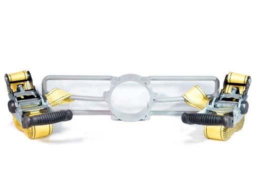
7 POLYTAPP Adapter Wrench POLYTAPP Accessory Kit Includes: POLYTAPP Tapping Adapter POLYTAPP Cutter & Pilot POLYTAPP Test Cap Optional Equipment Air Motor Torque-Reduction Gearbox POLYTAPP Clamp Page 6 of 17


8 PIPE & SADDLE PREPARATION & FUSION 1 Clean Pipe with wet cloth to remove excess dirt and contaminates. 2 Place MTD TRI FUSION branch saddle on cleaned area of pipe and mark for scraping. 3 Remove saddle and mark entire fusion Zone. 4 Peel marked area with rotary peeler to remove oxidation, contaminates. CAUTION: improper scraping on pipe will result in fusion failure 5 After scraping, utilize alcohol wipes or alcohol, and a clean, lint free cloth to clean scraped area of pipe. 6 Clean saddle fusion mat with alcohol wipes or alcohol, and a clean, lint free cloth. CAUTION: Do Not Use Less than 96% Isopropyl Alcohol. Make sure alcohol is dry prior to beginning fusion. Page 7 of 17


9 7 Remove saddle fitting from bag and attach to main by utilizing plastic undercarriage, nylon straps, or clamping device. 8 Tighten fitting until it does not move when released. Rotate fitting on main until outlet is level. 9 Once outlet is level, tighten fitting to final tension for fusion. It is imperative for a tight fit between saddle fitting and main. Tighten installation hardware until saddle fitting comes into tight contact with main, yielding no movement or gap between fitting and pipe. Assure proper tightness has been achieved by grasping the outlet of the saddle fitting and attempting to rotate it on the main with reasonable force. If fitting yields no movement, it is ready for fusion. 10 Re check outlet with level before fusion. NOTE: Pipe Ovality may create a gap between fusion mat and pipe. If this occurs, remove saddle from main and re round pipe prior to fusion. WARNING: TIGHTEN SADDLE FITTING WITH HAND TOOLS ONLY. USE OF PNEUMATIC OR AIR TOOLS IS STRICTLY PROHIBITED! OVERTIGHTENING CAN CAUSE FAILURE OF CLAMPING COMPONENTS! 11 Attach processor leads to fitting (4.7 mm pins). 12 Fuse saddle fitting to main following company procedures. Ensure that total cooling time for this fitting has completely elapsed before proceeding. Page 8 of 17


10 FITTING PREPARATION & FUSION OF POLYTAPP VALVE 1 Peel entire outlet of saddle fitting with pipe & outlet peeler. 2 Wipe outlet of saddle fitting and inside of POLYTAPP Valve coupler with alcohol wipes or alcohol, and a clean, lint free cloth. *Instructions are provided with each POLYTAPP Valve. 3 Secure valve to branch saddle for fusion utilizing an MTD POLYTAPP Clamp. 4 Attach processor leads to fitting (4.7 mm pins) and fuse POLYTAPP Valve to saddle following company procedures. 5 Ensure that cooling time printed on fitting label has elapsed before removing POLYTAPP clamp. NOTE: This is not Total Cooling Time which must be fully observed before proceeding. Page 9 of 17


11 6 Open valve and test fusion joints utilizing POLYTAPP test cap with gauge per company procedure required pressure and time. Page 10 of 17


12 TAPPING MACHINE OPERATIONS To better understand how the tapping machine operates, the operator should remove the tapping machine from its case and prepare the machine for the hot tap: 1 Retract feed tube to 0 by rotating it counter clockwise while restraining the body tube from turning. 2 Retract tap depth indicator (boring bar) to 0 inches by utilizing the ratchet handle to rotate it counter clockwise while restraining both the body and feed tubes from turning. The serrated groove at the lower end of the tap depth indicator is 0 inches. The tap depth indicator is graduated in ¼ intervals. NOTE: Body tube travel distances are predetermined ranges of travel which will place the point of the pilot at the surface of the pipe. These measurements are presented by a ½ range in order to account for thread makeup. This helps ensure that the cutter components have passed completely through the body of the valve, and are ready to begin tapping the pipe wall. In this example (4 Hot Tap on 6 SDR 11 Pipe) the body tube travel distance must be set between 16 and 16½. In this example, it is set at 16¼ which places the 4 pilot tip in contact with the surface of 6 pipe. Page 11 of 17


13 3 Thread tapping adapter onto end of tapping machine and tighten with provided spanner wrench. 4 Advance feed tube to 6, providing room to attach pilot to boring bar. Attach pilot and cutter by sliding pilot into boring bar, and tapping pilot retention clip through hole in boring bar. After attaching pilot and cutter, retract feed tube back to 0. TIP: Wrap a strip of tape around the retainer clip to prevent loss of cutter if pin breaks. 5 Insert pilot and cutter into outlet of POLYTAPP valve and attach tapping adapter to threaded portion of valve by turning entire tapping machine assembly. Ensure that the tapping adapter does not loosen at the joint indicated above. After adapter has been tightened to valve, re tighten tapping machine to adapter with spanner wrench. Before proceeding, double check tap depth indicator remains at 0 6 Ensure that valve is in open position before continuing. 7 Advance feed tube until pilot touches pipe. Ensure cutter has passed through valve by checking distance against travel chart (Pg. 16) Page 12 of 17

 to appropriate depth by attaching ratchet handle, and rotating in a clockwise")

14 9 Lock feed tube to body tube by tightening travel stop as shown to restrict movement of feed tube during tap. 10 Make note of required tap depth for the pipe SDR and size being tapped. It may be helpful to place a strip of tape on the required depth mark for reference. 11 Advance tap depth indicator (boring bar) to appropriate depth by attaching ratchet handle, and rotating in a clockwise motion 12 Once tap depth has been reached, remove travel stop and rotate feed tube clockwise ¼ turn to ½ turn to check that cutter has passed through pipe wall. If no resistance is met, pipe has been successfully tapped. If resistance is encountered, replace travel stop and advance tap depth indicator ¼ to finish tapping pipe wall. Hot Tap is Complete. Page 13 of 17


15 11 Retract tap depth indicator back to 0 by flipping ratchet direction switch on ratchet handle and rotating in a counter clockwise motion. 12 Ensure travel stop has been removed from tapping machine. 13 Retract feed tube back to 0 by rotating in a counter clockwise motion. 14 Close valve following rotation direction labeled on top of valve operator. 15 Pull up on ring to open bleeder valve. Ensure that pressure gauge reads 0 before removing adapter from valve. WARNING: VENT PRESSURE AWAY FROM EQUIPMENT AND PERSONNEL. STAND CLEAR OF VENT WHEN PRESSURE IS BEING RELEASED. Page 14 of 17


16 16 Loosen tapping adapter from valve. 17 Remove tapping machine, cutter, pilot, and adapter from valve. 18 Remove cutter from tapping machine, and remove set screw from side of cutter. 19 Tap blunt end of pilot against a block of wood to dislodge coupon from cutter. 20 Remove pilot from cutter. 21 Shavings will be retained inside cutter behind coupon. At this point, with valve in off position, remove threads from outlet of valve with polyethylene pipe cutter. After threads are removed follow manufacturer s instructions for butt fusion or electrofusion to valve outlet. After testing for leaks turn valve to the open position. Hot tap is now complete, placing new lateral line in service. Page 15 of 17
17 Tap Size (Tap Main) Travel Dimensions Body Tube Measurement Tap Depth Indicator Measurement 2 2 SDR SDR SDR 13.5 PE to PE 32/ to SDR SDR 11 PE to PE 32/ to SDR SDR SDR 11 PE to PE 32/ to SDR SDR SDR 11 PE to PE 32/ to SDR SDR SDR 11 PE to PE 32/ to SDR SDR SDR 11 PE to PE 32/ to SDR SDR SDR 11 PE to PE 32/ to SDR Page 16 of 17
18 4 8 SDR SDR 11 PE to PE 32/ to SDR SDR SDR 11 PE to PE 32/ to SDR SDR SDR 11 PE 32/ to SDR SDR SDR 11 PE 32/ to SDR SDR SDR 11 PE 32/ to SDR SDR SDR 11 PE 32/ to SDR SDR SDR 11 PE 32/ to SDR SDR SDR 11 PE 32/ to SDR Page 17 of 17
HP-104 & HP-106 Tapping Machine OPERATIONS MANUAL
 30230 Los Alamos Rd. Murrieta, CA 92563 800-279-5659 FAX 951-926-2334 TappingMachines.com HP-104 & HP-106 Tapping Machine OPERATIONS MANUAL & OPERATING INSTRUCTIONS WARNING READ: Before using this product,
LJ1-25 LouieJRtm Tapping Machine
 1/21/08 WARNING: Before using this product, read owners manual and follow all Safety Rules and Operating Instructions. LJ1-25 LouieJRtm Tapping Machine OPERATIONS MANUAL & OPERATING INSTRUCTIONS 30230
Hot Tapping Machine. OPERATIONS MANUAL and OPERATING INSTRUCTIONS
 262-2040 Hot Tapping Machine For performing 1/4 6 Hot taps 285 psi or less. Municipal Water, Sewage, & Building Services Use OPERATIONS MANUAL and OPERATING INSTRUCTIONS WARNING: These instructions are
Operation Manual Guillotine Cutter RC-5
 Operation Manual Guillotine Cutter RC-5 Technical Specifications General Safety/Operating Instructions Using the Guillotine Cutter/Crimper Blade Change Instructions Maintenance Instructions This is a detailed
Steel Spring Driven Reel Instruction Manual
 Steel Spring Driven Reel Instruction Manual WARNING: Read carefully and understand all INSTRUCTIONS before operating. Failure to follow the safety rules and other basic safety precautions may result in
APT Electrofusion Ducting
 APT Electrofusion Ducting Installation Guide Franklin Fueling Systems 3760 Marsh Rd. Madison, WI 53718 USA Tel: +1 608 838 8786 800 225 9787 Fax: +1 608 838 6433 www.franklinfueling.com Safety Important!
MUELLER GAS. No-Blo Operations Using D-5. Drilling Machine. Reliable Connections. General Information 2
 operating Instructions manual MUELLER GAS TAble of contents PAGE No-Blo Operations Using D-5 General Information 2 Installing No-Blo Service Tees, Service Stop Tees and Curb Stop Tees 3-8 Reconditioning
MUELLER. Mega-Lite Drilling Machine. Reliable Connections. table of contents PAGE. Equipment 2. Operating Instructions 3-4. Parts Information 5
 operating Instructions manual MUELLER Mega-Lite Drilling Machine table of contents PAGE Equipment 2 Operating Instructions 3-4 Parts Information 5 Travel Charts 6-11! WARNING: 1. Read and follow instructions
Operating Procedures for GripTight 15.5 SDR & IPS Test Plugs
 EST Group DC2518 08/01 REV 3 12/12 Page 1 of 6 Operating Procedures for GripTight SDR & IPS Test Plugs WARNING For proper operation, GripTight plugs must be assembled as shown in Figure 1. Pressure testing
Bray/ VAAS O-Ported Series Knife Gate Valve 770/780 Series Operation and Maintenance Manual
 Bray/ VAAS Knife Gate Valve 770/780 Series Operations and Maintenance Manual Table of Contents Definition of Terms 1 Safety Instructions 1 Introduction 2 Unpacking 2 Storage 2 Installation 2 Commissioning
Techcon Systems TS1258 Pressure Pot
 Techcon Systems TS1258 Pressure Pot User Guide TABLE OF CONTENT 1. SAFETY. 3 1.1 Intended Use 3 1.2 Safety Precaution 3 2. CERTIFICATE OF COMFORMANCE 4 3. FEATURES. 5 4. SPECIFICATIONS 5 5. INSTALLATION
Index Table. Model 794. Installation, Operating and Maintenance Instructions
 CLOCKWISE MANUAL MAKING INTO CCW TABLE Index Table Model 794 Installation, Operating and Maintenance Instructions Black & Webster Products Division 545 Hupp Ave. P.O. Box 831, Jackson, Michigan 49204 2009
Yoke Block Instruction Manual
 Yoke Block Instruction Manual ! WARNING IMPORTANT: READ MANUAL COMPLETELY BEFORE OPERATING THIS DEVICE This manual contains instructions on periodically required checks to be performed by the user. These
Product Information News
 Product Information News MMR SECOND STAGE REGULATOR VALVE CORE MSA has changed its recommended rebuilding of the MMR Second Stage Regulator s bypass sleeve assembly during the annual inspection. Based
Instruction Manual. PE Pipe Squeeze-off Tool Model TR650
 PE Pipe Squeeze-off Tool Model TR650 Instruction Manual For your personal safety READ and UNDERSTAND instructions before using tools. SAVE these instructions for future reference. SPECIFICATIONS Table
SPECIFICATIONS Type: Twin stack, single phase Tank: 4 gallon Air Output: PSI; PSI Max PSI: 125 PSI HP: 1.
 2 GALLON TWIN STACK AIR COMPRESSOR Model: 9526 DO NOT RETURN TO STORE. Please CALL 800-348-5004 for parts and service. CALIFORNIA PROPOSITION 65 WARNING: You can create dust when you cut, sand, drill or
600 / 600FC OWNER'S MANUAL
 PROGRESSION 600 / 600FC OWNER'S MANUAL Issue 2 / Version E - Dec. 10, 1997 Copyright 1997 GAMMA Sports - All Rights Reserved PROGRESSION 600 / 600FC OWNER'S MANUAL TABLE OF CONTENTS PAGE 1... WARRANTY
THE HF-300 SERIES. Operating and Service Manual. Series includes all variants of HF-300/301
 THE HF-300 SERIES Operating and Service Manual Series includes all variants of HF-300/301 Issue A July 2015 1 TABLE OF CONTENTS 1. Description... 3 2. Installation... 3 3. Operation... 4 3.1. Spring Loaded...
CP10K. 10,000 lb. Cable Puller Instruction Sheet. SAFETY ISSUES
 10,000 lb. Cable Puller Instruction Sheet CP10K SAFETY ISSUES IMPORTANT USER SAFETY AND PROTECTION: In setting up systems to fit your operations, care must be taken to select the proper components and
10 DRIP NOZZLE WATERING DRIP KIT Model / Model 46095
 10 DRIP NOZZLE WATERING DRIP KIT Model 93261 / Model ASSEMBLY AND OPERATING INSTRUCTIONS Due to continuing improvements, actual product may differ slightly from the product described herein. 3491 Mission
Continental Industries TRANSITION FITTINGS or FAX Visit
 Continental Industries TRANSITION FITTINGS 1-800-558-1373 or FAX 1-800-788-1668 Visit www.conind.com ABOUT US Our Company Continental Industries, headquartered in Tulsa, Oklahoma, was formed in 1958 and
Techcon Systems TS1254 Pressure Pot
 Techcon Systems TS1254 Pressure Pot User Guide Copyright OK International, Inc. TABLE OF CONTENT 1. SAFETY. 3 1.1 Intended Use 3 1.2 Safety Precaution 3 2. FEATURES. 5 3. SPECIFICATIONS 4 4. INSTALLATION
User Instruction Manual
 User Instruction Manual 4500 psi Air Compressor Ver 2, 1.18 Contents Parts Included...3 Assembly Instructions...3-5 Operation Instructions...6-7 Oil Change Intervals...8 Air Filter Replacement...9 Setting
Continental Industries STEEL SERVICE TEES or FAX Visit
 Continental Industries STEEL SERVICE TEES 1-800-558-1373 or FAX 1-800-788-1668 Visit www.conind.com ABOUT US Our Company Continental Industries, headquartered in Tulsa, Oklahoma, was formed in 1958 and
GAS DISTRIBUTION PRODUCTS TRANSITION FITTINGS
 GAS DISTRIBUTION PRODUCTS TRANSITION FITTINGS CONTINENTAL INDUSTRIES, INC. The Ultimate Connection CONTINENTAL INDUSTRIES, INC. ABOUT US THE ULTIMATE CONNECTION Our Company Continental Industries, Inc.,
INSTALLATION INSTRUCTIONS. CVS 67CFR Pressure Reducing Instrument Supply Regulator INTRODUCTION
 INSTALLATION INSTRUCTIONS CVS 67CFR Pressure Reducing Instrument Supply Regulator INTRODUCTION The CVS Controls 67CFR Filter regulator is a pressure reducing supply regulator typically used for pneumatic
V-24 OXYGEN LANCE VALVE
 INSTRUCTIONS for F-4737-U May, 2009 V-24 OXYGEN LANCE VALVE w/ C -Size Inlet w/ B -Size Inlet V-24 Oxygen Lance with 1/8" Pipe Holder... 9728D65... 2218939 V-24 Oxygen Lance with 1/4" Pipe Holder... 9728A65...
SHUR-LOK CORPORATION TECHNICAL SALES BULLETIN
 Page 1 of 9 1. SCOPE: 1.1. This provides the minimum design, port preparation and installation and removal requirements for SLAS4383-XX-XX, SLF2002-XX-XX and SLF3004-XX-XX adapter reducer and is applicable
INTENDED USE TECHNICAL SPECIFICATIONS
 1/2IN. HEAVY-DUTY AIR IMPACT WRENCH OWNER S MANUAL WARNING: Read carefully and understand all INSTRUCTIONS before operating. Failure to follow the safety rules and other basic safety precautions may result
3M Liqui-Cel EXF-10x28 Series Membrane Contactor
 Membrane Contactors 3M Liqui-Cel EXF-10x28 Series Membrane Contactor Assembly and Disassembly Instructions 3M.com/Liqui-Cel TABLE OF CONTENTS I. Safety and Warning 3 II. Assembly Parts 4 III. Part Orientation
INSTALLATION COMMISSIONING, OPERATION & MAINTENANCE MANUAL
 WedgeRock RW Series Worm Gear Actuators INSTALLATION COMMISSIONING, OPERATION & MAINTENANCE MANUAL Revision 01 Date 4/3/17 Page 1 Table of Contents 1.0 INTRODUCTION... 4 1.1 PURPOSE... 4 1.2 AUDIENCE...
ATS430 turbidity sensor Retractable insertion assembly
 A MEASUREMENT & ANALYTICS INSTRUCTION ATS430 turbidity sensor Retractable insertion assembly Measurement made easy 1 Introduction This publication details installation procedures for the retractable insertion
Booster Pump PB4-60 Replacement Kits
 Booster Pump PB4-60 Replacement Kits FOR YOUR SAFETY - This product must be installed and serviced by a contractor who is licensed and qualified in pool equipment by the jurisdiction in which the product
Operation Manual Piston Sensed Gas Pressure Regulators
 687 Technology Way Napa, CA 94558 Phone: (707) 259-0102 FAX: (707) 259-0117 www.aptech-online.com Operation Manual Piston Sensed Gas Pressure Regulators (Models KT9, KT10, Welded KT10, KT12) Table of Contents:
602 STRINGING MACHINE OWNER'S MANUAL
 PROGRESSION 602 STRINGING MACHINE OWNER'S MANUAL AL Issue 1- April 2000 Copyright 2000 GAMMA Sports - All Rights Reserved PROGRESSION 602 STRINGING MACHINE TABLE OF CONTENTS PAGE 1... WARRANTY PAGE 2...
DBML-60/80 Squeeze Tool
 DBML-60/80 Squeeze Tool OPERATORS MANUAL Description The Mustang Model DBML-60/80 Hydraulic squeeze tool has been manufactured since 1995. A Mustang 3 3/4 bore doubleacting cylinder producing 41,000 lbs
Yoke Block Instruction Manual
 Yoke Block Instruction Manual ! WARNING IMPORTANT: READ MANUAL COMPLETELY BEFORE OPERATING THIS DEVICE This manual contains instructions on periodically required checks to be performed by the user. These
TABLE OF CONTENTS SAFETY FIRST!...3 BASIC OPERATION...4 ADJUSTMENTS...5. Cocking Pressure...5. Three-Way Valve Adjustment...6
 TABLE OF CONTENTS SAFETY FIRST!...3 BASIC OPERATION...4 ADJUSTMENTS...5 Cocking Pressure...5 Three-Way Valve Adjustment...6 External Three-Way adjustment...6 In-Line Regulator...6 Ram to Cocking Block
Combination Breathing Apparatus
 and Combination Breathing Apparatus ULTRAVUE FACEPIECE TAL 502 (L) Rev. 0 MSA 2005 Prnt. Spec. 10000005389 (I) Mat. 10064385 Doc. 10064385 ULTRAVUE FACEPIECE COMPONENTS Item Part No. Description 800509
FRIALEN Assembly and Operating Instructions. for FRIATOP clamping unit (Top-Loading) FRIATOOLS
 FRIATOOLS") FRIALEN Assembly and Operating Instructions for FRIATOP clamping unit (Top-Loading) FRIATOOLS The FRIATOP clamping unit Tensioning belt Top loading component (e. g. tapping ball valve) Adapter Pressure
FRIALEN Assembly and Operating Instructions for FRIATOP clamping unit (Top-Loading) FRIATOOLS The FRIATOP clamping unit Tensioning belt Top loading component (e. g. tapping ball valve) Adapter Pressure
ATD /8 x 50 Retractable Air Hose Reel Owner s Manual
 ATD-31166 3/8 x 50 Retractable Air Hose Reel Owner s Manual Features Heavy-gauge, all-steel reel assembly 8-position ratchet mechanism locks reel at desired hose length 5-position adjustable roller outlet
OWNER'S MANUAL. Copyright 2003 GAMMA - All Rights Reserved
 OWNER'S MANUAL AL Issue 1 - December 2003 Copyright 2003 GAMMA - All Rights Reserved OWNER'S MANUAL TABLE OF CONTENTS PAGE 1... WARRANTY PAGE 2... ASSEMBLY INSTRUCTIONS PAGE 4... MOUNTING THE RACQUET PAGE
TECHNICAL DATA CAUTION
 Page 1 of 6 1. DESCRIPTION The Viking Model D-2 Accelerator is a quick-opening device, with an integral anti-flood assembly, used to increase the operating speed of a differential type dry pipe valve.
Freedom8 ShoeBox Compressor Manual
 Freedom8 ShoeBox Compressor Manual Warning!! This product is not a toy! Use or misuse can cause severe injury or death! Use only with adult supervision. This unit is only to be used with tanks, hoses and
PRS(TC)4,8 USER MANUAL. Read the complete manual before installing and using the regulator.
4,8 USER MANUAL. Read the complete manual before installing and using the regulator.") PRS(TC)4,8 USER MANUAL Read the complete manual before installing and using the regulator. WARNING INCORRECT OR IMPROPER USE OF THIS PRODUCT CAN CAUSE SERIOUS PERSONAL INJURY AND PROPERTY DAMAGE. Due to
PRS(TC)4,8 USER MANUAL Read the complete manual before installing and using the regulator. WARNING INCORRECT OR IMPROPER USE OF THIS PRODUCT CAN CAUSE SERIOUS PERSONAL INJURY AND PROPERTY DAMAGE. Due to
Gas Lines. Technical Manual. Sumitomo (SHI) Cryogenics of America, Inc Vultee Street Allentown, PA U.S.A.
 Cryogenics of America, Inc Vultee Street Allentown, PA U.S.A.") Gas Lines Technical Manual Sumitomo (SHI) Cryogenics of America, Inc. 1833 Vultee Street Allentown, PA 18103-4783 U.S.A. Revision F: April 2008 261320A TABLE OF CONTENTS Page DESCRIPTION...1 SPECIFICATIONS...2
Gas Lines Technical Manual Sumitomo (SHI) Cryogenics of America, Inc. 1833 Vultee Street Allentown, PA 18103-4783 U.S.A. Revision F: April 2008 261320A TABLE OF CONTENTS Page DESCRIPTION...1 SPECIFICATIONS...2
HEAVY-DUTY AIR RATCHET WRENCH OWNER S MANUAL
 HEAVY-DUTY AIR RATCHET WRENCH OWNER S MANUAL WARNING: Read carefully and understand all INSTRUCTIONS before operating. Failure to follow the safety rules and other basic safety precautions may result in
HYDRAULIC PUNCH DRIVER 38456, 38520, 7306 / 7306SB, 7310 / 7310SB, 7506, 7606SB, 7610SB, 7625 / 7625Pg / 7625PgSB, 7646 / 7646Pg / 7646PgSB
 INSTRUCTION MANUAL HYDRAULIC PUNCH DRIVER 38456, 38520, 7306 / 7306SB, 7310 / 7310SB, 7506, 7606SB, 7610SB, 7625 / 7625Pg / 7625PgSB, 7646 / 7646Pg / 7646PgSB Read and understand all of the instructions
FILTER REGULATORS MODEL NO: CAT155 & CAT156 FITTING & MAINTENANCE INSTRUCTIONS PART NO: & ORIGINAL INSTRUCTIONS
 FILTER REGULATORS MODEL NO: CAT155 & CAT156 PART NO: 3120169 & 3120170 FITTING & MAINTENANCE INSTRUCTIONS ORIGINAL INSTRUCTIONS GC0117 INTRODUCTION Thank you for purchasing this CLARKE Filter/Regulator.
MUELLER. A Wall Type. Indicator Post. Reliable Connections. General Information 2. Technical Data/ Dimensions 3. Installation 4-5.
 Installation Instructions manual MUELLER table of contents PAGE A-20814 Wall Type General Information 2 Technical Data/ Dimensions Installation 4-5 Maintenance 6 Parts 7 Indicator Post! WARNING: 1. Read
Anti-flood device Model B-1
 December 4, 2009 Dry Systems 123a 1. DESCRIPTION The Anti-flood Device is required when Viking accelerators are installed on dry systems according to Viking Model E-1 Accelerator Trim Charts. In the SET
KTM OM-2 SPLIT BODY FLOATING BALL VALVES INSTALLATION AND MAINTENANCE INSTRUCTIONS
 Before installation these instructions must be fully read and understood SECTION 1 - STORAGE 1.1 Preparation and preservation for storage All valves should be properly packed in order to protect the parts
HYDRAULIC WINCH FOR AUGERS UP TO WR10 X 71 / W130 X 41 ASSEMBLY & OPERATION MANUAL
 HYDRAULIC WINCH ASSEMBLY & OPERATION MANUAL Read this manual before using product. Failure to follow instructions and safety precautions can result in serious injury, death, or property damage. Keep manual
TriPod Safety Coupler Installation & Operating Instructions for Models TP4, TP5, TP6, and TP7
 TriPod Safety Coupler Installation & Operating Instructions for Models TP4, TP5, TP6, and TP7 March 2014 Form FVC097 - Rev03 IMPORTANT: KEEP THIS DOCUMENT WITH THE PRODUCT UNTIL IT REACHES THE END USER.
LUBRICATOR ASSEMBLY AND OPERATING INSTRUCTIONS
 AIR FILTER, REGULATOR AND LUBRICATOR 4035 ASSEMBLY AND OPERATING INSTRUCTIONS 349 Mission Oaks Blvd., Camarillo, CA 930 Visit our Web site at http://www.harborfreight.com Copyright 004 by Harbor Freight
Pressure Relief Valve Instruction Manual
 CVR3-M0_062017 Pressure Relief Valve Instruction Manual MODEL: CVR3 SFA Companies 10939 N. Pomona Ave. Kansas City, MO 64153 Tel: 888-332-6419 * Fax: 816-448-2142 E-mail: sales@bvahydraulics.com Website:
Auto-Rewind Hose Reels INSTRUCTION MANUAL FOR OXY-LPG MODEL
 Auto-Rewind Hose Reels INSTRUCTION MANUAL FOR OXY-LPG MODEL Introduction Thank you for purchasing a Retracta Auto Rewind Hose Reel. The Retracta range of hose reels are a breakthrough in industrial quality
H4802, H4802-1, H , and Pole Tampers
 SERVICE MANUAL H4802, H4802-1, H-4802-6, and 43227 Pole Tampers Serial Codes FKA, FKF, FKM, FZP, FZR, FZT, and FZV Read and understand all of the instructions and safety information in this manual before
CB7 Bayonets Male & Female 1/4", 3/8, & 1/2 Size
 12501 Telecom Drive, Tampa, FL 33637 Ph: (813) 978-1000 Fax: (813) 977-3329 www.cpc-cryolab.com INSTALLATION, OPERATING, AND MAINTENANCE INSTRUCTIONS 17/3.5.6 Rev. 0 CB7 Bayonets Male & Female 1/4", 3/8,
FIRST TEAM SPORTS, INC Storm Portable Series Assembly Instructions
 FIRST TEAM SPORTS, INC Storm Portable Series Assembly Instructions WARNING! WARNING! WARNING! THIS BASKETBALL SYSTEM IS SPRING LOADED AND SHIPPED UNDER TENSION. ATTEMPTING TO ASSEMBLE OR DISASSEMBLE ANY
PSI Mechanical Couplings
 Pipeline Accessories PSI Mechanical Couplings Systems Permasert and PermaLock Permasert and Permalock are Elster Perfection registered trade marks General Information Technical Data Installation Instructions
Hydraulic Punch Drivers
 SERVICE MANUAL 7804SB / 7806SB Quick Draw 7704SB / 7706SB Quick Draw Flex Quick Draw Hydraulic Punch Drivers Serial Codes AHJ and YZ Read and understand all of the instructions and safety information in
30T A/Manual Hydraulic Shop Press
 30T A/Manual Hydraulic Shop Press Operation Manual 1 1. Important Information 1.1 Safety Information 1.1.1 Hazard Symbols Used in the Manuals This manual includes the hazard symbols defined below when
200 STRINGING MACHINE
 200 STRINGING MACHINE OWNER S MANUAL Issue 1 - July 2010 Provided by www.gssalliance.com 200 OWNER S MANUAL TABLE OF CONTENTS WARRANTY...PAGE 2 FEATURES...PAGE 3 ASSEMBLY INSTRUCTIONS...PAGE 4 MOUNTING
Float Operated Level Controllers
 CONTENTS Float Operated Level Controllers IM0015 Nov. 2014 PAGE Introduction 1 Scope 1 Description 1 Specification 1 Control Installation 2 INTRODUCTION Side Mount Back Mount Prior to installing, the instructions
INSTALLATION INSTRUCTIONS
 KIT CONTENTS: INSTALLATION INSTRUCTIONS PART NUMBER: DESCRIPTION: E361SXA302 roof MOUNT BICycle CARRIER SINGLE Short Carriage Bolt 1x Long Carriage Bolt 3x Over-Molded Wrench 1x Button Head Screw 2x Washer
Model Air Caddy Orig TABLE OF CONTENTS
 92-0919 Orig. 020201 Model 75-0114 Air Caddy TABLE OF CONTENTS CUSTOMER MESSAGE Inside Front Cover SAFETY PRECAUTIONS 3 GENERAL DESCRIPTION 6 SPECIFICATIONS 7 MAINTENANCE 9 INSTALLATION AND OPERATION 11
RS(H)10,15 USER MANUAL. Read the complete manual before installing and using the regulator.
10,15 USER MANUAL. Read the complete manual before installing and using the regulator.") RS(H)10,15 USER MANUAL Read the complete manual before installing and using the regulator. WARNING INCORRECT OR IMPROPER USE OF THIS PRODUCT CAN CAUSE SERIOUS PERSONAL INJURY AND PROPERTY DAMAGE. Due to
RS(H)10,15 USER MANUAL Read the complete manual before installing and using the regulator. WARNING INCORRECT OR IMPROPER USE OF THIS PRODUCT CAN CAUSE SERIOUS PERSONAL INJURY AND PROPERTY DAMAGE. Due to
3/8" Dr. Air Butterfly Impact Wrench
 8192106 3/8" Dr. Air Butterfly Impact Wrench Owner s Manual Read and understand all instructions before use. Retain this manual for future reference. Specifications Construction: Polished aluminum and
X-6FC STRINGING MACHINE OWNER'S MANUAL. Issue 1 - May Copyright 2004 GAMMA Sports - All Rights Reserved
 X-6FC STRINGING MACHINE OWNER'S MANUAL Issue 1 - May 2004 Copyright 2004 GAMMA Sports - All Rights Reserved OWNER'S MANUAL GAMMA X-6FC TABLE OF CONTENTS PAGE 1... WARRANTY PAGE 2... FEATURES PAGE 3...
Retractable Hose Reel with 3/8" x 50' PVC Hose
 Retractable Hose Reel with 3/8" x 50' PVC Hose Item# 4816153 Owner s Manual Assembly and Operation Instructions MADE IN CHINA Read carefully and understand all ASSEMBLY AND OPERATION INSTRUCTIONS before
ATD LB PRESSURE BLASTER INSTRUCTION MANUAL
 ATD-8402 90LB PRESSURE BLASTER INSTRUCTION MANUAL SAVE THESE INSTRUCTIONS SAFETY INSTRUCTIONS FOR SANDBLASTER 1. Before opening the tank release the air pressure on the sand tank. To do this, turn off
35 TON HYDRAULIC PUNCH WARNING
 OPERATORS GUIDE REL-35T-PNC 35 TON HYDRAULIC PUNCH NOTICE Sizes, weights and tool specifications listed in this manual are subject to change without notice. Please consult factory for information and updates.
Mounting and Operating Instructions EB 8546 EN. Type 4708 Supply Pressure Regulators. Translation of original instructions. Type Type
 Type 4708 Supply Pressure Regulators Translation of original instructions Type 4708-53 Type 4708-64 Type 4708-12 Mounting and Operating Instructions Edition March 2018 Note on these mounting and operating
ExtendAire TM II. Intermediate Pressure Accessory Kit USER INSTRUCTIONS
 ExtendAire TM II Intermediate Pressure Accessory Kit USER INSTRUCTIONS THIS MANUAL MUST BE CAREFULLY READ AND FOLLOWED BY ALL PERSONS WHO HAVE OR WILL HAVE THE RESPONSIBILITY FOR USING OR SERVICING THIS
Purge Star & Ring Purge Systems
 March 2013 Operator s Manual Purge Star & Ring Purge Systems Additional instruction for Purge Star Single Hose, Purge Star Double (bypass) Hose and Ring Purge with bypass hose and gas dump valve feature.
ACCESSORY KIT INSTALLATION INSTRUCTIONS
 ACCESSORY KIT INSTALLATION INSTRUCTIONS 1NP0680 - PROPANE CONVERSION FOR USE WITH MODELS: PM8, PC8, PM9, PC9, FL9M, FL9C, FC9M, FC9C This conversion kit is to be installed by a qualified service agency
OWNER'S MANUAL. Copyright 1999 ATS - All Rights Reserved
 OWNER'S MANUAL AL Issue 2 - August 19, 1999 Copyright 1999 ATS - All Rights Reserved OWNER'S MANUAL TABLE OF CONTENTS PAGE 1... WARRANTY PAGE 2... ASSEMBLY INSTRUCTIONS PAGE 4... MOUNTING THE RACQUET PAGE
Model VR6 System. Installation, Operation & Maintenance
 Model VR6 System Installation, Operation & Maintenance General: All Archer Instruments chlorination systems are carefully designed and tested for years of safe, accurate field service. All Archer Instruments
20 Ton SD Shop Press Operating Instructions
 20 Ton SD Shop Press Operating Instructions MODEL NO. 850SD Hazard Symbols Used in the Manuals This manual includes the hazard symbols defined below when the operations or maintenance job involves a potential
310 SERIES TILT-TO-LOAD ROTATOR. The Specialist In Drum Handling Equipment
 OPERATOR S MANUAL FOR MORSE TILT-TO-LOAD DRUM ROTATOR SAFETY INFORMATION: While Morse Manufacturing Co. drum handling equipment is engineered for safety and efficiency, a high degree of responsibility
Tapping Tool RT3422 WARNING! OPERATOR S MANUAL
 RT3422 Tapping Tool OPERATOR S MANUAL WARNING! Read this Operator s Manual carefully before using this tool. Failure to understand and follow the contents of this manual may result in extensive property
PVC FASTTAP SADDLES for IPS Mains. Main Size OUTLET 1 FPT 3/4 CTS (7/8 OD) COMPRESSION 1 CTS (1 1/8 OD) COMPRESSION 3/4 IPS COMPRESSION
 COMPRESSION 1 CTS (1 1/8 OD) COMPRESSION 3/4 IPS COMPRESSION") PVC FASTTAP SADDLES PVC FASTTAP SADDLES for IPS Mains THE ULTIMATE CONNECTION OUTLET 3/4 IPS FEMALE SLIP OR 1 IPS MALE SLIP SOLVENT WELD 1 IPS FEMALE SLIP SOLVENT WELD 3/4 MPT 1 MPT 3/4 FPT MAIN 13/16
PVC FASTTAP SADDLES PVC FASTTAP SADDLES for IPS Mains THE ULTIMATE CONNECTION OUTLET 3/4 IPS FEMALE SLIP OR 1 IPS MALE SLIP SOLVENT WELD 1 IPS FEMALE SLIP SOLVENT WELD 3/4 MPT 1 MPT 3/4 FPT MAIN 13/16
SIGNATURE DEF REELS Models: Bare Reel Reel Reel Reel
 SERVICE BULLETIN SB2023 Rev C 7/11 SIGNATURE DEF REELS Models: 2400-006 Bare Reel 2400-007 16 Reel 2400-008 20 Reel 2400-009 30 Reel Thoroughly read and understand this manual before installing, operating
TECHNICAL DATA. Page 1 of 12
 Page 1 of 12 1. DESCRIPTION The Viking Regulating Valve is a direct-acting, single-seated, spring-loaded diaphragm valve. When installed as a pilot regulating valve on a Viking Model H or J Flow Control
SHUR-LOK CORPORATION TECHNICAL SALES BULLETIN
 Page 1 of 11 1. SCOPE: 1.1. This provides the minimum design, port preparation, and installation and removal requirements for SLAS5103 plugs and is applicable when specified on engineering drawings. These
Instruction Manual. Slug Out Knockout Driver KOMD1 / KOM540A / KOM520A
 Instruction Manual Slug Out Knockout Driver KOMD1 / KOM540A / KOM520A gardnerbender.com IMPORTANT: SHIPPING DAMAGE Visually inspect all components for shipping damage. If any shipping damage is found,
Specifications Testing & Adjusting Disassembly & Assembly
 SB4191E00 Jul. 2005 Specifications Testing & Adjusting Supplement for Quad Lift Mast D20/25/30/32/33S-3 G/GC20/25/30/32P-3 G/GC20/25/30/32E-3 Important Safety Information Most accidents involving product
Installation Instructions
 LP and High Altitude LP Gas Conversion Kit For United States Installations Installation Instructions For Model Series *G6/PGF1 Furnaces, *L1/PGC1 Furnaces, and *R4/PPG1 Gas/Electric Appliances using Honeywell
6146XX-X OPEN STYLE HOSE REELS
 OPERATOR S MANUAL INCLUDING: OPERATION, INSTALLATION & MAINTENANCE 6146XX-XXX OPEN STYLE HOSE REELS LOW, MEDIUM & HIGH PRESSURE (FOR AIR, WATER & PETROLEUM PRODUCTS) 6146XX-X RELEASED: 2-5-90 REVISED:
HD Mast Series. Installation & Operation Manual
 HD Mast Series Installation & Operation Manual South Midlands Communications Ltd SM House, School Close Chandlers Ford Industrial Estate Eastleigh, Hampshire SO53 4BY United Kingdom Tel: +44 (0)23 8024
Pontoon Slide Owner s Manual
 Pontoon Slide Owner s Manual Introduction Water sports can be safe and fun for all levels of enthusiasts. The Owner s Manual is presented to enhance your enjoyment of the sport. It is intended to alert
DK ton, Double-acting, Die-type Crimping Tool
 INSTRUCTION MANUAL DK6040 60-ton, Double-acting, Die-type Crimping Tool Read and understand all of the instructions and safety information in this manual before operating or servicing this tool. Register
NB/NBR NITROGEN BOOSTER FOR AVIATION SERVICE
 NB/NBR NITROGEN BOOSTER FOR AVIATION SERVICE INSTALLATION, OPERATION & MAINTENANCE MANUAL INTERFACE DEVICES, INC. 230 Depot Road, Milford, CT 06460 Ph: (203) 878-4648, Fx: (203) 882-0885, E-mail: info@interfacedevices.com
APG001. Application Guide for Gas. T: F: E:
 APG001 Application Guide for Gas T: 01480 442600 F: 01480 458829 E: customerservice@gpsuk.com www.gpsuk.com Application Guide for Gas Introduction 3-4 Range Overview 5-6 PE80 Yellow Pipe 7-9 Excel Yellow
COMPACT TRIPLE WALL OUTLET STATION MODEL INSTALLATION AND OPERATING INSTRUCTIONS
 COMPACT TRIPLE WALL OUTLET STATION MODEL 6255-1 INSTALLATION AND OPERATING INSTRUCTIONS To assure safe operation and conformation to local fire codes, all Porter Outlet Stations are designed to be used
Composite Pistol-Type Air Needle Scaler OWNER S MANUAL
 Composite Pistol-Type Air Needle Scaler OWNER S MANUAL WARNING: Read carefully and understand all INSTRUCTIONS before operating. Failure to follow the safety rules and other basic safety precautions may
1 DRIVE INDUSTRIAL IMPACT WRENCH
 1 DRIVE INDUSTRIAL IMPACT WRENCH 92622 ASSEMBLY AND OPERATING INSTRUCTIONS 3491 Mission Oaks Blvd., Camarillo, CA 93011 Visit our Web site at http://www.harborfreight.com Copyright 2004 by Harbor Freight
PORTABLE 5 GALLON AIR TANK ASSEMBLY & OPERATING INSTRUCTIONS
 PORTABLE 5 GALLON AIR TANK MODEL 472 ASSEMBLY & OPERATING INSTRUCTIONS 349 Mission Oaks Blvd., Camarillo, CA 930 Visit our Web site at http://www.harborfreight.com TO PREVENT SERIOUS INJURY, READ AND UNDERSTAND
MMR Air Mask With. with Quick-Connect Hose
 MMR Air Mask With with Quick-Connect Hose Upgrade Kits P/N 10025120 Slide to Connect P/N 10050038 Slide to Connect w/ Solid Cover P/N 10038666 Push To Connect P/N 10050037 Push To Connect w/ Solid Cover