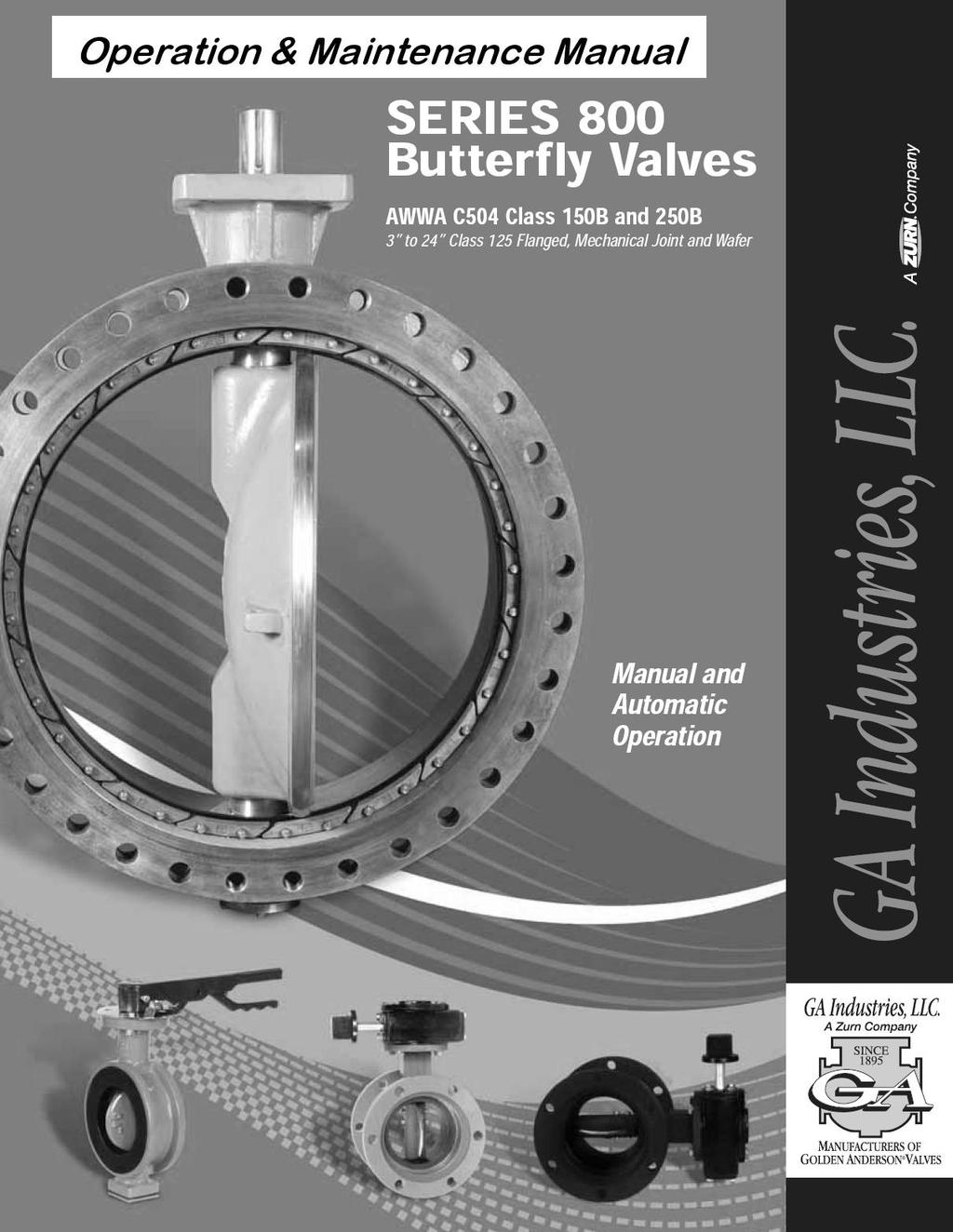
BUTTERFLY VALVES Series 800
|
|
|
- Adela Turner
- 5 years ago
- Views:
Transcription
1
2 BUTTERFLY VALVES Series 800 WARNING Before proceeding read ALL instructions and become familiar with the equipment and associated drawings. Follow ALL applicable safety regulations and codes for pressurized vessels. This manual does not purport to address the safety concerns, if any, associated with its use. It is the responsibility of the user of this manual to establish appropriate safety and health practices and determine the applicability of regulatory limitations prior to its use GENERAL The GA Series 800 Butterfly Valve is a resilient seated, quarter-turn valve, capable of providing drop tight isolation, on-off or modulating service for liquid flow control. When installed properly, these valves will provide years of maintenance free service. Failure due to faulty installation, improper operation or maintenance in such systems could result in damage, down time and costly repairs. In buried underground installations, problems or malfunctions can result in extensive, costly excavation to correct the problem. RECEIVING AND STORAGE Inspect valves on receipt for damage during shipment and conformance with quantity and description in the order. Carefully unload all valves to the ground without dropping. On smaller valves, do not lift valves with slings or chain around operating shaft, actuator, or through water-way. Instead, lift smaller valves with eyebolts or rods through flange holes. Whenever practical, store valves indoors. If not possible, protect valves and actuators from weather and accumulation of water, dirt and debris. Do not expose rubber seats to sunlight or ozone for any extended period. Valves should be stored with the valve disc or closure member slightly open. Make sure flange faces and joint sealing surfaces, body seats and disc seats are clean. Check bolts attaching actuator to valve for loosening in transit and handling. If loose, tighten firmly. Operate valve to make sure it opens and closes properly and that stops and/or limit switches are correctly set. Close valve before installing. INSTALLATION The following items must be checked during installation to ensure proper function. 1. Carefully place valves into position avoiding contact or impact with other equipment, vault walls or trench walls.
3 2. Valves are to be installed in accordance with the General Arrangement Drawings furnished for the order. 3. Foreign material in a valve can damage the rubber seat when valves are operated. Be sure valve interiors and adjacent piping are clear of foreign material prior to mating valve to pipe joint. 4. Prepare pipe ends and install valves in accordance with the pipe manufacturer s instructions for the joint used. Do no deflect pipe/valve joint. Do not use valve as jack to pull pipe into alignment. 5. In plant piping, install so as to minimize bending of valve connection with pipe loading. 6. In the case of wafer type butterfly valves, concentrically center the valve disc between the mating flanges. 7. Make sure valve disc, when opened, will not contact pipe port. This is especially necessary on pipe with linings and when wafer valves are used. Check manufacturer for minimum pipe I.D. required for clearance. CAUTION: CAUTION: It is recommended that valves be installed into piping system in accordance with AWWA M-44 in order to prevent any undue piping stress, deflection or bending that may affect the performance of the valve. On valves without actuators, discs may open or close at any time and cause injury to persons or damage to valve and other property. The shaft/disc clamping device when furnished is intended for temporary use during shipping, handling and valve installation only. Do no subject the valve to flow conditions before actuator is mounted and tested for performance, and clamping device is removed. Buried valves installed with valve boxes must be so installed that the valve box does not transmit shock or stress to the valve actuator as a result of shifting soil or traffic load. When valves are installed in vaults, the vault design must provide space for purposes of repair. The valve operating nut should be accessible from the top opening of the vault with a tee wrench. MECHANICAL JOINT INSTALLATION The successful operation of the mechanical joint requires that the plain end be centrally located in the bell and that adequate anchorage be provided where abrupt changes in direction and dead ends occur. The rubber gasket will seal more effectively if the surfaces with which it comes in contact are thoroughly cleaned (for example, with a wire brush) just prior to assembly in order to remove all loose rust or foreign material. Lubrication and additional cleaning should be performed by brushing both the gasket and the plain end with soapy water or pipe lubricant just prior to slipping the gasket into the plain end and assembling the joint.
4 For water service, the recommended range of bolt torques to be applied are given in Figure #1. When tightening bolts, it is essential that the gland be brought up toward the pipe flange evenly, maintaining approximately the same distance between the gland the face of the flange at all points around the socket. This may be achieved by partially tightening the bottom bolt first, then the top bolt; next the bolts at either side; and finally, the remaining bolts. This process should be repeated until all bolts are within the range of torques shown in Figure #1. If effective sealing is not attained at the maximum torque indicated, then the joint should be disassembled, thoroughly cleaned, and reassembled. Overstressing of bolts or mechanical joint flanges to compensate for poor installation practice is to be avoided. FIGURE #1 ~ MECHANICAL JOINT-BOLT TORQUE LOADS Valve Size Bolt Size Range of Length of Wrench * Inches Inches Torque Ft.-Lb. Inches 3 5/ / *The torque loads may be applied with torque-indicating wrenches, which may also be used to check the application of approximate torque loads applied by a person trained to give an average pull on a given length of regular socket wrench. SYSTEM TESTING When rubber seated valves are used to isolate sections of line for test, it is important to note that these valves are designed or factory set to hold rated pressure only. Test pressure in excess of factory rating may cause leakage past the rubber seat or damage to the valve. In order to prevent lost time in searching for leaks, it is recommended that excavations for buried valves not be back-filled until after hydrostatic pressure tests have been made. Seat leakage can occur due to foreign material in the line. If this occurs, open valve 5-10 degrees to get high velocity flushing action. Close and repeat several times to clear seats for tight shutoff. Seat leakage can occur due to rotational shift in position of the disc with relation to the body seat. Readjust closing stop. OPERATION Do not permit operation of any valve at pressure above the rated pressure of the valve. Do not exceed 300 ft.-lb. input torque on actuators with wrench nuts, 200 lb. rim pull input torque for handwheels and chainwheels. If portable auxiliary actuators are used, size the actuator or use a torque limiting device to prevent application of torque exceeding 300ft. lbs. If an oversize actuator with no means of limiting torque is used, stop the actuator before valve is fully opened or closed against stops and complete the operation manually. Be sure to check actuator directional switch against direction indicated on wrench nut, handwheel or records before applying opening and closing torque.
5 If a valve is stuck in some intermediate position between open and closed, check first for jamming in the actuator. If nothing is found, the interference is inside the valve. In this case, do not attempt to force the disc open or closed since excessive torque in this position can severely damage internal parts. Contact the GA service department. CAUTION: Fluids exposed to freezing temperatures may cause valve to fail resulting in injury to persons or damage to valves and other property. Do not use valves in applications that are exposed to freezing temperatures unless sufficient flow is maintained through the valve to prevent freezing, or other protection is provided. MAINTENANCE Maintenance of rubber-seated valves by owner is generally limited to actuators and shaft seals. Seat adjustment should be made in accordance with field service manuals. Unless the owner has skilled personnel and proper equipment, any major re-work will probably require removal of the valve from the line. Depending on condition, valve may require return to the manufacturer. CAUTION: Removal of actuator from valve shaft can cause disc to rotate, striking persons or objects in the disc path, causing injury to persons or damage to valve. Block or lock disc before removing actuator. Normal maintenance would be shaft packing replacement and actuator adjustment. Seal leakage, broken parts and difficult operation should be discussed with GA s Service Department before valve repairs are attempted. Stop line flow and isolate from line pressure prior to performing any corrective maintenance. After completing repair, cycle valve through one complete operating cycle and after line pressure has been restored, inspect for leakage. If major repairs require removal or closure of the valve, notify all interested personnel in the water department and fire department that the valve and line are out of service. Upon completion of repair and re-installation, notify the same personnel of the return of the valve and line to service. PARTS Order parts from your local GA Industries sales representative or directly from GA Industries. When ordering parts, please include the serial number located on the valve tag.
6 TROUBLE SHOOTING PROBLEM POSSIBLE CAUSE CORRECTIVE ACTION Leakage at shaft or Packing Loose Clean packing & valve bore between valve & and replace. actuator. Packing Worn Replace packing. Valve will not shut off Obstruction In Line Open valve to allow fluid flow or will not fully flow to flush out obstruction. close. Disc Not Fully Closed Adjust actuator closed position stop. Excessive Line Pressure Reduce pressure. Valve does not fully Position stop on actuator not Adjust actuator open position open. Set correctly. stop. Obstruction In Line Excessive Line Pressure Remove obstruction. Reduce pressure. Opening and/or closing Corroded Actuator Parts Clean & lubricate actuator torque is excessive. Parts. Valve is difficult to Loose mounting between Tighten Bolts. operate. valve & actuator. Obstruction In Line Remove Obstruction. Vibration in valve Excessive Velocity Reduce flow rate. when operating. Loose mounting between Tighten bolts. valve & actuator.
7
8
9
MUELLER. Xp, & Lineseal 350 Butterfly Valves
 Installation/Operating Manual MUELLER Lineseal Iii, Lineseal Xpii, Lineseal Xp, & Lineseal 350 Butterfly Valves! WARNING: 1. Read and follow instructions carefully. Proper training and periodic review
KENNEDY VALVE OPERATION & MAINTENANCE MANUAL
 2 54 ROTATING DISC GATE VALVE OPERATION & MAINTENANCE MANUAL Rel. 5/27/16 1 TABLE OF CONTENTS 3 General 3 Receipt & Inspection 4 Gate Valve Storage & Handling 5 6 Installation 7 Operation 8 Field Testing
INSTALLATION, OPERATION & MAINTENANCE MANUAL
 INSTALLATION, OPERATION & MAINTENANCE MANUAL AWWA C500 SOLID WEDGE GATE VALVE 2 72 NRS and OS&Y Series 100 and Series 105 TABLE OF CONTENTS SECTION PAGE # Equipment List 2 General 3 Receipt and Inspection
ROTATING DISK VALVES INSTALLATION AND MAINTENANCE 1. SCOPE 3 2. INFORMATION ON USAGE 3 3. VALVE TYPES 3 4. OPERATORS 5 5. VALVE CONSTRUCTION 6
 Sub Section INDEX Page Number 1. SCOPE 3 2. INFORMATION ON USAGE 3 3. VALVE TYPES 3 4. OPERATORS 5 5. VALVE CONSTRUCTION 6 6. INSTALLATION AND OPERATION 6 7. MAINTENANCE 8 8. REPAIR 9 9. ASSEMBLY 10 10.
Apollo Standard Port, Full Port & One Piece Flanged Ball Valves Installation, Operation, & Maintenance Manual
 I854000.D Apollo Standard Port, Full Port & One Piece Flanged Ball Valves Installation, Operation, & Maintenance Manual Introduction This manual presents guidelines for the Installation, Operation and
Bray/ VAAS O-Ported Series Knife Gate Valve 770/780 Series Operation and Maintenance Manual
 Bray/ VAAS Knife Gate Valve 770/780 Series Operations and Maintenance Manual Table of Contents Definition of Terms 1 Safety Instructions 1 Introduction 2 Unpacking 2 Storage 2 Installation 2 Commissioning
KTM V-PORT CONTROL BALL VALVES INSTALLATION AND OPERATION MANUAL
 Please read through this manual completely before operating the valves SECTION 2 - SPECIFICATIONS The safety of the valves and conformity with your equipment should be checked by the design engineer or
DelVal Flow Controls Private limited
 DelVal Flow Controls Private limited (A DIVISION OF DelTech CONTROLS LLC, USA) DelVal Series 50/5, 5A/5B Butterfly Valves INSTALLATION, OPERATION AND MAINTENANCE MANUAL ENGINEERING DATA SHEET E.D.S. NO
PRS(TC)4,8 USER MANUAL. Read the complete manual before installing and using the regulator.
4,8 USER MANUAL. Read the complete manual before installing and using the regulator.") PRS(TC)4,8 USER MANUAL Read the complete manual before installing and using the regulator. WARNING INCORRECT OR IMPROPER USE OF THIS PRODUCT CAN CAUSE SERIOUS PERSONAL INJURY AND PROPERTY DAMAGE. Due to
PRS(TC)4,8 USER MANUAL Read the complete manual before installing and using the regulator. WARNING INCORRECT OR IMPROPER USE OF THIS PRODUCT CAN CAUSE SERIOUS PERSONAL INJURY AND PROPERTY DAMAGE. Due to
INSTALLATION, OPERATION AND MAINTENANCE GUIDE
 INSTALLATION, OPERATION AND Placement in Pipeline System When installing Process Development & Control s ElastoTITE Elastomer-Hinged Check Valves in a pipeline, a minimum of five pipe diameters should
FLANGED MULTI-PORT BALL VALVES
 INTRODUCTION This instruction manual includes installation, operation and maintenance information for flanged multi-port ball valves. This manual addresses lever operated ball valves only. Please refer
FLANGED TWO-PIECE BALL VALVES
 INTRODUCTION This instruction manual includes installation, operation, and maintenance information for FNW flanged split-body ball valves. This manual addresses lever operated ball valves only. Please
INSTALLATION, OPERATION and MAINTENANCE MANUAL
 INSTALLATION, OPERATION and MAINTENANCE MANUAL TRUNNION MOUNTED BALL VALVE NEXTECH I ValvTechnologies, Inc. 5904 Bingle Road Houston, Texas 77092 U.S.A. Email: sales@valv.com www.valv.com 705_Nextech IOM
Type S301 & S302 Gas Regulators INTRODUCTION INSTALLATION. Scope of Manual. Description. Specifications. Type S301 and S302. Instruction Manual
 Fisher Controls Instruction Manual Type S301 & S302 Gas Regulators October 1981 Form 5180 WARNING Fisher regulators must be installed, operated, and maintained in accordance with federal, state, and local
FLANGED TWO-PIECE BALL VALVES
 INTRODUCTION This instruction manual includes installation, operation, and maintenance information for FNW flanged split-body ball valves. This manual addresses lever operated ball valves only. Please
APCO ARV CLEAN WATER AIR RELEASE VALVES. Model 50A
 APCO ARV CLEAN WATER AIR RELEASE VALVES Model 50A Instruction D12013 February 2017 Instructions These instructions provide installation, operation and maintenance information for APCO ARV Clean Water Air
Spilt body Flange ball valve. TC-205MFF-PN1640 User Manual English Version. Document No: TC-205MFF-PN1640.Ur-manual. Date: 2007/04/2617. Version: 1.
 Spilt body Flange ball valve TC-205MFF-PN1640 Series PED Category I,II TC-205MFF-PN1640 User Manual English Version Use for company in Europe who will place the product on the market, please amend which
DIRECT DRIVE DIXIE DOUBLE SEAMER Model 25D
 OPERATOR'S MANUAL DIRECT DRIVE DIXIE DOUBLE SEAMER Model 25D LUBRICATE DAILY: A. Gears inside gear housing at chuck shaft (1) Oil B. Seam rolls and cam rolls (4) - Oil C. Seam roll levers through gear
INSTALLATION COMMISSIONING, OPERATION & MAINTENANCE MANUAL
 WedgeRock RW Series Worm Gear Actuators INSTALLATION COMMISSIONING, OPERATION & MAINTENANCE MANUAL Revision 01 Date 4/3/17 Page 1 Table of Contents 1.0 INTRODUCTION... 4 1.1 PURPOSE... 4 1.2 AUDIENCE...
WHEATLEY WHEATLEY SERIES 500 SWING CHECK VALVE. Installation, Operation and Maintenance Manual
 WHEATLEY SERIES 500 SWING CHECK VALVE STANDARD INTEGRAL SEAT & OPTIONAL REMOVABLE SEAT 2" FP - 6" FP 150# - 1500# 8" FP - 12" FP 150# - 900# API 6D and B16.34 2" FP - 4" FP 5000# DRILLING PRODUCTION VALVE
Installation, operation & maintenance manual - original version
 Installation, operation & maintenance manual - original version AVK gate valves for water and wastewater Series 01, 02, 06, 12, 15, 18, 20, 26, 32, 33, 36, 38, 50, 55 and 636 COPYRIGHT AVK GROUP A/S 2018
RS(H)10,15 USER MANUAL. Read the complete manual before installing and using the regulator.
10,15 USER MANUAL. Read the complete manual before installing and using the regulator.") RS(H)10,15 USER MANUAL Read the complete manual before installing and using the regulator. WARNING INCORRECT OR IMPROPER USE OF THIS PRODUCT CAN CAUSE SERIOUS PERSONAL INJURY AND PROPERTY DAMAGE. Due to
RS(H)10,15 USER MANUAL Read the complete manual before installing and using the regulator. WARNING INCORRECT OR IMPROPER USE OF THIS PRODUCT CAN CAUSE SERIOUS PERSONAL INJURY AND PROPERTY DAMAGE. Due to
TITAN FLOW CONTROL, INC.
 PREFACE: This manual contains information concerning the installation, operation, and maintenance of Titan Flow Control (Titan FCI) Simplex Basket Strainers. To ensure efficient and safe operation of Titan
WHEATLEY Series 500 Swing Check Valve
 Document Number: TC003001-13 Revision: 02 WHEATLEY Series 500 Swing Check Valve Installation, Operation, and Maintenance Manual TABLE OF CONTENTS BILL OF MATERIALS...3 SCOPE...5 INSTALLATION AND OPERATION
INSTALLATION, OPERATION AND MAINTENANCE INSTRUCTIONS TYPE BV2-LD
 INSTALLATION, OPERATION AND MAINTENANCE INSTRUCTIONS TYPE BV2-LD 1. Storage & Protection 1.1. Storage The valves stay in the open position during the transportation. For incoming QC must check: a. Packing
3-PIECE BALL VALVE, 3600 PSI/ PN 248, WITH ISO DIRECT MOUNTING PAD 306M SERIES/ PED Category II
 3-PIECE BALL VALVE, 3600 PSI/ PN 248, WITH ISO DIRECT MOUNTING PAD 306M SERIES/ PED Category II 306M User Manual English Version Use for company in Europe who will place the product on the market, please
Installation & Operation Manual Proven Quality since 1892
 Content 1. ERIKS operating companies 2. Product description 3. Requirements for maintenance staff 4. Transport and storage 5. Function 6. Application 7. Installation 8. Maintenance 9. Service and repair
SECTION BUTTERFLY VALVES
 SECTION 15112 BUTTERFLY VALVES PART 1 GENERAL 1.01 SUMMARY A. All butterfly valves shall be of the tight closing, rubber seated type and fully comply with the latest revision of AWWA Standard C504, Class
TBV OPERATION AND MAINTENANCE MANUAL SERIES 2800: FLANGED BALL VALVE. For technical questions, please contact the following:
 TBV OPERATION AND MAINTENANCE MANUAL SERIES 2800: FLANGED BALL VALVE For technical questions, please contact the following: Engineering Department 1537 Grafton Road Millbury, MA 01527 Phone: (508) 887-9400
Model PIV UL/FM Post Indicator Valve. Maintenance and Operation Manual UL/FM Post Indicator Valve Configuration AWWA C515
 Model 2010 -PIV UL/FM Post Indicator Valve Maintenance and Operation Manual UL/FM Post Indicator Valve Configuration AWWA C515 2 LAYOUT AND SITING At the design stage, it should be considered where valves
INSTALLATION, MAINTENANCE & OPERATING INSTRUCTIONS 2-4 REDUCED PORT/ FULL PORT (5700/6700) ANSI CLASS 150/300/600/900/1500/2500 TRUNNION BALL VALVES
 ANSI CLASS 150/300/600/900/1500/2500 TRUNNION BALL VALVES") PBV-USA,Inc. 12735 Dairy Ashford. Stafford, Texas USA 77477 281-340-5400; 800-256-6193 FAX: 281-340-5499 INDUSTRIAL BALL VALVES IM0 69 April 2001 Rev 9 INSTALLATION, MAINTENANCE & OPERATING INSTRUCTIONS
PBV-USA,Inc. 12735 Dairy Ashford. Stafford, Texas USA 77477 281-340-5400; 800-256-6193 FAX: 281-340-5499 INDUSTRIAL BALL VALVES IM0 69 April 2001 Rev 9 INSTALLATION, MAINTENANCE & OPERATING INSTRUCTIONS
OPERATING AND MAINTENANCE MANUAL
 CONTENTS PAGE INTRODUCTION 1 Installation Compatibility 1 Required Tools and Materials 1 Preparing Valve and Flanges 1 1.0 INSTALLATION 2 1.1 INSTALLATION OF ALL 2- TO 12-IN. SPAN-TYPE VALVES 2 1.2 INSTALLATION
Assembly Drawing: W-311B-A01, or as applicable Parts List: W-311B-A01-1, or as applicable Special Tools: , , &
 REDQ Regulators Model 411B Barstock Design Powreactor Dome Regulator OPERATION AND MAINTENANCE Contents Scope..............................1 Installation..........................1 General Description....................1
KENNEDY VALVE RESILIENT WEDGE GATE VALVE MAINTENANCE MANUAL
 KENNEDY VALVE Division of McWane, Inc. 1021 East Water Street P.O. Box 931 Elmira, New York 14902-0931 Telephone (607) 734-2211 Fax (607) 734-1003 KENNEDY VALVE RESILIENT WEDGE GATE VALVE MAINTENANCE MANUAL
MUELLER A A Non-Adjustable. Vertical Indicator Posts. Reliable Connections. General Information 2. Technical Data 3.
 Installation Instructions manual MUELLER table of contents PAGE A-20808 General Information 2 Technical Data 3 Dimensions 4 A-20809 Non-Adjustable Installation 5-6 Parts 7 Maintenance 8 Vertical Indicator
641/01 AVK SWING CHECK VALVE OPERATION & MAINTENANCE MANUAL. AVK UK Limited OM270710
 AVK SWING CHECK VALVE 641/01 OPERATION & MAINTENANCE MANUAL The designs, materials and specifications shown are subject to change without notice due to our continuing programme of product development.
LRS(H)4 USER MANUAL. Read the complete manual before installing and using the regulator.
4 USER MANUAL. Read the complete manual before installing and using the regulator.") LRS(H)4 USER MANUAL Read the complete manual before installing and using the regulator. WARNING INCORRECT OR IMPROPER USE OF THIS PRODUCT CAN CAUSE SERIOUS PERSONAL INJURY AND PROPERTY DAMAGE. Due to the
LRS(H)4 USER MANUAL Read the complete manual before installing and using the regulator. WARNING INCORRECT OR IMPROPER USE OF THIS PRODUCT CAN CAUSE SERIOUS PERSONAL INJURY AND PROPERTY DAMAGE. Due to the
WKM Model 320F Floating Ball Valve
 Date: 4 WKM Model 320F Floating Ball Valve Installation, Operation, and Maintenance Manual 1 Date: 4 All the information contained in this manual is the exclusive property of Cameron. Any reproduction
English. Introduction. Safety Instructions. All Products. Inspection and Maintenance Schedules. Parts Ordering. Specifications WARNING WARNING
 Contents All Products... Gb-1 Control Valves... Gb-2 Control Valve Actuators... Gb-3 Regulators... Gb-3 Relief Valves... Gb-4 Instruments, Switches, and Accessories... Gb-4 Products Covered by Battery
MUELLER. A A Adjustable. Vertical Indicator Posts. Reliable Connections. General Information 2. Technical Data 3.
 Installation Instructions manual MUELLER table of contents PAGE A-20806 A-20807 Adjustable General Information 2 Technical Data 3 Dimensions 4 Installation 5-6 Parts 7 Maintenance 8 Vertical Indicator
INSTRUCTIONS ON INSTALLATION, OPERATION AND MAINTENANCE FOR KIRLOSKAR MULTI DOOR NON RETURN VALVES
 INSTRUCTIONS ON INSTALLATION, OPERATION AND MAINTENANCE FOR KIRLOSKAR MULTI DOOR NON RETURN VALVES KIRLOSKAR BROTHERS LIMITED MANUFACTURING UNIT, KONDHAPURI (PUNE) INDEX 1 Introduction 2 Inspections on
INSTRUCTION MANUAL. Anchor Darling 800 Globe Valves. Installation Operation Maintenance. Sizes 1/2 through 2 FCD ADENIM
 INSTRUCTION MANUAL Anchor Darling 800 Globe Valves Sizes 1/2 through 2 Installation Operation Maintenance FCD ADENIM0008-00 Revision Record Revision Section Description Date - All Original Issue 04/02/2004
MODEL 200 KNIFE GATE VALVES INSTALLATION & MAINTENANCE MANUAL
 MODEL 200 KNIFE GATE VALVES INSTALLATION & MAINTENANCE MANUAL Index 1. List of components / General arrangement 2. Description 3. Handling 4. Installation 5. Actuators / Operation 6. Maintenance a. Changing
WW-730. Pressure Sustaining/Relief Control Valve
 WW-730 Pressure Sustaining/Relief Control Valve Installation Operation & Maintenance Page 1 of 6 1. DESCRIPTION The Model 730 Pressure Relief / Sustaining Valve is an automatic control valve designed to
Declaration of Conformity as per Directive 97/23/EC
 Declaration of Conformity as per Directive 97/23/EC The manufacturer declares that:, 47906 Kempen, Germany Multi-way diverting valves Series 29a and Series 29b, with packing with lever 1. The valves are
SALCO PRODUCTS, INC. PRESSURE RELIEF VALVE STORAGE, INSTALLATION, OPERATING, MAINTENANCE/TESTING, AND INSPECTION INSTRUCTIONS
 STORAGE INSTRUCTIONS Until it is time to install a new or reconditioned valve on the car, the valve must be kept in its original packaging in order to protect it from dirt and damage. INSTALLATION INSTRUCTIONS
Installation Operation Maintenance. Bermad Level Control Valve with Modulating Horizontal Float Pilot valve One Way Flow IOM.
 Bermad Level Control Valve with Modulating Horizontal Float Pilot valve One Way Flow Model: FP 450-80 Installation Operation Maintenance PAGE 1 OF 5 1. Safety First BERMAD believes that the safety of personnel
VALVES & MEASUREMENT
 VALVES & MEASUREMENT TBV OPERATION AND MAINTENANCE MANUAL SERIES 1100: THREE PIECE BALL VALVE For technical questions, please contact the following: Engineering Department 1537 Grafton Road Millbury, MA
Model 23H Hand Crank Seamer
 OPERATOR'S MANUAL Model 23H Hand Crank Seamer If you are not experienced with your seamer, please read and understand this manual before operating the machine. If you have a question discuss it with your
Right-Angle Tube Roller Model
 SPECIFICATIONS Model no. Free Speed (RPM) Throttle Rotation Max. Torque Ft-Lb Air Pressure psi Air Inlet Hose Air Flow @Free Speed Spindle Weight 909-1700 95 Lever type Reversible 240 90 1/2 NPT 1/2 I.D.
SAPAG. Safety valves, type 5700 Storage, Use, Operation and Maintenance Instructions. IMPORTANT NOTICE
 SAPAG IMPORTANT NOTICE Contents Important notice 1 0 Valve identification 2 1 Storage 2 2 Installation 2 3 Operation 2 4 Maintenance 3 4.1 Dismantling 3 4.2 Inspection 3 4.3 Repair 3 4.4 Assembly 4 4.5
AIR COMPRESSOR OPERATING INSTRUCTION AND PARTS LIST
 AIR COMPRESSOR OPERATING INSTRUCTION AND PARTS LIST OIL-LESS TYPE IMPORTANT: PLEASE READ CAREFULLY BEFORE STARTING OPERATIONS. THE CONTENTS ARE FOR GENERAL INFORMATION OF ALL THE SIMILAR MODELS. Record
KECKLEY. Installation, Operation, and Maintenance Manual. Style KGV - Knife Gate Valve
 KECKLEY Installation, Operation, and Maintenance Manual Style KGV - Knife Gate Valve Table of Contents Introduction and Safety... 3 Safety message levels... 3 User health and safety... 3-4 Transportation
Atmospheric relief valve type 1100 Installation and maintenance instructions
 SAPAG 1. Description Sapag atmospheric relief valves type 1100 have been selected for installation because of their performance features, reliability and ease of maintenance. They are designed to protect
INSTALLATION & MAINTENANCE INSTRUCTION
 ARCHON Industries, Inc Liquid Level Gauges Models: BT-LLG ND-LLG INSTALLATION & MAINTENANCE INSTRUCTION Instruction No.: 1014.2 Revision Issued: 3/01/03 Approved: Engineering Manager Warning ONLY QUALIFIED
Installation, Operation and Maintenance Manual for Back Pressure Regulator
 Installation, Operation and Maintenance Manual for Back Pressure Regulator Model 8860 2009 Groth Corporation IOM-8860 Rev. B 12541 Ref. ID: 95565 Page 2 of 13 Table of Contents I. INTRODUCTION 3 II. DESIGN
Operating instruction
 Operating instruction MV, XV, HG, HP, RKO, D2G, TV, BV, WB & SLV 1 Introduction 2 2 Stafsjö s knife gate valves 2 3 Technical information 2 3.1 Pressure test 2 3.2 Labelling 2 4 Storage 3 5 Transportation
PP-1, PP-1W, PP-2, & PP-3
 Welker Pitot Probe Model PP-1, PP-1W, PP-2, & PP-3 The information in this manual has been carefully checked for accuracy and is intended to be used as a guide for the installation, operation, and maintenance
MUELLER. A Wall Type. Indicator Post. Reliable Connections. General Information 2. Technical Data/ Dimensions 3. Installation 4-5.
 Installation Instructions manual MUELLER table of contents PAGE A-20814 Wall Type General Information 2 Technical Data/ Dimensions Installation 4-5 Maintenance 6 Parts 7 Indicator Post! WARNING: 1. Read
Wafer Check Valve. Contents. User s Manual. (1) Be sure to read the following description of our product warranty 1
 Be sure to read the following description of our product warranty 1") Serial No. H-V066-E-3 Wafer Check Valve User s Manual Contents (1) Be sure to read the following description of our product warranty 1 (2) General operating instructions 2 (3) General instructions for
Serial No. H-V066-E-3 Wafer Check Valve User s Manual Contents (1) Be sure to read the following description of our product warranty 1 (2) General operating instructions 2 (3) General instructions for
WW-720. Pressure Reducing Control Valve
 WW-720 Pressure Reducing Control Valve (Size Ranges: 2-4 and 6-14 ) Installation Operation & Maintenance Page 1 of 6 1. DESCRIPTION The Model 720 Pressure Reducing is an automatic control valve (powered
AR STYLE FIREARMS OWNER'S MANUAL: OPERATION, HANDLING, DISASSEMBLY / REASSEMBLY & SAFETY INSTRUCTIONS
 AR STYLE FIREARMS OWNER'S MANUAL: OPERATION, HANDLING, DISASSEMBLY / REASSEMBLY & SAFETY INSTRUCTIONS - DO NOT DISCARD THIS MANUAL - READ THIS MANUAL CAREFULLY, PAYING CLOSE ATTENTION TO THE INSTRUCTIONS
Engineering Data Sheet
 Page 1 of 6 CE MARKING AND THE PRESSURE EQUIPMENT DIRECTIVE 97/23/EC Valves must be installed into a well designed system and it is recommended that the system be inspected in accordance with the appropriate
Armored Gauge O S & Y Bolted Bonnet Valves Series BB-100
 Industries, Inc. Armored Gauge O S & Y Bolted Bonnet Valves Series BB-100 INSTALLATION / OPERATION / MAINTENANCE INSTRUCTION February 22, 2002 Instr. # 1012 Approved: K. Mayer, Engineering Manager 1 TABLE
OPERATIONS/PARTS MANUAL FOR PATTERSON'S WWP75H-10 HYDRAULIC WINCH.
 W. W. Patterson Company 3 Riversea Road Pittsburgh, PA 15233 Phone: 800-322-2018 FAX: 412-322-2785 OPERATIONS/PARTS MANUAL FOR PATTERSON'S WWP75H-10 HYDRAULIC WINCH. Please fill in the following blanks
KTM OM-2 SPLIT BODY FLOATING BALL VALVES INSTALLATION AND MAINTENANCE INSTRUCTIONS
 Before installation these instructions must be fully read and understood SECTION 1 - STORAGE 1.1 Preparation and preservation for storage All valves should be properly packed in order to protect the parts
Hydrostatic Pressure Testing
 General An experienced or qualified person will be put in charge of hydro and should meet with the supervisor in charge of the job prior to test. Customer expectations should be clarified prior to beginning
Team Insert Valve Sample Specification The Insert Valve shall conform to the following:
 Team Insert Valve Sample Specification The Insert Valve shall conform to the following: The Ductile Iron 250 p.s.i.g. Insert Valve shall be a Resilient Wedge Gate Valve designed for use in potable water,
OPERATIONS/PARTS MANUAL FOR PATTERSON'S WWP40BC BARGE CONNECTOR WINCH
 W. W. Patterson Company 3 Riversea Road Pittsburgh, PA 15233 Phone: 800-322-2018 FAX: 412-322-2785 OPERATIONS/PARTS MANUAL FOR PATTERSON'S WWP40BC BARGE CONNECTOR WINCH Please fill in the following blanks
OPERATOR'S MANUAL DIRECT DRIVE DIXIE DOUBLE SEAMER Model 10D
 OPERATOR'S MANUAL DIRECT DRIVE DIXIE DOUBLE SEAMER Model 10D OIL DAILY: A. Gears inside gear housing through oil groove in gear housing at cut surface of chuck shaft. (Oil through #517 gear housing cover
AcornVac Vacuum Plumbing Systems - Trouble Shooting Guide
 AcornVac Vacuum Plumbing Systems - Trouble Shooting Guide 1. Accumulators Problem Accumulator is overflowing If Accumulator continues to overflow Correction 1. Push and hold the manual activation button
OPERATIONS/PARTS MANUAL FOR PATTERSON'S MODEL # WWP40M-LPS-6 LOW-PROFILE BARGE CONNECTOR WINCH
 W. W. Patterson Company 3 Riversea Road Pittsburgh, PA 15233 Phone: 800-322-2018 FAX: 412-322-2785 OPERATIONS/PARTS MANUAL FOR PATTERSON'S MODEL # WWP40M-LPS-6 LOW-PROFILE BARGE CONNECTOR WINCH Please
INSTALLATION, OPERATION AND SERVICE MANUAL ABS AIR BAG LIFT
 INSTALLATION, OPERATION AND SERVICE MANUAL ABS AIR BAG LIFT P.O. Box 1058 1058 West Industrial Avenue Guthrie, OK 73044-1058 405-282-5200 FAX: 405-282-8105 www.autoquip.com Item # 830ABS Version 1.0 07/2001
Pressure Dump Valve Service Kit for Series 2300 Units
 Instruction Sheet Pressure Dump Valve Service Kit for Series 00 Units. Overview The Nordson pressure dump valve is used to relieve hydraulic pressure instantly in Series 00 applicator tanks when the unit
EASTERN ENERGY SERVICES PTE LTD. 60 Kaki Bukit Place #02-19 Eunos Tech Park Singapore, SG Singapore Telephone: Fax:
 2 Table Of Contents 1. Introduction 3 2. About this Manual 3 3. Contacting YZ Systems 3 4. Vessel Components 4 5. Specifications 5 6. Application 6 7. Theory of Operation 7 8. DuraSite Installation & Use
Summary of Accumulators These operating instructions apply to the accumulators listed in the table shown below.
 Page 1 of 15 Summary of Accumulators These operating instructions apply to the accumulators listed in the table shown below. Model Number A25-XXXX-3.6K Series A40-XXXX-3K Series A40X-XXXX-3.6K Series A60-XXXX-3K
Telefon (+45) Telefax (+45)
 Telefax (+45)") Uni-Valve A /S VENTILER & INSTRUMENTER Telefon (+45) 43 43 82 00 Telefax (+45) 43 43 74 75 mail@uni-valve.com www.uni-valve.com UNI-S83 / S84 3/4-way ball valve Installation and Operating manual 3/4-WAY
Uni-Valve A /S VENTILER & INSTRUMENTER Telefon (+45) 43 43 82 00 Telefax (+45) 43 43 74 75 mail@uni-valve.com www.uni-valve.com UNI-S83 / S84 3/4-way ball valve Installation and Operating manual 3/4-WAY
Installation, Operation, and Maintenance Manual
 Installation, Operation, and Maintenance Manual Welker Probe Instrument Regulator Model The information in this manual has been carefully checked for accuracy and is intended to be used as a guide for
DC5A. Cyclone Separator Trap for Air. Copyright 2015 by TLV Co., Ltd. All rights reserved ISO 9001/ ISO MA-03 (DC5A) 19 June 2015
 19 June 2015") 172-65205MA-03 (DC5A) 19 June 2015 ISO 9001/ ISO 14001 Manufacturer Kakogawa, Japan is approved by LRQA LTD. to ISO 9001/14001 Cyclone Separator Trap for Air DC5A Copyright 2015 by TLV Co., Ltd. All rights
172-65205MA-03 (DC5A) 19 June 2015 ISO 9001/ ISO 14001 Manufacturer Kakogawa, Japan is approved by LRQA LTD. to ISO 9001/14001 Cyclone Separator Trap for Air DC5A Copyright 2015 by TLV Co., Ltd. All rights
COMBINATION AIR RELEASE DEGASSING (CARD) VALVES INSTALLATION AND MAINTENANCE MANUAL
 VALVES INSTALLATION AND MAINTENANCE MANUAL") COMBINATION AIR RELEASE DEGASSING (CARD) VALVES INSTALLATION AND MAINTENANCE MANUAL SPECIFICATIONS: The CARD series air valves are available in 3 pipe sizes, 1, 2 and 4 NPT or socket. Maximum inlet pressure
COMBINATION AIR RELEASE DEGASSING (CARD) VALVES INSTALLATION AND MAINTENANCE MANUAL SPECIFICATIONS: The CARD series air valves are available in 3 pipe sizes, 1, 2 and 4 NPT or socket. Maximum inlet pressure
WW-720. Pressure Reducing Control Valve
 WW-720 Pressure Reducing Control Valve (Size Ranges: 2-4 and 6-14 ) Installation Operation & Maintenance Page 1 of 6 1. DESCRIPTION The Model 720 Pressure Reducing is an automatic control valve (powered
INSTALLATION / OPERATION / MAINTENANCE INSTRUCTION
 ARCHON Industries, Inc. Armored Gauge Valves Model series 700 & 900 INSTALLATION / OPERATION / MAINTENANCE INSTRUCTION Instruction # 1011 Rev. B Issued: July 22, 2003 Approved: K. Mayer, Engineering Manager
IN-PLANT VALVES. Serving the Water & Waste Water Industry Since Clow Valve is a division of McWane, Inc.
 Serving the Water & Waste Water Industry Since 1878 IN-PLANT VALVES Clow Valve is a division of McWane, Inc. www.clowvalve.com AUTOMATION MORIN ACTUATOR DESCRIPTION: The Morin Actuator is a heavy-duty,
Installation Instructions For Flat Seated Bolted Type RAH Series Disk Holders
 Installation Instructions For Flat Seated Bolted Type RAH Series Disk Holders RA Series Rupture Disks 1. WARNING a) Read the complete instructions before attempting to install the rupture disk and holder
Nextech. Trunnion - Mounted Ball Valve. Installation and Operations Maintenance Manual
 Nextech Trunnion - Mounted Ball Valve Installation and Operations Maintenance Manual After ValvTechnologies NEXTECH valves are assembled and tested, the valves are left in the full open position and end
APCO ASU-SCAV & ASU-CAV SINGLE BODY COMBINATION AIR VALVES
 APCO ASU-SCAV & ASU-CAV SINGLE BODY COMBINATION AIR VALVES Instruction D12039 December 2015 Instructions These instructions provide installation, operation and maintenance information for the. They are
CB7 Bayonets Male & Female 1/4", 3/8, & 1/2 Size
 12501 Telecom Drive, Tampa, FL 33637 Ph: (813) 978-1000 Fax: (813) 977-3329 www.cpc-cryolab.com INSTALLATION, OPERATING, AND MAINTENANCE INSTRUCTIONS 17/3.5.6 Rev. 0 CB7 Bayonets Male & Female 1/4", 3/8,
Operation Manual Air Saver Unit ASV5000 Series
 9IM-V066-b Operation Manual Air Saver Unit ASV5000 Series Thank you for your choice of Kuroda Pneumatics LTDs product on this time. Please read this operation manual carefully and use the product correctly.
Model GP PRESSURE REDUCING VALVE Installation & Operation Manual
 Model GP-2000 PRESSURE REDUCING VALVE Installation & Operation Manual Please read this bulletin thoroughly before using the pressure reducing valve, so that you may do so correctly and safely. Please carefully
Installation Troubleshooting Maintenance Instructions Installation / Start-up
 Model ZW207 Installation Troubleshooting Maintenance Instructions Installation / Start-up NOTE: Flushing of all pipe lines is to be performed to remove all debris prior to installing valve. 1. For making
VALVE GLOBE CAM TS OF 11 DOC NO REV. NO DATE PAGE NO. maximum life. DESIGN CONDITION 1g of force in. property damage.
 CAM TS 31 1 OF 11 1.0 GENERAL It is recommended that this entire document shall be read prior to proceeding with the installation or repair. Only correct installation, maintenance and operation will ensure
VRS Assembly & Operating Instructions
 VRS Assembly & Operating Instructions Models VRS-18 Pn #270003 VRS-24 Pn #270006 VRS-30 Pn #270010 Not for use on pressure vessels equipped with Automatic exhaust valve (680 controls) EMPIRE ABRASIVE EQUIPMENT
Instructions for Installation, Operating and Maintenance
 Instructions for Installation, Operating and Maintenance for ABO butterfly valves series 500 1) Introduction 2) Safety Instructions 3) Valve Identification 4) Transportation and Storage 5) Installation
Float Operated Level Controllers
 CONTENTS Float Operated Level Controllers IM0015 Nov. 2014 PAGE Introduction 1 Scope 1 Description 1 Specification 1 Control Installation 2 INTRODUCTION Side Mount Back Mount Prior to installing, the instructions
ARGUS MODEL C PIG VALVE
 ARGUS MODEL C Installation, Operation, and Maintenance Manual Dedicated to Improving Your Operations for Over 50 Years Argus Machine Co. Ltd. 5820-97 Street, Edmonton, Alberta, Canada T6E 3J1 Phone: (780)
Contents. 1. General information BROEN BALLOMAX Steel Ball Valves Approvals Quality Management...2
 Contents 1. General information...2 1.1 BROEN BALLOMAX Steel Ball Valves...2 1.2 Approvals...2 1.3 Quality Management...2 2. Preoperational Instructions and Precautions...2 3. Plates...3 4. Transport and
Model GPR Primary Pressure Regulating Valve. Instruction Manual
 Model GPR-2000 Primary Pressure Regulating Valve Instruction Manual Please read this instruction manual thoroughly before using the primary pressure regulating valve, so that you may do so correctly and
AWWA C504 COMPLIANT VALVES FROM 3 THRU 108
 AWWA C504 COMPLIANT VALVES FROM 3 THRU 108 PO Box 411 Berwick PA 18603 800-247-VALV www.crispinvalve.com 500 SERIES: Sizes 3-20 Available The K-Flo 500 Series is a heavy-duty resilient seated butterfly
Bermad Model:
 Bermad Model: 405-02 Manually Operated Hydraulic Valve INSTALLATION OPERATION MAINTENANCE Application Engineering BERMAD 1. Safety First BERMAD believes that the safety of personnel working with and around
PISTOL CALIBER AR STYLE FIREARMS
 PISTOL CALIBER AR STYLE FIREARMS OWNER'S MANUAL: OPERATION, HANDLING, DISASSEMBLY / REASSEMBLY & SAFETY INSTRUCTIONS - DO NOT DISCARD THIS MANUAL - READ THIS MANUAL CAREFULLY, PAYING CLOSE ATTENTION TO