USER MANUAL. m 2 multi AAD. It could save you... More than you think EN
|
|
|
- Scarlett Mitchell
- 5 years ago
- Views:
Transcription

1 USER MANUAL m 2 multi AAD It could save you... More than you think EN
2 CONTENTS CONTENTS WARNING 1. Introduction 1.1. General description 1.2. Operating principle 2. m 2 multi description 2.1. Construction 2.2. Processing unit 2.3. Control Unit 2.4. Cutter 3. Profiles 3.1. Description 3.2. List of profiles STUDENT (Stu) INTERMEDIATE (Int) PROFESSIONAL (Pro) CANOPY PILOTING (CPi) TANDEM (TAn) 3.3. Profile charts 3.4. Profile parameters 3.5. AdJUSt description and use 4. Operating mode 4.1. Description 4.2. List of modes BASIC mode OFFSEt HI mode OFFSEt LO mode 4.3. Examples of using modes BASIC mode - example OFFSEt HI mode - setting and example a. OFFSEt HI mode - sequence OFFSEt LO mode - setting and example a. OFFSEt LO mode - sequence 5. Controls 5.1. Control basics 5.2. Switching the device on and off Switch on sequence Switch off sequence 5.3. Changing the profile Profile changes sequence 5.4. INFO Access INFO with device ON Access INFO with device OFF Meaning of individual letters Gravity index 5.5. Error messages List of errors and their numbers 6. SEtUP 6.1. SCALE setting description SCALE setting sequence 6.2. ProFilE setting descrption ProFilE setting sequence 6.3. AdJUSt setting description AdJUSt settings sequence 7. Important limits and limit modes 7.1. Use in pressurized aircraft 7.2. Altitude lock 7.3. Water jumps 7.4. Instructions for the pilot 7.5. Important operation principles 8. Installation 8.1. Installation procedure 8.2. Securing closing loop 9. Maintenance 9.1. Cutter replacement 9.2. Filter replacement 9.3. Battery 9.4. Annual inspection Inspection procedure 10. Technical data Basic technical data Device service life Cutter service life Warranty 11. Disclaimer 12. Appendices X-RAY Card 2
3 WARNING Skydiving is a dangerous activity that can result in serious or even fatal injury. To reduce these risks, it is necessary to have training and experience. Using the m 2 multi automatic activation device when skydiving can significantly reduce these risks. Never rely solely on the m 2 multi, since it is not the primary tool for opening of your parachute. Keep in mind that the m 2 multi is an electronic device and, just like any other equipment, it can fail. In some collisions the m 2 multi may even cause death. Read the instructions thoroughly before using the device. The device is not designed for PARAGLIDING, PARASCENDING, PARASAILING and BASE JUMPING. Even a flawless operation of the m 2 multi cannot ensure proper operation of the parachute kit, i.e. the harness with container, reserve parachute and other equipment. The m 2 multi device is only responsible for cutting the reserve parachute closing loop that is properly pulled through the cutter!!! The specified activation altitude (AGL) of the m 2 multi is based on a skydiver in a stable body position. If the skydiver is in another orientation, or unstable, this may result in pressure changes that cause the m 2 multi to activate above the specified altitude (AGL). To avoid premature activation of the m 2 multi the skydiver should be in a stable body position and comply with the recommended altitudes (AGL) for main canopy deployment. In addition, the skydiver should be aware that it is possible to exceed the specified limits under canopy and cause the m 2 multi to activate. The Gravity Index is designed to show you how close you are to activation of the device under canopy, and we recommend that users become familiar with this feature (see chapter ). 3

4 1. Introduction 1.1. General description Thank you for purchasing the m 2 multi AAD and we hope that you never find yourself in a situation in which you would need to use it. Simply switch on the m 2 multi in the chosen profile before the first jump and it will quietly guard your safety from that moment until it is switched off again. The AAD Automatic Activation Device is an automatic electronic safety device. The m 2 multi device continuously checks that the skydiver is not too close to the ground without an open and functional parachute. It ensures the fall rate and altitude of the skydiver. If the m 2 multi evaluates the situation as dangerous for the skydiver, its cutter automatically cuts the reserve parachute closing loop and thus initiates the sequence of reserve parachute deployment. It is designed and manufactured on the basis of the latest findings focused on sport skydiving and its functions fully comply with the requirements of current skydiving sport. Professional engineers who are themselves excellent skydivers participated in its development. The device has five different profile settings: STUDENT, INTERMEDIATE, PROFESSIONAL, CANOPY PILOTING and TANDEM. When switched on, the m 2 multi works fully automatically, without any user intervention Main advantages The main advantages of the m 2 multi device are: - ultra low power design - no battery replacement necessary for the service life duration - service life 15 years + 6 months without the need to perform the prescribed servicing by the manufacturer - compact smooth rounded metal construction - minimum thickness of the body and the control unit - water resistance up to 2m in salt or fresh water - simple operation and many sophisticated additional features - special flat cutter design with a knife to cut the closing loop 1.3. Operating principle The m 2 multi is an electronic automatic activation device, operating on the principle of pressure reading. The primary means for detecting the altitude and fall rate is a pressure sensor. The altitude is calculated based on the difference between two atmospheric pressures. The pressure at current altitude and pressure on landing location GROUND ZERO. The pressure on the landing location is measured and set after switching on the device during calibration. This pressure is automatically adjusted by a change in barometric pressure during the day without the need for user intervention. The m 2 multi checks the ambient barometric pressure every 32 seconds and it determines whether the aircraft has taken off. If yes, it begins to monitor the skydiver s altitude and fall rate. The pressure sensor measures the atmospheric pressure 8x per second in free fall. The information collected is evaluated by means of a microprocessor and ingenious software and it is converted to real fall rate and altitude. Thanks to this, the m 2 multi device is capable of meeting the preset criteria of fall rate in combination with altitude above the landing location, cut the reserve parachute closing loop by means of the cutter and thus initiate the deployment sequence. The device is activated only in the case the preset criteria are met; the criteria differ depending on the set profiles - STUDENT (Stu), INTERMEDIATE (Int), PROFESSIONAL (Pro), CANOPY PILOTING (Cpi) and TANDEM (Tan). 4


5 2. m 2 multi description 2.1. Construction The m 2 multi is designed to best meet the requirements for durability and correct operation in all situations. It strives not to restrict the skydiver. It works with minimum power consumption, which allows it to maintain sufficient capacity of the energy source for its entire service life without having to replace the battery. It is built inside a minimum-size cover and thus gives the skydiver the possibility to open the reserve parachute without using the manual handle. The m 2 multi consists of a processing unit with the battery, processor, electronic circuits and a pressure sensor. The processing unit is connected to the control unit by means of a cable; the control unit contains a multifunction display and control button. The cutter connected in the processing unit body via a connector as a removable part of the device Processing unit The body of the processing unit is made of aluminum alloy and its surface is coated. The front face of the unit bears the m 2 multi logo and on the back there is the identification label. Between the cables on the top side there is a filter. The whole body is watertight. The identification label indicates the following information: - SN (Serial Number), unique serial number - MFD (Manufacture Date), year and month of manufacture - m 2 multi AAD, commercial designation - Made in Czech Republic and EU, country of origin - logo and other specifications required for such a device 5


6 2. m 2 multi description 2.3. Control unit The body of the control unit is made of stainless steel and is connected to the processing unit by a flexible cable. The unit has a display for the various icons and a control button. Only press the control button with the pad of your finger! Display Control button 2.4. Cutter The cutter is made of stainless steel and cuts the reserve parachute closing loop, if necessary. Its shape allows it to be firmly fixed between the reserve parachute container flaps and it prevents the cutter body from turning around its longitudinal axis. It is highly scratch resistant. It is connected to the main unit via a flexible cable and a connector. The connector is completely inserted into the processing unit and is secured with a locking screw to prevent accidental removal. 9 mm diam. 8 mm diam. 10 mm diam. 3,8 mm 8 mm 55 mm 6
7 3. Profiles 3.1. Description Profile is a set of parameters that determine the conditions for activation of the m 2 multi device. The most important parameters are the activation altitude and the fall rate. The parameters of the individual profiles are fixed. The user may select and set a profile depending on his skills, used parachute and sports performance or focus. The profile setting is permanent and may be changed in the SETUP menu List of profiles STUDENT (Stu) INTERMEDIATE (Int) PROFESSIONAL (Pro) CANOPY PILOTING (CPi) TANDEM (TAn) STUDENT (Stu) The STUDENT profile is designed for basic training of students and AFF. It is activated when the height above the landing location is lower than approx. 330m / 1 100ft and fall rate is higher than approx. 13m.s -1 / 29mph. The altitude lock opens at approx. 450m / 1 475ft. The device does not activate when below approx. 60m / 195ft. The activation zone is thus in the range of approx. 330m to 60m / 1 100ft to 195ft above the landing location. Warning: The speed of approx. 13m.s -1 / 29mph may be also reached with a fully functional parachute! If the student-skydiver does not go on with the jump and lands on board the aircraft, switch off the m 2 multi device always in the STUDENT setting. If this is not possible, the aircraft must not descend faster than approx. 13m.s -1 / 29mph. 7

8 3. Profiles INTERMEDIATE (Int) The INTERMEDIATE profile is designed for basic training of advanced students and AFF. It is activated when the height above the landing location is lower than approx. 330m / 1 100ft and fall rate is higher than approx. 20m.s -1 / 45mph. The altitude lock opens at approx. 450m / 1 475ft. The device does not activate when below approx. 60m / 195ft. The activation zone is thus in the range of approx. 330m to 60m / 1 100ft to 195ft above the landing location. It is the recommended setting for students after completing the first ten jumps. It is solely upon the decision of the instructor to determine the setting and suitability of its use for a particular student. Warning: The speed of approx. 20m.s -1 / 45mph may be also reached with a fully functional parachute! If the student-skydiver does not go on with the jump and lands on board the aircraft, switch off the m 2 multi device always in the INTERME- DIATE setting. If this is not possible, the aircraft must not descend faster than approx. 20m.s -1 / 45mph PROFESSIONAL (Pro) The PROFESSIONAL profile is the most commonly used setting of the device. Is designed for experienced skydivers. It is activated when the height above the landing location is lower than approx. 270m / 885ft and fall rate is higher than approx. 35m.s -1 / 78mph. The altitude lock opens at approx. 450m / 1 475ft. The device does not activate when below approx. 100m / 330ft. The activation zone is thus in the range of approx. 270m to 100m / 885ft to 330ft above the landing location. Warning: The speed of approx. 35m.s -1 / 78mph may be also reached with a fully functional parachute! If you are using a high-performance parachute, check the GRAVITY index! (Section ). 8
9 3. Profiles CANOPY PILOTING (CPi) The CANOPY PILOTING profile is primarily intended for the Canopy Piloting sports discipline. The profile is used only for the most experienced pilots with extremely quick parachutes and vast experience. It is activated when the height above the landing location is lower than approx. 270m / 885ft and fall rate is higher than approx. 45m.s -1 / 101mph. The altitude lock opens at approx. 450m / 1 475ft. The device does not activate when below approx. 150m / 490ft. The activation zone is thus in the range of approx. 270m to 150m / 885ft to 490ft above the landing location. Warning: The speed of approx. 45m.s -1 / 101mph may be also reached with a fully functional parachute! TANDEM (TAn) The TANDEM profile is designed for tandem kits. It is activated when the height above the landing location is lower than approx. 610m / 2 000ft and fall rate is higher than approx. 35m.s -1 / 78mph. The altitude lock opens at approx. 900m / 2 950ft. The device does not activate when below approx. 100m / 330ft. The activation zone is thus in the range of approx. 610m to 100m / 2 000ft to 330ft above the landing location. 9
10 3. Profiles 3.3. Profile charts 900 TANDEM approx. 900m approx. 2,950ft alt - lock 2, , , approx. 610m approx. >35m/s approx. 2,000ft approx. >78mph 1, STUDENT INTERMEDIATE PROFESSIONAL CANOPY PILOTING 1, approx. 450m approx. 1,475ft alt - lock approx. 450m alt - lock approx. 1,475ft approx. 450m approx. 1,475ft alt - lock approx. 450m approx. 1,475ft alt - lock 1, approx. 330m approx. >13m/s approx. 1,100ft approx. >29mph approx. 330m approx. >20m/s approx. 1,100ft approx. >45mph approx. 270m approx. >35m/s approx. 885ft approx. >78mph approx. 270m approx. >45m/s approx. 885ft approx. >100mph approx. 100m approx. 330ft approx. 150m approx. 490ft approx. 100m approx. 330ft 330 approx. 60m approx. 195ft approx. 60m approx. 195ft 0 altitude (m) 0 altitude (ft) Parameters in chapter
11 3. Profiles 3.4. Profile parameters m 2 multi STUDENT (Stu) m 2 multi CANOPY PILOTING (CPi) Altitude lock (Alt-Lock) Activation zone begins (Top) Activation zone ends (Bottom) Activation speed approx. 450m / 1 475ft approx. 330m / 1 100ft approx. 60m / 195ft approx. > 13m.s -1 / 29mph Altitude lock (Alt-Lock) Activation zone begins (Top) Activation zone ends (Bottom) Activation speed approx. 450m / 1 475ft approx. 270m / 885ft approx. 150m / 490ft approx. > 45m.s -1 / 101mph m 2 multi INTERMEDIATE (Int) m 2 multi TANDEM (TAn) Altitude lock (Alt-Lock) Activation zone begins (Top) Activation zone ends (Bottom) Activation speed approx. 450m / 1 475ft approx. 330m / 1 100ft approx. 60m / 195ft approx. > 20m.s -1 / 45mph Altitude lock (Alt-Lock) Activation zone begins (Top) Activation zone ends (Bottom) Activation speed approx. 900m / 2 950ft approx. 610m / 2 000ft approx. 100m / 330ft approx. > 35m.s -1 / 78mph m 2 multi PROFESSIONAL (Pro) Altitude lock (Alt-Lock) Activation zone begins (Top) Activation zone ends (Bottom) Activation speed approx. 450m / 1 475ft approx. 270m / 885ft approx. 100m / 330ft approx. > 35m.s -1 / 78mph 11

12 3. Profiles 3.5. AdJUSt description and use The individual profiles and their activation parameters are fixed in the process of manufacture. Some users may prefer a higher activation altitude, which gives them more time to deal with an emergency in case of activation. In some countries or at some dropzones a higher activation altitude may be required by local regulations. The AdJUSt function allows the user to modify the current profile and increase the activation altitude in case this is considered necessary. In the current profile the Top activation altitude may be increased in several steps, A1 to A9. The individual increments are approx. 30 m / 100 ft. The maximum increase in the activation altitude is approx m / 900 ft. The AdJUSt setting is permanent and is displayed together with the current profile on the control unit display. Warning: - The altitude lock increases adequately according to the selected step A1 to A9! (Section 7.2.) - Take care to open the main parachute in time as you may quickly reach the activation altitude! Procedure of setting the AdJUSt function can be found in Section
13 4. Operating mode 4.1. Description The m 2 multi device may be switched on in several modes. The mode is selected when the device is switched on and remains active until it is switched off again - the selection is not permanent. The various modes are used to distinguish the type of jump and they determine the device behavior. BASIC mode is used most often - when the skydiver performs the jump at an airport (dropzone) and the aircraft take-off point and the landing location are thus the same - they are at the same elevation. OFFSEt mode must be always used when the take-off and landing locations are at different elevations. OFFSEt mode allows the user to enter the elevation difference between the aircraft take-off point and the landing location during the switch on sequence. If the device is switched on in BASIC mode, the current profile is shown on the display. If the device is switched on in OFFSEt mode, the display shows, the first letter of the profile, the entered elevation difference between the aircraft take-off point and the landing location, and the units icon. When the button is depressed, the full description of the current profile is displayed List of modes - BASIC It is used when the skydiver takes-off and lands at the same place. - OFFSEt HI It is designed for situations when the landing location is higher (elevation) than the elevation at which the device was switched on. - OFFSEt LO It is designed for situations when the landing location is lower (elevation) than the elevation at which the device was switched on BASIC - mode The BASIC mode shall be used always, when the skydiver starts (take-off point of the aircraft), and lands at the same place, usually the drop zone and does not need to change the device parameters due to higher or lower landing location. The landing location is in this case at the same elevation as the take-off point of the aircraft, where the device was switched on. Always switch on Ground zero approx. +130ft / + 40m Unlocking altitude of Altitude lock approx. +450m / +1475ft - Stu, Int, Pro, CPi approx. +900m/ +2950ft - TAn Restricted area the device at the landing location. The m 2 multi requires the plane to immediately climb approx. 40m/130ft above Ground Zero for a correct detection of start-up and remain above this altitude until the skydivers jump off. In the next phase of the flight it is necessary to exceed the Altitude lock (watch out for increasing the unlocking altitude, see Section 6.3.) according to the preset device profile (approx. 450m/ 1 475ft - Stu, Int, Pro, Cpi, (ca 900m / 2 950ft - Tan) to unlock the device. 13
14 4. Operating mode OFFSEt HI - mode OFFSET HI mode is designed for situations when the landing location is higher (elevation) than the elevation at which the device was switched on (take-off point of the aircraft). It is necessary to set the elevation difference of the landing location in the range of approx. +/- 999m / +/ ft. Reminder: This is a temporary setting for one jump only! The settings can only be done when switching on the device. When using the OFFSET HI mode, the altitude at which the altitude lock opens relates to the preset landing location elevation. It is also necessary to bear this fact in mind in case of an emergency situation! Switch on the device at the take-off point of the aircraft. For correct operation of the m 2 multi it is necessary to preset the elevation difference between the landing location and the takeoff location. Enter the numeric value of the difference between the parachutist landing location and the aircraft take-off point. The altitude lock is in this case relates to the landing location, i.e. according to the profile either approx. +450m / ft for profiles Stu, Int, Pro and Cpi or about +900m / ft for profile Tan plus the specified elevation difference. In such case, the m 2 multi requires the plane to immediately climb approx. 40m/130ft above the take-off point for a correct detection of start-up and remain above this altitude. After reaching the preset altitude plus approx. 40m / 130ft and exceeding it, the aircraft shall remain above this level until the skydivers jump off. If the skydiver lands at the preset altitude, the device switches off automatically. If the device does not switch off automatically, do it manually after landing. Switch the device on only before the following jump. This ensures perfect calibration and operation of the m 2 multi device. Ground zero approx ft / + 40m Unlocking altitude of Altitude lock approx. +450m / +1475ft - Stu, Int, Pro, CPi approx. +900m/ +2950ft - TAn Restricted area approx ft / + 40m Restricted area 14
15 4. Operating mode OFFSEt LO - mode OFFSET LO mode is designed for situations when the landing location is lower (elevation) than the elevation at which the device was switched on. In this mode, you can set the elevation difference of the landing location in the range of approx. +/- 999m / +/ ft. Reminder: This is a temporary setting for one jump only! The settings can only be done when switching on the device. When using the OFFSEt LO mode, the altitude at which the altitude lock opens relates to the preset landing location elevation. It is also necessary to bear this fact in mind in case of an emergency situation! Switch on the device at the take-off point of the aircraft. For correct operation of the m 2 multi it is necessary to preset the elevation difference between the landing location and the take-off location. Enter the numeric value of the difference between the parachutist landing location and the aircraft take- -off point. The altitude lock is in this case relates to the landing location, i.e. according to the profile either approx. +450m / ft for profiles Stu, Int, Pro and Cpi or approx. +900m / ft for profile Tan minus the specified elevation difference. In such case, the m 2 multi requires the plane to immediately climb approx. 40m/130ft above the take-off point for a correct detection of start-up and remain above this altitude for at least 90 seconds. After these 90 seconds it is possible to descend below the take-off altitude but not below the preset landing location altitude plus approx. 40m / 130ft. If the skydiver lands at the preset altitude, the device switches off automatically. If the device does not switch off automatically, do it manually after landing. Switch the device on only before the following jump. This ensures perfect calibration and operation of the m 2 multi device. 90 sec. Ground zero approx. +130ft / + 40m Unlocking altitude of Altitude lock approx. +450m / +1475ft - Stu, Int, Pro, CPi approx. +900m/ +2950ft - TAn approx. +130ft / + 40m Restricted area 15
16 4. Operating mode 4.3. Examples of using modes BASIC mode - example BASIC mode shall be used always, when the skydiver takes off and lands on the same location, usually drop zone (takes off and lands at the same elevation). The display shows: Switched on in the BASIC mode with STUDENT (Stu) profile OFFSEt HI mode - setting and example Limit warning! The OFFSEt HI mode can only be used locally on the same isobar! Example: The landing location is about 250m above the point at which the device was turned on (take-off point). Briefly press the yellow button on the control unit, GO-ON sign appears (for 2 seconds). Do not hold the button, depress it only briefly!!! During the time the GO-ON sign is displayed, preferably immediately after it comes on, depress the yellow button briefly once again. The GO-ON sign appears again. After the yellow button is depressed again (GO-ON sign displayed), the last preset PROFILE can be seen on the display (Stu, Int, Pro, Cpi, Tan). DO NOT CONFIRM the selected PROFILE and for OFFSEt function to show; confirm this function by pressing the button. The display shows +HI (increased landing elevation). Confirm +HI by pressing the yellow button at the moment the required function is indicated on the display. (Note: If the device had already been set for OFFSET in the given mode +/-, the display shows the last selected setting for two seconds.) If the original setting is not confirmed by depressing the button, the display will show the initial letter of the set PROFILE (Stu, Int, Pro, Cpi, Tan), then the plus sign (+) and in two one-second intervals it displays the numbers to allow exact setting of the required altitude. The first number is hundreds of meters, followed by tens and single meters. After entering the required, the device calibrates. The initial letter of the PROFILE remains on the display and above it is the sign followed by a plus sign (+) and the set meters. For a better control of the selected PROFILE, it is possible to press the button once, the whole set PROFILE is shown and above it is the sign, after four seconds the GO-OFF sign appears in case you intend to switch off the device completely, and the INFO menu also comes on that allows access to the information menu. Switched on in the OFFSEt HI +250m mode with STUDENT (Stu) 16
17 4. Operating mode a. OFFSEt HI mode - sequence The landing location is about 1 000ft above the point at which the device was turned on (take-off point). After a completed jump in the OFFSEt mode, the device switches off automatically! If the device does not switch off automatically, do it manually after landing. Switch on with Switched on with OFFSEt +1000ft blank LCD - device is off OK Switch on with blank LCD - device is off OK Simple switch off Switched off with with OFFSEt Example: Switched on in the OFFSEt HI +1000ft mode with PROFFESIONAL (Pro) profile >> & << >> & << blank LCD - device is off OK blank LCD - device is off >> OK & << 17
18 4. Operating mode OFFSEt LO mode - setting and example Limit warning! The OFFSEt LO mode can only be used locally on the same isobar! Example: The landing location is about 175 m below the point at which the device was turned on (take-off point). Briefly press the yellow button on the control unit, GO-ON sign appears (for 2 seconds). Do not hold the button, depress it only briefly!!! During the time the GO-ON sign is displayed, preferably immediately after it comes on, depress the yellow button briefly once again. The GO-ON sign appears again. After the yellow button is depressed again (GO-ON sign displayed), the last preset PROFILE can be seen on the display (Stu, Int, Pro, Cpi, Tan). DO NOT CONFIRM the selected PROFILE and for OFFSEt function to show; confirm this function by pressing the button. The display shows -LO (decreased landing elevation). Confirm -LO by pressing the yellow button at the moment the required function is indicated on the display. (Note: If the device had already been set for OFFSET in the given mode +/-, the display shows the last selected setting for two seconds.) If the original setting is not confirmed by depressing the button, the display will show the initial letter of the set PROFILE (Stu, Int, Pro, Cpi, Tan), then the minus sign (-) and in two one-second intervals it displays the numbers to allow exact setting of the required altitude. The first number is hundreds of meters, followed by tens and single meters. After entering the required, the device calibrates. The initial letter of the PROFILE remains on the display and above it is the sign followed by a minus sign (-) and the set meters. For a better control of the selected PROFILE, it is possible to press the button once, the whole set PROFILE is shown and above it is the sign, after four seconds the GO-OFF sign appears in case you intend to switch off the device completely, and the INFO menu also comes on that allows access to the information menu. Switched on in the OFFSEt LO -175m mode with STUDENT (Stu) profile 18
19 4. Operating mode Switch on with a. OFFSEt LO mode - sequence blank LCD - device is off The landing location is about 1000ft below the point at which the device was turned on (take-off point). After a completed jump in the OFFSEt mode, the device switches off automatically! If the device does not switch off automatically, do it manually after landing. Switch on with Switched on with OFFSEt -1000ft blank LCD - device is off OK OK OK Simple switch off Switched off with OFFSEt blank LCD - device is off OK blank LCD - device is off OK 19
20 . SEtUP 5. Controls 5.1. Control basics Control of the m 2 multi device is very simple. The only control is the yellow button on the control unit (Section 2.3). Always depress the button shortly and release it immediately. Apart from the first time the button is pressed when the device is switched on, the button shall always be depressed when the relevant icon is displayed. OK In case the button is not depressed shortly when the relevant icon is displayed, the switch-on sequence is interrupted. It is then necessary to start switch-on sequence from the beginning. Never switch on the device on board the aircraft! 5.2. Switching the device on and off Proceed according to the following charts: Switch on sequence Simple switch on blank LCD - device is off Switch off sequence Simple switch off Switch off w blank LCD - device is off OK OK The device is OFF. blank LCD - de The device is now ON in the BASIC mode with PROFESSIONAL (Pro) profile. Simple switch off Switch off with 20
21 . SEtUP 5. Controls 5.3. Changing the profile The possibility >> to & << change the profile of the device is one of its main advantages. Profiles can be changed arbitrarily, the m 2 multi does not have any limitations in this respect. Before using the device for a jump, check the currently set profile and make sure that you are familiar with the profile parameters, especially its top altitude limit of the activation zone (Section 3.4.) Profile changes sequence The following chart is an example of changing the Pro (PROFESSIONAL) profile to Stu (STUDENT) profile. Change actual profile from PROFESSIONAL to STUDENT blank LCD - device is off OK blank LCD - device is off OK 21
22 . SEtUP 5. Controls 5.4. INFO It is possible to access the INFO menu with the device switched on as well as off. All the useful information is stored under individual letters Access INFO with device ON Briefly press the yellow button on the control unit once, GO-ON sign appears (for 2 seconds). Do not hold the button, depress it only briefly! After two seconds the INFO sign appears, confirm it immediately by pressing the button. Afterwards, the individual letters begin to appear in two-second intervals - d, j, G, b, l, n, r, y, P. Wait for the required number and confirm it by pressing the button. Subsequently, the requested information is visible for a period of five seconds. After this period, the m 2 multi returns to its basic settings switched on. hpa x100 meter /s blank LCD - device is off hpa Meaning of individual letters d - deploy altitude of the last jump J - total number of jumps G - Gravity index of the last jump b - remaining battery capacity L - remaining service life of the device (in days) n - device serial number r - firmware version Y - year and month of manufacture P - barometric pressure x100 hpa x100 meter /s meter /s Access INFO with device OFF Briefly press the yellow button on the control unit, GO-ON sign appears (for 2 seconds). Do not hold the button, depress it only briefly! During the time the GO-ON sign is displayed, preferably immediately after it comes on, depress the yellow button briefly once again. The GO-ON sign appears again. After the yellow button is depressed again (GO-ON sign displayed), the last preset PROFILE can be seen on the display (Stu, Int, Pro, Cpi, Tan). Do not press the button to confirm the profile, but for the OFFSET sign to appear, after two seconds the INFO sign appears, confirm it by depressing the button. Afterwards, the individual letters begin to appear in two-second intervals - d, j, G, b, l, n, r, y, P. Wait for the required number and confirm it by pressing the button. Subsequently, the requested information is visible for a period of five seconds. After this period, the m 2 multi returns to its original settings switched off. hpa hpa hpa hpa x100 x100 x100 x100 meter /s meter /s meter /s meter /s hpa hpa hpa x100 x100 x100 meter /s meter /s meter /s hpa 22
23 . SEtUP 5. Controls Gravity index G - Gravity index is the percentage of the highest achieved fall rate in the activation zone during the last jump, when 100 % is the activation speed of the currently used device profile. After landing, the skydiver may check how close he was to the device activation limit during his flight on the parachute in the activation zone. This information is particularly important for Canopy Piloting, when the parachute pilots reach high speeds at minimum height above ground Error messages An error message icon Err (ERROR) appears on the display. When this icon is visible, the m 2 multi shall not be used for jumps until the problem is resolved. To determine the type of error, proceed as follows: Briefly press the control button (2) on the control unit body (1). The display (2) then indicates the error number. If the FaiL (FAILURE) icon appears on the display, the device is blocked, and it is impossible to switch it on or off. It must be send to the manufacturer for repair List of errors and their numbers 0 Internal integration error. Solution: Send your device to the manufacturer for repair 1 Calibration error to GROUND ZERO. The range of the measured values is too large or the calibration value is out of limits. Solution: Turn the m 2 multi device off and on again, the calibration shall start over. 2 Cutter error. The cutter is not connected properly, it is used or damaged. Solution: Check the cutter or replace it with a new one. 4 Low battery voltage. Solution: If the error occurs repeatedly, do not use the device, contact the dealer, distributor or manufacturer. 8 Pressure sensor error or out-of-range value. Solution: Switch the m 2 multi off and on again. If the error occurs repeatedly, do not use the device, contact the dealer, distributor or manufacturer. In case the above given solutions do not help or in case you are not sure how to proceed, contact the dealer, distributor or manufacturer. 23
24 6. SEtUP 6. SEtUP The SEtUP may be entered when switching on the device. SEtUP allows access to the following device settings and their permanent change. - SCALE (setting the units meter / ) - ProFilE (setting the profile Stu, Int, Pro, CPi, TAn) - AdJUSt (increase the activation height) 6.1. SCALE setting description The setting is performed when switching on the device. Briefly press the yellow button on the control unit, GO-ON sign appears (for 2 seconds). Do not hold the button, depress it only briefly!!! During the time the GO-ON sign is displayed, immediately after it comes on, depress the yellow button briefly once again. The GO-ON sign appears again. After the yellow button is depressed again (GO-ON sign displayed), the last preset PROFILE can be seen on the display (Stu, Int, Pro, Cpi, Tan). Do not press the button to confirm the profile, but for the OFFSEt sign to appear, after two seconds the INFO sign appears and after another two seconds the SETUP comes on - confirm by depressing the button shortly. SCALE is displayed as first, confirm it by shortly depressing the button. By confirming access to the SCALE menu, the individual units begin to show in two-second intervals. The first unit to display is the METER, the second is the FEET. Confirm the selected unit by pressing the button. The unit is set when the device is switched on again. 24
25 6. SEtUP SCALE setting sequence Change SCALE meter to blank LCD - device is off blank LCD - device is off OK 25
26 6. SEtUP 6.2. ProFilE setting description The setting is performed when switching on the device. Briefly press the yellow button on the control unit, GO-ON sign appears (for 2 seconds). Do not hold the button, depress it only briefly!!! During the time the GO-ON sign is displayed, immediately after it comes on, depress the yellow button briefly once again. The GO-ON sign appears again. After the yellow button is depressed again (GO-ON sign displayed), the last preset PROFILE can be seen on the display (Stu, Int, Pro, CPi, TAn). Do not press the button to confirm the profile, but for the OFFSEt sign to appear, after two seconds the INFO sign appears and after another two seconds the SETUP comes on - confirm by depressing the button shortly. SCALE is shown as first, do not confirm. Wait until ProFilE is displayed, than confirm it by shortly pressing the button. By confirming access to the ProFilE menu, the individual profiles begin to show in two-second intervals. Stu Student, Int Intermediate, Pro Professional, CPi Canopy Piloting, TAn Tandem, For profile parameters, see chapter 3.4. Confirm the selected profile to be displayed by pressing the button. After switching on the m 2 multi, the selected profile will be displayed on the display. 26
27 6. SEtUP Change actual profile from PROFESSIONAL to STUDENT k << t ProFilE setting sequence blank LCD - device is off k << t k << t t t t k << t k << t t k << t blank LCD - device is off OK 27
28 . SEtUP 6. SEtUP 6.3. AdJUSt setting description The setting is performed when switching on the device. Briefly press the yellow button on the control unit, GO-ON sign appears (for 2 seconds). Do not hold the button, depress it only briefly!!! During the time the GO-ON sign is displayed, immediately after it comes on, depress the yellow button briefly once again. The GO-ON sign appears again. After the yellow button is depressed again (GO-ON sign displayed), the last preset PROFILE can be seen on the display (Stu, Int, Pro, Cpi, Tan). Do not press the button to confirm the profile, but for the OFFSEt sign to appear, after two seconds the INFO sign appears and after another two seconds the SETUP comes on - confirm by depressing the button shortly. SCALE is shown as first, do not confirm, afterwards the ProFilE comes on, do not confirm. Wait until AdJUSt is displayed, than confirm it by shortly pressing the button. By confirming access to the ADJUSt menu, the individual increases in activation altitude A1 to A9 begin to show in two-second intervals. Confirm the displayed altitude A by pressing the button. The selected profile and increased activation altitude A1 to A9 are set when the m 2 multi device is switched on again. Meters/ are added to the activation altitude of the set profile as follows: A1 approx. + 30m / 100ft A2 approx. + 60m / 200ft A3 approx. + 90m / 300ft A4 approx. +120m / 400ft A5 approx. +150m / 500ft A6 approx. +180m / 600ft A7 approx. +210m / 700ft A8 approx. +240m / 800ft A9 approx. +270m / 900ft Warning: ADJUSt changes the altitude lock of the selected profile by the set value A1 - A9 28
29 6. SEtUP AdJUSt setting sequence with example (setting A2) Setting the m 2 multi device with Pro profile to AdJUSt A2. Standard activation altitude of the Pro profile is approx. 270m / 885ft. Adjust A2 adds about +60m / 200ft, the activation height will thus be approx. +330m / 1 085ft. The altitude lock increases to about 510m / 1 675ft AdJUSt setting on + 200ft OK blank LCD - device blank is LCD off - device is off x100 x100 x100. SEtUP x100 blank LCD - device is off OK 29
30 . SEtUP 7. Important limits and limit modes 7.1. Use in pressurized aircraft The m 2 multi can be used in a pressurized aircraft in compliance with the following conditions. Ambient atmospheric pressure shall be maintained (outside the aircraft) up to approx. 450m / 1 475ft above the take-off location for the m 2 multi device profiles STUDENT, INTERMEDIATE, PROFESSIONAL, CANOPY PILOTING and approx. 900m / 2 950ft for the device profile TANDEM. The device unlocks at these altitudes. When the device is unlocked, the control unit display shows a colon :. The icon is used to check that the altitude lock is unlocked. After the altitude lock is unlocked, the aircraft can be pressurized. The aircraft must not be pressurized to a pressure greater than the ambient atmospheric pressure corresponding to approx. 450m / 1 475ft or approx. 900m / 2 950ft. If there are m2 multi devices onboard the aircraft with altitude locks preset to approx. 450m / 1 475ft as well as 900m / 2 950ft, the pilot proceeds according to the rule of pressurizing to ambient atmospheric pressure corresponding to approx. 900m / 2 950ft. If it is not possible to comply with the specified limits, the device may fail! When AdJUSt and OFFSEt are used, the limits change depending on the settings!! 7.2. Altitude lock The altitude lock is the altitude above landing location related to the device profile and is preset in the device. At the fixed altitude during the climb of the aircraft, the device automatically unlocks to activate the cutter. Only after exceeding this altitude is it possible to activate the cutter. When the altitude lock is unlocked, the control unit display shows a colon :. The icon is used to check that the altitude lock is unlocked. If the aircraft does not exceed the altitude of the lock, the m 2 multi does not activate the cutter even if the activation parameters are met. Attention! When using the AdJUSt function (Sections 3.5. and 6.3.) the altitude of the lock changes correspondingly! 7.3. Water jumps The m 2 multi device may be used for (salt as well as fresh) water jumps. The processing unit, control unit and cutter are waterproof to approx. 2m / 6.5ft under the surface for 24 hours. The processing unit contains a filter that must be replaced after contact with water. The procedure of replacing the filter can be found in Section 9. Maintenance. We recommend that you leave the filter replacement to your rigger Instructions for the pilot The altitude protection zone of the m 2 multi device is the first 40m / 130ft above the aircraft take-off point. These 40m/ 130ft shall be climbed as quickly as possible. At these 40m / 130ft the m 2 multi recognizes that the aircraft has taken off and transfers from stand by mode to fly mode. After crossing the protection zone 40m / 130ft, the device must not once again descend below this height until the skydivers leave the aircraft. The only exceptions are cases in which the skydiver s landing location lies at a different altitude than the aircraft take-off location. If such is the case, carefully read the OFFSEt HI (Section 4.2.2), the OFFSEt LO (Section ) and AdJUSt function (Sections 3.5. and 6.3.), where the specified m 2 multi modes and functions are illustrated and described in detail. 30
31 . SEtUP blank LCD - device is off OK 7. Important limits and limit modes x100 x100 blank LCD - device is off OK 7.5. Important operation principles x100 x100 - Never break or pull on the control unit cable or the cutter cable! - The control button shall only be pressed using your finger pad, never use your nail or any other sharp instrument! - The m 2 blank LCD - device is off OK multi device is responsible only for the activation of the cutter according to the specified limits and for cutting reserve parachute closing loop that passes through it. Is not responsible for the proper operation of the entire system of the harness with container, reserve parachute and other equipment and their full functionality! - Never switch on the device on board the aircraft! - The device is operating (armed) only after the altitude lock unlocks. When the device is unlocked, the control unit display shows a colon - The skydive aircraft must not descend below the landing location altitude plus 40m / 130ft (if it is already above it) until the skydivers exit the aircraft. - If the jump lasted longer than standard (more than 1.5 hours), switch the device off and on again. - If you land outside the airport and are returning, in case of any transport or in case you leave the airport to return, switch off the device and switch it back on only before another jump. - If you accidentally land on a site located about 30m / 100ft above or below the preset landing location, switch the device off after landing and switch it back on only before another jump. - Maintain safe altitude for deploying the main parachute. Avoid falling to the altitude of the device activation zone. This represents a risk of the reserve parachute opening together with the main parachute! - For a flawless function of the system it is necessary to have the correct pilot chute according to the container manufacturer. The closing loops must be closed with the minimum force of 50 N. - When using a high-performance parachute, check the GRAVITY index. - In case the jump is aborted, switch off the m 2 multi device before descent in the set profile STUDENT. A landing aircraft can easily reach fall rate over 13m.s -1 / 29mph (2 500ft/min). - Avoid strong sources of electromagnetic radiation such as radars, GSM transmitters, walkie-talkies, etc. Never dispose of the used cutter in open fire or common waste. The cutter remains under pressure! - After any contact of the m 2 multi device with water (or any other liquid), it is always necessary to replace the filter even though the device appears to be functioning properly when dry! 31

32 8. Installation 8.1. Installation procedure The m 2 multi automatic activation device may be installed in the containers of different manufactures only by a trained person with senior authorization - master rigger or a holder of a comparable equivalent in accordance with the legislation of the country where the m 2 multi will be installed. The m 2 multi automatic activation device must be installed into an original kit supplied by the MarS company and installed in the container directly by the manufacturer of the container and the harness or by an authorized rigger. During the installation, the rigger must always ensure that the cutter, cables, pouches for the m 2 multi body and control and processing units are placed in compliance with the Manual issued by the container and harness manufacturer. When observing the below mentioned principles, the automatic activation device may alternatively be installed into kits by different manufacturers. Before the installation itself, check the device for mechanical damage of its parts, including the cables; make sure that the cutter connector is inserted in the device body and secured with a locking screw. proceed to switch the device on and if everything works correctly, switch it off again. The m 2 multi device body shall be inserted in a pouch sewn to the bottom of the reserve parachute container in such manner that the cables coming from the m 2 multi body are as close to the parachute container bottom as possible. Such installation reduces the load on the cables caused by the pressure of the reserve parachute in a closed - packed parachute container. The cables of the m 2 multi automatic activation device shall be installed in a given order. The thin cutter cable always comes first. If the set for installation of the m 2 multi is attached in such a way that after inserting the m 2 multi body into the pouch, the thin cutter cable is below the thick cable, coil the cables clockwise (when looking from the front). If the set is attached in the opposite way, coil the cable counterclockwise. Insert the coiled cable into the prepared space so that it lies as close to the container bottom as possible and inside the space closed with a velcro. 32
.")

33 8. Installation The thick cable of the control unit shall always be stowed as second onto the already coiled thin cable. If the m 2 multi device body is stowed in such a way that the thick cable is above the thin cable, coil the cable counterclockwise (when looking from the front). Otherwise coil the cable in the opposite direction. Both coiled cables shall be fixed by a velcro. When stowing the cables, it is necessary to avoid sharp breaks, knots and tangling the cables! Stow the cables sufficiently loose as to avoid any tension between the individual parts of the device. Observe the minimum radius for coiling the cables r = 25mm! Breaking the thick cable may cause damage and result in malfunction of the m 2 multi! It is also necessary not to pull on the cable, especially on the control and cutter. Cable of Control Unit Cable of Cutter NO! OK! Cable of Control Unit NO! 33

34 8. Installation The cables must not be stowed in the pouch determined for the device body, nor shall they be stowed (partially) under the device body. There is a risk of damaging the cables. Stow the cutter and the control unit in accordance with the Manual provided by the container manufacturer so that in both cases there is at least minimum space for the cables. Space for cables reduces the changce of damage to the device after packing and during normal use. Before a complete installation, read the Manual provided by the container manufacturer carefully. Elastic pouch with Processing Unit Control Unit To secure proper function of the m 2 multi, the closing loop must go through the cutter! 34


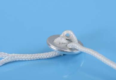


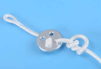
35 8. Installation 8.2. Securing closing loop Variation 1 Variation
 Complete the form in the Manual, provide a detailed description of the event (activation)")
36 9. Maintenance 9.1. Cutter replacement If the m 2 multi device has been activated, there are two ways to restore the device: a) Complete the form in the Manual, provide a detailed description of the event (activation) and send the form along with the m 2 multi device to the address of either the manufacturer MarS a.s. or any authorized dealer to perform an overall analysis. In such case the cutter will be replaced by the manufacturer or authorized dealer and the functional device will be sent back to the user within 14 day of having received the device. b) Cutter replacement performed by the user or rigger. When replacing the cutter it is always necessary to work with the device turned off; work in a clean and dry environment and follow the instructions below. Use TORX T8 screwdriver to loosen and remove the locking screw (2) securing the cutter (7) connector (1) to the m 2 multi device body (4). Gently pull and turn the connector (1) in any direction and remove it completely. Make sure that the connecting area on the m 2 multi body (4) is free of dirt and that the old sealing o-ring that was a part of the original connector (1) is removed. Lubricate the o-rings of the new cutter connector (7) (use any silicone gel, including the silicone used to treat the reserve parachute closing loop, - ATTENTION! - apply only a thin layer of the silicone) and check that both o-rings are undamaged and properly placed on the connector. Insert the new cutter (7) connector (1) into the m 2 multi device body (4) by gently pressing and turning the connector (1) in any direction until the connector (1) is completely inserted in the m 2 multi device body (4). Switch on the device to check proper function. If everything works properly, secure the cutter (7) connector (1) to the device body (4) by the locking screw (2). Tighten the screw only slightly. Never use excessive force if you experience a problem loosening the screw. Cool the device in the freezer, the contraction and expansion of various materials will help to loosen the screw. Never dispose of the used cutter in open fire or common waste. The cutter remains under pressure! 36

.")
 and regardless of any damage to the filter, pull the old filter (6) out of the device body (4).")
37 9. Maintenance 9.2. Filter replacement After contact with water, it is necessary to replace the air filter built into the m 2 multi device body. The filter serves as a barrier providing protection against contamination. Never use or store the m 2 multi device without a filter. In case the device gets into contact with water, it is necessary to perform the following: - Immediately switch off the device and remove it from the parachute kit container. - Rinse the whole device including the cables several times in clean lukewarm water. - Dry the device, and hang it by its metal body (4). - Let the cables (3 and 5) hang loose and allow the device to dry completely in the air. - Remove the old plastic filter (6), use a small screwdriver or pliers. Insert the screwdriver directly into the center of the filter (6) and regardless of any damage to the filter, pull the old filter (6) out of the device body (4). - Check the filter are (6) for impurities, and if clean insert a new filter (6). It is necessary to insert the filter (6) completely - apply great pressure to hide the filter body inside the m 2 multi device body (4). Only the filter intake tube can protrude outside the device body. - Switch on the device and check its function. - Dispose of the used filter in common waste or recycle it together with plastic waste. After any contact of the m 2 multi device with water (or any other liquid), it is always necessary to replace the filter even though the device appears to be functioning properly when dry. 37
38 9. Maintenance 9.3. Battery The m 2 multi device is designed to last its whole service life without the need to replace battery. If for any reason the battery fails, it must by replaced by the manufacturer. In case the battery indicates for example 1 % remaining, there is no need to worry, there is still enough reserve power. 100 % is displayed only the first time the m 2 multi is switched on by the manufacturer. However, if the Bat LO indication appears during calibration and the battery is down to 0 %, do not use the device! 9.4. Annual inspection The m 2 multi device must undergo a periodic inspection at least once every 12 months; the inspection is usually performed by the rigger when repacking the reserve parachute. The inspection shall be recorded in the device Technical Log. The user is always responsible for performing this inspection and it depends on him whether he performs the required activities himself or whether he has someone else do it Inspection procedure a) Inspect the device visually for any visible mechanical damage, pay special attention to the connection cables, filter, control unit and cutter. b) Check the battery (under the letter b in the device INFO menu, Section 5.4.) c) Check displayed pressure (under the letter P in the device INFO menu, Section 5.4.) Perform the pressure check by comparing it to another precision instrument that shows barometric pressure. It is also possible to use the actual pressure at the airport. The deviation shall not be greater than +/-15 hpa. 38
39 10. Technical data Basic technical data Total weight... approx. 220g Length, width, height of the processing unit... approx. 85mm x 45mm x 23mm Length, width, height of the control unit... approx. 63mm x 18mm x 5mm Thickness, length of the cutting unit... thickness 8mm x length 55mm Control unit cable length... approx. 660mm Cutting unit cable length... approx. 500mm Working temperature (inside the device)... approx. from -20 C / -4 F to +60 C / +140 F Storage temperature - recommended... approx. from +5 C / +41 F to +25 C / +77 F Water resistance hours up to 2m / 6.5ft deep Adjusting landing location altitude... approx. +/- 999m / +/- 2,999ft Operation time... approx. 14 hours from activation Total service life... approx. 15 years + 6 months or flight hours or jumps (20 minutes per jump) Range of use under / above sea level... approx. -500m / -1,640ft to m / +26,200ft Device service life The total service life of the m 2 multi device is 15 years + 6 months from the date of manufacture, or a total of about flight hours, which is about jumps (maximum 20 minutes per jump start-landing). After the final assembly and complete operation test of each m 2 multi device, the device remains fully functional, including actual deduction of the battery capacity. If during a battery check, a new m 2 multi device displays the current capacity 99 % (INFO, letter b, Section 5.4.), the number is correct and DOES NOT IN ANY WAY AFFECT THE GIVEN TOTAL SERVICE LIFE of the m 2 multi device. For a quick and easy check, the device can show the current capacity in %. As long as the capacity is higher than 0 %, the device will always provide reliable function. In case the capacity drops to zero, the device displays a flashing letter b (battery) when switched on during calibration. However, the device will still be functional. Never use the m 2 multi device with 0% battery capacity! Cutter service life The cutter service life is 16 years from the date of manufacture. The cutter is marked with the batch code and the last two digits of the year of manufacture. Never use an expired cutter Warranty The manufacturer grants a warranty of 24 months from the date of purchase on all parts used in the m 2 multi device and its proper operation within the specified limits. The warranty does not cover damage resulting from normal use of the device, its improper installation or non-standard and rough handling. The manufacturer reserves the right to decide whether to repair or replace the device. 39
40 11. Disclaimer MarS a.s. dedicated great care and attention to the development, laboratory testing, field testing and to the m 2 multi device properties. The goal was and still is to provide users with maximum comfort and safety when using the automatic activation device. All our efforts are directed to the cutter reliability when cutting the reserve parachute closing loop when its activation criteria are met. Although the device will work properly, it does not guarantee the functionality of the other parts of the parachute kit. The device itself does not exclude the possibility of severe injury or even death. The device is only one of the ways to increase the likelihood of resolving a critical situation the user may find himself in when skydiving. Never rely solely on the automatic activation device. The basis for safe jumps are quality training, appropriate health condition, mental abilities, quality equipment for performing jumps from authorized manufacturers and familiarization with the procedures of dealing with an emergency. Only when these conditions are met, the automatic activation device may help to increase the likelihood of resolving an emergency, if such occurs. The automatic activation device (AAD) is an electronic device and as such may not always work properly even when installed and used properly. Using the appliance only reduces the risk of injury or even death of its user. Shall the user still choose to use the device or provide the device to be used by another person, this act confirms that he is aware of these risks and consequences associated with the use of this device. Even when properly used, the device may cause serious injury or death! by using this device, the user commits to use it as described in this Manual. The manufacturer assumes no liability for damages resulting from non-compliance with the determined procedures. The manufacturer, MarS a.s assumes no responsibility for any failures and any resulting damage or consequences. If the user is not willing to accept these facts, the manufacturer recommends he does not use the device. 40
 may be different depending on the parachute container.")

41 12. Appendices X-RAY Card To Airport Security Personnel: The device m 2 multi is a parachute emergency opening system for reserve parachute. The m 2 multi is a life saving device for skydivers. Display on the screen (X-ray) may be different depending on the parachute container. All parts of device are not subject to any transport regulations. The m 2 multi parts: 1. central unit, 2. control unit, 3. cutter, 4. control unit cable, 5. cutter cable X-ray card Packed in a box MarS a.s., Okruzni II Jevicko, Czech Republic mars@marsjev.cz phone
The Military CYPRES Quick Guide For Operators
 The Military CYPRES Quick Guide For Operators The military CYPRES is available in the following standard models: All models can be adapted with a one or two-pin cutter. 1000/35 A 1500/35 A 1000/35 indicates
ECHO MANUAL WARNING. L B A ltim e te rs. ECHO is a trademark of LB Altimeters, Denmark
 ECHO MANUAL L B A ltim e te rs ECHO is a trademark of LB Altimeters, Denmark LB Altimeters operates a policy of continuous development Therefore, we reserve the right to make changes and improvements to
Manufactured by: AAA
 Manufactured by: AAA The Altitron Skydiving Altimeter is an advanced digital altimeter. It is designed to effectively improve safety and easily keep track of skydiving activity. It can be used as a mechanical
Vigil II User s Manual
 Multimode A.A.D. NATO Stock Number (NSN) 1377-13-119-7112 Vigil II User s Manual US v II.0.1 The Vigil is endorsed by: AAD NV/SA. Advanced Aerospace Designs Boulevard A. Reyers 193 B-1030 Brussels Belgium
A.A.D. English. Upgraded Vigil II Multimode User's Manual US v
 A.A.D. English 1 Upgraded Vigil II Multimode User's Manual US v2017.09.22 Vigil II Multimode Your Vigil II Multimode with SN SN #9397 #SNNR# with DOM 44/07 #DO# (week/ year) has been upgraded with firmware
Multifunction Altimeter/Variometer AV1
 Multifunction Altimeter/Variometer AV1 Revision#3.0, 21/11/2014 For firmware version 2.2 Page intentionally left blank SECTIONS MECHANICAL INSTALLATION ELECTRICAL INSTALLATION USE OF THE INSTRUMENT INSTRUMENT
Multimode. User s Manual. US v2.0.5
 Multimode User s Manual US v2.0.5 The Vigil is endorsed by: AAD nv/sa. Advanced Aerospace Designs Boulevard A. Reyers 193 B-1030 Brussels Belgium : +32 (0)2 732 65 52 F: +32 (0)2 736 06 27 e-mail: info@vigil.aero
MicroTim XB. User Manual. Precision Digital Barometric Altimeter / Barometer / VSI. Document Revision 1.0 Firmware Version 3.0
 MicroTim XB Precision Digital Barometric Altimeter / Barometer / VSI User Manual Document Revision 1.0 Firmware Version 3.0 Table of Contents Table of Contents...2 1 General Operation...5 1.1 Altitude
VISO Manual. LARSEN & BRUSGAARD Mosevej Kirke Hyllinge, Denmark Phone: Fax:
 VISO Manual LARSEN & BRUSGAARD Mosevej 3 4070 Kirke Hyllinge, Denmark Phone: +45 4648 2480 Fax: +45 4648 2490 E-mail: L-and-B@L-and-B.dk WARNING! FAILURE TO FOLLOW ALL WARNINGS, INSTRUCTIONS, AND REQUIRED
WARNING! Jump Number Main Window Exit Altitude Alti-Meter Mode Deployment Altitude Speed-Meter Mode...
 VISO II Manual LARSEN & BRUSGAARD Mosevej 3 4070 Kirke Hyllinge, Denmark Phone: +45 4648 2480 Fax: +45 4648 2490 E-mail: L-and-B@L-and-B.dk WARNING! FAILURE TO FOLLOW ALL WARNINGS, INSTRUCTIONS, AND REQUIRED
Multimode. User s Manual. US v2.0.7
 Multimode User s Manual US v2.0.7 The Vigil is endorsed by: AAD nv/sa. Advanced Aerospace Designs Boulevard A. Reyers 193 B-1030 Brussels Belgium : +32 (0)2 732 65 52 F: +32 (0)2 736 06 27 e-mail: info@vigil.aero
WARNING! FAILURE TO FOLLOW ALL WARNINGS, INSTRUCTIONS, AND REQUIRED PROCEDURES MAY RESULT IN SERIOUS INJURY AND DEATH.
 PROTRACK II Manual Every technical device can fail. So everything imaginable can happen with the PROTRACK II, including, but not limited to: displaying a status which is not true, failing to function,
PROPORTIONING VALVE. Model 150 INSTRUCTION MANUAL. March 2017 IMS Company Stafford Road
 PROPORTIONING VALVE Model 150 INSTRUCTION MANUAL March 2017 IMS Company 10373 Stafford Road Telephone: (440) 543-1615 Fax: (440) 543-1069 Email: sales@imscompany.com 1 Introduction IMS Company reserves
DEH Instructions. Three-Phase, Platform-Mounted Distribution Transformers
 g DEH 40050 Instructions Three-Phase, Platform-Mounted Distribution Transformers Introduction The equipment covered by these instructions should be operated and serviced only by competent technicians familiar
1.0 General Guide WARNING!
 User Manual 1.0 General Guide Thank you for purchasing your new ADC. We recommend reading this manual, and practicing the operations before using your ADC in the field. The ADC is designed to provide you
Ambient Weather GL150-B Nautical Barometer User Manual
 Ambient Weather GL150-B Nautical Barometer User Manual Table of Contents 1. Introduction... 2 2. Care and Cleaning... 2 3. Installation... 2 4. Barometer Operation... 3 3.1 How the aneroid barometer works...
Leg Pouch Pilot Chute System
 Leg Pouch Pilot Chute System User Manual Version 1 Sep 2008 Page 1 Disclaimer: The following information must be read and understood before any use of this equipment. The user knows the risks of skydiving
Butler Parachute Systems, Inc
 Butler Parachute Systems, Inc A division of Butler Parachute Systems Group, Inc. TT-600 GEN 1 & 2 TETHERED TANDEM BUNDLE DELIVERY SYSTEM ASSEMBLY MANUAL 1 JUN 2010 INTRODUCTION This manual contains all
Manufactured by: Mosevej Kirke Hyllinge, Denmark Phone: Fax:
 MANUAL AL Manufactured by: Mosevej 3 4070 Kirke Hyllinge, Denmark Phone: +46 40 44 05 Fax: +46 75 77 22 e-mail: dytter@pip.dknet.dk PRO-TRACK is a trademark of Larsen & Brusgaard, Denmark. 1999. Larsen
Technical Data Sheet MF010-O-LC
 Technical Data Sheet MF010-O-LC - 1 - 1. Properties The oxygen measuring system MF010-O-LC determines the oxygen content in gas mixtures up to a temperature of 250 C. It is particularly suitable for the
WIND CLIPPER KTS ILLUM SCALE INC DEC CLIPPER WIND SYSTEM
 CLIPPER WIND KTS ILLUM SCALE DEC INC CLIPPER WIND SYSTEM TABLE OF CONTENTS INTRODUCTION PRE-TEST OF INSTRUMENT INSTALLING THE MASTHEAD SENSOR UNIT INSTALLING THE DISPLAY NORMAL OPERATION CHANGING THE
USPA National Speed Skydiving Championships Competition Rules. Chapter 14. United States Parachute Association Copyright 2018 by USPA
 USPA National Speed Skydiving Championships Competition Rules Chapter 14 United States Parachute Association Copyright 2018 by USPA USPA AUTHORITY The competition will be conducted under the authority
Copyright 2004 by the Thomas G. Faria Corporation, Uncasville CT No part of this publication may by reproduced in any form, in an electronic
 Copyright 2004 by the Thomas G. Faria Corporation, Uncasville CT No part of this publication may by reproduced in any form, in an electronic retrieval system or otherwise, without the prior written permission
Bante810 Benchtop Dissolved Oxygen Meter Instruction Manual
 Bante810 Benchtop Dissolved Oxygen Meter Instruction Manual BANTE INSTRUMENTS CO., LTD Bante810 Benchtop Dissolved Oxygen Meter 1 Introduction Thank you for selecting the Bante810 benchtop dissolved oxygen
HUNTER Beeper Collar Manual
 HUNTER 2000- Beeper Collar Manual For a better performance: Use only Duracell batteries Each adjustment affects the duration of the batteries The battery contacts must be kept clean The thread of the Beeper
Altimeter and Compass Watch Instruction Manual
 Altimeter and Compass Watch Instruction Manual Overview Figure 1 LCD display description Features Hour, minute, second, year, Auto calendar 12/24 hour format display month, day, day of week Daily alarm
DBI version 002 User Manual US version Free Balloon Flight Instrument
 DBI version 002 User Manual US version Free Balloon Flight Instrument DBI 002 User Manual issue C7, 2005-05-25 Page 1/29 Safety The manufacturer has designed this instrument to be safe when operated. Do
3) The proper Exit procedures have been taught. I have practiced them and can perform as required. Please initial here:
 The proper Exit procedures have been taught. I have practiced them and can perform as required. Please initial here:") SKYDIVE CITY - FJC Exam for AFF Students STUDENT'S NAME Date INSTRUCTOR'S NAME Location By the following, I certify that I have been trained in the following aspects of parachuting and that I know and
SKYDIVE CITY - FJC Exam for AFF Students STUDENT'S NAME Date INSTRUCTOR'S NAME Location By the following, I certify that I have been trained in the following aspects of parachuting and that I know and
Butler Tactical Parachute Systems, LLC
 Butler Tactical Parachute Systems, LLC A division of Butler Parachute Systems Group, Inc. TT-600 TETHERED TANDEM BUNDLE DELIVERY SYSTEM PACKING MANUAL (REVISION A ) Page 1 of 62 INTRODUCTION This manual
User Manual 1 P a g e Rev. V1.6-EN 11/08/2014
 User Manual 1 P a g e Rev. V1.6-EN 11/08/2014 Copyright Disclaimer Trademarks and patents Intended use Contact info 2011 Inflotrolix, Inc. This document may not be copied in whole or in part or otherwise
2018 Skydiver s Information Manual Summary of Changes
 Table of Contents SECTION 2 BASIC SAFETY REQUIREMENTS AND WAIVERS 3 2-1 BASIC SAFETY REQUIREMENTS 3 C. MEDICAL REQUIREMENTS 3 E. MEMBERSHIP 3 F. ALCOHOL AND DRUGS 3 G. STUDENT SKYDIVERS 3 H. WINDS [S]
DT 630 ALTIMETER, BAROMETER AND COMPASS WATCH OPERATING INSTRUSTIONS
 DT 630 ALTIMETER, BAROMETER AND COMPASS WATCH OPERATING INSTRUSTIONS Overview:--- Positive or Negative Icon Barometric Trend Indicator SELECT Low Battery Indicator AM/FM Indicator Daily Alarm Indicator
User's Manual. Heavy Duty Dissolved Oxygen Meter. Model
 User's Manual Heavy Duty Dissolved Oxygen Meter Model 407510 Introduction Congratulations on your purchase of Extech's Heavy Duty Dissolved Oxygen / Temperature Meter which simultaneously displays Dissolved
Bante820 Portable Dissolved Oxygen Meter Instruction Manual
 Bante820 Portable Dissolved Oxygen Meter Instruction Manual BANTE INSTRUMENTS CO., LTD Bante820 Portable Dissolved Oxygen Meter 1 Introduction Thank you for selecting the Bante820 portable dissolved oxygen
A4s Operation Manual
 A4s Operation Manual Safety Instruction Please read this manual carefully, also with related manual for the machinery before use the controller. For installing and operating the controller properly and
CYPRES 2 Military User s Guide - English version -
 CYPRES CYPRES CYPRES 2 Military User s Guide - English version - Congratulations on your choice of CYPRES, the safest and most accurate AAD currently available. Like most parachutists, you probably assume
OPERATOR S MANUAL Ar-Gone Weld Gas Analyzer
 July 2011 OPERATOR S MANUAL Ar-Gone Weld Gas Analyzer WARNING! Before operating this product, read and understand this Operator s Manual. Become familiar with the potential hazards of this unit. Contact
MJB4 Mask Aligner Operating Procedure. Effective Date: 07/12/2012 Author(s): Jiong Hua Phone:
: Jiong Hua Phone:") MJB4 Mask Aligner Operating Procedure Effective Date: 07/12/2012 Author(s): Jiong Hua Phone: 402-472-3773 Email: jhua2@unl.edu 1 1 Introduction 1.1 Key Words Karl Suss MJB4 Mask Aligner, Optical Lithography,
MJB4 Mask Aligner Operating Procedure Effective Date: 07/12/2012 Author(s): Jiong Hua Phone: 402-472-3773 Email: jhua2@unl.edu 1 1 Introduction 1.1 Key Words Karl Suss MJB4 Mask Aligner, Optical Lithography,
OPERATION. Estimated kerf width compensation. HPR260 Manual Gas Instruction Manual 4-9
 Estimated kerf width compensation The widths in the chart below are for reference. Differences between installations and material composition may cause the specific user results to vary from those shown
Type BBS-03, BBS-05, BBS-06, BBS-25
 Type BBS-03, BBS-05, BBS-06, BBS-25 Sterile connection elements Sterile Verbindungselemente Raccords union stériles Operating Instructions Bedienungsanleitung Manuel d utilisation 1. THE OPERATING INSTRUCTIONS
Alcotest Breath Alcohol Screening Device. Operator Instructions for Use. ST _sw.eps
 D Alcotest 6510 Breath Alcohol Screening Device Operator Instructions for Use ST-207-2004_sw.eps Contents Contents................................................. 2 For your safety............................................
SUPPLEMENT TO AIRCRAFT FLIGHT MANUAL FOR MOTOR-DRIVEN ROPE WINCH TYPE RPM 11/01
 SUPPLEMENT TO AIRCRAFT FLIGHT MANUAL FOR MOTOR-DRIVEN ROPE WINCH TYPE RPM 11/01 (Langenthaler-Winch) Aircraft-Manufacturer: Avions Robin SA Type of Aircraft: Robin DR 300-180R DR400-180R DR 400-200R DR
G2W PRO ROBOT. User Manual. paddlepalace.com
 G2W PRO ROBOT paddlepalace.com 1-800-547-5891 503-777-2266 Putting Robot Technology to Work for You The Paddle Palace G2W Pro robot is everything you need in a robot! This robot has two throw wheels with
CDS-2000 CO 2 Sensor Verification, Calibration, and Troubleshooting Bulletin
 Electronic Control Manual 216 Sensors and Stats Section S Technical Bulletin CDS-2000 Issue Date 0393 CDS-2000 CO 2 Sensor Verification, Calibration, and Troubleshooting Bulletin Introduction 3 Pre-Verification
Table of contents. Table of contents 1. Installation 2. Introduction ( Display, monitor ) 3. Introduction ( Operating elements ) 4
 3. Introduction ( Operating elements ) 4") Table of contents page 1 CONTENTS PAGE Table of contents 1 Installation 2 Introduction ( Display, monitor ) 3 Introduction ( Operating elements ) 4 Introduction ( Result interpretation) 5 Factory default
Table of contents page 1 CONTENTS PAGE Table of contents 1 Installation 2 Introduction ( Display, monitor ) 3 Introduction ( Operating elements ) 4 Introduction ( Result interpretation) 5 Factory default
New product release. Universal Rebreather Monitor (URBM) Three cell / Independent backup
 Three cell / Independent backup") New product release Closed Circuit Research is pleased to announce the launch of our range of Universal Rebreather Monitors Universal Rebreather Monitor (URBM) Three cell / Independent backup Key features
New product release Closed Circuit Research is pleased to announce the launch of our range of Universal Rebreather Monitors Universal Rebreather Monitor (URBM) Three cell / Independent backup Key features
Operator's Manual Supplement
 Operator's Manual Supplement Cribbing Instructions First Edition Sixth Printing Part No. 82943GT Operator's Manual Supplement Front Matter Important Contents Plywood cribbing may be used to provide a level
Aircrew CYPRES 2 User s Guide - english version -
 CYPRES Aircrew CYPRES 2 User s Guide - english version - Congratulations on your choice of CYPRES, the surely safest and most accurate Automatic Activation Device currently available. Like most airmen,
Victoreen B. Operators Manual. Image Intensifier Ion Chamber
 Victoreen 6000-530B Image Intensifier Ion Chamber Operators Manual March 2005 Manual No 6000-530B-1 Rev. 4 2004, 2005 Fluke Corporation, All rights reserved. All product names are trademarks of their respective
400C & 450C DUAL PERFORMANCE VALUE PACKS
 (Chrome) PART NO. 40013 (Silver) PART NO. 45012 (Chrome) PART NO. 45013 IMPORTANT: It is essential that you and any other operator of this product read and understand the contents of this manual before
5 Function Indicator. Outside Air Temperature (C) Outside Air Temperature (F) Pressure Altitude Density Altitude Aircraft Voltage STD TEMP SL 15000
 Outside Air Temperature (F) Pressure Altitude Density Altitude Aircraft Voltage STD TEMP SL 15000") 5 Function Indicator +20 +40-5000 STD TEMP SL 15000 Outside Air Temperature (C) Outside Air Temperature (F) Pressure Altitude Density Altitude Aircraft Voltage 427 HILLCREST WAY REDWOOD CITY, CA 94062
5 Function Indicator +20 +40-5000 STD TEMP SL 15000 Outside Air Temperature (C) Outside Air Temperature (F) Pressure Altitude Density Altitude Aircraft Voltage 427 HILLCREST WAY REDWOOD CITY, CA 94062
42045 Heavy Duty ADA Base Model Kit: 85/105 PSI (ADA Compressor Only) Heavy Duty ADA Base Model Kit: 110/145 PSI (ADA Compressor Only)
 Heavy Duty ADA Base Model Kit: 110/145 PSI (ADA Compressor Only)") 42045 Heavy Duty ADA Base Model Kit: 85/105 PSI (ADA Compressor Only) 42047 Heavy Duty ADA Base Model Kit: 110/145 PSI (ADA Compressor Only) 45052 Constant Duty ADA Base Model Kit: 85/105 PSI (ADA Compressor
42045 Heavy Duty ADA Base Model Kit: 85/105 PSI (ADA Compressor Only) 42047 Heavy Duty ADA Base Model Kit: 110/145 PSI (ADA Compressor Only) 45052 Constant Duty ADA Base Model Kit: 85/105 PSI (ADA Compressor
ORRA SPINNING REEL INSTRUCTION MANUAL (DRAFT)
") ORRA SPINNING REEL INSTRUCTION MANUAL (DRAFT) a. Congratulations b. Pictures of Components c. Family Info d. How to Fill the Spool with Line e. Handle Assembly f. Anti-Reverse g. Drag Adjustment h. Reel
ORRA SPINNING REEL INSTRUCTION MANUAL (DRAFT) a. Congratulations b. Pictures of Components c. Family Info d. How to Fill the Spool with Line e. Handle Assembly f. Anti-Reverse g. Drag Adjustment h. Reel
OXY Integral. INTERCON ENTERPRISES INC Tel: Fax: Internet:
 OXY Integral INTERCON ENTERPRISES INC Tel: 800 665 6655 Fax: 604 946 5340 E-Mail: sales@intercononline.com Internet: www.intercononline.com Manual Integral 2006 1 INDEX 2-3 PREFACE 4 INTRODUCTION 5 Principle
Safety Manual. Process pressure transmitter IPT-1* 4 20 ma/hart. Process pressure transmitter IPT-1*
 Safety Manual Process pressure transmitter IPT-1* 4 20 ma/hart Process pressure transmitter IPT-1* Contents Contents 1 Functional safety 1.1 General information... 3 1.2 Planning... 4 1.3 Instrument parameter
200 PSI COMPRESSORS - MODEL NUMBERS
 200 PSI COMPRESSORS - MODEL NUMBERS 380C AIR COMPRESSOR KIT PART NO. 38033 480C AIR COMPRESSOR KIT PART NO. 48043 380C 480C IMPORTANT: It is essential that you and any other operator of this product read
DOscan10 Pocket Dissolved Oxygen Tester Instruction Manual
 DOscan10 Pocket Dissolved Oxygen Tester Instruction Manual BANTE INSTRUMENTS CO., LTD DOscan10 Pocket Dissolved Oxygen Tester 1 Thank you for selecting the DOscan10 pocket dissolved oxygen tester. This
A4 Operation Manual. Fig.1-1 Controller Socket Diagram
 A4 Operation Manual Safety Instruction Please read this manual carefully, also with related manual for the machinery before use the controller. For installing and operating the controller properly and
T i m i n g S y s t e m s. RACEAMERICA, Inc. P.O. Box 3469 Santa Clara, CA (408)
") RACEAMERICA T i m i n g S y s t e m s Demo Tree Controller Owner s Manual Models 3204D, 3204DW & 3204DX Rev D RACEAMERICA, Inc. P.O. Box 3469 Santa Clara, CA 95055-3469 (408) 988-6188 http://www.raceamerica.com
RACEAMERICA T i m i n g S y s t e m s Demo Tree Controller Owner s Manual Models 3204D, 3204DW & 3204DX Rev D RACEAMERICA, Inc. P.O. Box 3469 Santa Clara, CA 95055-3469 (408) 988-6188 http://www.raceamerica.com
alphabelt Holding & Rescue Belt Revolutionary Safe Gear to Restrain and Rescue Yourself
 alphabelt Holding & Rescue Belt Revolutionary Safe Gear to Restrain and Rescue Yourself Because every life has a purpose... alphabelt A Revolution in Safety Previous fall protection solutions, like firefighter
97C COMPRESSOR KIT 12V PART NO C COMPRESSOR KIT 24V PART NO C COMPRESSOR KIT PART NO
 97C COMPRESSOR KIT 12V PART NO. 00097 97C COMPRESSOR KIT 24V PART NO. 02497 98C COMPRESSOR KIT PART NO. 00098 97C 98C IMPORTANT: It is essential that you and any other operator of this product read and
DM-RAPD (English) Dealer's Manual. ROAD MTB Trekking. City Touring/ Comfort Bike. SPD-SL Pedal DURA-ACE PD-R9100 ULTEGRA PD-R8000 SM-PD63
 Dealer's Manual. ROAD MTB Trekking. City Touring/ Comfort Bike. SPD-SL Pedal DURA-ACE PD-R9100 ULTEGRA PD-R8000 SM-PD63") (English) DM-RAPD001-01 Dealer's Manual ROAD MTB Trekking City Touring/ Comfort Bike URBAN SPORT E-BIKE SPD-SL Pedal DURA-ACE PD-R9100 ULTEGRA PD-R8000 SM-PD63 CONTENTS IMPORTANT NOTICE... 3 TO ENSURE
(English) DM-RAPD001-01 Dealer's Manual ROAD MTB Trekking City Touring/ Comfort Bike URBAN SPORT E-BIKE SPD-SL Pedal DURA-ACE PD-R9100 ULTEGRA PD-R8000 SM-PD63 CONTENTS IMPORTANT NOTICE... 3 TO ENSURE
ASTRA AUTOMATIC ACTIVATION DEVICE (AAD)
") ASTRA AUTOMATIC ACTIVATION DEVICE (AAD) Contents ASTRA Advantages Design Concepts Function ASTRA Components Operation of the ASTRA Calibration of the ASTRA Typical Installation Theory of Operation Maintenance
ASTRA AUTOMATIC ACTIVATION DEVICE (AAD) Contents ASTRA Advantages Design Concepts Function ASTRA Components Operation of the ASTRA Calibration of the ASTRA Typical Installation Theory of Operation Maintenance
Approved Models. Important. Contents
 Cribbing Instructions First Edition Fifth Printing Important Plywood cribbing may be used to provide a level surface for safe boom operation. This instruction manual contains specifications for site constructed
Thumb Shifter Plus Thumb Shifter
 (English) DM-SL0004-01 Dealer's Manual Thumb Shifter Plus Thumb Shifter Thumb Shifter Plus SL-FT55 SL-TX50 SL-TX30 Thumb Shifter SL-TZ20 IMPORTANT NOTICE This dealer's manual is intended primarily for
S4W PRO ROBOT. User Manual. paddlepalace.com
 S4W PRO ROBOT paddlepalace.com 800-547-5891 503-777-2266 S4W Pro Taking Robot Technology to the Next Level The Paddle Palace S4W Pro takes robot technology to the next level. This innovative robot has
Operating Instructions for BAIR22-6 AIR-POWERED CRIMPING TOOL
 Operating Instructions for BAIR22-6 AIR-POWERED CRIMPING TOOL Read and understand all of the instructions and safety information in this manual before operating or servicing this tool. Table of Contents
TANK MANAGER FOR TWO TANKS OPERATING MANUAL. 10/31/11 C-More T6C L color touch panel
 TANK MANAGER FOR TWO TANKS OPERATING MANUAL 10/31/11 C-More T6C L color touch panel 1 TABLE OF CONTENTS GENERAL...3 INSTALLATION...4 STONE TEST PROCEDURE...7 OPERATIONAL SUMMARY...7 AUTO CARBONATION...10
Competition Rules. For Speed Skydiving
 Competition Rules For Speed Skydiving Effective 1 March 2017 FEDERATION AERONAUTIQUE INTERNATIONALE MSI - Avenue de Rhodanie 54 CH-1007 Lausanne Switzerland Copyright 2017 All rights reserved. Copyright
AA100 Acoustic Actuator
 AA100 Acoustic Actuator Operating Manual REV. A, September 2001 COPYRIGHT 2001. ALL RIGHTS RESERVED Return Procedure It is necessary to obtain from ORE Offshore a Returned Material Evaluation (RMA) number
MODEL NUMBER: PSI AIR SOURCE KIT 200 PSI Compressor on 2.0 Gallon 200 PSI Air Tank
 IMPORTANT SAFETY INSTRUCTIONS CAUTION - To reduce risk of electrical shock or Electrocution: MODEL NUMBER: 20008 200 PSI AIR SOURCE KIT 200 PSI Compressor on 2.0 Gallon 200 PSI Air Tank IMPORTANT: It is
ALERT SERVICE LETTER
 Citation TITLE ALERT SERVICE LETTER ASL750-35-04 OXYGEN - TRANSMITTAL OF AVOX SYSTEMS SERVICE INSTRUCTION 833-35-01 REVISION D, REPACKING PROCEDURES FOR 289 PASSENGER OXYGEN MASKS EFFECTIVITY MODEL SERIAL
Cantilever Brake. Dealer's Manual. ROAD MTB Trekking. City Touring/ Comfort Bike
 (English) DM-RCBR001-00 Dealer's Manual ROAD MTB Trekking City Touring/ Comfort Bike URBAN SPORT E-BIKE Cantilever Brake BR-CX70 BR-CX50 BL-4700 BL-4600 BL-R780 BL-R3000 ST-7900 ST-6700 ST-5700 ST-4600
444C DUAL PERFORMANCE VALUE PACK
 (Chrome) PART NO. 44432 IMPORTANT: It is essential that you and any other operator of this product read and understand the contents of this manual before installing and using this product. SAVE THIS MANUAL
OC Panel High Limit Aquastat Kit, Manual Reset p/n
 OC Panel High Limit Aquastat Kit, Manual Reset p/n 233202 Instruction Sheet APPLICATION The OC (Option Control) Panel High Limit Aquastat Kit provides electronic temperature sensing in a UL limit-rated
Superconducting Susceptometer (MPMS-5S) Quantum Design Room 296 (MPMS)
 Quantum Design Room 296 (MPMS)") Superconducting Susceptometer (MPMS-5S) Quantum Design Room 296 (MPMS) Sensitivity: 1x10 11 A m 2 Applied DC fields: 0 T to 5 T Applied AC fields: 0 G to 3 G (zero-to-peak), 0.01 Hz to 1000 Hz Temperatures
Superconducting Susceptometer (MPMS-5S) Quantum Design Room 296 (MPMS) Sensitivity: 1x10 11 A m 2 Applied DC fields: 0 T to 5 T Applied AC fields: 0 G to 3 G (zero-to-peak), 0.01 Hz to 1000 Hz Temperatures
OxyScan Graphic. Operating Instructions. UMS Micro-oxygen sensor 501. Microprocessor instrument
 OxyScan Graphic Operating Instructions UMS Micro-oxygen sensor 501 Microprocessor instrument Introduction Thank you for choosing the UMS Micro Oxygen Sensor 501 - a highly advanced product! Please read
IMPORTANT SAFETY INSTRUCTIONS
 IMPORTANT SAFETY INSTRUCTIONS CAUTION - To reduce risk of electrical shock: - Do not disassemble. Do not attempt repairs or modifications. Refer to qualified service agencies for all service and repairs.
420C AIR COMPRESSOR KIT PART NO C AIR COMPRESSOR KIT PART NO
 420C AIR COMPRESSOR KIT PART NO. 42042 460C AIR COMPRESSOR KIT PART NO. 46043 420C 460C IMPORTANT: It is essential that you and any other operator of this product read and understand the contents of this
LOAD CHARTS RT890E METRIC DIN / ISO / 75%
 LOAD CHARTS RT89E METRIC DIN / ISO / 75% 232729 SERIAL NUMBER RT89E - S/N 232729 1 RT89E - S/N 232729 2 TABLE OF CONTENTS GENERAL NOTES...4 WEIGHT REDUCTIONS / LINE PULLS & REEVING INFO / RIGGING CHART
MODEL NUMBER: M20005 AIR SOURCE KIT. 30% Duty Compressor on. 2.0 Gallon Air Tank SAVE THIS MANUAL FOR FUTURE REFERENCE
 MODEL NUMBER: M20005 AIR SOURCE KIT 30% Duty Compressor on 2.0 Gallon Air Tank SAVE THIS MANUAL FOR FUTURE REFERENCE USER MANUAL IMPORTANT SAFETY INSTRUCTIONS CAUTION - To reduce risk of electrical shock
D OPERATION and MAINTENANCE MANUAL MILITARY ALTIMASTER MA-10 (12,000 foot LINEAR SCALE: FP-02096) April 8, 2013 REV L
 April 8, 2013 REV L") D-90073 OPERATION and MAINTENANCE MANUAL MILITARY ALTIMASTER MA-10 (12,000 foot LINEAR SCALE: FP-02096) April 8, 2013 REV L ALTI-2 PROPRIETARY Page 1 of 15 TABLE OF CONTENTS DESCRIPTION... 3 SPECIFICATION...
D-90073 OPERATION and MAINTENANCE MANUAL MILITARY ALTIMASTER MA-10 (12,000 foot LINEAR SCALE: FP-02096) April 8, 2013 REV L ALTI-2 PROPRIETARY Page 1 of 15 TABLE OF CONTENTS DESCRIPTION... 3 SPECIFICATION...
CONTENTS SPECIFICATIONS GENERAL INFORMATION RECOMMENDED USE OPERATING PRINCIPLE TIPS ON TAKING YOUR BLOOD PRESSURE 3-4 BATTERY INSTALLATION
 IFU SBPMON107 CONTENTS SPECIFICATIONS GENERAL INFORMATION RECOMMENDED USE OPERATING PRINCIPLE TIPS ON TAKING YOUR BLOOD PRESSURE BATTERY INSTALLATION CORRECT POSITION FOR MEASUREMENT POSITIONING THE CUFF
Installation and Operation Manual
 Manual Static pressure transducer with controller Differential static pressure transducer with analog output and optional PI control mode Large diaphragm element with differential transformer Transducer
9A5N Solid State CW Paddle
 9A5N Solid State CW Paddle User manual Table of contents: 1. General description 2. Before you begin 3. Finger piece and/or battery installation 4. Interconnection 5. Lever(s) sensitivity adjustment 6.
Model Visit our website at:
 6 DIAL Fractional CALIPER Model 92437 Set up And Operating Instructions Visit our website at: http://www.harborfreight.com Read this material before using this product. Failure to do so can result in serious
250C-IG COMPRESSOR KIT 12V PART NO C-IG COMPRESSOR KIT 24V PART NO
 250C-IG COMPRESSOR KIT 12V PART NO. 25050 250C-IG COMPRESSOR KIT 24V PART NO. 25058 IMPORTANT: It is essential that you and any other operator of this product read and understand the contents of this manual
Bante821 Portable Dissolved Oxygen Meter Instruction Manual
 Bante821 Portable Dissolved Oxygen Meter Instruction Manual BANTE INSTRUMENTS CO., LTD Bante821 Portable Dissolved Oxygen Meter 1 Introduction Thank you for selecting the Bante821 portable dissolved oxygen
file:///users/samuel/documents/delft/masters/4th%20year%20su... APCO AVIATION USER MANUAL High-Rise Rescue Chute
 APCO AVIATION USER MANUAL High-Rise Rescue Chute INDEX Introduction Disclaimer & Warranty Use Introduction The High-Rise Rescue Chute was developed after the tragic events of September 11 2001 in New York,
METEOR LSR36500 LIGHTING UNDERWATER POOL LIGHT. Operating Instructions
 METEOR LSR36500 UNDERWATER POOL LIGHT Operating Instructions LIGHTING CONTENTS Preface...3 Features...3 Precautions...3 Components and Connectors...4 Installation...5 Controls...7 Appearance...8 Technical
Met One E-BAM Particulate Monitor
 STANDARD OPERATING PROCEDURES Met One E-BAM Particulate Monitor AMBIENT AIR MONITORING PROGRAM for the 130 LIBERTY STREET DECONSTRUCTION PROJECT LOWER MANHATTAN DEVELOPMENT CORPORATION 1 Liberty Plaza
Scoreboard Operator s Instructions MPC Control
 Scoreboard Operator s Instructions MPC Control Some features on the keyboard overlay may not be included on the particular model being operated. Since 1934 Retain this manual in your permanent files 1/21/2011
MODEL NUMBER: P PORTABLE COMPRESSOR
 MODEL NUMBER: 44043-440P PORTABLE COMPRESSOR IMPORTANT: It is essential that you and any other operator of the product read and understand the contents of this manual before installing and using this product.
testo Leakage detector for refrigerants Instruction manual
 testo 316-3 Leakage detector for refrigerants Instruction manual 2 1 Contents 1 Contents 1 Contents... 3 2 Safety and the environment... 4 2.1. About this document... 4 2.2. Ensure safety... 4 2.3. Protecting
DM-MARD (English) Dealer's Manual. ROAD MTB Trekking. City Touring/ Comfort Bike REAR DERAILLEUR XTR RD-M9100 RD-M9120
 Dealer's Manual. ROAD MTB Trekking. City Touring/ Comfort Bike REAR DERAILLEUR XTR RD-M9100 RD-M9120") (English) DM-MARD001-00 Dealer's Manual ROAD MTB Trekking City Touring/ Comfort Bike URBAN SPORT E-BIKE REAR DERAILLEUR XTR RD-M9100 RD-M9120 CONTENTS CONTENTS...2 IMPORTANT NOTICE...3 TO ENSURE SAFETY...4
(English) DM-MARD001-00 Dealer's Manual ROAD MTB Trekking City Touring/ Comfort Bike URBAN SPORT E-BIKE REAR DERAILLEUR XTR RD-M9100 RD-M9120 CONTENTS CONTENTS...2 IMPORTANT NOTICE...3 TO ENSURE SAFETY...4
250C-IG COMPRESSOR KIT 12V PART NO C-IG COMPRESSOR KIT 24V PART NO
 250C-IG COMPRESSOR KIT 12V PART NO. 25050 250C-IG COMPRESSOR KIT 24V PART NO. 25058 IMPORTANT: It is essential that you and any other operator of this product read and understand the contents of this manual
6800 Maintenance Instruction System Flush Procedure
 Equipment Required FA74005 FA65318 FA900005 FA900003 Damper Drain Tube 6800 Cover Removal Tool Beaker 0.25 Litre Solvent Cleaning Bottle FA940021 Syringe Polypropylene 50 ml as required FA999045 Gloves
EZee Glider Manual. Tools needed for Assembly: Wrench (included) Philips Screwdriver (not included) Assembly Instructions
 Philips Screwdriver (not included) Assembly Instructions") EZee Glider Manual Congratulations on your purchase of the EZee Glider! Your glider is designed for years of nearly carefree use by your child. These instructions include how to set up your glider and
EZee Glider Manual Congratulations on your purchase of the EZee Glider! Your glider is designed for years of nearly carefree use by your child. These instructions include how to set up your glider and
User Manual. Heads-Up Display (HUD) DiveCAN. Mechanical Button Version
 DiveCAN. Mechanical Button Version") User Manual Heads-Up Display (HUD) Mechanical Button Version DiveCAN Table of Contents 1. Introduction...4 1.1 Features...4 2. Physical Description...5 3. Reading the PPO2...6 3.1 Modified Smither s Code...7
User Manual Heads-Up Display (HUD) Mechanical Button Version DiveCAN Table of Contents 1. Introduction...4 1.1 Features...4 2. Physical Description...5 3. Reading the PPO2...6 3.1 Modified Smither s Code...7
UsER manual for Watersens ph -REDOX
 UsER manual for Watersens -REDOX Cl 8 1 2 6 3 3 7 7 4 4 4 4 Parts List 1 Redox Probe 1 x 2 PH Probe 1 x 5 Tube Weight 2 x 6 Connection Valve 1 x chlorine 3 Chlorine and Pumps 2 x 7 Dosing Valve 2 x 5 5