TECHNICAL TRAINING SS1
|
|
|
- Moris Harper
- 6 years ago
- Views:
Transcription
1 TECHNICAL TRAINING SS
2 Limited Lifetime Warranty Atomic Aquatics warrants the SS1 safe second/inflator against defects in materials and workmanship for the lifetime of the original owner with the exception of mouthpieces, hoses, o-rings, o or valve seats, which are warranted for 2 years Atomic Aquatics will at its option repair or replace any components nts it finds defective. This warranty does not cover regulators purchased from other than authorized Atomic Aquatics dealers, or regulators purchased via Internet or mail order sources. To activate this warranty you must complete and return the warranty registration card within 30 days s of purchase. All titanium or stainless steel components are warranted for the lifetime of the original owner against the effects of corrosion. Chromed or plated brass components are subject to corrosion and require as a minimum reasonable maintenance fresh water rinsing after use in salt water and proper storage as described in the owners o manual. Without going into great detail, the warranty is a two year or 1 year warranty dependent upon model, which will cover parts and labor. At the 1 year or 2 year mark has passed the warranty will stay in effect for the lifetime of the original owner with an exception of wearable parts. Our warranty differs in that we will not void a warranty if a regulator is not factory serviced each year. Our company policy also prohibits mail order and internet sales and will void the warranty if such a sale occurs. 2
3 Limited Lifetime Warranty This warranty is not contingent upon proof of service and will maintain in effect for the lifetime of the original owner. It is recommended however that maintenance include an annual safety inspection to be performed by an authorized Atomic Aquatics dealer er or by the factory. Factory or authorized dealer servicing is required at intervals of 300 dive hours or 2 years, whichever occurs first. This service will include disassembly, cleaning, replacement and lubrication of all o-rings o and seals, and safety check. To obtain warranty service, you must deliver the SS1 to Atomic Aquatics or one of its authorized repair facilities. If you send the SS1 to the factory, you must pay the shipping charges to the factory.. If the regulator is returned to the factory and it is determined that the problem is due to material or manufacturing defect, there will be no charge for parts, labor or return shipping within the continental l US. This warranty does not cover damage or defect due to neglect, misuse, alteration, or attempted repairs by someone other than an a authorized dealer. Without going into great detail, the warranty is a two year or 1 year warranty dependent upon model, which will cover parts and labor. At the 1 year or 2 year mark has passed the warranty will stay in effect for the lifetime of the original owner with an exception of wearable parts. Our warranty differs in that we will not void a warranty if a regulator is not factory serviced each year. Our company policy also prohibits mail order and internet sales and will void the warranty if such a sale occurs. 3
4 Service Kit, and O-ring: O Replacement ATOMIC AQUATICS REGULATORS ARE TO BE SERVICED ONLY WITH ATOMIC AQUATICS PARTS. THE USE OF OTHER MANUFACTURERS O-RINGS, O AND OR OTHER PARTS CAN LEAD TO MALFUNCTION OF THE EQUIPMENT. TIGHTEN ALL THREADED COMPONENTS TO PROPER TORQUE. TIGHTENING SPECIFATIONS CAN BE FOUND IN THE SCHEMATICS. THIS SERVICE CLINIC PRESENTATION IS DESIGNED TO SHOW AS MUCH TECHNICAL PROCEDURAL INFORMATION AS POSSIBLE, HOWEVER THERE ARE SOME LIMITATIONS AND WRITTEN PROCEDURES AND SCHEMATICS SHOULD ALWAYS BE REFERRED TO IN CONJUCTION WITH THIS PRESENTAION. For the simplicity of this clinic we will not be replacing o-rings or tightening the regulator components to their proper torque specifications. However I want you to know that the written procedures which are in front of you call out the proper part numbers and torque specifications, and should be used in conjunction with this media when servicing a regulator in the future. 4
5 Specific Enriched Air (NITROX) Limitations IMPORTANT NOTICE 1. THIS REGULATOR/INFLATOR HAS BEEN ASSEMBLED, CLEANED AND MADE COMPATIBLE FOR ENRICHED AIR NITROX (EAN) TO A MAXIMUM 50% OXYGEN CONCENTRATION AT A MAXIMUM PRESSURE OF 3500 PSI. 2. DO NOT UNDER ANY CIRCUMSTANCES USE THIS REGULATOR WITH PURE OXYGEN OR ANY GAS MIXTURE EXCEEDING 50% OXYGEN. FAILURE TO COMPLY WITH THE ABOVE WARNING COULD CAUSE SERIOUS PERSONAL INJURY OR DEATH FROM FIRE OR EXPLOSION. 3. DO NOT USE SILCONE OR PETROLEUM BASED GREASES OR OILS IN OR AROUND REGULATORS BEING USED FOR NITROX OR (EAN) OXYGEN MIXES. Atomic Aquatics wants to emphasize the importance of cleaning and fallowing the guidelines set out by us as well as other agencies when it comes to diving and safe handling of our equipment around high percentages of Oxygen. We mandate that our regulators not be used with higher percentages of oxygen than 40% and pressures higher than 3500 psi. When a regulator is sent from the factory to a customer, the regulator in its current state is allowed at the pressures stated before. 5
6 General Notes: Enriched Air (NITROX) Use 1. NEVER PRESSURIZE ATOMIC AQUATICS REGULATORS WITH PURE OXYGEN. 2. EAN MIXTURES MUST MEET ANDI PURITY STANDARDS FOR OXYGEN COMPATIBLE AIR. 3. EAN MIXTURES MUST NOT BE CONTAIMINATED BY COMPRESSED AIR THAT DOES NOT MEET ANDI OXYGEN GAS PURITY STANDARD. 4. EQUIPMENT THAT HAS BEEN CONTAMINATED MUST BE RE-CLEANED BEFORE USE WITH EAN. 5. CLEANING OF PARTS MUST BE DONE WITH BLUE GOLD OR ANDI APPROVED OXYGEN CLEANING SOLUTION. 6. DURING REGULATOR SERVICING, ONLY ATOMIC AQUATICS FACTORY SUPPLIED O-RINGS O AND SPARE PARTS MAY BE USED. 7. CHRISTO-LUBE MCG 111 OR MCG 129 MUST BE USED FOR LUBRICATION. DO NOT USE SILICONE GREASE IN OR AROUND EAN EQUIPMENT. Atomic Aquatics regulators are never to be used with with pure oxygen and Christo-lube 111, or 129 is to used exclusively as a lubricant weather it is to be used in a Nitrox environment or not. The use of other than factory supplied o- rings and seals is strictly prohibited and can cause serious damage to the product 6

7 SS1 Regulator Tools Hex wrenches- (3/16 ) Open end wrenches- (1/2,, 5/8,, 11/16,, and adjustable wrench) Stubby flat bladed screwdriver O-ring pick Nut Driver- (1/4,, 5/16 ) Pliers (Needle Nose) 2nd Stage T-handle T Tool The tools we will be using to disassemble and assemble the regulators today are the 2nd stage t-handle tool which is designed exclusively for our 2nd stage, the piston bullet for installing the piston and other functions as well as the 1st stage t- handle wrench used for various procedures on our 1st stage regulators. Some of the other tools that you will need for a standard service are basic shop tools such as the wrenches mentioned on this slide. 7

8 BCD Adapter Installation Notes Standard 1.0 adapter assy. This is the most common size and used on most BCD s. Fits most ScubaPro R, Zeagle R, Tusa R, IDI R, Deep Outdoors R, Dive Rite R, and others. This adapter comes only as an assembly with the adapter sleeve an integral component. Medium adapter 3/4 to 13/16 hoses. Fits most Mares R. Adapter sleeve must be installed before inserting hose. Small adapter 11/16 to 3/4 hoses. Fits smaller diameter Oceanic R and US Divers R. Adapter sleeve must be installed before inserting hose. 8

9 BCD Adapter Installation Notes All adapters are supplied with a cable pull pin. Each pin is a different length to fit the specific adapter. Make certain you use the correct pin. The correct pin should be approximately the same length as the diameter of the adapter and not protrude from it when installed. 9

10 BCD Adapter Installation Notes The adapters must be secured to the hose with at least 1 cable tie t and we recommend gluing in place with neoprene (wetsuit) cement for added security. Water test all connections for leaks before releasing to the customer. Fully inflate the BCD and test operation of the cable dump system m if installed. The cable dump should not leak when the BCD is fully inflated and should release air when pulled slightly. 10
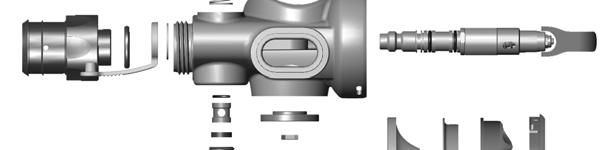
11 SS1 DISASSEMBLY 11
12 Removal of Mouthpiece The serial number is located under the mouthpiece and can be identified by the letter S followed by several numbers. Remove the mouthpiece by cutting the cable tie and gently pull back on the mouthpiece. 12
13 Removal of Front Cover & Diaphragm Position the SS1 on a firm surface with a towel under it to protect it. Using a short, flat bladed screwdriver, insert the blade into one e of the elongated slots in the plastic body. Push down firmly to unlock the tabs of the cover retainer. 13

14 Removal of Front Cover & Diaphragm Repeat to unlock all 4 tabs then withdraw the cover retainer, cover, inner ring and diaphragm. 14


15 Removal of Inflator Stem Unscrew the inflator cover using the Atomic 2 nd Stage tool. Using the short flat bladed screwdriver, unscrew the plastic seal retainer from the plastic body. 15


16 Removal of Inflator Stem Now depress the inflator button and unscrew the inflator stem from the button. Put the button and spring aside. Push the stem and rubber seal out of the plastic body. 16


17 Removal of Inflator Stem Using an o-ring o pick, remove the inflation spool from the body. Using an o-ring o pick, remove the inflator cover o-ring. o The inflator stem o-ringo is located inside the body, beneath the inflation spool. Remove it also. 17

18 Removal of Exhaust Valve Unscrew the plastic exhaust cover. Lift up the edges of the exhaust valve and unscrew the plastic exhaust valve spider. If it is too tight, use the open jaws of a pair of long nosed pliers placed in between the legs of the spider to unscrew it. 18


19 Removal of Exhaust Valve Seal Remove the thin rubber gasket. Using the 5/16 nut driver, unscrew the nut holding the exhaust seal from the exhaust stem. 19
.")
20 Removal of Deflation Button The button, stem, spring, washer and o-ring are now free from the case. Leave the stem attached to the button. (If the washer and o-ring o do not come free during the last procedure, gently remove them with an o-ring o pick). If the unscrewing the nut happens to unscrew the stem from the button instead, the result will be the same. 20


21 Removal of Valve Body from the Case Pull back and remove the hard rubber dust protector from the inlet nipple. Using an o-ring o pick, push the C-C clip out of its groove and slide it off the nipple. Do not spread it open or you will bend it. 21
22 Removal of Valve Body from the Case Push the valve body assembly out of the plastic body. 22
23 Disassembly of Valve Body Using a 1/2 open end wrench on the inlet and adjustable wrench on the valve housing, unscrew the inlet from the housing. Be careful not to slip the wrench and damage the wrench flats on the inlet. Hex wrench Push the orifice out of the inlet tube with a 3/16 hex wrench. 23

24 Disassembly of Valve Housing Leave the orifice sleeve in the housing. This will keep the parts from falling out during the next step. Sleeve Using a 1/4 nut driver, unscrew the locknut completely from the poppet. 24


25 Disassembly of Valve Housing Place the orifice back into the sleeve. Using the orifice, unscrew the orifice sleeve with a 3/16 hex wrench allowing the spring and lever to drop free of the housing. 25
26 Disassembly of Valve Housing Save the washer and small plastic insert in the top of the housing. Replace the locknut with a new one in the service kit. The following components should now be removed. 26


27 Disassembly of Poppet Seat Remove the low pressure seat prior to ultrasonically cleaning the poppet.. The use of a knife blade can aid in the removal. 27

28 SS1 REASSEMBLY 28
29 Reassembly of Deflation Button Replace and generously lubricate the o-ring o in the plastic case. Coat the top of the o-ring o with lubricant and place the washer on top of it. Coat the stem with a thin film of lubricant and place the spring onto the shaft (small end toward washer). Install the button and stem into the body. 29
30 Reassembly of Deflation Button Depress the deflation button down and hold in that position until the exhaust seal has been installed. Install the exhaust seal onto the shaft (metal insert side up). Install the nut onto the exhaust seal. Securely tighten using a 5/16 nut driver. (Do not over tighten) Operate the button several times to insure it works smoothly. 30

31 Reassembly of Exhaust Valve Replace the gasket onto the exhaust valve spider. Hold the spider upright to keep the gasket in place and screw the spider with the exhaust valve into the case. Gasket Snug it hand tight. Make sure the spider is completely screwed in. Operate the deflation button to insure the exhaust seal seats on the spider when the button is fully depressed. 31
32 Reassembly of Exhaust Valve Replace the exhaust cover and snug it hand tight. 32
33 Reassembly of Inflator Stem Replace and generously lubricate the inflator stem o-ring, o and install it into the plastic case. Follow the o-ring o with the inflation spool (white bushing), and the rubber seal. 33

34 Reassembly of Inflator Stem Make sure the inflation spool and rubber seal is seated flush into the case. Insert the stem through the rubber seal coarse thread 1 st and push it through the assembly until the threads come through the top of the case. 34

35 Reassembly of Inflator Stem Place the spring under the inflator button and hold the button in the depressed position. Using the short flat bladed screwdriver, tighten the stem until it is snug. 35

36 Reassembly of Inflator Stem Install the seal retainer and tighten with a flat bladed screwdriver. Replace and install the inflation cap o-ring. o 36

37 Reassembly of Inflator Stem Thread the inflator cap in, and tighten by using the Atomic 2 nd Stage tool. (Do not over tighten) 37
38 Reassembly of Valve Housing Replace the rubber seat in the poppet with a new one. The seat should be completely flat and flush with the end of the poppet. You may wet the poppet to aid assembly. Place the housing insert over the housing making sure to align the flats in each end. 38


39 Reassembly of Valve Housing Place the poppet on top of the nipple, aligning the flats on the poppet facing front and back. The flats should be facing towards you. 39


40 Reassembly of Valve Housing Place the spring and housing on top of the poppet.. Align the flats of the poppet with the flats of the housing. Compress the spring with the housing until the poppet threads push through the insert in the housing. 40


41 Reassembly of Valve Housing The lever is installed so it leans AWAY FROM the oval shaped aperture of the housing. While pushing down on the housing place the lever, washer and new locknut onto the poppet. Verify that the lever is leaning away from aperture hole and thread the locknut on so that 1-21 threads are shown. 41

 with a 3/16 hex wrench.")
42 Reassembly of Valve Housing Screw the orifice and sleeve into the housing (flat side first) with a 3/16 hex wrench. 42
43 Reassembly of Valve Housing Using a 1/2 open end wrench on the inlet and adjustable wrench on the valve housing, screw the inlet onto the housing. Be careful not to slip the wrench and damage the wrench flats on the inlet. 43

44 Reassembly of Valve Body to the Case Push the valve body assembly into the plastic body. Note the flats of the housing align top and bottom. 44
45 Reassembly of Valve body into the case Push the tube completely into the case until the nipple protrudes from the case and the second groove for the c-clip c clip is visible. Install the retaining c-clip c clip by pushing it into its groove. 45

46 Reassembly of Valve body into the case Install the dust cap, and go around it with your fingernail to make sure the cap is installed correctly. 46
47 Adjustment The SS1 is an unbalanced regulator design and its final adjustment will be sensitive to intermediate pressure variations. The adjustment is similar to any unbalanced second stage. Once adjusted, a drop in intermediate pressure will cause the regulator to breathe hard, and a raise in pressure will cause it to breathe easily e and perhaps become overly sensitive. For optimal performance, adjust the SS1 using the first stage it will be used with. If this is not possible, adjust it to the high end of the intermediate pressure range, psi to prevent it from being overly sensitive or leaking in the field. 47
48 Adjustment The initial adjustment of the orifice is fully retracted. Insert a 3/16 hex wrench into the nipple and unscrew it (counterclockwise) until it stops. Remove the wrench and install the quick disconnect. Slowly pressurize the regulator. Check that the lever is loose and has plenty of free play.(1/16 free play) (1/16 ) 48

49 Adjustment If the regulator leaks, remove the quick disconnect, insert the hex wrench and tighten the orifice (turn clockwise) in quarter turn increments and retest until it stops leaking. Readjust the lever locknut so there is about 1/16 free play before it opens the valve. Install the diaphragm and hold in place while testing the cracking effort with a magnehelic gauge. The gauge should read between 1.25 and 1.5 with a light breath. Readjust the orifice and lever until this reading is obtained. Each time the orifice is adjusted the lever height will change and need to be readjusted. 49


50 Reassembly of Front Cover & Diaphragm Hold the diaphragm to the light and check for tears or holes. Replace if needed. Replace the diaphragm into the plastic case. Make sure the lip of the diaphragm is seated into the groove and that it is straight. Place the inner ring into the back of the front cover. Place the front cover with the ring into the top of the diaphragm. Make sure the logo is oriented correctly. 50


51 Reassembly of Front Cover & Diaphragm Align the cover retainer around the cover and press it into place 1-corner at a time until all 4 locking tabs lock into place in the case. (Listen for 4 distinctive snaps ) CORRECT 51
52 Installation of Mouthpiece Stretch the mouthpiece wide enough to allow in slip onto the case e of the regulator. Use a cable tie (Zip tie) to securely hold the mouthpiece in place. Use the stock SS1 mouthpiece.. Other mouthpieces may cause freeflow or other undesirable characteristics. 52
53 Final Check 1. Water test the quick disconnect assembly in both connected and disconnected condition for leaks. 2. Check SS1 for proper operation of pneumatic inflation, oral inflation, and deflation. 3. Check regulator inhalation and exhalation. 4. Fully inflate BCD, check all hose connections for tightness and leaks. 53
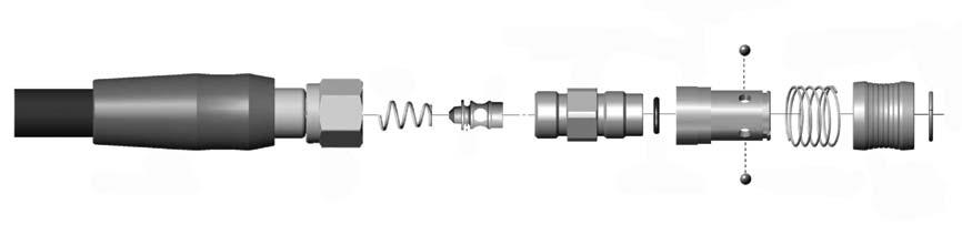
54 QD DISASSEMBLY 54
55 Disassembly of the Quick Disconnect Make sure the hose is not pressurized. Slide back the hose protector. Using two 5/8 wrenches or an adjustable wrench, unscrew the hose body from the QD body. 55
56 Disassembly of the Quick Disconnect For further disassembly, the hose body can be unscrewed from the low-pressure hose using 2 wrenches (11/16 and 5/8 ). This exposes the QD poppet and hose body o-ring. o Hose body o-ringo QD Poppet 56
57 Disassembly of the Quick Disconnect The QD poppet and spring can now be pushed out the back side of the QD body. The o-ring o on the QD poppet and hose body can now be replaced. 57


58 Disassembly of the Quick Disconnect The sleeve and QD body can be further disassembled for cleaning but is not usually needed. There are no serviceable parts inside. To disassemble, pace a towel on the bench top to catch the stainless balls. Using a small o-ring o pick, position it under the c-ring c in the groove that runs across the face of the QD body. Lift the ring out of its groove and off of the end of the QD body. The sleeve will slide off and the balls and spring will drop free of the assembly. 58
59 QD REASSEMBLY 59
60 Reassembly of the Quick Disconnect To keep the balls in place for reassembly, place a small amount of lubricant (Christolube( Christolube) ) into each hole and place each of the 4 balls into the holes. Slide the spring over the balls. 60
61 Reassembly of the Quick Disconnect Follow the spring with the sleeve and slide it over the QD body. The sleeve will fit onto the QD body only one way. Locate the end with the larger opening and slide that end on first. Compress the spring fully within the sleeve and slide the c-ring c into the groove on the QD body to lock it in place. 61

")


62 Reassembly of the Quick Disconnect Replace the o-ring o on the poppet.. Attach the spring (small end) to the end of the poppet and push the poppet into the QD body. Place the o-ring o on the QD body in the groove between the QD body and the poppet. 62


63 Reassembly of the Quick Disconnect The hose body can be attached to the low-pressure hose by using 2 wrenches (11/16 and 5/8 ). 63


64 Reassembly of the Quick Disconnect Using two 5/8 wrenches or an adjustable wrench, tighten the hose body onto the QD body. Slide the hose protector over the QD body. 64
65 17842 Georgetown Lane, Huntington Beach, CA Phone (888) Fax (714) Cover Title. 65
FIRST AND SECOND STAGE REGULATORS TECHNICAL SERVICE PROCEDURES
 FIRST AND SECOND STAGE REGULATORS TECHNICAL SERVICE PROCEDURES Note: These instructions and schematics are intended for use by qualified regulator repair technicians. They are intended to supplement, not
MAINTENANCE PROCEDURE FOR X 650
 MAINTENANCE PROCEDURE FOR X 650 X 650 25. juli 2005-1/6 MAINTENANCE PROCEDURE FOR X 650 2 ND STAGE WARNING: This maintenance procedure is only for appointed Scubapro technicians that completed a course
RG1200 Service and Repair Manual
 Dive Rite RG 1200 Regulator Service and Repair Manual Page 1 Text and Photography by Pete Nawrocky Copyright ( ) 1999-2000, Lamartek, Inc., dba Dive Rite RG1200 Service and Repair Manual First Stage.........................................
SCUBAPRO. Balanced Power Inflator
 SCUBAPRO Balanced Power Inflator USE THIS GUIDE AS A REFERENCE WHEN SERVICING THE BALANCED POWER INFLATOR Important note: The following information is not designed to be a complete training guide for servicing
SERVICE INSTRUCTIONS
 SERVICE INSTRUCTIONS GEMINI BREATHABLE INFLATOR SR9000 INTRODUCTION The instructions set forth in this document are intended to guide the experienced scuba equipment repair technician through the standard
500SE SECOND STAGE SERVICE PROCEDURE
 500SE SECOND STAGE SERVICE PROCEDURE This 500SE Service Procedure conveys a list of components and service procedures that reflect the 500SE as it was configured at the time of this writing. CONTENTS TROUBLESHOOTING...
12S 1st Stage. -Maintenance Procedure-
 12S 1st Stage -Maintenance Procedure- 1 Warning! All maintenance and repair procedures MUST be performed by a Mares authorized Service Center and/or Distributor. Therefore, the information provided below
G250/G250 HP Compatibility of Upgrade Kit
 Engineering Bulletin December 15, 1999 #266 G250/G250 HP Compatibility of Upgrade Kit Page 1 of 9 The SCUBAPRO G250 HP is a marked improvement on the proven G250 second stage design. So much so that issues
Service and Repair Manual
 II stage R2 Ice/ Special, II stage R 1 Pro DOWNSTREAM 2 nd STAGE REGULATOR Service and Repair Manual Introduction Safety Precautions...4 General Procedures, Maintenance Schedules...5 Initial Inspection
SCUBAPRO Repair Guide. S600-S550 Second Stages
 SCUBAPRO Repair Guide S600-S550 Second Stages S600 Configuration A S600 Configuration B USE THIS GUIDE AS A REFERENCE WHEN SERVICING THE S600 AND S550 SECOND STAGES S550 P/N 41-047-000 FOR REPAIR OF S600-S550
Contents. Stainless Steel Side Block. 1.1 Separating the Side Block. Stainless Steel Side Block Reassembly of. Assembly from the Helmet Shell
 Separating the Side Block Assembly from the Helmet Shell Contents SSB-1 SSB-3 SSB-5 SSB-5 SSB-7 1.1 Separating the Side Block Assembly from the Helmet Shell 1.2 Side Block Assembly Replacement 1.3 Defogger
Maintenance and Repair. AirHawk II Air Mask. Second Stage Regulator. Order No.: /02 Prnt. Spec (I) MSAsafety.
 MSAsafety.") Maintenance and Repair Second Stage Regulator Order No.: 10104241/02 Prnt. Spec. 10000005389(I) MSAsafety.com WARNING! Read this manual carefully before servicing the device. The device will perform as
Maintenance and Repair Second Stage Regulator Order No.: 10104241/02 Prnt. Spec. 10000005389(I) MSAsafety.com WARNING! Read this manual carefully before servicing the device. The device will perform as
Balanced SCUBA Second Stage Regulator (P/N ) Maintenance Manual Contents
 Maintenance Manual Contents") Before Going Further Introduction Balanced SCUBA Second Stage Regulator (P/N 200-120) Maintenance Manual Contents SCBAL-1 SCBAL-1 SCBAL-1 SCBAL-2 SCBAL-2 SCBAL-2 SCBAL-2 SCBAL-2 SCBAL-3 SCBAL-3 SCBAL-3
Before Going Further Introduction Balanced SCUBA Second Stage Regulator (P/N 200-120) Maintenance Manual Contents SCBAL-1 SCBAL-1 SCBAL-1 SCBAL-2 SCBAL-2 SCBAL-2 SCBAL-2 SCBAL-2 SCBAL-3 SCBAL-3 SCBAL-3
RG2200 BC Integrated Octopus
 175 NW Washington Street Lake City, Florida 32055, USA Web: www.diverite.com Phone: 386.752.1087 Fax: 386.755.0613 RG2200 BC Integrated Octopus Product description The Rite Source is both a BC inflation/deflation
 INTRODUCTION The instructions set forth in this document are intended to guide the experienced scuba equipment repair technician through the standard service procedure for this Sherwood regulator. It is
Gemini Owner s Manual
 Gemini Owner s Manual WARNING - Improper use of the Gemini Breathable Inflator may result in serious injury or death. Do not attempt to use this product unless you have received certified scuba instruction
Toll Free: (888) M A D E I N T H E U. S. A.
 M A D E I N T H E U. S. A.") O W N E R S M A N U A L Toll Free: (888) 270-8595 www.atomicaquatics.com M A D E I N T H E U. S. A. 28 1/10 29 TA B L E O F C O N T E N T S I N T R O D U C T I O N Introduction... 3 Thank you for choosing
O W N E R S M A N U A L Toll Free: (888) 270-8595 www.atomicaquatics.com M A D E I N T H E U. S. A. 28 1/10 29 TA B L E O F C O N T E N T S I N T R O D U C T I O N Introduction... 3 Thank you for choosing
SECOND STAGE SERVICE GUIDE
 SECOND STAGE SERVICE GUIDE 200_08 SRB1000 INTRODUCTION The instructions set forth in this document are intended to guide the experienced scuba equipment repair technician through the standard service procedure
Regulators repair and maintenance. XS Compact 2nd stage. January 2014 Rev XSC /3 Ed. C /14 1
 XS Compact 2nd stage January 2014 Rev XSC /3 Ed. C /14 1 XS Compact 2nd stage WARNING! This manual is intended for use by expert technicians who have already received training in equipment repairs and
SR2 Service Manual - Second Stage -
 SR2 Service Manual - Second Stage - 1 INTRODUCTION The instructions set forth in this document are intended to guide the experienced scuba equipment repair technician through the standard service procedure
Balanced SCUBA Second Stage Regulator (P/N ) Contents
 Contents") Introduction (P/N 200-120) Contents SCBAL-1 SCBAL-1 SCBAL-1 SCBAL-2 SCBAL-2 SCBAL-2 SCBAL-2 SCBAL-2 SCBAL-3 SCBAL-3 SCBAL-3 SCBAL-3 SCBAL-4 1.1 Before Going Further 1.2 General Information 1.2.1 Introduction
Introduction (P/N 200-120) Contents SCBAL-1 SCBAL-1 SCBAL-1 SCBAL-2 SCBAL-2 SCBAL-2 SCBAL-2 SCBAL-2 SCBAL-3 SCBAL-3 SCBAL-3 SCBAL-3 SCBAL-4 1.1 Before Going Further 1.2 General Information 1.2.1 Introduction
SOTR Special Operations Tactical Respirator
 SOTR Special Operations Tactical Respirator OPERATOR S MANUAL FOR INDIVIDUAL RESPIRATORY PROTECTION OPS-CORE 2018 OMM G055-1000 REV. B INTRODUCTION ABOUT YOUR SOTR The Ops-Core Special Operations Tactical
Product Information News
 Product Information News MMR SECOND STAGE REGULATOR VALVE CORE MSA has changed its recommended rebuilding of the MMR Second Stage Regulator s bypass sleeve assembly during the annual inspection. Based
RG3100 and RG3100Ice Regulator System
 RG3100 and RG3100Ice Regulator System User Guide www.diverite.com Date of purchase: www.diverite.com RG1208-5 & RG1208-5Ice www.diverite.com First Stage Regulator Product Description The RG1208-5 and RG1208-5Ice
THERE WHEN YOU NEED IT
 SPARE AIR SERVICE MANUAL FOR ALL MODELS 18072 Gothard Street, Huntington Beach, CA 92648 USA 800-648-DIVE P: 714-842-6566 F: 714-842-4626 www.spareair.com e-mail: info@submersiblesystems.com THERE WHEN
RG1200 Regulator System
 RG1200 Regulator System UserGuide Date of purchase: www.diverite.com DEVELOPED BY COPYRIGHT NOTICE WARRANTY INFORMATION Dive Rite 175 NW Washington Street Lake City, FL 32055 Phone: 386.752.1087 Fax:
CS150 CAP STAPLER OWNER S MANUAL
 Operation Revised 6/2013 www.stingerworld.com CS150 CAP STAPLER OWNER S MANUAL! Maintenance Safety Warranty PLEASE READ! This manual contains important information about product safety. WELCOME TO STINGER
Product Information News September 26, 2003
 Product Information News September 26, 2003 LEVER HEIGHT INSPECTION FOR FIREHAWK MMR MSA is announcing a revision to the instructions for the Firehawk MMR Second Stage Regulator as they relate to the air
SERVICE AND REPAIR MANUAL ALTAIR OCTO PN RG300. Service & Repair Manual. Revised - 02/11
 SERVICE AND REPAIR MANUAL ALTAIR OCTO PN RG300 Service & Repair Manual Revised - 02/11 AltAir Octo Contents Section 1 - Introduction Scheduled Service... 3 EAN/ Nitrox Service... 3 Facility Requirements...
Compact Triple Cabinet Outlet Station Model Installation and Operating Instructions
 Compact Triple Cabinet Outlet Station Model 6258-1 Installation and Operating Instructions The Porter Compact Triple Outlet Station (6258-1) provides a quick, safe, and reliable method of connection to
User Instruction Manual
 User Instruction Manual 4500 psi Air Compressor Ver 2, 1.18 Contents Parts Included...3 Assembly Instructions...3-5 Operation Instructions...6-7 Oil Change Intervals...8 Air Filter Replacement...9 Setting
600 / 600FC OWNER'S MANUAL
 PROGRESSION 600 / 600FC OWNER'S MANUAL Issue 2 / Version E - Dec. 10, 1997 Copyright 1997 GAMMA Sports - All Rights Reserved PROGRESSION 600 / 600FC OWNER'S MANUAL TABLE OF CONTENTS PAGE 1... WARRANTY
Installation Troubleshooting Maintenance Instructions Installation / Start-up
 Model ZW207 Installation Troubleshooting Maintenance Instructions Installation / Start-up NOTE: Flushing of all pipe lines is to be performed to remove all debris prior to installing valve. 1. For making
OCTO SRB9150 SRB9350 BRUT MAGNUM SECOND STAGES SERVICE GUIDE
 SR9952 OCTO SRB9150 SRB9350 BRUT MAGNUM SECOND STAGES SERVICE GUIDE 1 INTRODUCTION The instructions set forth in this document are intended to guide the experienced scuba equipment repair technician through
Combination Breathing Apparatus
 and Combination Breathing Apparatus ULTRAVUE FACEPIECE TAL 502 (L) Rev. 0 MSA 2005 Prnt. Spec. 10000005389 (I) Mat. 10064385 Doc. 10064385 ULTRAVUE FACEPIECE COMPONENTS Item Part No. Description 800509
CONSHELF XIV TECHNICAL MANUAL
 CONSHELF XIV TECHNICAL MANUAL Rev. 3/17 2 Conshelf XIV Technical Manual COPYRIGHT NOTICE This manual is copyrighted, all rights reserved. It may not, in whole or in part, be copied, photocopied, reproduced,
Assembly Drawing: W-311B-A01, or as applicable Parts List: W-311B-A01-1, or as applicable Special Tools: , , &
 REDQ Regulators Model 411B Barstock Design Powreactor Dome Regulator OPERATION AND MAINTENANCE Contents Scope..............................1 Installation..........................1 General Description....................1
Air Mask Low/High Pressure
 Air Mask Low/High Pressure USERS MAINTENANCE INSTRUCTIONS THIS MANUAL MUST BE CAREFULLY READ AND FOLLOWED BY ALL PERSONS WHO HAVE OR WILL HAVE THE RESPONSIBILITY FOR USING OR SERVICING THIS AIR MASK. This
RB70 Automatic Diluent Valve Maintenance Manual. Version 1.1 November 2006 Written by Tino de Rijk. Page 1 of 23
 RB70 Automatic Diluent Valve Maintenance Manual Version 1.1 November 2006 Written by Tino de Rijk Page 1 of 23 Table of Contents 1. Introduction... 3 2. ADV diagram and parts list (Pre June 2006)... 4
Service and Repair Operative Manual MC9 1 st STAGE. MC9 1 st Stage. 1 st STAGE MC9. Jannuary Rev. MC9 /B Ed. C/13
 MC9 1 st Stage 137 1 st STAGE MC9 Jannuary 2009 - Rev. MC9 /B Ed. C/13 138 WARNING! This manual is intended for use by expert technicians who should attend or have already received training in equipment
Parts List. 7. Handlebars 8. Grips 9. Handlebar Stem 10. Front Brake 11. Front Wheel 12. Crank 13. Chain
 Woodworm Cruise Parts List 1. Free Wheel with Rear Hub 2. Fenders 3. Fender Stay 4. Quick Release 5. Saddle 6. Seat Post 7. Handlebars 8. Grips 9. Handlebar Stem 10. Front Brake 11. Front Wheel 12. Crank
SERVICE AND REPAIR MANUAL SPIRIT REGULATOR PN RG100. Service & Repair Manual. Revised - 02/11
 SERVICE AND REPAIR MANUAL SPIRIT REGULATOR PN RG100 Service & Repair Manual Revised - 02/11 Spirit Regulator Contents Section 1 - Introduction Warnings, Cautions, & Notes... 3 Scheduled Service... 3 EAN/
! WARNING! IMPORTANT HPA AIR TANK SAFETY INSTRUCTION AND GUIDELINES ! WARNING! IMPORTANT SAFETY INSTRUCTION AND GUIDELINES
 ! WARNING! IMPORTANT SAFETY INSTRUCTION AND GUIDELINES! WARNING! IMPORTANT HPA AIR TANK SAFETY INSTRUCTION AND GUIDELINES This Paintball Marker is NOT A TOY. Misuse can cause serious injury or death. It
Contents Post Dive Reassembly. SuperFlow 350 Regulator. Adjustment System 1.3 Regulator & Exhaust System Overhaul
 SuperFlow 350 Regulator & Exhaust System Post Dive Cleaning & Sanitizing SuperFlow 350 Regulator Contents SF350-1 SF350-1 SF350-3 SF350-3 SF350-3 SF350-4 SF350-4 SF350-4 1.1 SuperFlow 350 Regulator & Exhaust
 CS150 CAP STAPLER OWNER S MANUAL Operation Safety Maintenance Warranty! www.stingerworld.com PLEASE READ! This manual contains important information about product safety. REV 06/15 WELCOME TO STINGER Congratula*ons
LIQUIP DRYBREAK COUPLER. API800 Series MAINTENANCE INSTRUCTIONS
 LIQUIP DRYBREAK COUPLER API800 Series MAINTENANCE INSTRUCTIONS API LOADING COUPLER TO API RP1004 June 2015 Issue: F M:\Product-Info\API8xx\6-Service-Maintenance\API800 MAINTENANCE INSTRUCTIONS 40183.doc
SERVICE AND REPAIR MANUAL SEAAIR REGULATOR PN RG200. Service & Repair Manual. Revised - 02/11
 SERVICE AND REPAIR MANUAL SEAAIR REGULATOR PN RG200 Service & Repair Manual Revised - 02/11 SeaAir Regulator Contents Section 1 - Introduction Warnings, Cautions, & Notes...3 Scheduled Service...3 EAN/
Training. Testor Training Manual
 Training Testor Training Manual Index Section 1 Introduction and Safety Warnings Section 2 Test Procedures Section 3 Test Hoses Section 4 Fault Location 1:1 1.1 Introduction The Dräger Testor test equipment
PROPORTIONING VALVE. Model 150 INSTRUCTION MANUAL. March 2017 IMS Company Stafford Road
 PROPORTIONING VALVE Model 150 INSTRUCTION MANUAL March 2017 IMS Company 10373 Stafford Road Telephone: (440) 543-1615 Fax: (440) 543-1069 Email: sales@imscompany.com 1 Introduction IMS Company reserves
MMR Air Mask With. with Quick-Connect Hose
 MMR Air Mask With with Quick-Connect Hose Upgrade Kits P/N 10025120 Slide to Connect P/N 10050038 Slide to Connect w/ Solid Cover P/N 10038666 Push To Connect P/N 10050037 Push To Connect w/ Solid Cover
Contents. REX Regulator and Oral Nasal. 1.1 Regulator Performance Kirby Morgan Tools for the REX REX Regulator
 Regulator Performance Contents REX-1 REX-1 REX-1 REX-2 REX-2 REX-3 REX-3 REX-4 REX-5 REX-6 REX-6 1.1 Regulator Performance 1.1.1 REX Regulator 1.1.2 Kirby Morgan Tools for the REX Regulator 1.2 REX Demand
Anderson Greenwood Series 93 Positive Pressure POSRV Installation and Maintenance Instructions
 Before installation these instructions must be fully read and understood Installation and maintenance instructions for Series 93 Positive Pressure Pilot Operated Safety Relief Valves (POSRV). The intent
REGULATORS OMEGA II SECOND STAGE TROUBLE SHOOTING SYMPTOM POSSIBLE CAUSE TREATMENT
 TOUBLE SHOOTING SYMPTOM POSSIBLE CAUSE TEATMENT * Freeflow 1. Incorrectly positioned during water entry. 2. Second stage adjusted too sensitively. 3. Excessive intermediate pressure from first stage. 4.
COMPACT TRIPLE WALL OUTLET STATION MODEL INSTALLATION AND OPERATING INSTRUCTIONS
 COMPACT TRIPLE WALL OUTLET STATION MODEL 6255-1 INSTALLATION AND OPERATING INSTRUCTIONS To assure safe operation and conformation to local fire codes, all Porter Outlet Stations are designed to be used
OWNER'S MANUAL. Copyright 1999 ATS - All Rights Reserved
 OWNER'S MANUAL AL Issue 2 - August 19, 1999 Copyright 1999 ATS - All Rights Reserved OWNER'S MANUAL TABLE OF CONTENTS PAGE 1... WARRANTY PAGE 2... ASSEMBLY INSTRUCTIONS PAGE 4... MOUNTING THE RACQUET PAGE
INSTALLATION INSTRUCTIONS
 EDGEMERE CENTERSET LAVATORY FAUCET INSTALLATION INSTRUCTIONS 708.0 Thank you for selecting American Standard... the benchmark of fine quality for over 00 years. To ensure that your installation proceeds
Compact Triple Cabinet Outlet Station Model B Installation and Operating Instructions
 PORTER Parker Hannifin Corporation Porter Instrument Division 245 Township Line Rd. P.O. Box 907 Hatfield, PA 19440-0907 USA (215) 723-4000 / fax (215) 723-5106 Compact Triple Cabinet Outlet Station Model
Installation Instructions
 Installation Instructions COLONY SOFT 7.0 Centerset Lavatory Faucet 7.0 with Speed Connect Drain Congratulations on purchasing your American Standard faucet with the Speed Connect drain, a features found
SERVICE MANUAL LEGEND FIRST STAGE
 SERVICE MANUAL LEGEND FIRST STAGE Copyright 2005 Aqualung France Rev. 02/2005 2 Legend First Stage Service Manual Index COPYRIGHT... 3 INTRODUCTION... 3 WARNINGS, ATTENTION, NOTE...... 3 MAINTENANCE...
Santa Fe Cycles Assembly Guide Introduction
 Santa Fe Cycles Assembly Guide Introduction Congratulations on your purchase of your new Santa Fe bicycle. You have purchased a bicycle that has many features and qualities. Please take a few minutes and
AP100 AUTO AIR. User Instruction Manual
 AP100 AUTO AIR User Instruction Manual Contents Important Information... 3 Introduction... 4 How the Auto Air Works... 5 Emergency Breathing... 5 Using the Auto Air as an alternative 2nd stage or "Octopus"....
GORSKI G2000SS DIVING HELMET TECHNICAL MANUAL
 GORSKI G2000SS DIVING HELMET TECHNICAL MANUAL REVISION 06/11 COPYRIGHT NOTICE This manual is copyrighted, all rights reserved. It may not, in whole or in part, be copied, photocopied, reproduced, translated,
Chapter 9 Accessories
 SuperLite 17B Chapter 9 Accessories 9.1 Introduction This section provides the manufacturer s advice on how to install KMDSI accessories including the Hot Water Shroud, Low Pressure Inflator Hoses, and
Pressure Dump Valve Service Kit for Series 2300 Units
 Instruction Sheet Pressure Dump Valve Service Kit for Series 00 Units. Overview The Nordson pressure dump valve is used to relieve hydraulic pressure instantly in Series 00 applicator tanks when the unit
accidents which arise due to non-observance of these instructions and the safety information herein. SPECIFICATIONS
 18 GAUGE 1-1/4 INCH BRAD NAILER Model: 7611 CALIFORNIA PROPOSITION 65 WARNING: You can create dust when you cut, sand, drill or grind materials such as wood, paint, metal, concrete, cement, or other masonry.
MODEL 200 KNIFE GATE VALVES INSTALLATION & MAINTENANCE MANUAL
 MODEL 200 KNIFE GATE VALVES INSTALLATION & MAINTENANCE MANUAL Index 1. List of components / General arrangement 2. Description 3. Handling 4. Installation 5. Actuators / Operation 6. Maintenance a. Changing
Training. tm PA90 Series - Lung Demand Valve
 D Training Dräger tm12842 PA90 Series - Lung Demand Valve Index Section 1 Instructions for Use Section 2 Introduction and Safety Warnings Section 3 Product Description Section 4 Operating Principle Section
Welker Sampler. Model GSS-1. Installation, Operation, and Maintenance Manual
 Installation, Operation, and Maintenance Manual Welker Sampler Model GSS-1 The information in this manual has been carefully checked for accuracy and is intended to be used as a guide to operations. Correct
DRAFT 12/17/03 KMB 18/28 (BANDMASK) OVERHAUL, MAINTENANCE, AND INSPECTION CHECKLIST APPENDIX A
 OVERHAUL, MAINTENANCE, AND INSPECTION CHECKLIST APPENDIX A") KMB 18/28 (BANDMASK) OVERHAUL, MAINTENANCE, AND INSPECTION CHECKLIST APPENDIX A2.1 12-17-03 THIS INSPECTION AND MAINTENANCE MUST BE PERFORMED AT LEAST ANNUALLY AND AS DICTATED BY CONDITION REVEALED DURING
KMB 18/28 (BANDMASK) OVERHAUL, MAINTENANCE, AND INSPECTION CHECKLIST APPENDIX A2.1 12-17-03 THIS INSPECTION AND MAINTENANCE MUST BE PERFORMED AT LEAST ANNUALLY AND AS DICTATED BY CONDITION REVEALED DURING
Hydraulic Piston Accumulators
 Ride Control Engineering Services PWCE Extendavator Paul Wever Construction Equipment Co., Inc. P.O. Box 85 401 Martin Drive Goodfield, IL 61742-0085 Phone (309) 965-2005 Fax (309) 965-2905 1-800-990-PWCE
MUELLER. Mega-Lite Drilling Machine. Reliable Connections. table of contents PAGE. Equipment 2. Operating Instructions 3-4. Parts Information 5
 operating Instructions manual MUELLER Mega-Lite Drilling Machine table of contents PAGE Equipment 2 Operating Instructions 3-4 Parts Information 5 Travel Charts 6-11! WARNING: 1. Read and follow instructions
JARVIS. Model CPE Hock and Neck Cutter EQUIPMENT... TABLE OF
 74 Hock and Neck Cutter EQUIPMENT SELECTION... Ordering No. TABLE OF CONTENTS... Page with Control Circuit. 4304003 only... 4304004 Balancer... 1350084 Control Circuit... 3350010 Air Hose (Yellow)... 3323003
isup MANUAL THANK YOU FOR PURCHASING A KAHUNA isup, WE HOPE YOU HAVE MANY YEARS OF PADDLING ENJOYMENT.
 i isup MANUAL THANK YOU FOR PURCHASING A KAHUNA isup, WE HOPE YOU HAVE MANY YEARS OF PADDLING ENJOYMENT. THIS MANUAL IS A GENERAL GUIDELINE FOR SET-UP, CARE AND PROPER USE. PLEASE REFER TO OUR WEBSITE
( SC) NOTE: KMDSI strongly recommends that all repairs be performed by trained Personnel.
 NOTE: KMDSI strongly recommends that all repairs be performed by trained Personnel.") KIRBY MORGAN SUPERLITE DEEP SEA DIVING HELMET MODELS 17 A/B, 17C, 17K, & KM 37, KM 47, KM 57, KM 77 & KM 97 MONTHLY INSPECTION AND MAINTENANCE CHECKLIST Appendix A2.2 (10-2-2016 SC) This inspection is
KIRBY MORGAN SUPERLITE DEEP SEA DIVING HELMET MODELS 17 A/B, 17C, 17K, & KM 37, KM 47, KM 57, KM 77 & KM 97 MONTHLY INSPECTION AND MAINTENANCE CHECKLIST Appendix A2.2 (10-2-2016 SC) This inspection is
CHAPTER 5 REWIND STARTERS
 GENERAL INFORMATION CHAPTER 5 REWIND S Rewind starters used on vertical shaft Tecumseh engines are top mount horizontal pull style or side mount vertical pull style. Horizontal shaft engines use side mounted
Thermo Valves Corporation
 Scuba Diving Valves Maintenance Manual The Leader in High Pressure Technology Date: 07/31/05 Thermo Scuba Products are Sold Through Authorized Distributors Only Thermo PRO Thermo Modular This document
The Envoy. Regulator Service Manual. For Zeagle Envoy 1st and 2nd Stage Scuba Regulators
 The Envoy Regulator Service Manual For Zeagle Envoy 1st and 2nd Stage Scuba Regulators Envoy 1st Stage Parts ITEM # PART # DESCRIPTION... 3 341-0152-AA Label 5 341-0103-CD Spring Adjuster 6 341-0102-CD
OWNER'S MANUAL. Copyright 2003 GAMMA - All Rights Reserved
 OWNER'S MANUAL AL Issue 1 - December 2003 Copyright 2003 GAMMA - All Rights Reserved OWNER'S MANUAL TABLE OF CONTENTS PAGE 1... WARRANTY PAGE 2... ASSEMBLY INSTRUCTIONS PAGE 4... MOUNTING THE RACQUET PAGE
Service & Repair Manual
 Powerline Inflator (With Dual Valve) Service & Repair Manual for Authorized Sea Quest Service Centers Doc. No. 42983 1999 Sea Quest, Inc. 2 Sea Quest Powerline Service and Repair Manual Contents Introduction...
Freedom8 ShoeBox Compressor Manual
 Freedom8 ShoeBox Compressor Manual Warning!! This product is not a toy! Use or misuse can cause severe injury or death! Use only with adult supervision. This unit is only to be used with tanks, hoses and
Yoke Block Instruction Manual
 Yoke Block Instruction Manual ! WARNING IMPORTANT: READ MANUAL COMPLETELY BEFORE OPERATING THIS DEVICE This manual contains instructions on periodically required checks to be performed by the user. These
G7S Hand Pump Owner s Manual
 G7S Hand Pump Owner s Manual Copyright Air Venturi 2018 Version 4-18 Specifications 24.80 inches long closed 43.31 inches long extended 4500 psi/310 bar max pressure Features Integral manometer (pressure
T1-Titanium HVLP Pressure Feed Spray Gun
 T1-Titanium HVLP Pressure Feed Spray Gun THE SPRAY GUN PEOPLE FOR PRODUCT INFORMATION CALL: 1-800-742-7731 Important Safety Instructions Read all warnings and instructions in this manual. Save these instructions.
SERVICE & REPAIR MANUAL H.A.B.D.
 Authorized Technician SERVICE & REPAIR MANUAL H.A.B.D. (Helicopter Aircrew Breathing Device) Rev. 02/16 2 H.A.B.D. Service & Repair Manual COPYRIGHT NOTICE This owner s manual is copyrighted, all rights
Contents. SuperFlow Regulator. 1.1 SuperFlow Demand Regulator. SuperFlow Regulator SuperFlow Demand. Regulator
 SuperFlow Demand Regulator SuperFlow Regulator Contents SF-1 SF-1 SF-2 SF-2 SF-4 SF-5 SF-5 SF-6 SF-8 1.1 SuperFlow Demand Regulator 1.1.1 General Regulator Information 1.1.2 SuperFlow Demand Regulator
Aluminum 13 cu tank Includes regulator Fill pressure: 3,000 psi (200 bar) Output: 1,100 psi +/- 10% (75bar)
 Output: 1,100 psi +/- 10% (75bar)") Aluminum 13 cu tank Includes regulator Patent numbers: 6,851,447 7,059,343 7,051,751 Fill pressure: 3,000 psi (200 bar) Output: 1,100 psi +/- 10% (75bar) Contents Safety system... 3 Fill your tank... 4
Aluminum 13 cu tank Includes regulator Patent numbers: 6,851,447 7,059,343 7,051,751 Fill pressure: 3,000 psi (200 bar) Output: 1,100 psi +/- 10% (75bar) Contents Safety system... 3 Fill your tank... 4
TECHNICAL MAINTENANCE MANUAL POWERLINE INFLATOR
 TECHNICAL MAINTENANCE MANUAL POWERLINE INFLATOR 2 CHANGE RECORD PAGE # REV. DATE TITLE OR DESCRIPTION CHANGE MADE BY 9/15/18 11/20/14 Change oral rod torque Spec to 6.5 in-lbs (0.75 Nm) Aqua Lung USA Powerline
1700ESL Kamvalok Coupler
 PART #H32138PA November 2008 1700ESL Kamvalok Coupler OPW Transport Series Dry Disconnect Couplings are considered the standard of the industry. For use on multi-compartment petroleum, solvent and chemical
8. Carefully layout all the parts of the reservoir setup and clean any dirt, grime or dust from the parts. ( image 8 ) 8
 8") INSTRUCTIONS TO SERVICE AMADAXTREME SHOCKS 2.0 REMOTE RES AUSTRALIAN VERSION PART 1 - SERVICE THE RESERVOIR 1.Prior to cleaning the shock check for any leaks or signs of damage to the res, lines, bushes
INSTRUCTIONS TO SERVICE AMADAXTREME SHOCKS 2.0 REMOTE RES AUSTRALIAN VERSION PART 1 - SERVICE THE RESERVOIR 1.Prior to cleaning the shock check for any leaks or signs of damage to the res, lines, bushes
accidents which arise due to non-observance of these instructions and the safety information herein. SPECIFICATIONS
 18 GAUGE 2 INCH BRAD NAILER Model: 7555 CALIFORNIA PROPOSITION 65 WARNING: You can create dust when you cut, sand, drill or grind materials such as wood, paint, metal, concrete, cement, or other masonry.
Yoke Block Instruction Manual
 Yoke Block Instruction Manual ! WARNING IMPORTANT: READ MANUAL COMPLETELY BEFORE OPERATING THIS DEVICE This manual contains instructions on periodically required checks to be performed by the user. These
Pressure Dump Valve Service Kit for Series 3000 Units
 Instruction Sheet Pressure Dump Valve Service Kit for Series 000 Units. Overview The Nordson pressure dump valve is used to relieve hydraulic pressure instantly in Series 00, 400, 500, and 700 applicator
CATALYZER TM 2K 10:1 RATIO Pump
 PRODUCT INFORMATION CATALYZER TM 2K 10:1 RATIO Pump The C.A.Technologies CATALYZER is an Air Assist Airless 2 component formulator. Catalyst and base material are pumped into a mixing chamber at 10 : 1
LIQUIP DRYBREAK COUPLER. LYNX Series MAINTENANCE INSTRUCTIONS
 LIQUIP DRYBREAK COUPLER LYNX Series MAINTENANCE INSTRUCTIONS API LOADING COUPLER TO API RP1004 February 2016 Issue: DRAFT A Issue: DRAFT - A 02/01/16 Page 1 CONTENTS LYNX Series Datasheet... 3 LYNX Series
Deep Six Signature Regulator Technician Service Manual
 Deep Six Signature Regulator Technician Service Manual Copyright 2017 Deep Six Expedition Dive Gear Author UDM Consulting All rights reserved. DEDICATION This manual is dedicated to those who choose to
T-016 ASSEMBLY MANUAL MODEL ROCK AND ROLL Main Street NE Minneapolis, MN
 MODEL T-016 ASSEMBLY MANUAL ROCK AND ROLL 5280 Main Street NE Minneapolis, MN 55421 1.877.226.7824 www.kurtkinetic.com COMPONENTS Tools Required for Assembly: 17mm Wrench or Adjustable Wrench When unpacking,
HYDRAULIC PUNCH DRIVER 38456, 38520, 7306 / 7306SB, 7310 / 7310SB, 7506, 7606SB, 7610SB, 7625 / 7625Pg / 7625PgSB, 7646 / 7646Pg / 7646PgSB
 INSTRUCTION MANUAL HYDRAULIC PUNCH DRIVER 38456, 38520, 7306 / 7306SB, 7310 / 7310SB, 7506, 7606SB, 7610SB, 7625 / 7625Pg / 7625PgSB, 7646 / 7646Pg / 7646PgSB Read and understand all of the instructions
Paintball Marker. User s Manual. 530 South Springbrook Road Newberg, OR 97132
 Paintball Marker User s Manual 530 South Springbrook Road Newberg, OR 97132 Component Concepts, Inc., 530 South Springbrook Road, Newberg, OR 97132 Phone: (503) 554-8095 Fax: (503) 554-9370 www.phantomonline.com
MEGR-1627 Instruction Manual
 MEGR-1627 HIGH FLOW GAS REGULATOR Instruction Manual- Look Inside For: Description Installation Remote Vent Line Installations Startup and Adjustment Shutdown Maintenance Body Maintenance Procedures Diaphragm
Anti-flood device Model B-1
 December 4, 2009 Dry Systems 123a 1. DESCRIPTION The Anti-flood Device is required when Viking accelerators are installed on dry systems according to Viking Model E-1 Accelerator Trim Charts. In the SET