REASONS FOR THE DEVELOPMENT
|
|
|
- Scott Harris
- 6 years ago
- Views:
Transcription


1
2
3 7 Series
4
5 7 Series +24VDC VDC OUTPUT MICROPROCESS. E P IN EXH OUT
6
7 7 Series
8 7 ø,8
9 8 7 Series
10 9

11 Series

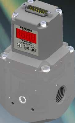
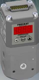
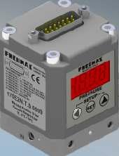
12 Display features The proportional regulator has a 3 /2 digit display and a three-pushbutton touchpad by means of which information on regulator status can be displayed and the functional and operating parameters can be set. Using the display in standard mode When the regulator is switched on, the display shows the outlet pressure value detected by the internal transducer. This value can be displayed in 3 different measuring units (Bar - PSI - MPa) that can be selected by the user. If the right-hand key ( Display letter Meaning Analog input RS-232 Keyboard Digital input () Binary input Levels set by binary codification Value Volt/mA Bar hundredths(e.g. 22) Bar (e.g..22) to 7 to 255 to 7 () N.B. This option is available only for regulators with voltage analog input (letter T in seventh digit of order code). Setting desired pressure value from display If the regulator is configured to use the keyboard of the display as the reference source, press the central key (SET) for 2 seconds to set the desired pressure directly. In particular, the display shows the currently set pressure value, with the last digit on the right flashing (modifiable digit). Press the right-hand key (
13 7 Series Using the display in modify parameters mode To enter modify parameters mode, press the left-hand ( If the password is not enabled, the user accesses the first parameter directly. If the password is enabled the message PSv appears on the display followed by the request to enter the value of the password To enter the value of the password, proceed in this manner: press the right-hand key ( ) to move to the next digit. Once the desired value has been set, press the key (SET). If this is correct, you will enter the parameter configuration menu directly. If the password has not been entered correctly the message EEE will appear on the display and it will not be possible to access the parameter configuration menu. The device will thus return to standard mode. Defining parameters The proportional regulator can be fully customised to meet the needs of the end user. In particular, the device associates with its operating configuration variable details that can be accessed directly via the display or RS-232 serial port. These are from now on defined as PARAMETERS. By varying the parameters it is possible to intervene on the following regulator features: insensitivity unit of measurement of the pressure displayed on the display pressure values corresponding to the minimum and maximum value of the analog signal defining the range of the outlet analog signal defining the intervention thresholds of the digital output Choosing the reference source setting the pressures corresponding to the digital inputs activating the protection for the solenoid valves enabling password and corresponding value speed of convergence on the desired pressure. 2
14 Modifying parameters Once the user has entered the parameters configuration menu (with the previously described procedure), the display is as follows: P identifies the parameter selection mode whilst the number displayed on the right indicates the parameter number. Press the right-hand key () to change the parameter number from (P) to (P22). Each time the key is pressed the number increases by ; if the key is kept pressed the parameter number increases automatically. Once you have identified the parameter that you wish to display or modify, press the key (SET) to access it. After the key (SET) has been pressed the display shows the current value of the selected parameter and enables it to be modified. Depending on the type of parameter, or more characters may be displayed. The procedure for modifying the values is the same as for entering the password: it is possible to modify just one character at a time (the flashing character) by pressing the right-hand key (). On the other hand, if the left-hand key () is pressed, the active character is changed (for those parameters that have more than one character). Once the value to be assigned to the parameter has been set, press the key (SET) to confirm the selection made. If the entered value is acceptable (it belongs to the preset use range and is not in conflict with the value of other parameters) the display confirms that the value has been entered by flashing twice (it switches off and switches on again twice to indicate the set value). A parameter that has been modified in this way is said to have been CONFIRMED. When flashing stops the regulator returns to the parameter selection (it again displays the message P X, X being the last parameter to have been modified). If the entered value is not acceptable (outside the limits set by the manufacturer or in conflict with other parameters) the display shows an error message. If the entered value is less than the lower limit the message ELo appears and the device proposes the minimum permitted value. If the entered value is greater than the upper limit the message EHi appears and the device proposes the maximum permitted value. N.B.: the proposed values are not automatically confirmed. To confirm, press the key (SET). By proceeding in this way (parameter selection, subsequent modification and confirmation) it is possible to modify the value of all the parameters. Once all the values have been modified, in order to enable all the modified values to be saved and to return to the standard operating mode, press the right-hand () and left-hand () keys simultaneously for about two seconds. The regulator confirms the change of operating mode by showing this symbol on the display for about half a second Warning Whilst the regulator is in modify parameters mode outlet pressure is not adjusted, so it cannot be guaranteed that desired pressure corresponds to the outlet pressure. Whilst the regulator is in modify parameters mode RS-232 communication is disabled. Press the two keys ()() to leave modify parameters mode: all the CONFIRMED parameters are saved to the permanent memory and are thus maintained even after switch-off. Analogue and digital output are not updated therefore it is not possible to ensure they are correct; In order to leave modify parameters mode without saving any modified parameter (not even confirmed parameters) wait for two minutes to elapse without pressing any key. Alternatively, switch off the regulator and switch it on again. If the regulator is switched off whilst it is in modify parameters mode no modified parameter is saved to the permanent memory even if it has already been confirmed. 3
15 7 Series List of parameters PARAMETER Desired pressure from keyboard Defines the desired regulator outlet pressure value Bar From minimum pressure (P3) to maximum pressure (P4) Warning: This parameter becomes active only if the parameter (P) is set at 2. Minimum pressure (P3) and maximum pressure (P4) are the operating range. If these values are subsequently modified and the desired pressure value is outside this new range, the device will set the desired pressure (P) automatically at the nearest permitted value PARAMETER Insensitivity Defines the minimum deviation between desired pressure and outlet pressure beyond which the regulator intervenes..3 Bar From.2 to.2 with Parameter 22 at From. to.2 with Parameter 22 at 3 If the difference between outlet pressure and desired pressure exceeds or falls below the (P) parameter value the regulator intervenes to increase or decrease the outlet pressure until the set value is reached. Warning: the smaller the set insensitivity value, the smaller the tolerated deviation will be. In this way, the regulator intervenes much more frequently to control the solenoid valves, generating small variations in outlet pressure. PARAMETER 2 Display unit of measurement Defines the unit of measurement that will be used on the display to show outlet pressure and desired pressure during operation in standard mode. / From to 2 Value 2 Meaning Bar PSI MPa Displayed value.. Warning: All the other parameters linked to pressure (P), (P), (P3), (P4), (P8), (P9), from (P) to (P7) are measured in bar. PARAMETER 3 Minimum pressure Defines the (minimum) outlet pressure value corresponding to the minimum value of the reference signal. The range varies according to the model of transducer used. Minimum pressure must be at least bar less than maximum pressure Product code 7#E2N.#D.9.# 7#E2N.#D.5.# 7#E2N.#D..#... Bar Bar Bar From. to 8.9 From. to PARAMETER 4 Maximum pressure Defines the (maximum) outlet pressure value corresponding to the maximum value of the reference signal. The default value and the range vary according to the model of transducer used. Maximum pressure must be at least bar greater than minimum pressure Product code 7#E2N.#D.9.# 7#E2N.#D.5.# 7#E2N.#D..# Bar Bar Bar From. to 9. From. to 5. From. to. 4
16 PARAMETER 5 Selecting analog input value Defines the range of the analogue input signal managed by the proportional regulator (pin 8 of the 5-pole connector / From to 3 The meaning of the parameter changes according to the model's type of analogue reference. The model can easily be identified by the letter T or C of the order code, and indicates that the analogue reference is a voltage (T) or current (C) controlled signal. PARAMETER 6 Voltage analog output Defines the range of the voltage analogue output (pin 2 of the 5-pole connector). The two limits of the range are the value of the voltage-controlled analogue output corresponding to minimum and maximum outlet pressure. The output will assume all intermediate values in proportion to the outlet pressure. Valore 2 3 T Voltage - V -5 V -5 V User set / C Current 4-2 ma -2 ma -2 ma User set From to 3 Value 2 3 Meaning - V (9 V at 9 bar) -5 V (4.5 V at 9 bar) - V ( V at 9 bar) -5 V (5 V at 9 bar) PARAMETER 7 Current analog output Defines the range of the current analogue output (pin of the 5-pole connector). The two limits of the range are the value of the current-controlled analogue output corresponding to minimum and maximum outlet pressure. The output will assume all intermediate values in proportion to the outlet pressure. / From to Value Meaning 4-2 ma -2 ma PARAMETER 8 Lower threshold for digital output The digital output provides an indication that the outlet pressure corresponds to the desired pressure. It is activated when outlet pressure falls within a range defined by a lower threshold and an upper threshold, both of which can be modified by the user. The digital output is active if the outlet pressure is greater than the desired pressure less the lower threshold and is less than the desired pressure plus the upper threshold. Example: Desired pressure: 3 bar, lower threshold:.5 bar, upper threshold:.8 bar The digital output is active if the outlet pressure is between 2.5 bar (3 -.5) and 3.8 bar. (3 +.8) (pin of the 5-pole connector).5 Bar PARAMETER 9 Upper threshold for digital output See description of parameter (P8) (pin of the 5-pole connector) From. to..5 Bar From. to. 5
17 7 Series PARAMETER Reference source Defines the reference source that the regulator has to use to set outlet pressure. Option 4 is available only for voltagecontrolled regulators (letter T in seventh digit of order code). / From to 5 Value Meaning A nalogue input RS-232 Keyboard Digital-level inputs Binary-code inputs Digital-level inputs with Binary code The regulator sets outlet pressure using the analogue signal (voltage or current) coming from the 5-pole supply connectorat pin 8. The regulator sets outlet pressure using the command coming from the serial port RS The regulator sets outlet pressure directly from the keyboard. The parameter (P) is used to set pressure. 3 The regulator sets outlet pressure via the digital inputs (pin from to 7 of the 5-pole connector). Each of the 7 inputsis matched by a parameter (e.g. Input Parameter P - Input 2 Parameter P2 etc.). By default, all the parameters from P to P7 are set at, if input 3 is activated (+24 VDC) and parameter P3 is, outlet pressure will be setat. If 2 or more inputs are simultaneously active, the outlet pressure will correspond to that of the input with a lower number. E.g. If input 2 and input 5 are active, outlet pressure will be that set by parameter P2 4 The regulator sets outlet pressure via the binary code from to 255 consisting of the logic status of the digital inputs (pin from to 8 of the 5-pole connector) Pin 8 of the connector thus has a dual function: it can be used as an analogue input (e.g. -V) or as a digital input (most significant digit of the binary code). Warning: this option is available for regulators with voltage analogue inputs (letter T in seventh digit of order code). - Verify and ensure that to pin n.8 has been connected only the analogue signal or the digital signal 5 Value 5 has been added as an alternative to value 3. When value 3 is selected up to 7 command signals are needed, which correspond to the 7 parameters (P - P7). When value 5 is selected only 3 electric signals are needed, because there is correspondence between Parameters P - P7 and the binary coding consisting of the logic state of the signals. The regulator sets outlet pressure via the binary coding from to 7 consisting of the logic state of the first digital inputs (pin from to 3 of the 5 pole connector). Combination corresponds to bar pressure. Pin n. Pin n. 2 Pin n. 3 Desidered pressure bar Parameter P Parameter P2 Parameter P3 Parameter P4 Parameter P5 Parameter P6 Parameter P7 Method for calculating status of inputs This formula is used to calculate the binary number to be coded with the logic status of the inputs: Desired pressure - Minimum pressure Maximum pressure - Minimum pressure E.g.: maximum pressure= 5.25 bar; minimum pressure= 3.46 bar; desired pressure= 4.2 bar Decimal number = 255 x ( ) / ( ) = 94 The decimal number then has to be converted into a binary number: 94(decimal) = (binary) The status of the 8 inputs must thus be as follows: Input number Logic status Decimal equivalent 255 x
18 PARAMETER to 7 Define the regulator outlet pressure desired when the corresponding input is active (pin from to 7 of the 5-pole connector). Bar From minimum pressure (P3) to maximum pressure (P4) CONNECTOR PIN = INPUT 2 = INPUT 2 3 = INPUT 3 4 = INPUT 4 5 = INPUT 5 6 = INPUT 6 7 = INPUT 7 Input Parameter Warning: These parameters become active only if the parameter (P) is set at 3 (reference source via digital-level inputs). Minimum pressure (P3) and maximum pressure (P4) are the operating range. If this range is subsequently modified and some pressure values assigned to a level are outside this new range the device will automatically set the pressure at the nearest permitted value. PARAMETER 8 Protection mode If during operation in standard mode the desired pressure cannot be reached (for example, there is no compressed-air supply or it is insufficient) or the discharge conduit is blocked or closed, the regulator continues to work on the solenoid valves to try to reach the desired pressure. This parameter allows the automatic switch-off of the control solenoid valves for up to 2 seconds to be enabled. This function is used to safeguard the solenoid valves over time. The protection is triggered if the desired pressure is not reached and the outlet pressure does not undergo significant variations within a 4-second control of the solenoid valves. A significant variation is defined as a variation that is greater than the defined insensitivity value, parameter P. After the 4 seconds have elapsed in which the regulator attempts to reach the desired pressure, the protection is triggered. This protection switches off the solenoid valves for a maximum of 2 seconds. If the 2 seconds have elapsed or if during the 2 seconds during which the solenoid valves are switched off the required pressure (reference) varies or the outlet pressure varies the regulator will again start to control the solenoid valves for another 4 seconds, trying to reach the desired pressure. If this does not occur, the protection is reactivated. From this point on 4 seconds of controlling the solenoid valves and 2 seconds of switch-off alternate cyclically. When the protection is activated, the message P8 appears on the display alternating with the messages EHi or ELo indicating that the regulator is not reaching the desired pressure due to filling (ELo lack of air) or pressure discharge difficulties (EHi discharge conduit blocked). / From to Value Meaning Deactivated Activated 7
19 7 Series PARAMETER 9 Enabling password request Set this parameter at to enable the password request: this will be requested whenever an attempt is made to access modify parameters mode. / From to Value Meaning Password deactivated Password activated By setting this parameter to the protective password will be switched on, the password will be requested every time that the user will try to access the SET UP menue. Attention: before enabling the password verify and, if necessary, modify parameter P2 PARAMETER 2 Password value This parameter is the password. If the password request (parameter P9) is enabled, this value must be entered whenever an attempt is made to access modify parameters mode. N.B.: the fourth character can have only the values and. is displayed when the point at the bottom on the left is switched on: PARAMETER 2 / Restores all user configuration parameters to default values. From to 999 In order to activate the command that restores parameters to values set by manufacturer, enter the value 333 on the display and confirm the entry. Warning: all changes made previously will be lost (except for parameters P9 and P2) PARAMETER 22 Intervention mode Defines the mode for converging on the desired pressure that the regulator should use / From to 4 Value Meaning Standard mode Efficient mode Accurate mode Sensitive mode Fast mode* Every intervention mode characterises in a particular way the proportional regulator behaviour. In particular: - Standard mode is trade-off between speed and accuracy. - Efficient mode controls solenoid valves to allow a bigger change of outlet pressure. This grants A lower time to fill / empty a volume. It is a specially suitable if there is a big volume to manage or if The inlet airflow is low. As a result of the high fill/empty speed the desired pressure can occasionally be exceeded for a short time. - Accurate mode controls solenoid valves to manage outlet pressure more softly. It is particularly Suitable if there is a little volume to manage or if the inlet airflow is high. This mode is slower than others. 8
20 - Sensitive mode tracks the desired pressure with more frequent changes. It is particularly suitable if a constant outlet pressure is required when the downstream pressure varies due to the application (e.g. working with an inconsistent flow rerquirement). N.B. Each mode may be better suited to an application than the others. The parameters to consider are: Inlet airflow, the volume to be managed, speed and accuracy. We suggest testing each mode on an application to establish which is the most suitable. PARAMETER 23 Reference value of minimum pressure Defines the analogue signal corresponding to minimum pressure. Attention: Used only when Parameter 5 is set at 3 Unit of measurement ma V From to 9 for voltage control From to 9.9 for current control PARAMETER 24 Reference value of maximum pressure Defines the value of the analogue signal corresponding to maximum pressure. Attention: Used only when Parameters 5 is set at Unit of measurement ma V From to for voltage control From. to 2 for current control PARAMETER 25 Linear progression time Inserts a linear progression during the transition between two outlet pressures when the digital inputs state changes. This value represents the time occurred to make this change. Attention: Used only with Parameter set at 3 or at 5 Attention: To activate this time it s needed to activate digital input 8. Unit of measurement ms From to (From. to seconds) AUTOMATIC RESOLUTION OF POSSIBLE CONFLICTS BETWEEN SET PARAMETERS The regulator does not permit desired pressures - parameters (P), (P), (P2), (P3), (P4), (P5), (P6), (P7) and the desired serial pressure to be set outside the operating range (pressure range) defined by the parameters (P3) and (P4). Warning: make sure that the parameters (P3) and (P4) have been entered correctly as the regulator will automatically modify any desired pressure that is outside the operating range. The value assigned will correspond to the nearest permitted value 9
21 7 Series General description All models of the proportional regulator feature the RS-232 serial port that enables a direct connection between the regulator and a computer or a PLC (provided with a serial port) to be established. The regulator has a set of commands that enable all the previously described parameters to be read and modified (except for parameters P, P9, P2 and P2). In addition to this, serial communication can be used to send a reset command to the regulator, read and set the desired pressure and read the outlet pressure Warning: to use the serial port as a reference, set parameter P at 2 Operation Reset Reading a parameter Writing a parameter Writing the desired pressure (hundredths of a bar) Setting the desired pressure (hundredths of bar) Reading desired pressure (hundredths of a bar) Reading outlet pressure value (hundredths of a bar) Desired pressure and reference source reading
22 Commands list After declaring all the operating codes, in order to create a command it is sufficient to structure the sent packet according to the rules defined previously (just include the length of the packet, choose the action to perform on a particular parameter and choose the parameter). There follows the complete list of the messages managed by the regulator with the corresponding replies. Note that, as mentioned previously, the operating code of the reply is the same as that of the command with the addition of 8(h) Key: PP = parameter number - from (h) to 6(h) NN NN = parameter contents When the regulator receives a correct writing command the contents of the NN NN parameter is saved automatically to the permanent memory (EEPROM). Warning: the manufacturer of the microcontroller declares that in extremely critical operating conditions the number of writings guaranteed in EEPROM for the technical features of your product is equal to.. When constant changes in pressure are required, it is possible to use command 22(h), which sets the desired pressure but does not write it in the EEPROM. The parameters are the same as those defined in the previous pages, see the section List of Parameters for explanations of their contents, default values, ranges etc.. N.B.: the Reset command (operating code ) is the equivalent of the regulator hardware switching off. Warning: the reading and writing value of the pressure is always expressed in hundredths of a bar (in hexadecimal notation). Example : Writing desired pressure Regulator outlet pressure of 4.25 bar is desired. The command to be sent to the regulator must be: 4,25 bar = 425 hundredths of a bar = A9(h) Command = 4(h) 2(h) (h) A9(h) Reply = 4(h) A(h) (2(h) + 8(h) ) (h) A9(h) Example 2: Writing desired pressure Let it be assumed, for example, that outlet pressure from the regulator is 6.35 bar. The command for reading its value must be: Command = 2(h) 3F(h) Reply = 4(h) BF(h) (3F(h) +8(h) ) 2(h) 7B(h) 27B(h) = 635 hundredths of a bar = 6,35 bar Warning: Minimum pressure (P3) and maximum pressure (P4) are the operating range. If these values are subsequently modified and the desired pressure value is outside this new range, the device will set the desired pressure automatically at the nearest permitted value. 2
23 7 Series Error messages If the regulator receives a command that it recognises and which does not contain errors it responds with a message in which the operating code is increased by 8(h). If, on the other hand, the regulator receives a command that it does not recognise or which contains errors, it responds with a message in this form: Key: 3 94 EC 3 = Length of message 94 = Operating code of error message. EC = Error message code Error code (EC) Description Regulator in modify parameters mode: command ignored Operating code unknown Value outside range Limit value in conflict with reference Maximum pressure and minimum pressure in conflict Parameter inexistent N.B.: controls for entering parameters from keyboard are also implemented for serial communication; if, for example, an attempt is made to write a minimum pressure value that is greater than the maximum pressure value, a message will be received in response containing the relative error code (5). 22

 T= Voltage signal (- V / -5 V /")


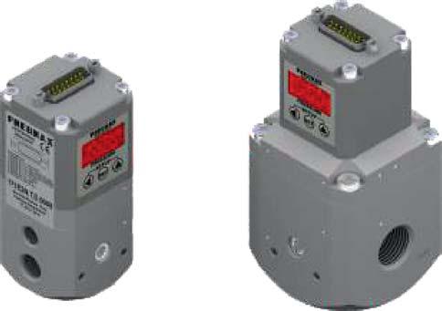
24 7_E2N. _. D.. _ PRESSURE RANGE : = - bar 5= - 5 bar 9= - 9 bar MANAGEMENT : C= Current signal (4-2 ma / -2 ma) T= Voltage signal (- V / -5 V / -5 V) Standard version External pressure feedback Exhaust downstream pressure when power supply is removed SIZE : = Size = Size 3= Size 3 53.F5. _. _ VARIANTS : = Only connector + casing IP65 3= Connector + cable, 3 metres 5= Connector + cable, 5 metres VERSION : = straight 9= output 9 7M5 23
25 7 Series 24

26
JOLLY2. Installation user s manual. 6 different operating modes selectable. version 3.3. DATA TO BE FILLED OUT BY THE INSTALLER (Page 1)
") ENGLISH ENGLISH ENGLISH ENGLISH Installation user s manual Warning! electrical scheme modified JANUARY 2005 version 3.3 JOLLY2 DATA TO BE FILLED OUT BY THE INSTALLER (Page 1) 6 different operating modes
ENGLISH ENGLISH ENGLISH ENGLISH Installation user s manual Warning! electrical scheme modified JANUARY 2005 version 3.3 JOLLY2 DATA TO BE FILLED OUT BY THE INSTALLER (Page 1) 6 different operating modes
Technical Data Sheet MF010-O-LC
 Technical Data Sheet MF010-O-LC - 1 - 1. Properties The oxygen measuring system MF010-O-LC determines the oxygen content in gas mixtures up to a temperature of 250 C. It is particularly suitable for the
CONSOLE-320 ENGLISH. 230A: CONSOLE-320 with cable data output Item 230B: CONSOLE-320 with cable + wireless radio data output
 CONSOLE-320 Item 230A: CONSOLE-320 with cable data output Item 230B: CONSOLE-320 with cable + wireless radio data output Table of contents 1. INTRODUCTION...2 1.1 Power supply...2 1.2 Connections...2 1.3
TR Electronic Pressure Regulator. User s Manual
 TR Electronic Pressure Regulator Page 2 of 13 Table of Contents Warnings, Cautions & Notices... 3 Factory Default Setting... 4 Quick Start Procedure... 5 Configuration Tab... 8 Setup Tab... 9 Internal
Roller AC Servo System
 Safely Instruction Roller AC Servo System HMI-15 User Manual Please read this manual carefully, also with related manual for the machinery before use the controller. For installing and operating the controller
Exercise 1: Control Functions
 Exercise 1: Control Functions EXERCISE OBJECTIVE When you have completed this exercise, you will be able to control the function of an asynchronous ripple counter. You will verify your results by operating
BUBBLER CONTROL SYSTEM
 BUBBLER CONTROL SYSTEM Description: The HDBCS is a fully automatic bubbler system, which does liquid level measurements in water and wastewater applications. It is a dual air compressor system with, air
Standard 1/4 compressor chiller/heat pump with heating recovery Manual version: /02/97
 Application program for Macroplus II Standard 1/4 compressor chiller/heat pump with heating recovery Manual version: 2.2-06/02/97 Program code: EP000EPDC0 Rif.: 17EM INDEX MAIN FEATURES...2 Hardware Description...2
Touch Screen Guide. OG-1500 and OG Part # T011
 Touch Screen Guide OG-1500 and OG-2000 Part # 9000000.T011 Effective 11/2010 External View Internal View 1. Transducer Banks 2. Oxygen Sensor 3. PLC These are the two manifolds with three (3) transducers
Operating instructions Electrical switching facility pco
 Operating instructions Electrical switching facility pco from software version V1.33 on TABLE OF CONTENTS 1. Before you start... 4 1.1 Brief description... 4 1.2 Using this manual... 4 2. pco integrated
Manual Weighingblock VB2 series and Uniscale
 Manual Weighingblock VB2 series and Uniscale Note: At page 8 in this manual you will find a short form instruction. Normally the only instruction shipped together with the Scale. Overview different ranges.
MANUAL KPS Pressure Control Valve
 TetraTec Instruments GmbH Gewerbestrasse 8 71144 Steinenbronn Deutschland E-Mail: info@tetratec.de Tel.: 07157/5387-0 Fax: 07157/5387-10 MANUAL Pressure Control Valve *** VERSION 1.0 *** Update: 17.11.2006
KEM Scientific, Inc. Instruments for Science from Scientists
 KEM Scientific, Inc. Instruments for Science from Scientists J-KEM Scientific, Inc. 6970 Olive Blvd. St. Louis, MO 63130 (314) 863-5536 Fax (314) 863-6070 E-Mail: jkem911@jkem.com Precision Vacuum Controller,
Measuring range Δp (span = 100%) Pa
 Pa") 4.4/ RLE 5: Volume-flow controller, continuous How energy efficiency is improved Enables demand-led volume flow control for the optimisation of energy consumption in ventilation systems. Areas of application
4.4/ RLE 5: Volume-flow controller, continuous How energy efficiency is improved Enables demand-led volume flow control for the optimisation of energy consumption in ventilation systems. Areas of application
CF8-W-Disp-CO. User manual. CO 2 / CO sensor with built-in general purpose controller
 User manual CF8-W-Disp-CO CO 2 / CO sensor with built-in general purpose controller General The IAQ-sensor product CF8-W-Disp-CO is used to measure indoor air carbon dioxide and carbon monoxide concentrations.
ACV-10 Automatic Control Valve
 ACV-10 Automatic Control Valve Installation, Operation & Maintenance General: The Archer Instruments ACV-10 is a precision automatic feed rate control valve for use in vacuum systems feeding Chlorine,
Stand-Alone Bubble Detection System
 Instruction Sheet P/N Stand-Alone Bubble Detection System 1. Introduction The Bubble Detection system is designed to detect air-bubble induced gaps in a bead of material as it is being dispensed. When
SAPCON. User Manual. Capacitance Continuous Level Indicator. . Introduction. . General Description. . Principle of Operation. .
 User Manual Capacitance Continuous Level Indicator Comprehensive User s Manual. Introduction. General Description. Principle of Operation. Specifications. Connection Diagrams. Quick Calibration Chart.
A4 Operation Manual. Fig.1-1 Controller Socket Diagram
 A4 Operation Manual Safety Instruction Please read this manual carefully, also with related manual for the machinery before use the controller. For installing and operating the controller properly and
Doc. no.dit om005 PRODUCT NAME. IO-Link/ELECTRO-PNEUMATIC REGULATOR. MODEL / Series / Product Number ITV*0*0-IO****-X395
 Doc. no.dit-69900-om005 PRODUCT NAME IO-Link/ELECTRO-PNEUMATIC REGULATOR MODEL / Series / Product Number ITV*0*0-IO****-X395 This is the operation manual for the IO-Link compliant ITV. For other contents
A4s Operation Manual
 A4s Operation Manual Safety Instruction Please read this manual carefully, also with related manual for the machinery before use the controller. For installing and operating the controller properly and
User Manual. asense VAV. CO 2 / temperature sensor with built-in general purpose controller
 Gas and Air Sensors User Manual asense VAV CO / temperature sensor with built-in general purpose controller General The IAQ-sensor product asense VAV is used to measure indoor air carbon dioxide concentration
Safety Manual. Process pressure transmitter IPT-1* 4 20 ma/hart. Process pressure transmitter IPT-1*
 Safety Manual Process pressure transmitter IPT-1* 4 20 ma/hart Process pressure transmitter IPT-1* Contents Contents 1 Functional safety 1.1 General information... 3 1.2 Planning... 4 1.3 Instrument parameter
UBEC 1AT. AUTO TANK Fill System Installation, Operation, & Setup Instructions
 Document Number: XE-ATA5PM-R1A UBEC 1AT AUTO TANK Fill System 08899155 Installation, Operation, & Setup Instructions Rev170906-EB-FRC PHYSICAL: 1302 WEST BEARDSLEY AVE ELKHART, IN 46514 WWW.ELKHARTBRASS.COM
Mass Flow Controller (MFC) for Gases
 for Gases") Mass Flow Controller (MFC) for Gases Type 8713 can be combined with... Direct flow measurement by MEMS- Technology for nominal flow rates from 1 ml N /min to 8 l N /min (N 2 ) High accuracy and repeatability
Mass Flow Controller (MFC) for Gases Type 8713 can be combined with... Direct flow measurement by MEMS- Technology for nominal flow rates from 1 ml N /min to 8 l N /min (N 2 ) High accuracy and repeatability
2/ Port G1/4
 CATALOGUE > Release 8.8 > Series ER100 digital electro-pneumatic regulators Series ER100 digital electro-pneumatic regulators Port G1/4 Compact design Digital display Analog and digital input Programmable
The HumiSys. RH Generator. Operation. Applications. Designed, built, and supported by InstruQuest Inc.
 The HumiSys RH Generator Designed, built, and supported by InstruQuest Inc. Versatile Relative Humidity Generation and Multi-Sensor System The new HumiSys with single or dual RH probes capabilities is
Application Notes. SLP85xD Load Cells
 Application Notes Load Cells Table of Contents 1 Introduction 3 2 Description of the Filling Cycle 4 3 Filling Optimization 7 4 Filling Monitor 8 4.1 Weight-Based Filling Monitor... 8 4.2 Time-Based Filling
Analogue and Digital Mass Flow Meters and Controllers for Gases MASS-STREAM
 Analogue and Digital Mass Flow Meters and Controllers for Gases MASS-STREAM M+W Instruments Your partner Key Facts M+W Instruments was founded in 1988 and has always specialised in thermal mass flow meters
Pegas 4000 MF Gas Mixer InstructionManual Columbus Instruments
 Pegas 4000 MF Gas Mixer InstructionManual Contents I Table of Contents Foreword Part I Introduction 1 2 1 System overview... 2 2 Specifications... 3 Part II Installation 4 1 Rear panel connections...
User Manual. asense miii. / CO sensor with built-in general purpose controller
 Gas and Air Sensors User Manual asense miii CO 2 / CO sensor with built-in general purpose controller General The IAQ-sensor product asense miii is used to measure indoor air carbon dioxide and carbon
Connections The C20B can be connected either using the Molex locking socket, or by connection to four plated through holes. The plated through
 E-MAIL: C20 Carbon Dioxide Sensor General Description The C20B is a carbon dioxide designed specifically for educational applications. The C20B provides fully temperature compensated readings of Carbon
PROPORTIONING VALVE. Model 150 INSTRUCTION MANUAL. March 2017 IMS Company Stafford Road
 PROPORTIONING VALVE Model 150 INSTRUCTION MANUAL March 2017 IMS Company 10373 Stafford Road Telephone: (440) 543-1615 Fax: (440) 543-1069 Email: sales@imscompany.com 1 Introduction IMS Company reserves
Service Test Unit for ROSS Proportional Valves RESK
 Service Unit for Proportional Valves Page 1 Technical Description ROSS 04.08.2015 Service Test Unit for ROSS Proportional Valves Technical Description V 1.0 / 2015 RESK 4591.40 For all Prop Valve Models
EPR High Precision 3000 psi Electronic Pressure Controller Accurate to 0.25% of full scale
 EPR-3000 High Precision 3000 psi Electronic Pressure Controller Accurate to 0.25% of full scale General Specifications PRECISE CONTROL UP TO 3000 PSI The Equilibar EPR-3000 dual valve pressure controller
Built-in Purge Control Functions
 Built-in Purge Control Functions Why clean a sensor? As the velocity sensor was calibrated clean, operating it clean also preserves the best calibration. Any build up of material on a thermal sensor tends
COMPRESSOR PACK SUCTION CONTROLLER TYPE: LP41x
 Electrical Installation Requirements Care should be taken to separate the power and signal cables to prevent electrical interference and possible damage due to inadvertent connection. SUPPLY E L N LN2
Hydro-Control V User Guide
 Hydro-Control V User Guide Hydronix Part no: HD0193 Version 2.3.0 Revision date: July 2006 1 COPYRIGHT Neither the whole or any part of the information contained in nor the product described in this documentation
SCIENTIFIC DATA SYSTEMS, INC. Depth Tension Line Speed Panel. DTLS Manual
 SCIENTIFIC DATA SYSTEMS, INC. Depth Tension Line Speed Panel DTLS Manual This document contains proprietary information. Copyright 2015 Scientific Data Systems, Inc. All rights reserved. 1 Depth Tension
Standard Chiller 1/4 compressors Manual version: /10/96
 Application program for Macroplus II Standard Chiller 1/4 compressors Manual version: 1.4-18/10/96 Program code: EP000ECH02 Rif.: 68EM Contents 0$,1)($785(6 HARDWARE...2 FUNCTIONS OF THE SYSTEM...3 PROTECTIONS...3
HumiSys HF High Flow RH Generator
 HumiSys HF High Flow RH Generator Designed, built, and supported by InstruQuest Inc. Versatile Relative Humidity Generation and Multi-Sensor System The HumiSys HF is a high flow version of the previously
571 Series Medical TM. IntelliSwitch Electronic Switchover
 ADI 9505-H 571 Series Medical TM IntelliSwitch Electronic Switchover INSTALLATION AND OPERATING INSTRUCTIONS Carefully Read These Instructions Before Operating Carefully Read These Controls Corporation
USER MANUAL. Intelligent Diagnostic Controller IDC24-A IDC24-AF IDC24-AFL IDC24-F IDP24-A * IDP24-AF * IDP24-AFL * IDP24-F * 1/73
 USER MANUAL Intelligent Diagnostic Controller IDC24-A IDC24-AF IDC24-AFL IDC24-F IDP24-A * IDP24-AF * IDP24-AFL * IDP24-F * *) Require software ID: DID-SW-001 1/73 Table of contents 1 General... 3 1.1
Datasheet: K-30 ASCII Sensor
 Datasheet: K-30 ASCII Sensor The K30 ASCII sensor is a low cost, infrared and maintenance free transmitter module intended to be built into different host devices that require CO2 monitoring data. The
EPP4 Pressure Regulator Basic G 1/4"
 EPP4 Pressure Regulator Basic G 1/4" Flow Curve 1/4" Dimensions Outlet pressure - bar 9 8 7 6 5 4 3 2 1 0 0 20 40 60 70 80 100 120 Flow rate - Nm 3 /h The male connector adopted on the EPP4 is a standard
Mass Flow Controller (MFC) for Gases
 for Gases") Mass Flow Controller (MFC) for Gases Direct flow measurement with CMOSens technology for nominal flow rates from 0 ml N to 0 l N High accuracy and reproducibility Ingress protection IP Type can be combined
Mass Flow Controller (MFC) for Gases Direct flow measurement with CMOSens technology for nominal flow rates from 0 ml N to 0 l N High accuracy and reproducibility Ingress protection IP Type can be combined
Mitos Fluika Pressure and Vacuum Pumps Datasheet
 Unit 1, Anglian Business Park, Orchard Road, Royston, Hertfordshire, SG8 5TW, UK T: +44 (0)1763 242491 F: +44 (0)1763 246125 E: sales@dolomite-microfluidics.com W: www.dolomite-microfluidics.com Dolomite
Wickets Administrator
 Wickets Administrator Software For Managing Stored Value Wickets 01/08/2008 Product Details And Operating Instructions Overview This page describes each major function of Wickets Administrator in detail.
Section 2 Proportional Quick Exhaust
 V A L V E S Section 2 Proportional Quick Exhaust OPERATION OF THE PQE 1. The pilot operated regulator and the PPC5C are both fed from a common inlet. 2. The out port of the PPC5C sends pressure to the
AC : MEASUREMENT OF HYDROGEN IN HELIUM FLOW
 AC 2010-2145: MEASUREMENT OF HYDROGEN IN HELIUM FLOW Randy Buchanan, University of Southern Mississippi Christopher Winstead, University of Southern Mississippi Anton Netchaev, University of Southern Mississippi
(AS AT 31 st MARCH, 2002)
") ACACA PROTOCOL 2000 (AS AT 31 st MARCH, 2002) ACACA PROTOCOL 2000 INCLUDES (A) CODE OF PRACTICE FOR MANUFACTURERS AND/OR SUPPLIERS OF COMMERCIAL AIR COMPRESSORS AND METHOD FOR DETERMINING (B) RECIPROCATING
ACACA PROTOCOL 2000 (AS AT 31 st MARCH, 2002) ACACA PROTOCOL 2000 INCLUDES (A) CODE OF PRACTICE FOR MANUFACTURERS AND/OR SUPPLIERS OF COMMERCIAL AIR COMPRESSORS AND METHOD FOR DETERMINING (B) RECIPROCATING
Design Envelope Booster. Sequence of operation
 Design Envelope Booster Sequence of operation File No: 62.835 Date: february 11, 2015 Supersedes: 62.835 Date: july 11, 2014 sequence of operation Design Envelope Booster 2 general The packaged domestic
Neles ValvGuard VG9000H Rev 2.0. Safety Manual
 Neles ValvGuard VG9000H Rev 2.0 Safety Manual 10SM VG9000H en 11/2016 2 Neles ValvGuard VG9000H Rev 2.0 Safety Manual Table of Contents 1 General information...3 1.1 Purpose of the document... 3 1.2 Description
Smart Water Application Technologies (SWAT)
") Smart Water Application Technologies (SWAT) Turf and Landscape Irrigation Equipment PRESSURE REGULATING SPRAY HEAD SPRINKLERS Equipment Functionality Test Testing Protocol Version 3.0 (May 2012) Developed
Smart Water Application Technologies (SWAT) Turf and Landscape Irrigation Equipment PRESSURE REGULATING SPRAY HEAD SPRINKLERS Equipment Functionality Test Testing Protocol Version 3.0 (May 2012) Developed
955730_1 4/17/18. FlowSense Operator s Guide For Gen2 20/20 SeedSense Displays
 955730_1 4/17/18 FlowSense Operator s Guide For Gen2 20/20 SeedSense Displays Contents System Setup and Operation...3 Configuring Monitor for FlowSense...3 FlowSense Setup...4 Liquid Alerts...8 Monitoring
Specifications and information are subject to change without notice. Up-to-date address information is available on our website.
 www.smar.com Specifications and information are subject to change without notice. Up-to-date address information is available on our website. web: www.smar.com/contactus.asp LD302 - AssetView HMI LD302
EXPERIMENT 1 AIR PRESSURE CONTROL SYSTEM
 EXPERIMENT 1 AIR PRESSURE CONTROL SYSTEM 1.0 OBJECTIVE To study the response of gas pressure control using PID controller. 2.0 INTRODUCTION TO THE APPARATUS a) The process plant consists of two air vessels
Mass Flow Controller (MFC) for Gases
 for Gases") Mass Flow Controller (MFC) for Gases Bypass MFC with capillary technology for nominal flow rates from 5 ml N /min to 15 l N /min Applicable for aggressive gases Compact design and digital communication
Mass Flow Controller (MFC) for Gases Bypass MFC with capillary technology for nominal flow rates from 5 ml N /min to 15 l N /min Applicable for aggressive gases Compact design and digital communication
Location of CC Number if not located with the identification:
 This checklist is used for Technical Policy U. Evaluating electronic digital indicators submitted separate from a measuring element. This section is intended for lab testing only. Is permanence necessary?
AHE58/59 AC Servo System
 AHE58/59 AC Servo System HMI-12 User Manual Safely INstruction Please read this manual carefully, also with related manual for the machine head before use. For perfect operation and safety, installing
Air Bubbler Depth Gauge DG2200 Installation and Reference Manual
 Air Bubbler Depth Gauge DG2200 Installation and Reference Manual Rev. 3.2.2 06/2011 Installation and Reference Manual Page 2 Contents Chapter 1: Installation and Overview... 3 1.1 DG2200 Location Diagram...
Digital Mass Flow Meters and Controllers for Gases
 Digital Mass Flow Meters and Controllers for Gases A Bronkhorst company. M+W Instruments. Your specialists for inline measurement WORTH KNOWING M+W Instruments was founded in 1988 and has always specialised
BAROMETER PRESSURE STANDARD PRESSURE CONTROLLER
 BAROMETER PRESSURE STANDARD PRESSURE CONTROLLER Features ±0.01% FS Measurement & Control Accuracy ±0.001% /ºC Thermal Stability Pressure Ranges from ±1 psid to 1200 psia Applications Barometric Measurement
Electropneumatic Positioner and Pneumatic Positioner Type 3760 JIS
 Electropneumatic Positioner and Pneumatic Positioner Type 3760 Application Single-acting positioners for direct attachment to pneumatic control valves. Supplied with an electric input signal of 4 to 20
2600T Series Pressure Transmitters Plugged Impulse Line Detection Diagnostic. Pressure Measurement Engineered solutions for all applications
 Application Description AG/266PILD-EN Rev. C 2600T Series Pressure Transmitters Plugged Impulse Line Detection Diagnostic Pressure Measurement Engineered solutions for all applications Increase plant productivity
D10S/D20S Wall/Post Mount Inflator Quick Start Manual
 PART NUMBER SERIAL NUMBER D10S/D20S Wall/Post Mount Inflator Quick Start Manual Please read and save these instructions. Read carefully before attempting to assemble, install, operate or maintain the product
AX5000 Operational Manual
 MIYACHI AMERICA CORPORATION The World Leader in Hermetic Sealing Systems AX5000 Operational Manual 0 Document #107-00092-001 Dec, 2013 AX5000 Operational Manual Miyachi America Corporation 1820 S. Myrtle
Cell Injury Controller II (CIC II)
") Cell Injury Controller II (CIC II) CIC II Operation Manual Contents Introduction 2 Quick-Start 2 Theory of Operation 3 Injury Measurement Method 3 Components 4 External Requirements 4 Front Panel 5 Rear
Cell Injury Controller II (CIC II) CIC II Operation Manual Contents Introduction 2 Quick-Start 2 Theory of Operation 3 Injury Measurement Method 3 Components 4 External Requirements 4 Front Panel 5 Rear
Cover Page for Lab Report Group Portion. Pump Performance
 Cover Page for Lab Report Group Portion Pump Performance Prepared by Professor J. M. Cimbala, Penn State University Latest revision: 02 March 2012 Name 1: Name 2: Name 3: [Name 4: ] Date: Section number:
SECTION 2 SMART PAYOUT MANUAL SET FIELD SERVICE MANUAL
 SECTION 2 SMART PAYOUT MANUAL SET FIELD SERVICE MANUAL Innovative Technology assume no responsibility for errors, omissions, or damages resulting from the use of information contained within this manual.
Domino DUEMMEGI. Domino. Communication Interface DFTS User s Manual. Release September 2007
 Domino Domino Communication Interface DFTS User s Manual Release 2.3 - September 2007 srl Via Longhena 4-20139 MILANO Tel. 02/57300377 - FAX 02/55213686 Domino - DFTS: User s Manual R.2.3 Index 1- INTRODUCTION...3
The Ins and Outs of I/P Transducers
 The Ins and Outs of I/P Transducers By Mark B. Levine, ControlAir Inc. General description I/P transducers are versatile instruments that use an electrical control signal to proportionally regulate gas
OC508 Programmable mv Calibrator
 OC508_GBM_201609 OC508 Programmable mv Calibrator Owner s Manual Orbit Controls AG Zürcherstrasse 137 CH8952 Schlieren - ZH orbitcontrols.ch OC508 Programmable mv Calibrator Selection of DIN Thermocouples
Terminal block. D sub-connector
 Spd Series variation ol method Solenoid valve EVD-1 EVD-3 EVR EV21V EVS2 EVL MEVT Model Electro pneumatic regulator Functions include pressure and error display and direct memory. The 1-bit parallel model
Operating Instructions EB EN. Series 373x Electropneumatic Positioner Type 373x-5 EXPERT + with FOUNDATION fieldbus communication
 Series 373x Electropneumatic Positioner Type 373x-5 EXPERT + with FOUNDATION fieldbus communication Fig. 1 Valve diagnostics with TROVIS-VIEW Operator Interface Operating Instructions EB 8388-5 EN Firmware
Electropneumatic Positioner and Pneumatic Positioner Type 3760 JIS
 Electropneumatic Positioner and Pneumatic Positioner Type 3760 Application Single-acting positioners for direct attachment to pneumatic control valves. An electric standardized signal of 4 to 20 ma or
Table 1: Safety Function (SF) Descriptions
 Descriptions") Table 1: Safety Function (SF) Descriptions NOTE: all safety s are individual safety s TUV NORD? Pressing the Estop PB on the pendant 1 or the Estop (if using the Estop Safety Input configured for Estop)
Table 1: Safety Function (SF) Descriptions NOTE: all safety s are individual safety s TUV NORD? Pressing the Estop PB on the pendant 1 or the Estop (if using the Estop Safety Input configured for Estop)
BUBBLER CONTROL SYSTEM
 BUBBLER CONTROL SYSTEM Description: The LDBCS is a fully automatic bubbler system, which does liquid level measurements in water and wastewater applications. It is a dual air compressor system with, air
APA software instruction manual
 1. Starting the program In order to start the control software for the APA device press APAxx shortcut located on the desktop of the supplied computer. XX corresponds to the current software version. When
CCT-7320/ROC-2313 Reverse Osmosis Controller
 CCT-7320/ROC-2313 Reverse Osmosis Controller 1 General The instrument is a combined control instrument of a reverse osmosis controller and an on-line conductivity instrument. It can perform the operation
THE SOUNDBEAM 2 HANDBOOK PART 2 STEP BY STEP
 THE SOUNDBEAM 2 HANDBOOK PART 2 STEP BY STEP THE SOUNDBEAM PROJECT JANUARY 2002 CONTENTS 1. SET-UPS p. 5 1.1. To Select a Set-up p. 6 1.2. To Save a Set-up p. 8 1.3. To Copy the Modified Settings of a
Control Units for Oil+Air Lubrication
 Control Units for Oil+Air Lubrication 1-1700-3-US Universal Control Unit The control units described in this leaflet are used for timeor pulse-dependent control of oil+air systems. The overview shows the
Overview. Front Panel: Keypad and Display
 Overview The GA-200B is an analyzer that integrates a gas sampling system with sensors to measure and display the concentrations of oxygen and carbon dioxide in a sample as the percentage of a gas in the
TH-1800-T TRX-700-CNG Converter
 TH-1800-T TRX-700-CNG Converter low detector The CNG fuel gas flowmeter is so accurate as to meet a demand of measuring the CNG directly by making the most use of our well-established mini-thermal flowmeter
MASS FLOW SYSTEMS MASS FLOW MEASURING, CONTROLLING AND BLENDING SYSTEMS
 MASS FLOW SYSTEMS MASS FLOW MEASURING, CONTROLLING AND BLENDING SYSTEMS Using state-of-the-art measuring and microprocessor technologies, Advanced has assembled a series of systems which can measure mass
SomnoSuite FAQ. Setup. Calibration 4. What are the calibration requirements for the SomnoSuite? Settings
 SomnoSuite FAQ V1.3 January 2015 Setup 1. How do I connect the SomnoSuite to my oxygen source? 2. Is there a way to speed up the downward movement of the pusher block when setting the empty position? 3.
C1960. Multi-recipe profile recorder/controller. Measurement made easy
 ABB ME ASUREMENT & A NALY TI C S PROGR AMMING GU I DE I M/C1900 - FG REV. B C1960 Circular chart recorder/controller Multi-recipe profile recorder/controller Measurement made easy C1900 circular chart
PRODUCT MANUAL. Diver-MOD
 PRODUCT MANUAL Diver-MOD Contents 1 Introduction... 1 1.1 Scope and Purpose... 1 1.2 Features... 1 1.3 System Overview... 1 1.4 Specifications... 2 2 Getting Started... 2 2.1 Supported Equipment... 2 2.2
Installing a Probe. Typical Installation
 for hazardous locations. Prior to any installation in a Classified Hazardous Location, verify installation methods by the Control Drawing referenced on the product s name tag 2. The Feed Through Assemblies
FIO > Five In One The SMART regulator
 FIO > Five In One The SMART regulator Indirect Flow Measurement Outlet Pressure Control Flow Limitation Remote Monitoring End-User Management www.mvandc.com Integrated remote controlled regulator FIO >
The Univentor 1250 Anaesthesia Unit
 THE UNIVENTOR 1200/1250 ANAESTHESIA UNIT The Univentor 1250 Anaesthesia Unit TABLE OF CONTENTS EDITION 1 Section 1 - WARRANTY & SERVICE 1.1. WARRANTY 2 1.2. DAMAGED SHIPMENTS 2 1.3. SERVICE 2 Section 2
Test and Adjustment Instructions Compressed Air Processing System Air Processing Unit (APU)
") Test and Adjustment Instructions Compressed Air Processing System Air Processing Unit () 1st issue 8150004983 815 000 498 3 This document is not covered by a revision service. New versions can be found
Test and Adjustment Instructions Compressed Air Processing System Air Processing Unit () 1st issue 8150004983 815 000 498 3 This document is not covered by a revision service. New versions can be found
Race Screen: Figure 2: Race Screen. Figure 3: Race Screen with Top Bulb Lock
 Eliminator Competition Stand Alone Mode - Instruction Manual Main Menu: After startup, the Eliminator Competition will enter the Main Menu. Press the right/left arrow buttons to move through the menu.
Troubleshooting Guide: 640 Pediatric Exam Table with Midmark Scale
 Troubleshooting Guide: 640 Pediatric Exam Table with Midmark Scale Contents Description Refer To: Scale Troubleshooting Chart Troubleshooting Error Codes Error Messages Adjustments / Repair Procedures
Description of Device Parameters Proline Prowirl 200 HART. Vortex flowmeter. Products Solutions Services. Main menu Language.
 GP01019D/06/EN/02.15 71308256 Valid as of version 01.02.zz (Device firmware) Products Solutions Services of Device Parameters Proline Prowirl 200 HART Vortex flowmeter XXXXXXXXX 20.50 Main menu 0104-1
SDI mA Pressure Transducer (Submersible + Dry) Model WL2100 Operating Manual
 Model WL2100 Operating Manual") SDI-12 + 4-20mA Pressure Transducer (Submersible + Dry) Model WL2100 Operating Manual (Submersible) WL2100W (Dry) WL2100D QUALITY SYSTEM ISO: 9001 CERTIFIED HYQUEST SOLUTIONS PTY LTD 48-50 Scrivener St,
SDI-12 + 4-20mA Pressure Transducer (Submersible + Dry) Model WL2100 Operating Manual (Submersible) WL2100W (Dry) WL2100D QUALITY SYSTEM ISO: 9001 CERTIFIED HYQUEST SOLUTIONS PTY LTD 48-50 Scrivener St,
Intelligent SUNTEX DC-5310(RS) Dissolved Oxygen Transmitter
 Dissolved Oxygen Transmitter") Intelligent SUNTEX DC-5310(RS) Dissolved Oxygen Transmitter Overview C % ppm 4~20mA Analog Output ppb Power Supply 100~240 VAC mg/l Dimensions 96 x 96 x 132mm RS-485 Digital Output (for DC-5310-RS only)
Intelligent SUNTEX DC-5310(RS) Dissolved Oxygen Transmitter Overview C % ppm 4~20mA Analog Output ppb Power Supply 100~240 VAC mg/l Dimensions 96 x 96 x 132mm RS-485 Digital Output (for DC-5310-RS only)
Series 3730 and Series 3731 EXPERTplus Valve Diagnostics with Partial Stroke Test (PST)
") Series 3730 and Series 3731 EXPERTplus Valve Diagnostics with Partial Stroke Test (PST) Application Positioner firmware for early detection of control valve faults giving maintenance recommendations. Valid
Series 3730 and Series 3731 EXPERTplus Valve Diagnostics with Partial Stroke Test (PST) Application Positioner firmware for early detection of control valve faults giving maintenance recommendations. Valid
Project Title: Pneumatic Exercise Machine
 EEL 4924 Electrical Engineering Design (Senior Design) Preliminary Design Report 27 January 2011 Project Title: Pneumatic Exercise Machine Team Members: Name: Gino Tozzi Name: Seok Hyun (John) Yun Email:
Mass Flow Meter (MFM) for gases
 for gases") Mass Flow Meter (MFM) for gases Type can be combined with Inline MFM for nominal flow rates from 25 l N /min to 1,500 l N /min; 1/4 to 3/4 High accuracy Fast settling time Fieldbus option Special version
Mass Flow Meter (MFM) for gases Type can be combined with Inline MFM for nominal flow rates from 25 l N /min to 1,500 l N /min; 1/4 to 3/4 High accuracy Fast settling time Fieldbus option Special version