Copyright, 2005 GPM Hydraulic Consulting, Inc.
|
|
|
- Denis Junior Walker
- 6 years ago
- Views:
Transcription


1 Troubleshooting and Preventive Maintenance of Hydraulic Systems Learning to Read the Signs of Future System Failures Instructed by: Al Smiley & Alan Dellinger Copyright, 2005 GPM Hydraulic Consulting, Inc.
2 Hydraulic Pumps Fixed Displacement Pumps The GPM of the fixed displacement pump can not be varied.
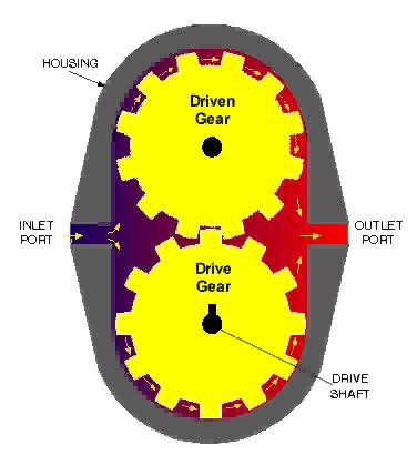
3 Gear Pump
4 Relief Valves and Fixed Displacement Pumps Provides a flow path for the pump volume back to tank Limits the maximum system pressure

5 Relief Valve
6 Setting the Relief Valve in a Fixed Observe the pressure while operating. Displacement Pump Circuit Open allflow controls and isolate any accumulators. Set the relief valve 200 PSI above the maximum operating pressure
7 Setting the Relief Valve in a Fixed Close the Hand Valve. Displacement Pump Circuit Adjust the relief to 1200 PSI. (For this example) Turn the system off, open the hand valve and remove the gauge.
8
9 Troubleshooting Fixed Displacement Pump Circuits
10 Sound Checks Cavitation is the formation and collapse of air cavities in the liquid. A pump that is cavitating will put out a reduced flow until it destroys itself. Cavitation is caused by: Oil viscosity too high Plugged suction filter Electric motor RPM too high
11 Aeration Aeration occurs when outside air enters the suction side of the pump. Aeration is caused by: Air leak in the suction line Bad shaft seal on a fixed displacement pump Fluid level too low Improper Installation: Coupling is not properly aligned Wrong shaft rotation
12 Checking the Fixed Displacement Pump Check the pump housing for heat
13 Check the current draw on the electric drive motor HP = GPM X PSI X If the pump is bypassing and the GPM output is lower, then the drive motor s current draw will also be lower
14 Checking the Fixed Displacement Pump Through the Relief Valve Turn the relief valve CCW and observe the flow Gradually turn the relief CW and observe the flow
15
16 Variable Displacement Pumps Variable Displacement Pumps are used when the volume requirements change in the system

17 Pressure Compensating Piston Pump
18 Pressure Compensating Piston Pump

19 Pressure Compensating Piston Pump Case Drain Compensator

20 Pump Compensator Spring Spool
21 Case Drain Most Variable Displacement Pumps have an external case drain piped directly back to tank. Normal bypassing is 1-3% of the total pump volume.
22 Pressure Compensating Piston Pump
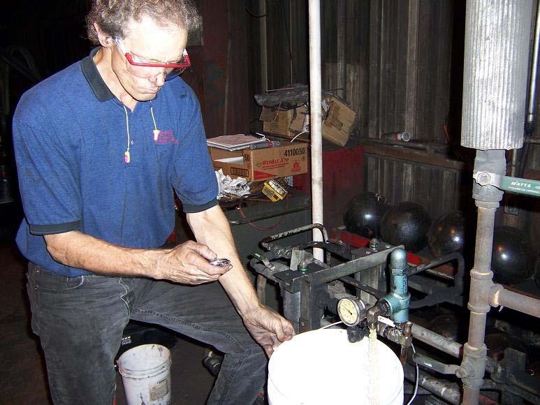
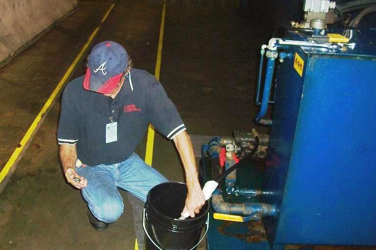
23 Case Drain Flow Method #1 There are two methods of checking case drain flow: Run the case drain flow into a container of known size and time it
24
25 Case Drain Flow Method #2 A flow meter may be permanently installed in the case drain line.

26 Case Drain Line Cooler
27 Pressure Compensating Piston Pump
28 Pressure Compensating Pump Example
29 Pressure Compensating Pump Example
30 Pressure Compensating Pump Example
31 Systems With Relief Valves The purposes of a relief valve in a pressure compensating pump system are: Absorb pressure spikes Operate as an extreme safety device The only time the relief valve should open is when the pressure rises above the compensator setting.
32
33 Adjustment Procedure Observe the system to find the maximum operating pressure Establish a deadhead condition Turn the relief valve fully CCW Turn the compensator fully CW

34 Adjustment Procedure Turn the relief valve CW to 1450 PSI Turn the compensator to 1200 PSI
35 Relief Set Below Compensator If the relief valve is set below the compensator, the pump will act as a fixed displacement pump. Heat will be generated!
36 Calculating Heat & Electrical Power HP = GPM X PSI X = 30 X 1450 X = 25 HP 746 Watts = 1 Horsepower Electrical Power = 746 X 25 = 18,650 Watts
37 Accumulators Hydraulic accumulators are used to store pressurized fluid
38 Bladder Accumulator
39 Piston Accumulator Piston Accumulator

40
41 Accumulators Accumulators are used for ONE of two purposes depending upon the PRECHARGE Supply additional oil flow to the system at a very fast rate Absorb shock


42 Accumulators Dry Nitrogen is used to precharge the top portion of an accumulator 1% Argon and other gases 21% Oxygen 78% Nitrogen
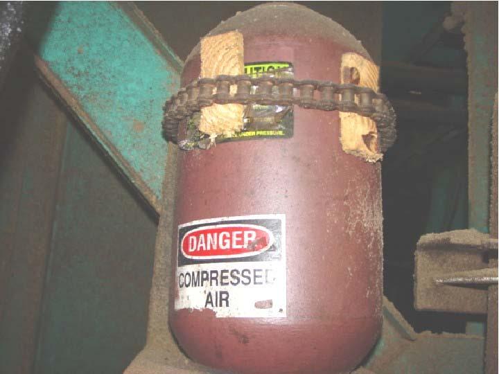
43 Accumulators NEVER use Oxygen or Compressed Air to precharge an accumulator! Rule of Thumb - Precharge to onehalf of the maximum system pressure
44 1000 PSI Precharge 1 0 PSI System Pressure PSI Compensator Setting

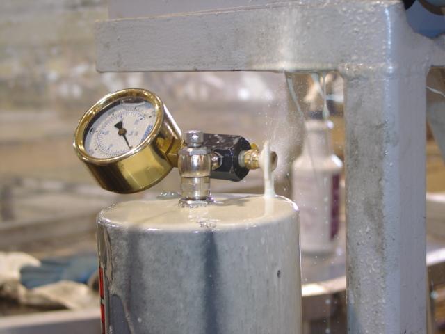
45 Using the Charging Rig Gauge Gas Chuck Handle Nitrogen Bottle Connection Bleeder Valve
46
47 Checking the Precharge Hydraulically 2000 Dump Valve Closed PSI Pressure Locked in System 2000 PSI Pump turned off
48 Checking the Precharge Hydraulically Dump Valve Open Pressure slowly drops to precharge, then immediately to 0 PSI

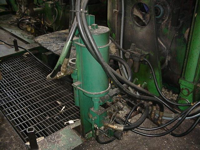
49 Types of Accumulators Piston Accumulators
50 Example Circuit 1000 PSI 1/4 Dump Valve (Open when the power is turned off) Isolation Valve 2000 PSI
51 Example Circuit 2000 PSI 2000 PSI 1/4 Dump Valve (Closed) Isolation Valve 2000 PSI Power On
52 Example Circuit 1800 PSI 1/4 Dump Valve (Closed) Isolation Valve 2000 PSI Extend Cylinder

53 Checking the Piston Accumulator 2000 PSI 2000 PSI System pressure should build to the compensator setting whenever actuators are not cycling

54 Checking the Piston Accumulator System pressure should not drop more than PSI when the directional valve opens 1800 PSI
55 Checking the Piston Accumulator Heat should be felt from here to here: Piston Travel

56 Checking the Piston Accumulator 1000 PSI Dropping to a very LOW pressure usually indicates an accumulator problem 100 PSI
57 Overcharged Heat Piston Movement

58 Oil Bypasses Around Piston Overcharged
59
60 Piston Removal With the pump on, open the #3 bleeder valve on the charging rig Close the #1 isolation valve Open the #2 manual dump valve Remove the charging rig and the top of the accumulator 3 2 1

61 Leak Paths for Nitrogen Undercharged

62 Undercharged Hydraulic pressure drives piston near the top Heat
63 Bladder Accumulator Poppet Valve
64
65
66

67 Bladder Accumulator Poppet Valve

68 Bladder Accumulator Poppet Valve

69 Bladder Accumulator Poppet Valve

70 Checking The Bladder Accumulator Heat should be felt between these two points
71 Checking The Bladder Accumulator If no heat is felt on the bladder accumulator, then one of two things has happened: The precharge is above the maximum system pressure The bladder is ruptured The nitrogen has leaked out of the bladder
72 Accumulator Dump Valves ANY circuit using an accumulator MUST have some method of bleeding the pressure down when the system is turned off Prior to working on the system, you should VERIFY that the pressure is bled down by observing the gauge
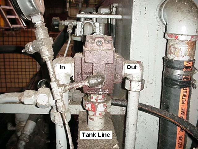
73 Manual Dump Valve
74
75 Solenoid Operated Dump Valve
76
77 Tolerances In Components Tolerances in hydraulic pumps and valves: 5-8 microns ( ) Tolerances inside servo valves: 3 microns (.0001 )
78 Sources of Contamination New oil leaving the refinery is relatively clean By the time it reaches your mill it meets a micron standard Oil should always be filtered prior to entering the reservoir
79 Built In Contamination When a system is first built and installed, contamination may be in the form of: Metal Chips Dirt Sand Pipe Sealant Burrs Dust Weld Splatter Paint
80 Ingressed Contamination There are four ways contamination can enter the system from the outside: Breather Cap Access Plates Hose and Component Replacement Cylinder Seals

81 Fluid Sampling The biggest problem in hydraulic systems is CONTAMINATION The key to controlling it is through an effective fluid sampling and filter maintenance program Sample Bottle

82 Oil Analysis The size and number of particles taken from 1ml of the sample are measured by a particle counter
83 ISO Cleanliness Code Recommended Servo Level is 14/11 System 1 passes with a level of 13/11 System 2 fails with a level of 16/14

84 Filter Selection Filters are selected by a Beta rating - the ratio of the number of particles upstream of the filter versus the number of particles downstream of a specific size Fluid entering and fluid leaving the filter is measured with a particle counter

85 Beta Rating 2 3m particles in β 3 = 2 1 3m particle out

86 Beta Rating 75 10m particles in β 10 = % Efficient 1 10m particle out Hydraulic systems require a beta rating of 75 to 100
87 Filter Placement There are primarily three locations for filters in the system (other than the suction strainer): Pressure Line Separate Recirculating System Return Line
88 Pressure Line Filter Upstream of ANY Servo Valve
89 Pressure Line Filter Downstream of a Fixed Displacement Pump operating at pressures exceeding 2250 PSI
90 Pressure Line Filter Downstream of a Variable Displacement Pump operating at pressures exceeding 1500 PSI
91 Return Line Filter
92 Separate Recirculating System
93 Leakage Control Problems with leaks: Expensive -at $3.00 a gallon, one leak that drips one drop per second will cost: $3.38 a day $102 a month $1225 a year Unsafe - dangerous conditions Environmentally Hazardous - EPA setting stricter standards and penalties
94 Causes of Leaks The main reason hydraulic systems leak is because of a bad installation Use the proper schedule of pipe Schedule 40 for suction and return lines Schedule 80 or 160 for pressure lines Apply sealant properly

95 Proper Clamping Hose 5 5 6

96 Socket Weld Flanges Weld PIPE O-Ring
97 Hose Installation Proper Crimping Proper Length Protective Sleeves
98 Drain Lines Case drain lines should be piped directly back to tank Below Fluid Level
99 Other Causes of Leaks Pressure settings and shock - pressures set too high result in excess force. Absorbed by the system, excess force shows up as leaks Contamination - Cylinder rod seals are not 100% efficient. In unfriendly environments, a protective cover or boot should be used
100 Thank You For Attending! Copyright, 2005 GPM Hydraulic Consulting, Inc.
Hydraulic Reliability & Preventive Maintenance Report
 Hydraulic Reliability & Preventive Maintenance Report The following is a report of the test, procedures and recommendations for the in-plant press. This information was recorded on May 10 th and 11 th,
Proper Pump Installation Practices
 Proper Pump Installation Practices 80-779, Rev. 10/08 There is a Reason Every Unit Comes With This Bright Orange Tag! Proper Alignment and Coupling Installation Do Not Drive Coupling Onto Shaft Pump Alignment
Unit 24: Applications of Pneumatics and Hydraulics
 Unit 24: Applications of Pneumatics and Hydraulics Unit code: J/601/1496 QCF level: 4 Credit value: 15 OUTCOME 2 TUTORIAL 9 ACCUMULATORS The material needed for outcome 2 is very extensive so there are
Lesson 6: Flow Control Valves
 : Flow Control Valves Basic Hydraulic Systems Hydraulic Fluids Hydraulic Tank Hydraulic Pumps and Motors Pressure Control Valves Directional Control Valves Flow Control Valves Cylinders : Flow Control
ACCUMULATOR OPERATING & MAINTENANCE INSTRUCTIONS
 ACCUMULATOR OPERATING & MAINTENANCE INSTRUCTIONS READ ALL INSTRUCTIONS PRIOR TO INSTALLATION AND OPERATION TO AVOID POSSIBLE INJURY Warning: Always consider any accumulator to contain pressure until proven
Contents. Catalog HY /US Load and Motor Control Valves SERIES CAVITY DESCRIPTION FLOW PRESSURE PAGE NO. LPM/GPM BAR/PSI
 Load and Motor Control Contents SERIES CAVITY DESCRIPTION FLOW PRESSURE PAGE NO. LPM/GPM BAR/PSI STANDARD PILOT ASSISTED CB101... C10-3... Load Control Cartridge Valve...45/12... 380/5500... 5-6 MHC-010-S***
COMPRESSOR REPLACEMENT PROCEDURE (R-134A)
") 372 ROUTE 4 BARRINGTON, NH 03825 USA TEL (603) 868-5720 FAX (603) 868-1040 1-800-435-6708 COMPRESSOR REPLACEMENT PROCEDURE (R-134A) [ ] If possible operate the compressor with proper charge for 5 minutes
372 ROUTE 4 BARRINGTON, NH 03825 USA TEL (603) 868-5720 FAX (603) 868-1040 1-800-435-6708 COMPRESSOR REPLACEMENT PROCEDURE (R-134A) [ ] If possible operate the compressor with proper charge for 5 minutes
Hydraulics. Hydraulic Pressure Control
 Hydraulics Hydraulic Pressure Control Direct Acting Pressure Relief Valve Normally Closed: Pilot Operated Relief Valve (Compound/ two stage) Small pilot relief valve + Main relief valve Pilot Operated
ANTI SHOCK RELIEF VALVE
 ANTI SHOCK RELIEF VALVE Wheeler Road Coventry CV3 4LA England Brüsseler Allee 2 D-41812 Erkelenz Tel. +44(0)2476-217-400 Fax +44(0)2476-217-488 Tel. +49(0)24 31-80 91-0 Fax +49(0)24 31-80 91-19 www.sunhydraulics.com
Target Cleanliness Worksheet. Systemic Contamination Control
 Target Cleanliness Worksheet Systemic Contamination Control Target Cleanliness Worksheet 1. SET A TARGET Eaton Recommended Cleanliness Code Chart PUMPS
FLUID POWER FLUID POWER EQUIPMENT TUTORIAL ACCUMULATORS. This work covers part of outcome 2 of the Edexcel standard module:
 FLUID POWER FLUID POWER EQUIPMENT TUTORIAL ACCUMULATORS This work covers part of outcome 2 of the Edexcel standard module: UNIT 21746P APPLIED PNEUMATICS AND HYDRAULICS The material needed for outcome
HPB25 Hydraulic Paving Breaker
 INSTRUCTION MANUAL HPB25 Hydraulic Paving Breaker Read and understand all of the instructions and safety information in this manual before operating or servicing this tool. Register this product at www.greenlee.com
E 328 E 498 Tank top mounting Connection up to G1½ and SAE 2 Nominal flow rate up to 600 l/min
 Return-Suction Filters E 8 E 98 Tank top mounting Connection up to G½ and SE Nominal flow rate up to 6 l/min Description pplication For operation in units with hydrostatic drives, when the return flow
E 328 E 498 Tank top mounting Connection up to G1½ / -24 SAE and SAE 2 Nominal flow rate up to 600 l/min / gpm
 Return-Suction Filters E 8 E 98 Tank top mounting Connection up to G½ / - SE and SE Nominal flow rate up to 6 l/min / 8. gpm Description pplication For operation in units with hydrostatic drives, when
SPECIFICATIONS Type: Twin stack, single phase Tank: 4 gallon Air Output: PSI; PSI Max PSI: 125 PSI HP: 1.
 2 GALLON TWIN STACK AIR COMPRESSOR Model: 9526 DO NOT RETURN TO STORE. Please CALL 800-348-5004 for parts and service. CALIFORNIA PROPOSITION 65 WARNING: You can create dust when you cut, sand, drill or
Operating Instructions Model and Hydrostatic Test Pump
 Operating Instructions Model 39300 and 39301 Hydrostatic Test Pump Dimension Weight Pump Style Capacity Pressure Motor Lubrication Control Gauge Inlet Connection Outlet Connection Discharge Hose Hose Ends
Hi-Force Limited Prospect Way Daventry Northants NN11 8PL United Kingdom Tel: +44(0) : Fax: +44(0) : Website:
 : Fax: +44(0) : Website:") 1.0 Inspection of the product upon receipt: On receipt of the product, visually inspect the item for any evidence of shipping damage. Please note shipping damage is not covered by warranty. If shipping
1.0 Inspection of the product upon receipt: On receipt of the product, visually inspect the item for any evidence of shipping damage. Please note shipping damage is not covered by warranty. If shipping
OWNER S TECHNICAL MANUAL
 EL SERIES OWNER S TECHNICAL MANUAL DP7002 1 Air Operated Diaphragm Pump Description The DP7002 1 air operated diaphragm pump is the ideal device for the pumping, transfer and dispensing of chemical liquids,
Accessories. Valves. Adjustable Pressure Relief Valves
 Valves Adjustable Pressure Relief Valves Adjustable pressure relief valves allow for variable operating pressures anywhere between PSI ( bar). In order to prevent overloading of the motor, however, the
M33F ISO, M33S ISO and M33V ISO Ball Valves Installation and Maintenance Instructions
 BAC13365 IM-P133-65 CMGT Issue 2 M33F ISO, M33S ISO and M33V ISO Ball Valves Installation and Maintenance Instructions 1. Safety information 2. General product information 3. Installation 4. Commissioning
DBML-60/80 Squeeze Tool
 DBML-60/80 Squeeze Tool OPERATORS MANUAL Description The Mustang Model DBML-60/80 Hydraulic squeeze tool has been manufactured since 1995. A Mustang 3 3/4 bore doubleacting cylinder producing 41,000 lbs
3 GALLON, OILLESS PANCAKE COMPRESSOR INSTRUCTIONS. Item #31289
 3 GALLON, OILLESS PANCAKE COMPRESSOR INSTRUCTIONS Item #31289 The EASTWOOD 3 GALLON, OILLESS PANCAKE COMPRESSOR, with an Integral Air Regulator, efficiently supplies all compressed air requirements for
PULSATION DAMPENER / SUPPRESSOR SERIES PDS PROVIDES MULTIPLE SYSTEM SAFEGUARDS
 PULSATION / SUPPRESSOR SERIES PDS PROVIDES MULTIPLE SYSTEM SAFEGUARDS FUNCTIONS: 1. Pulsation Dampener smooths pump flow 2. Surge Suppressor absorbs shocks and vibrations 3. Water Hammer Arrestor eliminates
E 084 Tank top mounting Connection up to G1 / -16 SAE Nominal flow rate up to 80 l/min / 21.1 gpm
 Return-Suction Filters E 08 Tank top mounting Connection up to G / -6 SE Nominal flow rate up to 80 l/min /. gpm Description pplication For operation in units with hydrostatic drives, when the return flow
WW-720. Pressure Reducing Control Valve
 WW-720 Pressure Reducing Control Valve (Size Ranges: 2-4 and 6-14 ) Installation Operation & Maintenance Page 1 of 6 1. DESCRIPTION The Model 720 Pressure Reducing is an automatic control valve (powered
Sauer Danfoss Series 90 Hydraulic Axial Piston Pump
 Sauer Danfoss Series 90 Hydraulic Axial Piston Pump www.hydpump.com 90R030, 90R042, 90R055, 90R075, 90R100, 90R130, 90R180, 90R250 90L030, 90L042, 90L055, 90L075, 90L100, 90L130, 90L180, 90L250 Series
Tech Tips. Service Call: Adjustable Hydraulic Valves Flow controls Pressure controls Sequence valves Holding valves
 Service Call: Adjustable Hydraulic Valves Flow controls Pressure controls Sequence valves Holding valves Tools Required: Flow Meter Pressure gauge Holding valve test block Wrenches for installation of
Hydraulic Punch Drivers
 SERVICE MANUAL 7804SB / 7806SB Quick Draw 7704SB / 7706SB Quick Draw Flex Quick Draw Hydraulic Punch Drivers Serial Codes AHJ and YZ Read and understand all of the instructions and safety information in
ACCU-PULSE Installation and Operation Instructions
 ACCU-PULSE Installation and Operation Instructions Pump Discharge Installation: Chargeable Models Step 1: Mounting Position Mount ACCU-PULSE as close to the pump discharge as possible to absorb the pulse
Accessories. Valves. Adjustable Pressure Relief Valves
 Valves djustable Pressure Relief Valves djustable pressure relief valves allow for variable operating pressures anywhere between PSI ( bar). In order to prevent overloading of the motor, however, the maximum
Installation Operation Maintenance. Bermad Level Control Valve with Modulating Horizontal Float Pilot valve One Way Flow IOM.
 Bermad Level Control Valve with Modulating Horizontal Float Pilot valve One Way Flow Model: FP 450-80 Installation Operation Maintenance PAGE 1 OF 5 1. Safety First BERMAD believes that the safety of personnel
TROUBLESHOOTING GUIDELINES
 TROUBLESHOOTING GUIDELINES PROBLEM: Performance 1. The most common problem in this area comes from inadequate flow to the LAKOS Separator(s). All LAKOS Separators operate within a prescribed flow range
Lecture 19 PRESSURE-CONTROL VALVES [CONTINUED]
![Lecture 19 PRESSURE-CONTROL VALVES [CONTINUED]](/thumbs/76/73283391.jpg "Lecture 19 PRESSURE-CONTROL VALVES [CONTINUED]") Lecture 19 PRESSURE-CONTROL VLVES [CONTINUED] 1.5 Counterbalance Valve Schematic diagram of counterbalance valve is shown in Fig. 1.14. These normally closed valves are primarily used to maintain a back
Lecture 19 PRESSURE-CONTROL VLVES [CONTINUED] 1.5 Counterbalance Valve Schematic diagram of counterbalance valve is shown in Fig. 1.14. These normally closed valves are primarily used to maintain a back
KBV21i and KBV40i Key Operated Boiler Blowdown Valves Installation and Maintenance Instructions
 4059051/3 IM-P405-48 EMM Issue 3 KBV21i and KBV40i Key Operated Boiler Blowdown Valves Installation and Maintenance Instructions 1. Safety information 2. General product information 3. Installation 4.
VPPL VARIABLE DISPLACEMENT AXIAL-PISTON PUMPS FOR INTERMEDIATE PRESSURE SERIES 10
 / ED VPPL VARIABLE DISPLACEMENT AXIAL-PISTON PUMPS FOR INTERMEDIATE PRESSURE SERIES OPERATING PRINCIPLE The VPPL are variable displacement axial-piston pumps with variable swash plate, suitable for applications
To plot the following performance characteristics; A pump is a device, which lifts water from a lower level to a higher
 LABORATORY MANUAL ON RECIPROCATING PUMP TEST RIG Prepared By Prof. (Dr.) M. K. Roul Professor and Principal Department of Mechanical Engineering Gandhi Institute for Technological Advancement (GITA), Bhubaneswar-752054
WW-720. Pressure Reducing Control Valve
 WW-720 Pressure Reducing Control Valve (Size Ranges: 2-4 and 6-14 ) Installation Operation & Maintenance Page 1 of 6 1. DESCRIPTION The Model 720 Pressure Reducing is an automatic control valve (powered
Full Range Pressure Compensating Variable Flow Control
 Engineering & Manufacturing Solutions Specifications: See flow chart for capacity. Rated for 3000 psi (207 bar). Weighs 7- ¾ lbs. (3.52 kg). 30-Micron Filtration Recommended. Torque to turn side lever
Welker Sampler. Model GSS-1. Installation, Operation, and Maintenance Manual
 Installation, Operation, and Maintenance Manual Welker Sampler Model GSS-1 The information in this manual has been carefully checked for accuracy and is intended to be used as a guide to operations. Correct
MAINTENANCE RECOMMENDATIONS
 MAINTENANCE RECOMMENDATIONS COOLING SYSTEM: Very high secondary currents are developed in resistance welding equipment. This, coupled with compact design, high upset temperatures, and fast cycle times,
Leak free Pipe Rupture Valve for Excavators
 Leak free Pipe Rupture Valve for xcavators Series motion and progress Reference: 3 P 9575 1/11.6 Classification: 43.325.355...325.35 1/17 Contents Page 1 General description................................................................
Model 7989T Steel Pipe Squeezer Sch. 40 & Sch. 80. Operations Manual
 10-12 Steel Pipe Squeezer Sch. 40 & Sch. 80 Operations Manual 1.0 Introduction This manual is issued as a basic operation manual covering the Regent Model 7989T, Pipe Squeezer and Pump as manufactured
Operating Instructions Models and Hydrostatic Test Pumps
 Operating Instructions Models 33100 and 33101 Hydrostatic Test Pumps 33100 DIMENSIONS: WEIGHT: PUMP: MOTOR: CONTROL: GAUGE: DISCHARGE HOSE: 16 (40cm) L x 22 (55cm) W x 18 (45cm) H 87 lbs., 39.5 kg Triplex
Hydraulic Piston Accumulators
 Hydraulic Installation All accumulators shipped from the factory will be pre-charged to a nominal pressure in order to seat the piston on the hydraulic cap. In this case the precharge will not be listed
E 158 E 198 E 248. Tank top mounting Connection up to G11 / 4 Nominal flow rate up to 250 l/min e d
 R e t u r n - S u c t i o n F i l t e rs E 158 E 198 E 248 Tank top mounting Connection up to G11 / 4 Nominal flow rate up to 250 l/min 20.90-5e 0.0-2d D e s c r i p t i o n Application For operation in
WW-730. Pressure Sustaining/Relief Control Valve
 WW-730 Pressure Sustaining/Relief Control Valve Installation Operation & Maintenance Page 1 of 6 1. DESCRIPTION The Model 730 Pressure Relief / Sustaining Valve is an automatic control valve designed to
KBV21i and KBV40i Air Actuated Boiler Blowdown Valves
 4059051/1 IM-P405-48 AB Issue 1 KBV21i and KBV40i Air Actuated Boiler Blowdown Valves Installation and Maintenance Instructions 1. Safety information 2. General product information 3. Installation 4. Commissioning
Application and Sizing
 Application and Sizing Energy accumulator: It is improbable that an hydraulic system use all of its capacity without interruptions. An hydropneumatic accumulator can store a certain amount of fluid that
Bulletin /06/2012 Supersedes 10/23/00. Installation of John Crane Type 73 Inflatable Mechanical Seal. Page 01 of 10
 01 of 10 1. Carefully read all instructions and notes before installation. 2. Bench Pre-assembly: a. Insert the support ring (item #1) inside the inflatable boot (item #2) to form inflatable seal assembly
Oxygen Usage Best Practice Guide
 Oxygen Usage Best Practice Guide 1. Introduction Oxygen enriched systems possess a risk of fire and explosion since ignition and combustion hazards are present in all oxygen systems, and oxygen related
Moving Fluids Concept and Theory
 Moving Fluids Concept and Theory Graco, Inc. P.O. Box 1441 Minneapolis, MN 55440-1441 1995 Graco Inc. Form No. 321-037 12/95 Rev 2 SL Training 11/14 Understanding Your Customer s Situation Characteristics
Pressure Regulators. Operating Instructions. Instrumentation
 Pressure Regulators Operating Instructions FAILURE OR IMPROPER SELECTION OR IMPROPER USE OF THIS PRODUCT CAN CAUSE DEATH, PERSONAL INJURY AND PROPERTY DAMAGE. This document and other information from the
TESCOM 50-4X Series Safety, Installation & Start-Up Procedures
 Operations & Service Manual TESCOM 50-4X Series Safety, Installation & Start-Up Procedures Do not attempt to select, install, use or maintain this product until you have read and fully understood this
Desiccant Air Breathers DBE. Section 3: TNK SCHROEDER INDUSTRIES ACCESSORIES 21
 Desiccant Air Breathers DBE Section 3: SCHROEDER INDUSTRIES ACCESSORIES 21 Reservoir Accessories A hydraulic systems reservoir can play a significant role in the ingression of contamination into the system.
HIGH RATE BASKET STRAINER
 Installation and Operation Instruction Manual INSMAN-105 High Rate Basket Strainer Phone: 951.656.6716 Toll-Free: 800.854.4788 www.yardneyfilters.com Yardney Water Management Systems, Inc. 6666 Box Springs
Maintenance handbook
 Maintenance handbook ontents HPU IDENTIFIATION SHEET... 4 1. MAINTENANE... 5 1.1 Filling level... 5 1.2 Fluid top-up... 5 1.3 Fluid replacing... 5 1.4 Fluid temperature control... 6 1.5 Functional control...
Standard Operating and Maintenance Instructions for Pumping System Model PS-150
 Standard Operating and Maintenance Instructions for Pumping System Model PS-150 High Pressure Equipment Company, LLC 2955 West 17th Street, Suite 6 PO Box 8248 Erie, PA 16505 USA 814-838-2028 (phone) 814-838-6075
SAFETY FOR HYDRAULIC SYSTEM
 INTER PLANT STANDARD STEEL INDUSTRY IPSS SAFETY FOR HYDRAULIC SYSTEM IPSS: 1-11-032-17 0. FOREWORD 0.1 This Inter Plant Standard prepared by Standards Committee on Safety Appliances and Procedures, IPSS
Sizing Pulsation Dampeners Is Critical to Effectiveness
 Sizing Pulsation Dampeners Is Critical to Effectiveness Pressure variation is an important consideration when determining the appropriate size pulsation dampener needed for an application. by David McComb,
Operation Manual Air Saver Unit ASV5000 Series
 9IM-V066-b Operation Manual Air Saver Unit ASV5000 Series Thank you for your choice of Kuroda Pneumatics LTDs product on this time. Please read this operation manual carefully and use the product correctly.
PV4 and PV6 Piston Valves
 1181250/1 IM-P118-05 ST Issue 1 PV4 and PV6 Piston Valves Installation and Maintenance Instructions 1. Safety information 2. General product information 3. Installation 4. Commissioning 5. Operation 6.
Simplified Digital Hydraulic Testers Operating Manual. Oil Solutions. DHC DHT HP
 Webtec Products Limited Simplified Digital Hydraulic Testers Oil Solutions sales@oilsolutions.com.au Phone 0421 336 009 Fax 03 9012 4332 DHC 51-151 DHT 401-751 - 751 HP www.webtec.co.uk www.oilsolutions.com.au
Operating Instructions Models and Hydrostatic Test Pumps
 Operating Instructions Models 36454 and 364540 Hydrostatic Test Pumps 36454 DIMENSIONS: 24 (61cm) L x 19 (48cm) W x 19.5 (50cm) H WEIGHT: 135 lbs 61.5 kg PUMP: Twin piston: Positive displacement type Inlet
Water Mist Systems Inspection, Testing, and Maintenance of Water Mist Systems
 Water Mist Systems Inspection, Testing, and Maintenance of Water Mist Systems Name of Property: Address: Phone Number: Inspector: Contract No.: Date: This Report Covers: Monthly Quarterly Annual Other
SpectraPure PUMPED RO SYSTEMS (PSP) User s Manual for PSP-1500 Systems
 User s Manual for PSP-1500 Systems") SpectraPure PUMPED RO SYSTEMS (PSP) User s Manual for PSP-1500 Systems 2 3 PSP-1500 SYSTEM DESCRIPTION Reverse Osmosis RO Reverse Osmosis utilizes the unique properties of a semi-permeable membrane to
SpectraPure PUMPED RO SYSTEMS (PSP) User s Manual for PSP-1500 Systems 2 3 PSP-1500 SYSTEM DESCRIPTION Reverse Osmosis RO Reverse Osmosis utilizes the unique properties of a semi-permeable membrane to
Operating Instructions for: PQ120 Pump Series. PQ120 Series Pump SPX
 Operating Instructions for: PQ120 Series PQ120 Series able of Contents Description............................................................4 Control Valves.........................................................5............................................7
Introduction. Part one: Identify the Hydraulic Trainer Components
 The University Of Jordan School of Engineering Mechatronics Engineering Department Fluid Power Engineering Lab Experiments No.4 Introduction to Hydraulic Trainer Objective: Students will be able to identify
Priority (Swing) Motors Data and Specifications
 Motors Data and Specifications") s Data and Specifications Specifications HMF 55 HMF 75 HMF 105 cm 3/rev in 3/rev 55 3.36 75 4.57 105 6.40 Pressure Ratings Nominal 5000 PSIG Maximum 6090 PSIG Peak 7250 PSIG Operating Speed Maximum 4100
s Data and Specifications Specifications HMF 55 HMF 75 HMF 105 cm 3/rev in 3/rev 55 3.36 75 4.57 105 6.40 Pressure Ratings Nominal 5000 PSIG Maximum 6090 PSIG Peak 7250 PSIG Operating Speed Maximum 4100
Hill PHOENIX Second Nature Medium Temperature Secondary Refrigeration Start-Up Guide
 Hill PHOENIX Second Nature Medium Temperature Secondary Refrigeration Start-Up Guide Secondary Coolant System Start-Up Procedures June 2006 Produced by the Hill PHOENIX Learning Center DISCLAIMER This
M10HTi ISO Tobacco Ball Valve Screwed, SW, BW and Flanged versions
 IM-P133-75 ST Issue 1 M10HTi ISO Tobacco Ball Valve Screwed, SW, BW and Flanged versions Installation and Maintenance Instructions 1. Safety information 2. General product information 3. Installation 4.
Elevator Concepts ltd. by Wurtec Krause Riverview, MI Fax:
 Hydraulic System Set-up Ver. 1 4/22/13 18720 Krause Riverview, MI 48193 734.246.4700 Fax: 734.246.2547 www.elevatorconcepts.com ADJUSTMENTS HYDRAULIC SYSTEM SETUP BLAIN EV10 & EV100 ¾ VALVE Refer to Blain
Hydraulic Piston Accumulators
 Ride Control Engineering Services PWCE Extendavator Paul Wever Construction Equipment Co., Inc. P.O. Box 85 401 Martin Drive Goodfield, IL 61742-0085 Phone (309) 965-2005 Fax (309) 965-2905 1-800-990-PWCE
accidents which arise due to non-observance of these instructions and the safety information herein.
 3 GALLON PANCAKE COMPRESSOR Model: 50959 CALIFORNIA PROPOSITION 65 WARNING: You can create dust when you cut, sand, drill or grind materials such as wood, paint, metal, concrete, cement, or other masonry.
Valve Station ICF 15, 20 and 25
 Installation Guide Valve Station ICF 15, 20 and 25 027R9782 Installation ICF xx-4 ICF xx-6 ICF xx-4 / ICF xx-6 + 027R9782 1a 1b 1c Welding TIG/MIG/SMAW Gas welding Danfoss M27L0049_1 2 3 Danfoss A/S (RC-MDP/MWA),
Interface Devices, Inc. Hydraulic Mini Mule
 Interface Devices, Inc. Hydraulic Mini Mule INSTALLATION, OPERATION & MAINTENANCE MANUAL IMPORTANT! FILE THIS MANUAL IN A SAFE PLACE FOR FUTURE SERVICE & PARTS NEEDS ALWAYS REFERENCE THE SERIAL NUMBER
STAND ALONE SPREADER INSTALLATION INSTRUCTIONS AND OPERATOR S MANUAL
 STAND ALONE SPREADER INSTALLATION INSTRUCTIONS AND OPERATOR S MANUAL FEATURES VALVE FUNCTIONS ADJUSTMENTS SCHEMATICS Muncie Power Products, Inc. TABLE OF CONTENTS DESCRIPTION PAGE Features... 3 Hydraulic
Manual Actuated Boiler Blowdown Valves
 Manual Actuated Boiler Blowdown Valves Installation and Maintenance Instructions 1. Safety information 2. General product information 3. Installation 4. Operation 5. Maintenance 6. Spare parts p.1 1. Safety
AIR-OPERATED DOUBLE DIAPHRAGM PUMP USER S MANUAL
 00, 0, 000 00, 000, 00 A. TECHNICAL INFORMATION Model 00 Inlet/Outlet " Air Inlet /" 0 / 000 /" /" 00 /" /" 000 /" /" 00 /" /" Flow Rate GPM/ 0LPM GPM/ 0LPM GPM/ LPM GPM/ LPM GPM/ 0LPM GPM/ 0LPM Maximum
Installation & Operation Manual Proven Quality since 1892
 Content 1. ERIKS operating companies 2. Product description 3. Requirements for maintenance staff 4. Transport and storage 5. Function 6. Application 7. Installation 8. Maintenance 9. Service and repair
LP6 Hydraulic Crimping Tool
 INSTRUCTION MANUAL LP6 Hydraulic Crimping Tool Serial Codes GMA, GMB, GMD, and GME Read and understand all of the instructions and safety information in this manual before operating or servicing this tool.
Diaphragm Accumulators
 Diaphragm Accumulators HYDAC Diaphragm Accumulators Index Page 1. Description 3 Introduction 3 Construction 3 2. Applications 4 3. Technical Data 6 Operation 6 Technical Specifications 6 Temperature Effect
Operating Instructions Models and Hydrostatic Test Pumps
 Operating Instructions Models 46501 and 465010 Hydrostatic Test Pumps 46501 DIMENSIONS: WEIGHT: PUMP: ENGINE: CONTROL: GAUGE: DISCHARGE HOSE: INLET HOSE: 28 (70cm) L x 24 (60cm) W x 35 (87.5cm) H 136 lbs.
Operation Manual - PN A MENSOR MODEL 73 SHOP AIR BOOSTER
 Operation Manual - PN 0017946001 A MENSOR MODEL 73 SHOP AIR BOOSTER Mensor Model 73 Shop Air Booster System (750 psi Version) April 23, 2012 Trademarks / Copyright Mensor is a registered trademark of Mensor
M45 ISO Ball Valve DN25 to 150 Installation and Maintenance Instructions
 BAC 13310 IM-P133-42 ST Issue 2 M45 ISO Ball Valve DN25 to 150 Installation and Maintenance Instructions 1. General safety information 2. General product information 3. Installation 4. Commissioning 5.
TECHNICAL DATA. Q = C v P S
 Page 1 of 13 1. DESCRIPTION The Viking 6 Model G-6000 Dry Valve Riser Assembly consists of a small profile, light weight, pilot operated valve that is used to separate the water supply from the dry sprinkler
Leak-Free Load-Control Valve SAE ½ psi flange
 Leak-Free Load-Control Valve SE ½ - 6000 psi flange Q max = 150 l/min [40 gpm], p max = 420 bar [6000 psi] leak-proof, two-stage hydraulic, SE-flange design 12--S... 1 Description Two-stage load-control
DESIGN DATA A WET PIPE BLADDER TANK FOAM/WATER SYSTEM WITH HYDRAULICALLY ACTUATED DELUGE CONCENTRATE CONTROL VALVE
 February 9, 1998 Foam 101a A BLADDER TANK WITH 1. DESCRIPTION A Wet Pipe Bladder Tank Foam/Water System is a standard wet pipe automatic sprinkler system capable of discharging a foam/water solution automatically
Operating Instructions Models and Hydrostatic Test Pumps
 Operating Instructions Models 46453 and 464530 Hydrostatic Test Pumps 46453 DIMENSIONS: 27 (67.5cm) L x 22 (55cm) W x 34 (85cm) H WEIGHT: 160 lbs. 73 kg PUMP: Twin piston: Positive displacement type Inlet
LPK1230 Hydraulic Crimping Tool 12 ton
 SPECIFICATIONS AND PARTS LPK1230 Hydraulic Crimping Tool 12 ton Serial Code FYB Read and understand all of the instructions and safety information in this manual before operating or servicing this tool.
BACK PRESSURE / SUSTAINING
 In many liquid piping systems, it is vital that line pressure is maintained within relatively narrow limits. This is the function of the 108 Pressure Relief / Back Pressure Series of the OCV control valves.
TECHNICAL DATA Q = C. v P S. 2 Model G-2000 Dry valve. Page 1 of 13
 Page 1 of 13 1. Description The Viking 2 Model G-2000 Dry Valve Riser Assembly consists of a small profile, light weight, pilot operated valve that is used to separate the water supply from the dry sprinkler
HYDRAULIC CYLINDER TEST
 In the event that a coach equipped with hydraulic slide-outs begins to experience room drift, whether the room drifts out after retract, or drifting in after extension, a test of the hydraulic cylinders
DENISON HYDRAULICS vane pumps - single, double T6G - T67G - T6ZC
 DENISON HYDRAULICS vane pumps - single, double T6G - T67G - T6ZC Publ. 1 - EN0709 - A 01 / 2000 / 2500 / FB Replaces : 1 - EN 084 - B L25-10709 - 1 CONTENTS GENERAL CHARACTERISTICS T67GB T6GC - T6ZC T67GB
SAFETY MANUAL FOR FLAMMABLE PRODUCT TRANSFER
 SAFETY MANUAL FOR FLAMMABLE PRODUCT TRANSFER SUPPLIMENT TO eom IMPORTANT READ THIS MANUAL BEFORE PRODUCT INSTALLATION, OPERATION, INSPECTION & MAINTENANCE Tougher and more rigid guidelines are being established
Instruction sheet for Hydraulic Cylinder
 Oper at or smanual 1088710891 Hydr aul i ccyl i nder s Instruction sheet for Hydraulic Cylinder NOTE PLEASE READ AND FOLLOW THIS INSTRUCTION BEFORE YOU USE Yellow Jackit CYLINDERS. Carefully inspect all
General Training Pty Ltd
 Introduction To The Purpose, Use and Care of Centrifugal Pumps Training For Operators, Maintainers, Technicians and Engineers. Objective This training teaches users and maintainers of centrifugal pumps
INSTALLATION, OPERATION AND MAINTENANCE MANUAL
 3200-300 INSTALLATION, OPERATION AND MAINTENANCE MANUAL PLEASE READ CAREFULLY YOUR WARRANTY MAY BE VOID IF INSTRUCTIONS ARE NOT FOLLOWED Note: when ordering parts give pump model and serial number Cornell
DK ton, Double-acting, Die-type Crimping Tool
 INSTRUCTION MANUAL DK6040 60-ton, Double-acting, Die-type Crimping Tool Read and understand all of the instructions and safety information in this manual before operating or servicing this tool. Register
WORKHOLDING APPLICATION BOOKLET
 WORKHOLDING APPLICATION BOOKLET Applications and advantages of using minibooster hydraulic pressure intensifiers MINIMUM SIZE MAXIMUM POWER B-GB Workholding 2018.04 1 of 20 2 of 20 B-GB Workholding 2018.04
Assembly-, installation- and maintenance instruction manual for bladder accumulators IBV / EBV , top reparable
 Page 1 von 8 Assembly-, installation- and maintenance instruction manual for bladder accumulators IBV / EBV 100-575, top reparable Content Seite 0 Legend 2 1 Overview 2 2 Accumulator assembly and installation