Installation and operating manual. Pneumatic control station LK product no: PCS 1-10
|
|
|
- Bethanie Tucker
- 6 years ago
- Views:
Transcription

1 LK product no: PCS 1-10 Article no: Revision:8
2 Article no: Revision: 8 2 (23)
3 Contents 1. General information Safety precautions Significance of symbols Explanatory notes on safety information Safety instruction Type designation Pneumatic Control Cabinets Technical data Supply pressure Working pressure Pressure gauge readings Air vessel volume Markings Cabinet identification label Testing label Description of function System design Symbolic component diagram Components in symbolic diagram Options available Upgrading Main assemblies PCS-5V PCS-10V PCS-10V Outlets in operation Article no: Revision: 8 3 (23)
4 11. Storing and Transport Location of cabinet Cabinet installation Electrical installations Putting into operation Setting of pressure regulator see fig Setting of alarm points pressure switches Adjusting of high pressure safety valve Adjusting of low pressure safety valve Testing of function Operational position Operating instructions Maintenance instructions Servicing the filter Pressure regulator and filter part list Function testing Troubleshooting scheme Repair kit Contact info Article no: Revision: 8 4 (23)
5 1. General information This manual gives instructions on installation of the Pneumatic Control Station together with maintenance recommendations and shall be read carefully before installation is started. It is in the responsibility of the installer to ensure that the work is carried out in a satisfactorily manner, approved materials are used and that the installation meets applicable rules and regulations. Regional safety requirements must be applied and observed both at installation and maintenance as well as in repair work It is the installer/owners responsibility to define responsibility and competence of personnel for the installation and maintenance of the valves. In case of problems which cannot be solved from information in this manual the supplier of the valves shall be contacted. The notes and warnings defined in following chapters must be followed as this information concerns your safety. Note! Part numbering (..) in chapter Part list are maintained and used as references through all chapters. Chapter 17.1 and 17.2 excluded The manufacturer reserves the right to introduce technical modifications at any time. 2. Safety precautions 2.1 Significance of symbols Warning of general danger. 2.2 Explanatory notes on safety information In these Operating and Installation Instructions dangers, risks and items of safety information is highlighted to attract special attention. Information marked with the above symbol and "ATTENTION!" describes practices, a failure to comply with which can result in serious injury or danger of death for users or third parties or in material damage to the system or the environment. It is vital to comply with these practices and to monitor compliance. All other information not specifically emphasized such as transport, installation, operating and maintenance instructions as well as technical data (in the operating instructions, product documentation and on the device itself) must also be complied with to the fullest extent in order to avoid faults which in turn can cause serious injury to persons or damage to property. Article no: Revision: 8 5 (23)
6 3. Safety instruction Be aware of the fact that the stem with related components (hand wheel) will fall down very rapidly by spring force at closing of the valve. Avoid injury by always secure the release system when work is carried out on the valve. When testing the remote release system, stay away from moving parts on the valve. Weights of the cabinets to be taken from our PD sheet. When the glass window has been broken remove all sharp glass pieces before putting the hands inside the cabinet. Always vent the air pressure before overhaul or dismantling of any part. Loosening any part under system pressure can cause injury. 4. Type designation Pneumatic Control Cabinets Example PCS-5V10 Pneumatic Control Station Qty of release handles Total air vessel volume When the air vessel is located outside of the cabinet the type designation ends with E for external. 5. Technical data 5.1 Supply pressure The design and lay-out of the system is to be taken from enclosed data sheet and symbolic diagram. The symbolic diagram shows the stipulated air supply pressure. Most cabinets have the air supply from the 30 bar engine starting air system. Safety valve with standard set point 31 bar is mounted on the air vessel connection block 5.2 Working pressure For systems with 30 bar air supply the cabinet includes a pressure reducing valve, reducing the supply pressure to 7 bar working pressure. A safety valve with set point 9 bar is mounted on the working pressure side in the system. 5.3 Pressure gauge readings Pressure gauge showing supply pressure is located on the connection block for the air vessel. Pressure gauge showing reduced air pressure is fitted directly to the pressure regulator. Article no: Revision: 8 6 (23)
7 5.4 Air vessel volume Necessary air vessel volume is achieved by a single air vessel or a combination of a number of vessels. Calculation of air vessel volume is based on number of installed valves, total volume inside the pipes between cabinet and valve actuators and stroke volume of the actuators. The air supply pressure is the main factor at calculation of necessary volume. As a safety factor most classification society s claims two times closing of all valves shall be possible at one air vessel charging. 6. Markings Each cabinet has a serial number located on a sign inside the cabinet. Air vessel identifications are to be found on the shell of the vessels. Classification marks are located in the same area. 6.1 Cabinet identification label 6.2 Testing label Article no: Revision: 8 7 (23)
8 7. Description of function 7.1 System design The control cabinet contains necessary armature for storing, reducing and directing the air signal to the actuators on the quick closing valves. The pressure signal from the control cabinet will retract the piston inside the actuator on the valve, allowing the disc of the valve to move down and close the valve by spring force. Each release handle can control a single valve or a group of valves. The design of the control system and dividing of the control handle groups are in the responsibility of the ship yard. 7.2 Symbolic component diagram optional P2 D C1 C2 C3 C4 C5 C6 Symbolic diagram showing PCS-6V5 Article no: Revision: 8 8 (23)
9 7.3 Components in symbolic diagram Pos. Description 3 Air vessel 5 L 4 Pressure gauge 0-10 bar 5 Pressure gauge 0-40 bar 6 High pressure Safety valve 8 Pressure Switch 1-30 bar 9 Check valve 10 Drain valve 11 Pressure Regulator with filter 12 Low pressure Safety valve 13 Control valve 18 Shut Off Valve P D C1-C10 Inlet pressure for pipe O.D. 12mm Drain for pipe O.D. 12mm Connections to release cylinders on the valves, ISO G1/4. 8. Options available The standard PCS are available with the following option: Pipe couplings on outlet manifold Pressure switch on low pressure side Special custom made signboards All other requirements are defined as special custom designed PCS, for further information and prices please contact LK Valves. Article no: Revision: 8 9 (23)
10 9. Upgrading The internals of the cabinet are designed with possibilities to order and install a further number of release handles if necessary after that the cabinet has been installed. Upgrading kit pcs pcs Upgrading kits Art. No. Description Upgrading kit PCS 5-6 (manifold) Upgrading kit PCS (contains one handle) Article no: Revision: 8 10 (23)
11 10. Main assemblies 10.1 PCS-5V PCS-10V10 Pos. Description 1 Cabinet 2 Instruction sign 3 Air vessel 5 L 4 Pressure gauge 0-10 bar 5 Pressure gauge 0-40 bar 6 High pressure Safety valve 7 Connection block 8 Pressure Switch 1-30 bar 9 Check valve 10 Shut off valve Pressure Regulator 11 with filter 12 Low pressure Safety valve 13 Control Handle 14 Outlet manifold, ISO G1/4 15 Emergency Hammer 16 Breakable Window Instruction sign, 17 Emergancy Hammer 18 Shut off valve Article no: Revision: 8 11 (23)
12 10.3 PCS-10V Outlets in operation The control cabinet is using different outlets depending of the number of control valves. The following table shows witch outlet connections that are in use for standard configurations. A B C D E F G H I J PCS-1Vxx x PCS-2Vxx x x PCS-3Vxx x x x PCS-4Vxx x x x x PCS-5Vxx x x x x x PCS-6Vxx x x x x x x PCS-7Vxx x x x x x x x PCS-8Vxx x x x x x x x x PCS-9Vxx x x x x x x x x x PCS-10Vxx x x x x x x x x x x Singel row Double row PCS-10V5. Dubbel row with control valves. Article no: Revision: 8 12 (23)
13 11. Storing and Transport Protect the cabinet against external forces. To avoid loading at the glass window the cabinet shall be transported in standing position. For lifting, use suitable soft handling equipment to avoid damage on painted surfaces. The cabinet shall be stored indoors well protected from dust and moisture. Long time storing must be done in warm warehouses to avoid corrosion attack on unprotected surfaces. Plastic protection covers fitted to pipe connection threads are not to be removed until pipe assembly. 12. Location of cabinet The cabinet shall be located in a space which has a good protection in event of fire and in easy reach for emergency closing of the valves. Article no: Revision: 8 13 (23)
14 13. Cabinet installation The cabinet is fixed to the bulkhead or wall by screws in the holes in the back of the cabinet. Cabinet size B H 600 x800 x x800 x x800 x Note! The cabinet is seen from backside. The pipes are connected to each group or single valve according to piping scheme made by the ship yard. Always follow the rules regarding piping material or other recommendations from classification societies. Use clean and well deburred pipes. The pipes shall be drawn in such a way that condensation can be avoided. The supply air shall be as dry and clean as possible. Air contaminated with water and dirt will shorten the life time of the system. Draw the pipes in such a way that passes between warm Article no: Revision: 8 14 (23)
15 13.1 Electrical installations The pressure switch or pressure switches are electrically connected directly to the DIN connection on the switches. For connection figures see the label on the pressure switch or following product description included. Cable installations for valve position indicating systems shall follow enclosed separate drawings. 14. Putting into operation 14.1 Setting of pressure regulator see fig. Be sure that the related quick closing valves are mounted according to our instructions. Regional safety instructions must be adhered to. Before putting the plant into operation, or restarting after repair or modification, always check that the work has been completed. Before applying inlet pressure to filter/regulator turn adjustment screw (A) counter-clockwise to remove all force on regulator spring. Apply inlet pressure. Turn adjustment screw (A) clockwise to increase and counter-clockwise to decrease the outlet working pressure setting. Always approach the desired pressure from a lower pressure. When reducing from a higher to a lower setting, first reduce to some pressure less than that desired, then bring up to desired position. Once required pressure is achieved tighten locknut (B) to lock the setting. Article no: Revision: 8 15 (23)
16 Release spring pressure by turning adjustment screw counter clockwise before the system is put under pressure at installation or after repair Setting of alarm points pressure switches Adjust either lower or upper switching point. The opposite one is then determined by the fixed pressure difference. Use pressure gauge for adjustment. Loosen stop screw pos A Adjust switching point by means of a 5 mm hexagon spanner. Depending on the sense of rotation the switching points move upwards (clockwise rotation) and downwards (counterclockwise rotation) Retighten the stop screw pos A Article no: Revision: 8 16 (23)
17 14.3 Adjusting of high pressure safety valve The high pressure safety valve is adjusted at delivery from the factory. If the valve of any reason needs to be readjusted follow the illustration below. 3. Turn both screws to reach desired set pressure. (Turn clockwise to increase set pressure, counter clockwise to decrease cracking pressure) 5. Verify set pressure and adjust screws if required The procedure might have to be repeated until the setting valve is satisfactory. Article no: Revision: 8 17 (23)
18 14.4 Adjusting of low pressure safety valve The low pressure safety valve is adjusted from the factory. If the valve is bleeding at normal system pressure turn the adjusting cap until the valve stops bleeding. Lock the position by the locking ring. The valve is not serviceable, and has to be replaced as one unit, if bleeding not stops after readjusting. 15. Testing of function Charge the air vessel with air. Put all control handles in closed position (quick closing valves will then close). Close the air charging valve in air supply line. Check piping system for leakage. Put the control valves in position open. Reset the quick closing valves to open position. This is done by using the hand wheel on the top of the quick closing valve. See quick closing valve; Installation and Maintenance manual. Open the air supply valve and charge the air vessel full. Close the air supply valve. Operate each control handle and check that corresponding quick closing valve or valves will close. Repeat the operation without charging the air vessel. Check that all valves will close also after the second operation. Article no: Revision: 8 18 (23)
19 Be aware of the fact that the hand wheel on the quick closing valve will fall down very rapidly when the actuator on the quick closing valve is pressurized. Also avoid injury by always secure the release system when work is carried out on the quick closing valves or control equipment. When testing, stay away from moving parts on the valve. 16. Operational position Put the control handles in open position Open and load the quick closing valves Secure the air supply valve in open position. Check pressure gauge readings. Close the door. 17. Operating instructions In an emergency situation follow the instruction sign located on outside of the cabinet and break the window. For cabinets without emergency hammer use the key and open the door. Pull the handle fully down to closed position. 18. Maintenance instructions When the glass window has been broken remove all sharp glass pieces before putting the hands inside the cabinet. The handle must be moved directly down to mechanical stop. If the handle is positioned in another position, the air vessel pressure can get lost through the valve exhaust. The system requires no special maintenance, but the following recommends to be checked at regular intervals: Article no: Revision: 8 19 (23)
20 18.1 Servicing the filter Always vent the air pressure before overhaul or dismantling of any part. Loosening any part under system pressure can cause injury. For manual drain mode, regularly open drain to expel accumulated liquids. Keep liquids below element retainer (13) At approximately 6 month intervals it is advisable to remove the bowl assembly by removing the securing screws (4) and unscrew the element retainer (13) to remove the element (15) for inspection. Since the direction of air flow is from the inside of the element to the outside, a clean exterior is not an indication of freedom for contamination. If the element shows evidence of blockage, replace with new element. Clean the element retainer (13) and the upper and lower gaskets (14) before replacing the element avoiding over tightening of the retainer. Inspect the bowl O-ring (16) for damage and renew if necessary. Clean and replace filter element when dirty. Note Intervals for removing the filter bowl can vary depending on the quality of inlet air and consumption. This operation can be scheduled after experience when the filter element has been inspected for some time. Article no: Revision: 8 20 (23)
21 18.2 Pressure regulator and filter part list Function testing At regular intervals or at a classification survey check the function of the system. When testing the system, be sure that the closing of valves will not have any disturbance for the function of the ship. Article no: Revision: 8 21 (23)
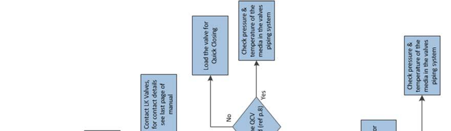
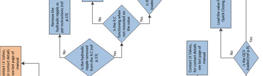
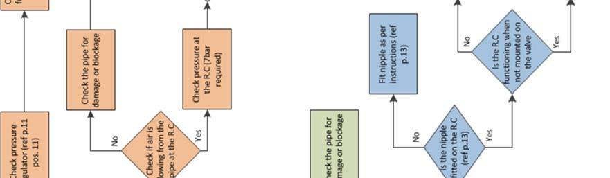
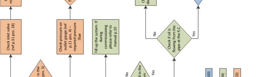
22 19. Troubleshooting scheme Article no: Revision: 8 22 (23)
23 19. Repair kit Repair kits for the pressure regulator with filter are available. Repair kit Art. No. Description Set of seals and filter element 20. Contact info Your Pneumatic Control Station is designed and manufactured by: LK Valves AB Garnisonsgatan 19 SE Helsingborg SWEDEN Telephone: +46 (0) Fax: +46 (0) Website: Article no: Revision: 8 23 (23)
FILTER REGULATORS MODEL NO: CAT155 & CAT156 FITTING & MAINTENANCE INSTRUCTIONS PART NO: & ORIGINAL INSTRUCTIONS
 FILTER REGULATORS MODEL NO: CAT155 & CAT156 PART NO: 3120169 & 3120170 FITTING & MAINTENANCE INSTRUCTIONS ORIGINAL INSTRUCTIONS GC0117 INTRODUCTION Thank you for purchasing this CLARKE Filter/Regulator.
Operating instruction
 Operating instruction MV, XV, HG, HP, RKO, D2G, TV, BV, WB & SLV 1 Introduction 2 2 Stafsjö s knife gate valves 2 3 Technical information 2 3.1 Pressure test 2 3.2 Labelling 2 4 Storage 3 5 Transportation
Installation Operation Maintenance. Bermad Level Control Valve with Modulating Horizontal Float Pilot valve One Way Flow IOM.
 Bermad Level Control Valve with Modulating Horizontal Float Pilot valve One Way Flow Model: FP 450-80 Installation Operation Maintenance PAGE 1 OF 5 1. Safety First BERMAD believes that the safety of personnel
Operating and maintenance manual Filter and reducing station Series / 1.0
 Operating and maintenance manual Filter and reducing station Series 961 04.2017 / 1.0 Original instructions ARCA Regler GmbH. All rights reserved. Cover picture background: Freepik.com ARCA Regler GmbH
LRS(H)4 USER MANUAL. Read the complete manual before installing and using the regulator.
4 USER MANUAL. Read the complete manual before installing and using the regulator.") LRS(H)4 USER MANUAL Read the complete manual before installing and using the regulator. WARNING INCORRECT OR IMPROPER USE OF THIS PRODUCT CAN CAUSE SERIOUS PERSONAL INJURY AND PROPERTY DAMAGE. Due to the
LRS(H)4 USER MANUAL Read the complete manual before installing and using the regulator. WARNING INCORRECT OR IMPROPER USE OF THIS PRODUCT CAN CAUSE SERIOUS PERSONAL INJURY AND PROPERTY DAMAGE. Due to the
Float Operated Level Controllers
 CONTENTS Float Operated Level Controllers IM0015 Nov. 2014 PAGE Introduction 1 Scope 1 Description 1 Specification 1 Control Installation 2 INTRODUCTION Side Mount Back Mount Prior to installing, the instructions
INSTALLATION INSTRUCTIONS. CVS 67CFR Pressure Reducing Instrument Supply Regulator INTRODUCTION
 INSTALLATION INSTRUCTIONS CVS 67CFR Pressure Reducing Instrument Supply Regulator INTRODUCTION The CVS Controls 67CFR Filter regulator is a pressure reducing supply regulator typically used for pneumatic
KTM OM-2 SPLIT BODY FLOATING BALL VALVES INSTALLATION AND MAINTENANCE INSTRUCTIONS
 Before installation these instructions must be fully read and understood SECTION 1 - STORAGE 1.1 Preparation and preservation for storage All valves should be properly packed in order to protect the parts
Manual Actuated Boiler Blowdown Valves
 Manual Actuated Boiler Blowdown Valves Installation and Maintenance Instructions 1. Safety information 2. General product information 3. Installation 4. Operation 5. Maintenance 6. Spare parts p.1 1. Safety
Standard Operating and Maintenance Instructions for Pumping System Model PS-90
 Standard Operating and Maintenance Instructions for Pumping System Model PS-90 High Pressure Equipment Company 2955 West 17th Street, Suite 6 PO Box 8248 Erie, PA 16505 USA 814-838-2028 (phone) 814-838-6075
SPECIFICATIONS Type: Twin stack, single phase Tank: 4 gallon Air Output: PSI; PSI Max PSI: 125 PSI HP: 1.
 2 GALLON TWIN STACK AIR COMPRESSOR Model: 9526 DO NOT RETURN TO STORE. Please CALL 800-348-5004 for parts and service. CALIFORNIA PROPOSITION 65 WARNING: You can create dust when you cut, sand, drill or
RS(H)10,15 USER MANUAL. Read the complete manual before installing and using the regulator.
10,15 USER MANUAL. Read the complete manual before installing and using the regulator.") RS(H)10,15 USER MANUAL Read the complete manual before installing and using the regulator. WARNING INCORRECT OR IMPROPER USE OF THIS PRODUCT CAN CAUSE SERIOUS PERSONAL INJURY AND PROPERTY DAMAGE. Due to
RS(H)10,15 USER MANUAL Read the complete manual before installing and using the regulator. WARNING INCORRECT OR IMPROPER USE OF THIS PRODUCT CAN CAUSE SERIOUS PERSONAL INJURY AND PROPERTY DAMAGE. Due to
Installation & Operation Manual Proven Quality since 1892
 Content 1. ERIKS operating companies 2. Product description 3. Requirements for maintenance staff 4. Transport and storage 5. Function 6. Application 7. Installation 8. Maintenance 9. Service and repair
Mounting and Operating Instructions EB 8546 EN. Type 4708 Supply Pressure Regulators. Translation of original instructions. Type Type
 Type 4708 Supply Pressure Regulators Translation of original instructions Type 4708-53 Type 4708-64 Type 4708-12 Mounting and Operating Instructions Edition March 2018 Note on these mounting and operating
PRS(TC)4,8 USER MANUAL. Read the complete manual before installing and using the regulator.
4,8 USER MANUAL. Read the complete manual before installing and using the regulator.") PRS(TC)4,8 USER MANUAL Read the complete manual before installing and using the regulator. WARNING INCORRECT OR IMPROPER USE OF THIS PRODUCT CAN CAUSE SERIOUS PERSONAL INJURY AND PROPERTY DAMAGE. Due to
PRS(TC)4,8 USER MANUAL Read the complete manual before installing and using the regulator. WARNING INCORRECT OR IMPROPER USE OF THIS PRODUCT CAN CAUSE SERIOUS PERSONAL INJURY AND PROPERTY DAMAGE. Due to
30T A/Manual Hydraulic Shop Press
 30T A/Manual Hydraulic Shop Press Operation Manual 1 1. Important Information 1.1 Safety Information 1.1.1 Hazard Symbols Used in the Manuals This manual includes the hazard symbols defined below when
Mounting and Operating Instructions EB 8546 EN. Supply Pressure Regulator Type Fig. 1 Supply pressure regulators
 Supply Pressure Regulator Type 4708 Type 4708-5352 on Type 3730 Positioner Type 4708-52 with filter receptacle Type 4708-6252 on Type 3372 ctuator Fig. Supply pressure regulators Mounting and Operating
Discontinued. Powers Controls. Technical Instructions Document No P25 RV Rev. 1, May, RV 201 Pressure Reducing Valves.
 Powers Controls RV 201 Pressure Reducing Valves Description Features Product Numbers Dual Pressure PRV Technical Instructions Document No. 155-049P25 RV 201-1 Single Pressure PRV The RV 201 Pressure Reducing
OPERATION MANUAL NTF-15
 OPERATION MANUAL NTF-15 Nitrogen Tire Filling Valve Stem Caps (Qty=200) Order P/N 436075 RTI Technologies, Inc 10 Innovation Drive York, PA 17402 800-468-2321 www.rtitech.com 035-81235-00 (Rev B) TABLE
Mounting and Operating Instructions EB EN. Type Supply Pressure Regulator. with increased air capacity
 Type 4708-45 Supply Pressure Regulator with increased air capacity Translation of original instructions Mounting and Operating Instructions EB 8546-1 EN Edition March 2016 Note on these mounting and operating
FOR INSTALLING CO 2 BLENDER KIT (P/N IN BEER SYSTEM
 IMI CORNELIUS INC One Cornelius Place Anoka, MN 55303-623 Telephone (800) 238-3600 Facsimile (612) 22-326 INSTALLATION INSTRUCTIONS FOR INSTALLING CO 2 BLENDER KIT (P/N 111612000 IN BEER SYSTEM SECONDARY
Standard Operating and Maintenance Instructions for Pumping System Model PS-150
 Standard Operating and Maintenance Instructions for Pumping System Model PS-150 High Pressure Equipment Company, LLC 2955 West 17th Street, Suite 6 PO Box 8248 Erie, PA 16505 USA 814-838-2028 (phone) 814-838-6075
WW-720. Pressure Reducing Control Valve
 WW-720 Pressure Reducing Control Valve (Size Ranges: 2-4 and 6-14 ) Installation Operation & Maintenance Page 1 of 6 1. DESCRIPTION The Model 720 Pressure Reducing is an automatic control valve (powered
Instructions for High Altitude Conversion
 6304 38 0/ US/CA For heating engineers Instructions for High Altitude Conversion Logano G334 X gas-fired boiler This conversion kit and the accompanying instructions are for conversion of G334 X gas-fired
Operation Manual Piston Sensed Gas Pressure Regulators
 687 Technology Way Napa, CA 94558 Phone: (707) 259-0102 FAX: (707) 259-0117 www.aptech-online.com Operation Manual Piston Sensed Gas Pressure Regulators (Models KT9, KT10, Welded KT10, KT12) Table of Contents:
THE BP-301 SERIES. Operating and Service Manual. Series includes all variants of BP-301 (LF 0.1Cv / MF 0.5Cv)
") THE BP-301 SERIES Operating and Service Manual Series includes all variants of BP-301 (LF 0.1Cv / MF 0.5Cv) Issue B October 2015 1 TABLE OF CONTENTS 1. Description... 3 2. Installation... 3 3. Operation...
THE BP-301 SERIES Operating and Service Manual Series includes all variants of BP-301 (LF 0.1Cv / MF 0.5Cv) Issue B October 2015 1 TABLE OF CONTENTS 1. Description... 3 2. Installation... 3 3. Operation...
OPERATION MANUAL NTF-60 Plus
 OPERATION MANUAL NTF-60 Plus Nitrogen Tire Filling Valve Stem Caps (Qty=200) Order P/N 436075 RTI Technologies, Inc 10 Innovation Drive York, PA 17402 800-468-2321 www.rtitech.com 035-81264-00 (Rev A)
Differential Pressure Regulator Type Type 45-6 (0.1 to 1 bar, DN 15) Mounting and Operating Instructions EB 3226 EN
 Mounting and Operating Instructions EB 3226 EN") Differential Pressure Regulator Type 45-6 Type 45-6 (0.1 to 1 bar, DN 15) Mounting and Operating Instructions EB 3226 EN Edition March 2008 Contents Contents Page 1 Design and principle of operation...................
Differential Pressure Regulator Type 45-6 Type 45-6 (0.1 to 1 bar, DN 15) Mounting and Operating Instructions EB 3226 EN Edition March 2008 Contents Contents Page 1 Design and principle of operation...................
Operating Manual. R280 Pressure regulator made of brass. 1. Intended Use
 Pressure regulator made of brass Operating Manual 1. Intended Use Line or outlet pressure regulators- /reducer for Air, gases and liquids which is designed to effect reduction to a downstream pressure
Budget Range Operators Handbook
 Budget Range Operators Handbook BAMBI AIR COMPRESSORS LTD 152 Thimble Mill Lane Heartlands Birmingham B7 5HT United Kingdom Tel: 0121 322 2299 Fax: 0121 322 2297 Email: sales@bambi-air.co.uk www.bambi-air.co.uk
BR 27g. Operating, assembly and maintenance instructions for discontinuous sampling valve. 1. Design, operation and dimensions:
 Operating, assembly and maintenance instructions for discontinuous sampling valve BR 27g The equipment may only be dismounted and disasembled by skilled staff, who are familiar with the assembly, start-up,
Bray/ VAAS O-Ported Series Knife Gate Valve 770/780 Series Operation and Maintenance Manual
 Bray/ VAAS Knife Gate Valve 770/780 Series Operations and Maintenance Manual Table of Contents Definition of Terms 1 Safety Instructions 1 Introduction 2 Unpacking 2 Storage 2 Installation 2 Commissioning
WW-730. Pressure Sustaining/Relief Control Valve
 WW-730 Pressure Sustaining/Relief Control Valve Installation Operation & Maintenance Page 1 of 6 1. DESCRIPTION The Model 730 Pressure Relief / Sustaining Valve is an automatic control valve designed to
Neotecha SAPRO - Aseptic sampling valve SV Installation, operation and maintenance instructions
 Before installation these instructions must be fully read and understood 2 Safety Please read these instructions carefully. 2.1 General danger potential Not paying attention to this instruction Incautious
Code AWC20HP Air Compressor
 Code 951816 AWC20HP Air Compressor Index of Contents Index of Contents 02 Declaration of Conformity 02 What s Included 03 Safety Precautions 03 Specifications (AWC20HP Air Compressor) 04 Assembly Instructions
Operation Manual Air Saver Unit ASV5000 Series
 9IM-V066-b Operation Manual Air Saver Unit ASV5000 Series Thank you for your choice of Kuroda Pneumatics LTDs product on this time. Please read this operation manual carefully and use the product correctly.
Mounting and Operating Instructions EB 3007 EN. Self-operated Pressure Regulators. Differential Pressure Regulators (opening) Type Type 42-25
 Type Type 42-25") Self-operated Pressure Regulators Differential Pressure Regulators (opening) Type 42-20 Type 42-25 Type 42-20 Differential Pressure Regulator Type 42-25 Differential Pressure Regulator Mounting and Operating
Self-operated Pressure Regulators Differential Pressure Regulators (opening) Type 42-20 Type 42-25 Type 42-20 Differential Pressure Regulator Type 42-25 Differential Pressure Regulator Mounting and Operating
User Instruction Manual
 User Instruction Manual 4500 psi Air Compressor Ver 2, 1.18 Contents Parts Included...3 Assembly Instructions...3-5 Operation Instructions...6-7 Oil Change Intervals...8 Air Filter Replacement...9 Setting
Pressure Dump Valve Service Kit for Series 2300 Units
 Instruction Sheet Pressure Dump Valve Service Kit for Series 00 Units. Overview The Nordson pressure dump valve is used to relieve hydraulic pressure instantly in Series 00 applicator tanks when the unit
THE MF-400 SERIES. Operating and Service Manual. Series includes all variants of MF-400/401
 THE MF-400 SERIES Operating and Service Manual Series includes all variants of MF-400/401 Issue A October 2013 1 TABLE OF CONTENTS 1. Description... 3 2. Installation... 3 3. Operation... 4 4. Special
Propane Conversion Kit Instructions
 604 8 0/ US/CA For heating engineers Propane Conversion Kit Instructions Logano G4 X gas-fired boiler This conversion kit and the accompanying instructions are for conversion of G4 X gas-fired boilers
2 GALLON TWIN STACK AIR COMPRESSOR W/ HOSE REEL
 2 GALLON TWIN STACK AIR COMPRESSOR W/ HOSE REEL Model: 52024 CALIFORNIA PROPOSITION 65 WARNING: You can create dust when you cut, sand, drill or grind materials such as wood, paint, metal, concrete, cement,
WW-720. Pressure Reducing Control Valve
 WW-720 Pressure Reducing Control Valve (Size Ranges: 2-4 and 6-14 ) Installation Operation & Maintenance Page 1 of 6 1. DESCRIPTION The Model 720 Pressure Reducing is an automatic control valve (powered
Instruction Manual. Alfa Laval SB Membrane Sample Valve ESE02963-EN Original manual
 Instruction Manual Alfa Laval SB Membrane Sample Valve ESE02963-EN2 2016-02 Original manual Table of contents The information herein is correct at the time of issue but may be subject to change without
RG1200 Service and Repair Manual
 Dive Rite RG 1200 Regulator Service and Repair Manual Page 1 Text and Photography by Pete Nawrocky Copyright ( ) 1999-2000, Lamartek, Inc., dba Dive Rite RG1200 Service and Repair Manual First Stage.........................................
SILENTAIRE TECHNOLOGY
 SILENTAIRE TECHNOLOGY 8614 Veterans Memorial. Houston, Texas 77088 832/327-7452 800/972-7668 Fax: 832/327-0668 E-mail: silentaire@silentaire.com Thank you and congratulations on the purchase of your OILLESS
APCO ARV CLEAN WATER AIR RELEASE VALVES. Model 50A
 APCO ARV CLEAN WATER AIR RELEASE VALVES Model 50A Instruction D12013 February 2017 Instructions These instructions provide installation, operation and maintenance information for APCO ARV Clean Water Air
MODEL 200 KNIFE GATE VALVES INSTALLATION & MAINTENANCE MANUAL
 MODEL 200 KNIFE GATE VALVES INSTALLATION & MAINTENANCE MANUAL Index 1. List of components / General arrangement 2. Description 3. Handling 4. Installation 5. Actuators / Operation 6. Maintenance a. Changing
Spilt body Flange ball valve. TC-205MFF-PN1640 User Manual English Version. Document No: TC-205MFF-PN1640.Ur-manual. Date: 2007/04/2617. Version: 1.
 Spilt body Flange ball valve TC-205MFF-PN1640 Series PED Category I,II TC-205MFF-PN1640 User Manual English Version Use for company in Europe who will place the product on the market, please amend which
Instruction Manual. Alfa Laval SB Pressure Exhaust Valve ESE02965-EN Original manual
 Instruction Manual Alfa Laval SB Pressure Exhaust Valve ESE02965-EN1 2015-10 Original manual Table of contents The information herein is correct at the time of issue but may be subject to change without
A3S Bellows Sealed Stop Valve Installation and Maintenance Instructions
 1326050/3 IM-P132-11 ST Issue 3 A3S Bellows Sealed Stop Valve Installation and Maintenance Instructions 1 General safety information 2 General product information 3 Installation 4 Commissioning 5 Operation
OPERATING AND MAINTENANCE MANUAL
 Series 4300 Engineered Performance TABLE OF CONTENTS 0 INTRODUCTION 1 1 Scope 1 2 Description 1 3 Specifications 1 0 INSTALLATION 1 1 Mounting 1 2 Piping 1 1 Connecting Process Pressure 2 2 Vent Connections
RC 195 Receiver-Controller
 Document No. 129-082 RC 195 Receiver-Controller Product Description The POWERS RC 195 Receiver-Controller is a pneumatic instrument that receives one, two or three pneumatic inputs. It produces a pneumatic
Pressure-limiting valve and pre-load valve type MVG, MVE and MVP
 Pressure-limiting valve and pre-load valve type MVG, MVE and MVP Product documentation Directly controlled Operating pressure pmax: Flow rate Qmax: 700 bar 8 lpm D 3726 02-2016-1.3 by HAWE Hydraulik SE.
BCV31 DN40 - Blowdown Control Valve
 4034850/5 IM-P403-71 AB Issue 5 BCV31 DN40 - Blowdown Control Valve Installation and Maintenance Instructions 1. Safety information 2. Application 3. Technical data 4. Operation 5. Installation 6. Flow
THE HF-300 SERIES. Operating and Service Manual. Series includes all variants of HF-300/301
 THE HF-300 SERIES Operating and Service Manual Series includes all variants of HF-300/301 Issue A July 2015 1 TABLE OF CONTENTS 1. Description... 3 2. Installation... 3 3. Operation... 4 3.1. Spring Loaded...
LUBRICATOR ASSEMBLY AND OPERATING INSTRUCTIONS
 AIR FILTER, REGULATOR AND LUBRICATOR 4035 ASSEMBLY AND OPERATING INSTRUCTIONS 349 Mission Oaks Blvd., Camarillo, CA 930 Visit our Web site at http://www.harborfreight.com Copyright 004 by Harbor Freight
Installation, Operation and Maintenance Manual for Back Pressure Regulator
 Installation, Operation and Maintenance Manual for Back Pressure Regulator Model 8860 2009 Groth Corporation IOM-8860 Rev. B 12541 Ref. ID: 95565 Page 2 of 13 Table of Contents I. INTRODUCTION 3 II. DESIGN
Bermad Pressure Reducing. Model: 42T
 Bermad Pressure Reducing Pilot Operated Pressure Control Valve Model: 42T Installation Operation Maintenance Manual (IOM) REV. 27.7.17 Page 1 of 12 Safety First BERMAD believes that the safety of personnel
Types 749B and R130 Changeover Manifolds
 Instruction Manual MCK-1179 Types 749B and R130 June 2012 Types 749B and R130 Changeover Manifolds TYPE HSRL-749B TYPE 64SR/122 TYPE R130/21 TYPE 749B/21 Figure 1. Changeover Manifolds and Regulator Assemblies
1 DRIVE INDUSTRIAL IMPACT WRENCH
 1 DRIVE INDUSTRIAL IMPACT WRENCH 92622 ASSEMBLY AND OPERATING INSTRUCTIONS 3491 Mission Oaks Blvd., Camarillo, CA 93011 Visit our Web site at http://www.harborfreight.com Copyright 2004 by Harbor Freight
Model Secure-Gard Pilot Operated Vent Valve SECTION II. Remove all packing material inside and outside of the valve prior to installation.
 INSTALLATION, OPERATION AND MAINTENANCE MANUAL (IOM) IOM - 1049 01-17 Model 1049 Secure-Gard Pilot Operated Vent Valve ISO Registered Company SECTION I I. DESCRIPTION AND SCOPE The Model 1049 Secure-Gard
MEGR-1912 Instruction Manual
 MEGR-1912 PRESSURE REGULATOR Instruction Manual- Look Inside For: Description Installation Start-Up Maintenance Parts Ordering Parts List Marshall Excelsior Company Marshall, MI 49068 269-789-6700 FAX
Pfeiffer. Operating, assembly and maintenance instructions for discontinuous sampling valve Series 27i. 1. Design, operation and dimensions
 Operating, assembly and maintenance instructions for discontinuous sampling valve Series 27i This equipment may only be dismounted and disassembled by skilled staff, who are familiar with the assembly,
Related Products: Auto Drain Valve. Model/Specifications. Model
 Related Products: Auto Drain Valve /600 Drainage is automatically discharged in a reliable manner, without requiring human operators. Highly resistant to dust and corrosion, operates reliably, and a bowl
Needle valve. Contents. User s Manual. (1) Be sure to read the following warranty clauses of our product 1. (2) General operating instructions 2
 Be sure to read the following warranty clauses of our product 1. (2) General operating instructions 2") Serial No. H-V024-E-7 Needle valve User s Manual Contents (1) Be sure to read the following warranty clauses of our product 1 (2) General operating instructions 2 (3) General instructions for transportation,
Serial No. H-V024-E-7 Needle valve User s Manual Contents (1) Be sure to read the following warranty clauses of our product 1 (2) General operating instructions 2 (3) General instructions for transportation,
1200B2 Series Service Regulators. Instruction Manual
 00B Series Service Regulators Instruction Manual 00B Series Service Regulators 0 Elster American Meter 00B Series Service Regulators General Information The 00B Series Service Regulators are available
RS(H)20, 25 USER MANUAL
20, 25 USER MANUAL") RS(H)20, 25 USER MANUAL Read the complete manual before installing and using the regulator. WARNING Before removing a regulator from the system for service, you must depressurize system purge the system
RS(H)20, 25 USER MANUAL Read the complete manual before installing and using the regulator. WARNING Before removing a regulator from the system for service, you must depressurize system purge the system
SILENTAIRE TECHNOLOGY
 SILENTAIRE TECHNOLOGY General User and Maintenance Instructions Thank you and congratulations on the purchase of your PANTHER, the leader in the industry of portable air compressors. The PANTHER is built
SC6H OIL-LESS AIR COMPRESSOR
 SC6H OIL-LESS AIR COMPRESSOR OWNER S MANUAL FOR YOUR SAFETY PLEASE READ THESE INSTRUCTIONS CAREFULLY AND RETAIN THEM FOR FUTURE USE. MAIN COMPONENTS 1. ON/OFF switch 2. Outlet valve 3. Regulating valve
Assembly-, installation- and maintenance instruction manual for bladder accumulators IBV / EBV , top reparable
 Page 1 von 8 Assembly-, installation- and maintenance instruction manual for bladder accumulators IBV / EBV 100-575, top reparable Content Seite 0 Legend 2 1 Overview 2 2 Accumulator assembly and installation
abc OPERATING, INSTALLATION & MAINTENANCE MANUAL FOR G6 GAS SAMPLER
 OPERATING, INSTALLATION & MAINTENANCE MANUAL FOR G6 GAS SAMPLER This Jiskoot Product is designed to provide outstanding service if correctly installed, used and maintained recognising the effects of the
Components for air preparation and pressure adjustment. OUT port position ( ) connected Rear side. of IN port. Air tank. directly.
 connected Rear side. of IN port. Air tank. directly.") Components preparation and pressure adjustment ABP Overview ABP is a component that enables boosting by s only up to twice primary pressure (.0MPa max.) in combination with using air tank but not using
Components preparation and pressure adjustment ABP Overview ABP is a component that enables boosting by s only up to twice primary pressure (.0MPa max.) in combination with using air tank but not using
Operation Manual. Diaphragm Sensed Gas Pressure Regulators
 687 Technology Way Napa, CA 94558 Phone: (707) 259-0102 FAX: (707) 259-0117 www.aptech-online.com Diaphragm Sensed Gas (AP/AZ/AK Models: 20, 100, 500, 1000, 1000T 10PA, 1100, 1200, 12PA, 1300, 1400T, 14PA,
Type 3709 Pneumatic Lock-up Valve. Translation of original instructions. Mounting and Operating Instructions EB 8391 EN
 Type 3709 Pneumatic Lock-up Valve Translation of original instructions Mounting and Operating Instructions EB 8391 EN Edition July 2017 Note on these mounting and operating instructions These mounting
Model GP PRESSURE REDUCING VALVE Installation & Operation Manual
 Model GP-2000 PRESSURE REDUCING VALVE Installation & Operation Manual Please read this bulletin thoroughly before using the pressure reducing valve, so that you may do so correctly and safely. Please carefully
TECHNICAL DATA MAINTENANCE AIR COMPRESSOR MODEL G-1
 Dry 131h 1. DESCRIPTION The Viking Model G-1 Maintenance Air Compressor is an electric motor-driven, aircooled, single-stage, oil-less compressor. The unit is equipped with a check valve and provides a
N2 Blanketing Valve DST100 / DST200 TYPE INSTRUCTION MANUAL CONTENTS K.S.P.C. General Description Operation. Installation Maintenance
 DST100 / DST200 TYPE N2 Blanketing Valve INSTRUCTION MANUAL CONTENTS General Description Operation Installation Maintenance K.S.P.C 488-1 Wolha-ro, Tongjin-eup, Gimpo-si, Gyeonggi-Do, Korea Tel : +82-31-998-3825~7
Installation, Operation, Maintenance Manual For Quick-Jaw Models AL363, L364 & AL366
 Installation, Operation, Maintenance Manual For Quick-Jaw Models AL363, L364 & AL366 February 2014 Form FVC076 - Rev 07 IMPORTANT: KEEP THIS DOCUMENT WITH THE PRODUCT UNTIL IT REACHES THE END USER. 1.
AMP Oil Free Manual AMP 50-8-TC AMP 50-6-D AMP General User and Maintenance Instructions
 AMP Oil Free Manual AMP 50-8-TC AMP 50-6-D AMP 50-24 General User and Maintenance Instructions Silentaire Technology 8614 Veterans Memorial Dr. Houston, TX 77088 800-972-7668 Fax 832-327-0669 www.silentaire.com
Pressure Differential Automatic Manifold For LPG. PDH1000 Series. LPG Installation & Operations Instructions
 Pressure Differential Automatic Manifold For LPG PDH1000 Series LPG Installation & Operations Instructions Precise Equipment Company 3822 Market St., STE 101 Denton, Texas Phone : 800.795.8388 Precise
1. Preface Important Safety Notes Brief Product Information Product Working Principle Installation Guidelines...
 Table of Contents 1. Preface...1 2. Important Safety Notes...1 3. Brief Product Information...3 4. Product Working Principle...5 5. Installation Guidelines...6 6. Startup and Commissioning...8 7. Maintenance
CARTRIDGE FILTERS TECHNICAL MANUAL MT 080. Installation, commissioning and maintenance instructions. 08/02 Edition
 CARTRIDGE FILTERS TECHNICAL MANUAL MT 080 Installation, commissioning and maintenance instructions 08/02 Edition 1 2 CONTENTS 1.0 PAGE INTRODUCTION 1.1 MAIN FEATURES 1.2 OPERATION 1.3 CLOSING OF HEAD WITH
OPERATING INSTRUCTIONS
 0/05 OPERATING INSTRUCTIONS for gas pressure regulators PN0 with integrated slam shut valve (SSV) and integrated limited capacity safety relief valve (RV) MR 25 F0, MR 25 SF0 p e 20 kpa - 0 MPa (0,2-0
OPERATING MANUAL. Contents. Bottom outlet ball valve Type ecoline
 OPERATING MANUAL Bottom outlet ball valve Type ecoline Contents 1 General Information 2 Safety 3 Packing, Handling, Storing 4 Product description 5 Preparation, Assembly 6 Commissioning 7 Handling 8 Attendance
THE BP-690 SERIES. Operating and Service Manual. Series includes all variants of BP-LF/MF-690/691
 THE BP-690 SERIES Operating and Service Manual Series includes all variants of BP-LF/MF-690/691 Issue B April 2015 1 TABLE OF CONTENTS 1. Description... 3 2. Installation... 3 3. Operation... 4 4. Special
DelVal Flow Controls Private limited
 DelVal Flow Controls Private limited (A DIVISION OF DelTech CONTROLS LLC, USA) DelVal Series 50/5, 5A/5B Butterfly Valves INSTALLATION, OPERATION AND MAINTENANCE MANUAL ENGINEERING DATA SHEET E.D.S. NO
ATS430 turbidity sensor Retractable insertion assembly
 A MEASUREMENT & ANALYTICS INSTRUCTION ATS430 turbidity sensor Retractable insertion assembly Measurement made easy 1 Introduction This publication details installation procedures for the retractable insertion
RARS5000 AIR BODY SAW OWNER S OPERATING MANUAL
 RARS5000 AIR BODY SAW OWNER S OPERATING MANUAL DESCRIPTION 1. No mar 2. No mar tip 3. Housing grip 4. Trigger 5. Air inlet 6. Air inlet plug 7. Plastic board Important! It is essential that you read the
BCV31 DN20 - Blowdown Control Valve
 4034650/8 IM-P403-37 AB Issue 8 BCV31 DN20 - Blowdown Control Valve Installation and Maintenance Instructions 1. Safety information 2. Application 3. Technical data 4. Operation 5. Installation 6. Flow
LRS(H)4 Pressure-Reducing Regulator User Manual
4 Pressure-Reducing Regulator User Manual") LRS(H)4 Pressure-Reducing Regulator User Manual Read the complete manual before installing and using the regulator. 2 Safe Product Selection When selecting a product, the total system design must be considered
LRS(H)4 Pressure-Reducing Regulator User Manual Read the complete manual before installing and using the regulator. 2 Safe Product Selection When selecting a product, the total system design must be considered
Index Table. Model 794. Installation, Operating and Maintenance Instructions
 CLOCKWISE MANUAL MAKING INTO CCW TABLE Index Table Model 794 Installation, Operating and Maintenance Instructions Black & Webster Products Division 545 Hupp Ave. P.O. Box 831, Jackson, Michigan 49204 2009
Two-stage valve type NE
 Two-stage valve type NE Product documentation Operating pressure pmax: Flow rate Qmax: 700 bar (High pressure) 80 bar (Low pressure) 25 lpm (High pressure) 180 lpm (Low pressure) D 7161 03-2017-1.0 by
Propane Conversion Kit Instruction
 Propane Conversion Kit Instruction Condensing gas boiler Required Input Rates GB142-24 84,800 btu/hr GB142-30 106,000 btu/hr GB142-45 160,900 btu/hr GB142-60 214,800 btu/hr This kit and instructions are
TESCOM 50-4X Series Safety, Installation & Start-Up Procedures
 Operations & Service Manual TESCOM 50-4X Series Safety, Installation & Start-Up Procedures Do not attempt to select, install, use or maintain this product until you have read and fully understood this
AIR HAMMERS MODEL NO: CAT138/CAT139 OPERATING & MAINTENANCE INSTRUCTIONS PART NO: / GC064
 AIR HAMMERS MODEL NO: CAT138/CAT139 PART NO: 3120152 /3120153 OPERATING & MAINTENANCE INSTRUCTIONS GC064 INTRODUCTION Thank you for purchasing this CLARKE Air Hammer. Before attempting to use this product,
Type S301 & S302 Gas Regulators INTRODUCTION INSTALLATION. Scope of Manual. Description. Specifications. Type S301 and S302. Instruction Manual
 Fisher Controls Instruction Manual Type S301 & S302 Gas Regulators October 1981 Form 5180 WARNING Fisher regulators must be installed, operated, and maintained in accordance with federal, state, and local
Propane Conversion Kit Instruction
 Propane Conversion Kit Instruction Condensing gas boiler Required Input Rates Logamax plus GB62-80 kw 270,000 btu/hr Logamax plus GB62-00 kw 35,000 btu/hr This kit and instructions are for converting the
24L AIR COMPRESSOR MODEL NO: TIGER 11/250 PART NO: OPERATION & MAINTENANCE INSTRUCTIONS LS01/13
 24L AIR COMPRESSOR MODEL NO: TIGER 11/250 PART NO: 2244010 OPERATION & MAINTENANCE INSTRUCTIONS LS01/13 INTRODUCTION Thank you for purchasing this product. Before attempting to use this product, please
Type Pressure Regulator. for increased air capacity. Fig. 1: Type Pressure Regulator. Mounting and Operating Instructions EB EN
 Type 4708-45 Pressure Regulator for increased air capacity Fig. 1: Type 4708-45 Pressure Regulator Mounting and Operating Instructions EB 8546-1 EN Edition March 2010 Definition of the signal words used