1.0 - OPENING AND CLOSING THE DOOR
|
|
|
- Carmel Mosley
- 6 years ago
- Views:
Transcription

1

 on vessel to which the closure is attached should remain in open position while opening and closing the door.")


 need replaced [fig 2]. 1.")
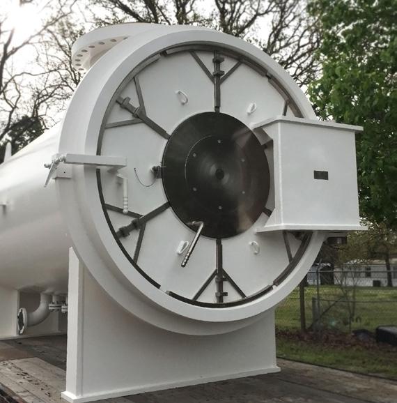
2 The purpose of this manual is to provide the user with instructions on how to safely open and close, how to conduct routine maintenance, and how to install the PEI TWINLOCK Closure on a pressure vessel. Please follow these instructions, observe all safety and warning notices. Consult factory should you have any questions or concerns OPENING AND CLOSING THE DOOR Do not attempt to open the door until all internal vessel pressure is released. The vent valve(s) on vessel to which the closure is attached should remain in open position while opening and closing the door. A pressure gage should be located on the vessel to confirm there is no internal pressure. During the opening of the door, the operator should stand to the side, opposite the hinge arm [fig 1]. When opening and closing door the operator should be properly equipped with personal protective equipment. The opening and closing of the TWINLOCK Closure does not require the use of tools. Tools used to force the door open or closed or to tighten the pressure alert valve may cause permanent damage to the closure. Spare O-rings should always be readily available during the opening/closing operations should the operator find the O-Ring(s) need replaced [fig 2] OPENING THE DOOR Step 1: With the internal pressure completely released using the vent valve(s) located on the vessel and with a pressure gage confirming the internal pressure is (0) PSI, manually unscrew the Pressure Alert Valve [fig 3] in counter clockwise direction. Once the Pressure Alert Valve seal is broken, should a pressure release be detected, retighten and determine the cause of this pressure release before continuing. Should internal pressure not be detected, continue to unthread the Pressure Alert Valve until it is completely free, allowing it to hang from the attachment cable [fig 4]. 1


![lugs [fig 7].](/docs-images/74/71424219/images/3-3.jpg "Step 4: With door locking lugs disengaged, use door handle to open the")
3 Step 2: With the Pressure Alert Valve completely removed, lift and hold the Safety Lock [fig 5] in upward position. Step 3: Standing to the side opposite the door hinge, with Safety Lock in upward position, rotate door handle [fig 6] to disengage the door locking lugs [fig 7]. Step 4: With door locking lugs disengaged, use door handle to open the door [fig 8], and swing door to open position [fig 9] to gain internal access to vessel. 2

![Step 2: With the door completely closed, lift door handle to fully engage the door locking lugs [fig 11].](/docs-images/74/71424219/images/4-1.jpg "If the locking lugs are not easily moved into lock position, do not force handle upward.")


4 1.2 - CLOSING THE DOOR Refer to closure Maintenance Section to assure certain maintenance items are conducted before closing door. Step 1: With door in open position, use door handle to close the door [fig 10]. Step 2: With the door completely closed, lift door handle to fully engage the door locking lugs [fig 11]. If the locking lugs are not easily moved into lock position, do not force handle upward. This is an indication the door may not be completely closed or properly aligned. Check to determine problem before continuing. Step 3: With locking lugs engaged, and door handle moved to lock position, the Safety Lock should fall into the full lock position [fig 12], allowing the Pressure Alert Valve to be easily installed. Note: it may be necessary to manually push the Safety Lock into to the lock position if this mechanism is not properly maintained and lubricated. There is a weather seal located behind the slidelock. This protects the latching mechanism from debris. Step 4: With Safety Lock in locked position, re-install the Pressure Alert Valve by hand tightening only [fig 13]. The vessel to which the closure is attached can now be pressurized. 3
.")

![) O-Rings: The closure is equipped with two pressure containment O-Rings. One O-Ring located on the Pressure Alert Valve [fig 15].](/docs-images/74/71424219/images/5-2.jpg "Another O-Ring is located on the outer periphery of the door [fig 16].")


5 2.0 - MAINTENANCE INSTRUCTIONS The TWINLOCK Closure (if properly maintained) will provide many years of service. Surfaces Protection All non-painted, non-plated surfaces should be protected with a thin coating of grease [fig 14] (Recommended: Mobil XHP222). Factory recommends that plated surfaces should not be painted. All painted surfaces should be maintained properly. (NOTE: TWINLOCK Closures are shipped with primer only unless otherwise specified.) O-Rings: The closure is equipped with two pressure containment O-Rings. One O-Ring located on the Pressure Alert Valve [fig 15]. Another O-Ring is located on the outer periphery of the door [fig 16]. The O-Rings as shipped from the factory are normally Viton material, unless otherwise specified upon order placement, or if changed during their service life. It is important the O-Ring material be compatible with the pipeline product. Often when O-Rings are not compatible they may swell. This may make it difficult to close the door. We recommend that each time the door is opened that spare O-Rings should be readily available should the operator find it necessary to replace. The O-Rings should be removed and inspected each time the door is opened [fig 17]. The O-Ring grooves should also be inspected and cleaned, with a thin film of grease applied to the groove and O-Ring [fig 18] (Recommended: Mobil XHP222). Replacement O-Rings are readily available from factory. 4
 Door Alignment: The closure door must be kept in proper alignment to ease the opening and closing operation.")


![Step 1: Remove the protective adjustment caps at the top and bottom of the hinge arm [fig 19].](/docs-images/74/71424219/images/6-3.jpg "Step 2: With the door open, remove the primary O-Ring on the outer periphery of the door [fig 20].")
6 2.0 - MAINTENANCE INSTRUCTIONS (CONT.) Door Alignment: The closure door must be kept in proper alignment to ease the opening and closing operation. Should the door become misaligned, it can be realigned by performing the following steps: Do not attempt to open the door until all internal vessel pressure is released. The pressure release valve on vessel to which the closure is attached should remain in open position while opening and closing the door. A pressure gage should be located on the vessel to confirm there is no internal pressure. Step 1: Remove the protective adjustment caps at the top and bottom of the hinge arm [fig 19]. Step 2: With the door open, remove the primary O-Ring on the outer periphery of the door [fig 20]. Step 3: With O-Ring removed, close the door, do not engage locking lugs. The gap between the outer periphery of the door and inner periphery of the hub can now be viewed and accessed [fig 21]. 5

![Step 5: If gap is inconsistent, using an allen wrench, slightly loosen the four(4) set screws at the top [fig 24] and bottom [fig 25] of](/docs-images/74/71424219/images/7-1.jpg "the hinge arm.")


![Step 7: Lubricate and replace the Door O-Ring [fig 26], and protective caps [fig 27]. Lubricate the hinge using the grease zerk [fig 28].](/docs-images/74/71424219/images/7-4.jpg "NOTE: During the adjustment process there four set screws at the top and four sets screws at the bottom of hinge arm.")

7 2.0 - MAINTENANCE INSTRUCTIONS (CONT.) Step 4: Pass a feeler gauge along the entire circumference of the door. The recommended gap is [fig 22 & 23]. Step 5: If gap is inconsistent, using an allen wrench, slightly loosen the four(4) set screws at the top [fig 24] and bottom [fig 25] of the hinge arm. Continue adjusting inner and outer set screws until a uniform gap is achieved around the entire periphery of the closure door. If the locking lugs are not easily moved into lock position DO NOT FORCE HANDLE. It may be necessary to adjust front and rear set screws to ensure door is seated flat with the hub. Step 6: Make sure all set screws are tight, open and close the door several times to assure there is not door drag on the closure hub. Step 7: Lubricate and replace the Door O-Ring [fig 26], and protective caps [fig 27]. Lubricate the hinge using the grease zerk [fig 28]. NOTE: During the adjustment process there four set screws at the top and four sets screws at the bottom of hinge arm. The door may be tilted left or right and/or moved left or right by using inner and outer adjustments. The door may be tilted in or out and/or moved in or out using near and far adjustments. NOTE: Each Protective cap is equipped with an O-Ring located on the outer face of the cap. This is a non-pressure containing O-Ring and used as weather seal protecting the hinge arm bearings. Replace as necessary throughout the life of the closure [fig 29]. The vessel to which the closure is attached may be placed in service after the door is completely closed, the latch mechanism fully engaged, and the Pressure Alert Valve installed. 6

8 3.0 - WELDING INSTRUCTIONS The TWINLOCK Quick Opening Closure is a highly precision machined product and must be handled and welded correctly to avoid damage during installation. The closure hub is weld beveled for weld attachment to pipe or pressure vessel [fig 30]. MTR s (material test reports) are furnished with each closure which identifies the material and material grade of the weld hub. It is the responsibility of the installer to determine the appropriate weld procedure and weld code for installing the closure. 1 THE FOLLOWING ARE GENERAL RECOMMENDATIONS FOR WELD INSTALLING THE TWINLOCK. Step 1: Position the closure in correct alignment with the pipe or vessel. Tack weld per applicable code assuring the door hinge arm is in true vertical position. 3 2 Step 2: With the door oriented in the correct position, open the door and remove the primary door seal O-ring located on the outer periphery of the door, then remove the smaller O-ring on the Pressure Alert Valve. 2 SEQUENCE OF WELDING 3 Step 3: Close the door and weld per applicable procedure and code. An example of a recommended weld pass sequence is pictured right [fig 31]. 1 START STOP POST WELD HEAT TREATMENT If post weld heat treatment is required, it is recommended a localized heat treatment procedure be followed. Coat O-Ring groove and surfaces with a heat resistant coating. Interior braces should be used to prevent warp or droop. After post-weld heat treatment, remove braces, open and close door to assure alignment is correct, clean and lubricate O-Ring surfaces, replace O-Rings. If localized heat treatment is not possible and entire vessel must be heat treated, the closure door and bearings may be removed by removing the adjustment screws and hinge pin. 7

![On vertical closures equipped with hydraulic lift [fig 32]: Using the hydraulic pump handle located on the davit arm, stroke pump until door is lifted and clears closure hub, then swing to left or](/docs-images/74/71424219/images/9-1.jpg "right to gain access to inside of vessel. Swing closure door centered over hub and release valve on the side of the pump slowly to close.")

9 4.0 - VERTICAL CLOSURES PEI Vertical closures are to be installed in top vertical position only. For instructions on opening and closing the door refer to Section 1.0 Do not open vertical closure doors in the horizontal position. On vertical closures equipped with hydraulic lift [fig 32]: Using the hydraulic pump handle located on the davit arm, stroke pump until door is lifted and clears closure hub, then swing to left or right to gain access to inside of vessel. Swing closure door centered over hub and release valve on the side of the pump slowly to close. Follow all maintenance instructions as stated in maintenance section. On vertical closures equipped with jackscrew lift [fig 33]: Using the hand wheel, rotate until door is lifted and clear closure hub, then swing to left or right to gain access to inside of vessel. Swing closure door centered over hub and reverse the process to close. Follow all maintenance instructions as stated in maintenance section FLANGED TWINLOCK QUICK OPENING CLOSURE The PEI Flanged TWINLOCK [fig 34] is designed and rated to be installed by bolting to a mating and matching flange. Proper studs, nuts, gaskets meeting code requirement should be used and tightened in sequence to the desired torque specifications during installation. For instructions on opening and closing the door, refer to Section 1.0. If adjustments are required refer to section


10 ITEM NO. QTY DESCRIPTION ITEM NO. QTY DESCRIPTION 1 1 HUB 13 1 SAFETY LOCK 2 1 DOOR 14 1 SLIDE PLATE V-SEAL 3 4 LUG ARM ASSEMBLY 15 1 SLIDE PLATE 4 1 DOOR O-RING 16 1 CENTER CAP 5 1 HINGE ARM ASSEMBLY 17 4 CAP SCREW 6 2 HINGE CAP 18 1 SLIDE PLATE HANDLE 7 2 HINGE ADJUSTER 19 4 LUG HOUSING ASSEMBLY 8 2 HINGE BUSHING 20 1 PRESSURE ALERT BUSHING 9 8 ADJUSTMENT SCREW 21 1 PRESSURE ALERT O-RING 10 1 HINGE PIN 22 1 PRESSURE ALERT VALVE 11 1 GREASE ZERK 23 1 WIRE ROPE LANYARD 12 2 HINGE CAP O-RING 24 2 DRIVE SCREW 9

11 SERVICE NOTES 10

12 TWINLOCK QUICK OPENING CLOSURE OPERATION, MAINTENANCE, AND INSTALLATION MANUAL (NO. 0816)
Threaded Closures Installation, Operation & Maintenance
 Howard Street Bulletin TT Louisville, KY 0 USA Revised Jan 0 Phone 0--0 Fax 0--00 Threaded Closures Installation, Operation & Maintenance Caution: Operating a closure can be a hazardous activity and certain
INSTALLATION, OPERATION AND MAINTENANCE GUIDE
 INSTALLATION, OPERATION AND Placement in Pipeline System When installing Process Development & Control s ElastoTITE Elastomer-Hinged Check Valves in a pipeline, a minimum of five pipe diameters should
SALCO PRODUCTS, INC. PRESSURE RELIEF VALVE STORAGE, INSTALLATION, OPERATING, MAINTENANCE/TESTING, AND INSPECTION INSTRUCTIONS
 STORAGE INSTRUCTIONS Until it is time to install a new or reconditioned valve on the car, the valve must be kept in its original packaging in order to protect it from dirt and damage. INSTALLATION INSTRUCTIONS
DelVal Flow Controls Private limited
 DelVal Flow Controls Private limited (A DIVISION OF DelTech CONTROLS LLC, USA) DelVal Series 50/5, 5A/5B Butterfly Valves INSTALLATION, OPERATION AND MAINTENANCE MANUAL ENGINEERING DATA SHEET E.D.S. NO
GREIG FILTERS, INC. OPERATION MANUAL
 GREIG FILTERS, INC. OPERATION MANUAL MODEL DCFH 3P 15/3 100 S4 DOE/222 DUAL CARTRIDGE FILTER HOUSING TABLE OF CONTENTS I. INTRODUCTION II. CARTRIDGE FILTER HOUSING UNIT A. OPERATION B. INSTALLATION C.
Engineering Data Sheet
 Page 1 of 6 CE MARKING AND THE PRESSURE EQUIPMENT DIRECTIVE 97/23/EC Valves must be installed into a well designed system and it is recommended that the system be inspected in accordance with the appropriate
WHEATLEY WHEATLEY SERIES 500 SWING CHECK VALVE. Installation, Operation and Maintenance Manual
 WHEATLEY SERIES 500 SWING CHECK VALVE STANDARD INTEGRAL SEAT & OPTIONAL REMOVABLE SEAT 2" FP - 6" FP 150# - 1500# 8" FP - 12" FP 150# - 900# API 6D and B16.34 2" FP - 4" FP 5000# DRILLING PRODUCTION VALVE
Vertical Bandlock 2 Closure
 Installation, Operation & Maintenance Manual Vertical Bandlock 2 Closure Read and understand this manual prior to operating or servicing this product. Page 2 of 22 IMPORTANT NOTE: No modifications, alterations
APP pumps APP and APP Disassembling and assembling
 Service guide APP pumps APP 11-13 and APP 16-22 Disassembling and assembling hpp.danfoss.com Table of Contents Contents 1. Introduction... 2 2. Disassembling the pump... 3 3. Assembling the pump... 6 4.
MODEL 200 KNIFE GATE VALVES INSTALLATION & MAINTENANCE MANUAL
 MODEL 200 KNIFE GATE VALVES INSTALLATION & MAINTENANCE MANUAL Index 1. List of components / General arrangement 2. Description 3. Handling 4. Installation 5. Actuators / Operation 6. Maintenance a. Changing
Installation, Operation and Maintenance Manual for Back Pressure Regulator
 Installation, Operation and Maintenance Manual for Back Pressure Regulator Model 8860 2009 Groth Corporation IOM-8860 Rev. B 12541 Ref. ID: 95565 Page 2 of 13 Table of Contents I. INTRODUCTION 3 II. DESIGN
Final Assembly Instructions Bikes with Quill Stems
 Final Assembly Instructions Bikes with Quill Stems Thank you for buying your new bicycle from L.L.Bean. Read these instructions carefully before beginning the final assembly. Prior to shipping, our expert
Horizontal Bandlock 2 Closure
 Installation, Operation & Maintenance Manual Horizontal Bandlock 2 Closure Read and understand this manual prior to operating or servicing this product. Page 2 of 23 IMPORTANT NOTE: No modifications, alterations
SECTION BUTTERFLY VALVES
 SECTION 15112 BUTTERFLY VALVES PART 1 GENERAL 1.01 SUMMARY A. All butterfly valves shall be of the tight closing, rubber seated type and fully comply with the latest revision of AWWA Standard C504, Class
600 / 600FC OWNER'S MANUAL
 PROGRESSION 600 / 600FC OWNER'S MANUAL Issue 2 / Version E - Dec. 10, 1997 Copyright 1997 GAMMA Sports - All Rights Reserved PROGRESSION 600 / 600FC OWNER'S MANUAL TABLE OF CONTENTS PAGE 1... WARRANTY
SEries 29 Hydrant valves installation, operation & maintenance manual
 Instruction for use Thank you for selecting an AVK product. With correct use, it will give long and reliable service. This manual has been prepared to assist you install, operate and maintain the valve
BSA6T and BSA64T Stainless Steel Bellows Sealed Stop Valves Installation and Maintenance Instructions
 1843950/3 IM-P184-03 ST Issue 3 BSA6T and BSA64T Stainless Steel Bellows Sealed Stop Valves Installation and Maintenance Instructions 1. General safety information 2. General product information 3. Installation
Disassembling and assembling APP and APP 16-22
 MAKING MODERN LIVING POSSIBLE Instruction Disassembling and assembling APP 11-13 and APP 16-22 ro-solutions.com Table of Contents 1. Disassembling...3 2. Disassembling the pump...3 3. Assembling the pump....7
Santa Fe Cycles Assembly Guide Introduction
 Santa Fe Cycles Assembly Guide Introduction Congratulations on your purchase of your new Santa Fe bicycle. You have purchased a bicycle that has many features and qualities. Please take a few minutes and
Pressure Dump Valve Service Kit for Series 3000 Units
 Instruction Sheet Pressure Dump Valve Service Kit for Series 000 Units. Overview The Nordson pressure dump valve is used to relieve hydraulic pressure instantly in Series 00, 400, 500, and 700 applicator
LIQUIP DRYBREAK COUPLER. API800 Series MAINTENANCE INSTRUCTIONS
 LIQUIP DRYBREAK COUPLER API800 Series MAINTENANCE INSTRUCTIONS API LOADING COUPLER TO API RP1004 June 2015 Issue: F M:\Product-Info\API8xx\6-Service-Maintenance\API800 MAINTENANCE INSTRUCTIONS 40183.doc
TriPod Safety Coupler Installation & Operating Instructions for Models TP4, TP5, TP6, and TP7
 TriPod Safety Coupler Installation & Operating Instructions for Models TP4, TP5, TP6, and TP7 March 2014 Form FVC097 - Rev03 IMPORTANT: KEEP THIS DOCUMENT WITH THE PRODUCT UNTIL IT REACHES THE END USER.
KTM OM-2 SPLIT BODY FLOATING BALL VALVES INSTALLATION AND MAINTENANCE INSTRUCTIONS
 Before installation these instructions must be fully read and understood SECTION 1 - STORAGE 1.1 Preparation and preservation for storage All valves should be properly packed in order to protect the parts
Pressure Dump Valve Service Kit for Series 2300 Units
 Instruction Sheet Pressure Dump Valve Service Kit for Series 00 Units. Overview The Nordson pressure dump valve is used to relieve hydraulic pressure instantly in Series 00 applicator tanks when the unit
DM-MBST (English) Dealer's Manual. ROAD MTB Trekking. City Touring/ Comfort Bike. Shifting lever. EZ-FIRE Plus ST-EF500 ST-EF510
 Dealer's Manual. ROAD MTB Trekking. City Touring/ Comfort Bike. Shifting lever. EZ-FIRE Plus ST-EF500 ST-EF510") (English) DM-MBST001-00 Dealer's Manual ROAD MTB Trekking City Touring/ Comfort Bike URBAN SPORT E-BIKE Shifting lever EZ-FIRE Plus ST-EF500 ST-EF510 CONTENTS IMPORTANT NOTICE... 3 TO ENSURE SAFETY...
(English) DM-MBST001-00 Dealer's Manual ROAD MTB Trekking City Touring/ Comfort Bike URBAN SPORT E-BIKE Shifting lever EZ-FIRE Plus ST-EF500 ST-EF510 CONTENTS IMPORTANT NOTICE... 3 TO ENSURE SAFETY...
USER INSTRUCTIONS. NAF Duball DL Ball Valves. Installation Operation Maintenance. Experience In Motion. flowserve.com
 USER INSTRUCTIONS NAF Duball DL Ball Valves FCD NFENIM4167-01-A4 01/17 Installation Operation Maintenance 1 Experience In Motion Contents SAFETY 3 1 General 3 2 Lifting 4 3 Receiving Inspection 4 4 Installation
MUELLER. Mega-Lite Drilling Machine. Reliable Connections. table of contents PAGE. Equipment 2. Operating Instructions 3-4. Parts Information 5
 operating Instructions manual MUELLER Mega-Lite Drilling Machine table of contents PAGE Equipment 2 Operating Instructions 3-4 Parts Information 5 Travel Charts 6-11! WARNING: 1. Read and follow instructions
15ME-014 INSTRUCTION MANUAL OF STERN TUBE SEALING TYPE EVK2RV. URL
 15ME-014 E INSTRUCTION MANUAL OF STERN TUBE SEALING TYPE EVK2RV URL http://www.kemel.com CONTENTS [A] Installation [B] Piping [C] Inspection [D] Handling [E] Parts replacement intervals [F] Handling check
INSTALLATION, MAINTENANCE & OPERATING INSTRUCTIONS 2-4 REDUCED PORT/ FULL PORT (5700/6700) ANSI CLASS 150/300/600/900/1500/2500 TRUNNION BALL VALVES
 ANSI CLASS 150/300/600/900/1500/2500 TRUNNION BALL VALVES") PBV-USA,Inc. 12735 Dairy Ashford. Stafford, Texas USA 77477 281-340-5400; 800-256-6193 FAX: 281-340-5499 INDUSTRIAL BALL VALVES IM0 69 April 2001 Rev 9 INSTALLATION, MAINTENANCE & OPERATING INSTRUCTIONS
PBV-USA,Inc. 12735 Dairy Ashford. Stafford, Texas USA 77477 281-340-5400; 800-256-6193 FAX: 281-340-5499 INDUSTRIAL BALL VALVES IM0 69 April 2001 Rev 9 INSTALLATION, MAINTENANCE & OPERATING INSTRUCTIONS
ROTATING DISK VALVES INSTALLATION AND MAINTENANCE 1. SCOPE 3 2. INFORMATION ON USAGE 3 3. VALVE TYPES 3 4. OPERATORS 5 5. VALVE CONSTRUCTION 6
 Sub Section INDEX Page Number 1. SCOPE 3 2. INFORMATION ON USAGE 3 3. VALVE TYPES 3 4. OPERATORS 5 5. VALVE CONSTRUCTION 6 6. INSTALLATION AND OPERATION 6 7. MAINTENANCE 8 8. REPAIR 9 9. ASSEMBLY 10 10.
A3S Bellows Sealed Stop Valve Installation and Maintenance Instructions
 1326050/3 IM-P132-11 ST Issue 3 A3S Bellows Sealed Stop Valve Installation and Maintenance Instructions 1 General safety information 2 General product information 3 Installation 4 Commissioning 5 Operation
TBV OPERATION AND MAINTENANCE MANUAL SERIES 2800: FLANGED BALL VALVE. For technical questions, please contact the following:
 TBV OPERATION AND MAINTENANCE MANUAL SERIES 2800: FLANGED BALL VALVE For technical questions, please contact the following: Engineering Department 1537 Grafton Road Millbury, MA 01527 Phone: (508) 887-9400
DIRECT DRIVE DIXIE DOUBLE SEAMER Model 25D
 OPERATOR'S MANUAL DIRECT DRIVE DIXIE DOUBLE SEAMER Model 25D LUBRICATE DAILY: A. Gears inside gear housing at chuck shaft (1) Oil B. Seam rolls and cam rolls (4) - Oil C. Seam roll levers through gear
Wafer Check Valve. Contents. User s Manual. (1) Be sure to read the following description of our product warranty 1
 Be sure to read the following description of our product warranty 1") Serial No. H-V066-E-3 Wafer Check Valve User s Manual Contents (1) Be sure to read the following description of our product warranty 1 (2) General operating instructions 2 (3) General instructions for
Serial No. H-V066-E-3 Wafer Check Valve User s Manual Contents (1) Be sure to read the following description of our product warranty 1 (2) General operating instructions 2 (3) General instructions for
DM-RARD (English) Dealer's Manual. ROAD MTB Trekking. City Touring/ Comfort Bike. Rear Derailleur DURA-ACE RD-R9100 ULTEGRA RD-R8000
 Dealer's Manual. ROAD MTB Trekking. City Touring/ Comfort Bike. Rear Derailleur DURA-ACE RD-R9100 ULTEGRA RD-R8000") (English) DM-RARD001-03 Dealer's Manual ROAD MTB Trekking City Touring/ Comfort Bike URBAN SPORT E-BIKE Rear Derailleur DURA-ACE RD-R9100 ULTEGRA RD-R8000 CONTENTS IMPORTANT NOTICE... 3 TO ENSURE SAFETY...
(English) DM-RARD001-03 Dealer's Manual ROAD MTB Trekking City Touring/ Comfort Bike URBAN SPORT E-BIKE Rear Derailleur DURA-ACE RD-R9100 ULTEGRA RD-R8000 CONTENTS IMPORTANT NOTICE... 3 TO ENSURE SAFETY...
Model PIV UL/FM Post Indicator Valve. Maintenance and Operation Manual UL/FM Post Indicator Valve Configuration AWWA C515
 Model 2010 -PIV UL/FM Post Indicator Valve Maintenance and Operation Manual UL/FM Post Indicator Valve Configuration AWWA C515 2 LAYOUT AND SITING At the design stage, it should be considered where valves
WHEATLEY Series 500 Swing Check Valve
 Document Number: TC003001-13 Revision: 02 WHEATLEY Series 500 Swing Check Valve Installation, Operation, and Maintenance Manual TABLE OF CONTENTS BILL OF MATERIALS...3 SCOPE...5 INSTALLATION AND OPERATION
E-trike Li Assembly Guide
 PREPARATION 1. Read this assembly manual BEFORE commencing assembly. 2. Carefully remove all the components and packaged hardware from the shipping boxes. 3. Unpack the contents of the large double box
DM-MBRD (English) Dealer's Manual. ROAD MTB Trekking. City Touring/ Comfort Bike. Rear Derailleur SLX RD-M7000 DEORE RD-M6000
 Dealer's Manual. ROAD MTB Trekking. City Touring/ Comfort Bike. Rear Derailleur SLX RD-M7000 DEORE RD-M6000") (English) DM-MBRD001-04 Dealer's Manual ROAD MTB Trekking City Touring/ Comfort Bike URBAN SPORT E-BIKE Rear Derailleur SLX RD-M7000 DEORE RD-M6000 CONTENTS IMPORTANT NOTICE... 3 TO ENSURE SAFETY... 4
(English) DM-MBRD001-04 Dealer's Manual ROAD MTB Trekking City Touring/ Comfort Bike URBAN SPORT E-BIKE Rear Derailleur SLX RD-M7000 DEORE RD-M6000 CONTENTS IMPORTANT NOTICE... 3 TO ENSURE SAFETY... 4
Maintenance and Repair. AirHawk II Air Mask. Second Stage Regulator. Order No.: /02 Prnt. Spec (I) MSAsafety.
 MSAsafety.") Maintenance and Repair Second Stage Regulator Order No.: 10104241/02 Prnt. Spec. 10000005389(I) MSAsafety.com WARNING! Read this manual carefully before servicing the device. The device will perform as
Maintenance and Repair Second Stage Regulator Order No.: 10104241/02 Prnt. Spec. 10000005389(I) MSAsafety.com WARNING! Read this manual carefully before servicing the device. The device will perform as
Differential Pressure Regulator Type Type 45-6 (0.1 to 1 bar, DN 15) Mounting and Operating Instructions EB 3226 EN
 Mounting and Operating Instructions EB 3226 EN") Differential Pressure Regulator Type 45-6 Type 45-6 (0.1 to 1 bar, DN 15) Mounting and Operating Instructions EB 3226 EN Edition March 2008 Contents Contents Page 1 Design and principle of operation...................
Differential Pressure Regulator Type 45-6 Type 45-6 (0.1 to 1 bar, DN 15) Mounting and Operating Instructions EB 3226 EN Edition March 2008 Contents Contents Page 1 Design and principle of operation...................
Assembly Drawing: W-311B-A01, or as applicable Parts List: W-311B-A01-1, or as applicable Special Tools: , , &
 REDQ Regulators Model 411B Barstock Design Powreactor Dome Regulator OPERATION AND MAINTENANCE Contents Scope..............................1 Installation..........................1 General Description....................1
TD45 Thermodynamic Steam Trap Installation and Maintenance Instructions
 0685255/1 IM-P068-47 ST Issue 1 TD45 Thermodynamic Steam Trap Installation and Maintenance Instructions 1 General safety information 2 General product information 3 Installation 4 Commissioning 5 Operation
310 SERIES TILT-TO-LOAD ROTATOR. The Specialist In Drum Handling Equipment
 OPERATOR S MANUAL FOR MORSE TILT-TO-LOAD DRUM ROTATOR SAFETY INFORMATION: While Morse Manufacturing Co. drum handling equipment is engineered for safety and efficiency, a high degree of responsibility
Installation & Operation Manual Proven Quality since 1892
 Content 1. ERIKS operating companies 2. Product description 3. Requirements for maintenance staff 4. Transport and storage 5. Function 6. Application 7. Installation 8. Maintenance 9. Service and repair
DUPLEX TECHNICAL INFORMATION FABRICATED DUPLEX STRAINERS
 DUPLEX STRAINER TECHNICAL INFORMATION - 119 - SCREEN OPENINGS 100 Mesh - 30% O.A. 0.006 Openings 80 Mesh - 36% O.A. 0.008 Openings 60 Mesh - 38% O.A. 0.010 Openings 40 Mesh - 41% O.A. 0.016 Openings 30
Constant Pressure Crude Oil Container Model CPCCP
 Installation, Operations, and Maintenance Manual Constant Pressure Crude Oil Container Model CPCCP The information in this manual has been carefully checked for accuracy and is intended to be used as a
BRONZE BUSHING REPLACEMENT PROCEDURE DN345 & NL450C
 1 BRONZE BUSHING REPLACEMENT PROCEDURE V.2 12/3/2014 DN345 & NL450C 2 Safety Instructions Removing Walking Beams 3 1. Position spreader on a flat concrete surface capable of supporting weight of spreader
Final Assembly Instructions Bikes with Threaded Headsets
 Final Assembly Instructions Bikes with Threaded Headsets Thank you for buying your new bicycle from L.L.Bean. Read these instructions carefully before beginning the final assembly. Prior to shipping, our
CRP INSTALLATION, OPERATING AND MAINTENANCE INFORMATION FOR INLINE SAMPLING VALVES
 CRP INSTALLATION, OPERATING AND MAINTENANCE INFORMATION FOR INLINE SAMPLING VALVES Sampling Valves Installation Commissioning and Operating Instructions SD IL 300 & SD IL 400 Inline Sampling Valve This
PUNE TECHTROL PVT LTD. Instruction and Maintenance Manual for Float and Tape Gauge FTG
 PUNE TECHTROL PVT LTD Instruction and Maintenance Manual for and Tape Gauge FTG INSTALLATION, OPERATION AND MAINTENANCE MANUAL FOR FLOAT AND TAPE GAUGE FTG 1 Introduction : It is used to measure and indicate
Final Assembly Instructions Bikes with 16 Wheel Size
 Final Assembly Instructions Bikes with 16 Wheel Size Thank you for buying your new bicycle from L.L.Bean. Read these instructions carefully before beginning the final assembly. Prior to shipping, our expert
3/8" Dr. Air Butterfly Impact Wrench
 8192106 3/8" Dr. Air Butterfly Impact Wrench Owner s Manual Read and understand all instructions before use. Retain this manual for future reference. Specifications Construction: Polished aluminum and
KENNEDY VALVE OPERATION & MAINTENANCE MANUAL
 2 54 ROTATING DISC GATE VALVE OPERATION & MAINTENANCE MANUAL Rel. 5/27/16 1 TABLE OF CONTENTS 3 General 3 Receipt & Inspection 4 Gate Valve Storage & Handling 5 6 Installation 7 Operation 8 Field Testing
P5513. Users Manual. Pneumatic Comparison Test Pump. Test Equipment Depot Washington Street Melrose, MA TestEquipmentDepot.
 Test Equipment Depot - 800.517.8431-99 Washington Street Melrose, MA 02176 TestEquipmentDepot.com P5513 Pneumatic Comparison Test Pump Users Manual PN 3963372 November 2010 2010 Fluke Corporation. All
Horizontal Bladder Tanks
 DATA SHEET Horizontal Bladder Tanks Features UL Listed and FM Approved for use with various ANSUL proportioners and foam concentrates 175 psi (12.1 bar) maximum allowable working pressure (design pressure)
AVS32 Stainless Steel Air Vent for Steam Systems Installation and Maintenance Instructions
 1234150/3 IM-P123-17 ST Issue 3 AVS32 Stainless Steel Air Vent for Steam Systems Installation and Maintenance Instructions 1. General safety information 2. General product information 3. Installation 4.
INSTALLATION, OPERATION & MAINTENANCE MANUAL
 INSTALLATION, OPERATION & MAINTENANCE MANUAL AWWA C500 SOLID WEDGE GATE VALVE 2 72 NRS and OS&Y Series 100 and Series 105 TABLE OF CONTENTS SECTION PAGE # Equipment List 2 General 3 Receipt and Inspection
Rear Drive System SERVICE INSTRUCTION. Specifications SI-R670B
 - SERVICE INSTRUCTION SI-R670B t Rear Drive System Before use, read these instructions carefully, and follow them for correct use. In order to realize the best performance, we recommend that the following
U.S. Patent No. 7,922,246. Patents Pending
 U.S. Patent No. 7,922,246 Patents Pending 2 Table of Contents Page General Information... 3 Warnings and Cautions... 4 Tools... 6 SmartDock Parts... 6 Initial Set-Up and Adjustment... 7 Select Valve Retaining
LIQUIP DRYBREAK COUPLER. LYNX Series MAINTENANCE INSTRUCTIONS
 LIQUIP DRYBREAK COUPLER LYNX Series MAINTENANCE INSTRUCTIONS API LOADING COUPLER TO API RP1004 February 2016 Issue: DRAFT A Issue: DRAFT - A 02/01/16 Page 1 CONTENTS LYNX Series Datasheet... 3 LYNX Series
7130 Lancer Rear Drive Magnetic Commercial Indoor Cycling Bike
 7130 Lancer Rear Drive Magnetic Commercial Indoor Cycling Bike Owner s Manual Made in Taiwan INDEX IMPORTANT SAFETY INFORMATION... 1 EXPLODED DRAWING... 2 PARTS LIST... 3 ASSEMBLY INSTRUCTION... 4-9 USER
1700ESL Kamvalok Coupler
 PART #H32138PA November 2008 1700ESL Kamvalok Coupler OPW Transport Series Dry Disconnect Couplings are considered the standard of the industry. For use on multi-compartment petroleum, solvent and chemical
Vertical Bladder Tanks
 DATA SHEET Vertical Bladder Tanks Features UL Listed and FM Approved for use with various ANSUL proportioners and foam concentrates 175 psi (12.1 bar) maximum allowable working pressure (design pressure)
HP-104 & HP-106 Tapping Machine OPERATIONS MANUAL
 30230 Los Alamos Rd. Murrieta, CA 92563 800-279-5659 FAX 951-926-2334 TappingMachines.com HP-104 & HP-106 Tapping Machine OPERATIONS MANUAL & OPERATING INSTRUCTIONS WARNING READ: Before using this product,
TITAN FLOW CONTROL, INC.
 PREFACE: This manual contains information concerning the installation, operation, and maintenance of Titan Flow Control (Titan FCI) Simplex Basket Strainers. To ensure efficient and safe operation of Titan
ES-701 INSTRUCTIONS FOR USE
 BIKE ES-701 MANUAL ES-701 INSTRUCTIONS FOR USE 1) The model ES-701 is designed to be used as a group cycle in fitness studios and health clubs. It has a fixed wheel driven flywheel and should only be used
Needle valve. Contents. User s Manual. (1) Be sure to read the following warranty clauses of our product 1. (2) General operating instructions 2
 Be sure to read the following warranty clauses of our product 1. (2) General operating instructions 2") Serial No. H-V024-E-7 Needle valve User s Manual Contents (1) Be sure to read the following warranty clauses of our product 1 (2) General operating instructions 2 (3) General instructions for transportation,
Serial No. H-V024-E-7 Needle valve User s Manual Contents (1) Be sure to read the following warranty clauses of our product 1 (2) General operating instructions 2 (3) General instructions for transportation,
Booster Pump PB4-60 Replacement Kits
 Booster Pump PB4-60 Replacement Kits FOR YOUR SAFETY - This product must be installed and serviced by a contractor who is licensed and qualified in pool equipment by the jurisdiction in which the product
MASTER TRUING STAND TS-3. Optional Dial indicator set with brackets Dial indicator bracket set only
 MASTER TRUING STAND TS-3 3 2 1 3 8 9 4 10 7 6 5 12 13 Optional 1555-1 Dial indicator set with brackets 1556-1 Dial indicator bracket set only 49 11 16 14 15 48 32 31 37 38 20 19 17 18 34 39 21 36 22 33
DM-MARD (English) Dealer's Manual. ROAD MTB Trekking. City Touring/ Comfort Bike REAR DERAILLEUR XTR RD-M9100 RD-M9120
 Dealer's Manual. ROAD MTB Trekking. City Touring/ Comfort Bike REAR DERAILLEUR XTR RD-M9100 RD-M9120") (English) DM-MARD001-00 Dealer's Manual ROAD MTB Trekking City Touring/ Comfort Bike URBAN SPORT E-BIKE REAR DERAILLEUR XTR RD-M9100 RD-M9120 CONTENTS CONTENTS...2 IMPORTANT NOTICE...3 TO ENSURE SAFETY...4
(English) DM-MARD001-00 Dealer's Manual ROAD MTB Trekking City Touring/ Comfort Bike URBAN SPORT E-BIKE REAR DERAILLEUR XTR RD-M9100 RD-M9120 CONTENTS CONTENTS...2 IMPORTANT NOTICE...3 TO ENSURE SAFETY...4
1201/1202 Series KSI VIBRAPLANE VIBRATION ISOLATION WORKSTATION ASSEMBLY AND OPERATION INSTRUCTIONS MANUAL
 1201/1202 Series KSI VIBRAPLANE VIBRATION ISOLATION WORKSTATION ASSEMBLY AND OPERATION INSTRUCTIONS MANUAL i Information contained in this document is subject to change without notice and does not represent
Operating Procedure TITON SUBSEA BOLT TENSIONER
 Operating Procedure TITON SUBSEA BOLT TENSIONER B & A Hydraulics Ltd Block 1, Units 1 & 2 Souter Head Industrial Centre Souter Head Road Altens Aberdeen Phone: 01224 898955 Fax: 01224 898787 E-Mail: TITON@bahyd.co.uk
Installation, Operation & Maintenance Manual for Flo-Max Coupler Bracket Model FM150
 Installation, Operation & Maintenance Manual for Flo-Max Coupler Bracket Model FM150 January 2013 Form FVC 084 - Rev 02 IMPORTANT: KEEP THIS DOCUMENT WITH THE PRODUCT UNTIL IT REACHES THE END USER. 1.
ASTRA - DRY PIPE VALVES GROOVE/GROOVE
 WORLDWIDE - SELLING OUR PRODUCTS IN OVER 20 COUNTRIES ASTRA - DRY PIPE VALVES GROOVE/GROOVE 4" / DN100 Document includes technical information for : ASTRA Dry Pipe Valves model E Trim configuration UL/cUL/FM
RS(H)10,15 USER MANUAL. Read the complete manual before installing and using the regulator.
10,15 USER MANUAL. Read the complete manual before installing and using the regulator.") RS(H)10,15 USER MANUAL Read the complete manual before installing and using the regulator. WARNING INCORRECT OR IMPROPER USE OF THIS PRODUCT CAN CAUSE SERIOUS PERSONAL INJURY AND PROPERTY DAMAGE. Due to
RS(H)10,15 USER MANUAL Read the complete manual before installing and using the regulator. WARNING INCORRECT OR IMPROPER USE OF THIS PRODUCT CAN CAUSE SERIOUS PERSONAL INJURY AND PROPERTY DAMAGE. Due to
Operation Manual Guillotine Cutter RC-5
 Operation Manual Guillotine Cutter RC-5 Technical Specifications General Safety/Operating Instructions Using the Guillotine Cutter/Crimper Blade Change Instructions Maintenance Instructions This is a detailed
MAGNETIC INDOOR CYCLING BIKE
 MAGNETIC INDOOR CYCLING BIKE SF-B1805 USER MANUAL IMPORTANT! Please retain owner s manual for maintenance and adjustment instructions. Your satisfaction is very important to us, PLEASE DO NOT RETURN UNTIL
SHUR-LOK CORPORATION TECHNICAL SALES BULLETIN
 Page 1 of 9 1. SCOPE: 1.1. This provides the minimum design, port preparation and installation and removal requirements for SLAS4383-XX-XX, SLF2002-XX-XX and SLF3004-XX-XX adapter reducer and is applicable
BELT DRIVE PREMIUM INDOOR CYCLING BIKE SF-B1509 USER MANUAL
 BELT DRIVE PREMIUM INDOOR CYCLING BIKE SF-B1509 USER MANUAL IMPORTANT! Read all instructions carefully before using this product. Retain owner s manual for future reference. For customer service, please
Pure-Flo Handwheel Operated Valves (903, 913, 963) Instruction Manual
 Instruction Manual") PFMM-08 Pure-Flo Handwheel Operated Valves (903, 913, 963) Instruction Manual This manual provides installation, operation and maintenance instructions for Pure-Flo Diaphragm Valves (with 903, 913, 963
PFMM-08 Pure-Flo Handwheel Operated Valves (903, 913, 963) Instruction Manual This manual provides installation, operation and maintenance instructions for Pure-Flo Diaphragm Valves (with 903, 913, 963
WKM Model 320F Floating Ball Valve
 Date: 4 WKM Model 320F Floating Ball Valve Installation, Operation, and Maintenance Manual 1 Date: 4 All the information contained in this manual is the exclusive property of Cameron. Any reproduction
Installation Troubleshooting Maintenance Instructions Installation / Start-up
 Model ZW207 Installation Troubleshooting Maintenance Instructions Installation / Start-up NOTE: Flushing of all pipe lines is to be performed to remove all debris prior to installing valve. 1. For making
THE BP-690 SERIES. Operating and Service Manual. Series includes all variants of BP-LF/MF-690/691
 THE BP-690 SERIES Operating and Service Manual Series includes all variants of BP-LF/MF-690/691 Issue B April 2015 1 TABLE OF CONTENTS 1. Description... 3 2. Installation... 3 3. Operation... 4 4. Special
Model MTB-ASME Vertical Bladder Tanks
 DATA SHEET Model MTB-ASME Vertical Bladder Tanks Features n UL Listed for use with various proportioners and foam concentrates n 175 psi (12.1 bar) maximum allowable working pressure (design pressure)
Product Information News September 26, 2003
 Product Information News September 26, 2003 LEVER HEIGHT INSPECTION FOR FIREHAWK MMR MSA is announcing a revision to the instructions for the Firehawk MMR Second Stage Regulator as they relate to the air
WW-720. Pressure Reducing Control Valve
 WW-720 Pressure Reducing Control Valve (Size Ranges: 2-4 and 6-14 ) Installation Operation & Maintenance Page 1 of 6 1. DESCRIPTION The Model 720 Pressure Reducing is an automatic control valve (powered
Bulletin /06/2012 Supersedes 10/23/00. Installation of John Crane Type 73 Inflatable Mechanical Seal. Page 01 of 10
 01 of 10 1. Carefully read all instructions and notes before installation. 2. Bench Pre-assembly: a. Insert the support ring (item #1) inside the inflatable boot (item #2) to form inflatable seal assembly
Model MTB-ASME Horizontal Bladder Tanks
 DATA SHEET Model MTB-ASME Horizontal Bladder Tanks Features n UL Listed and FM Approved for use with various proportioners and foam concentrates n 175 psi (12.1 bar) maximum allowable working pressure
BELT DRIVE INDOOR CYCLING BIKE SF-B1712 USER MANUAL
 BELT DRIVE INDOOR CYCLING BIKE SF-B1712 USER MANUAL IMPORTANT! Please retain owner s manual for maintenance and adjustment instructions. Your satisfaction is very important to us, PLEASE DO NOT RETURN
Model MTB-ASME Vertical Bladder Tanks
 DATA SHEET Model MTB-ASME Vertical Bladder Tanks Features n UL Listed for use with various proportioners and foam concentrates n 175 psi (12.1 bar) maximum allowable working pressure (design pressure)
Techcon Systems TS1254 Pressure Pot
 Techcon Systems TS1254 Pressure Pot User Guide Copyright OK International, Inc. TABLE OF CONTENT 1. SAFETY. 3 1.1 Intended Use 3 1.2 Safety Precaution 3 2. FEATURES. 5 3. SPECIFICATIONS 4 4. INSTALLATION
BELT DRIVE INDOOR CYCLING BIKE SF-B1712
 BELT DRIVE INDOOR CYCLING BIKE SF-B1712 USER MANUAL IMPORTANT! Read all instructions carefully before using this product. Retain owner s manual for future reference. For customer service, please contact:
Have questions? Chat with us live at raleighusa.com or call us at , 8am 5pm PST
 1 2 Have questions? Chat with us live at raleighusa.com or call us at 1-800-251-8435, 8am 5pm PST The bicycle you have purchased is a complex piece of equipment that must be properly assembled and maintained
Index Table. Model 794. Installation, Operating and Maintenance Instructions
 CLOCKWISE MANUAL MAKING INTO CCW TABLE Index Table Model 794 Installation, Operating and Maintenance Instructions Black & Webster Products Division 545 Hupp Ave. P.O. Box 831, Jackson, Michigan 49204 2009
#59114 Rola 2-Bike Rack Carrier (Shown Assembled) (A) (C) (B)
 (A) (C) (B)") Use for Parts: #59114 Rola -Bike Rack System #59115 Rola 1-Bike Add-On TOOLS REQUIRED 10mm or 13/3 Socket & Wrench #59114 Rola -Bike Rack Carrier (Shown Assembled) Tray Attachment Hardware: (3) Plastic
Use for Parts: #59114 Rola -Bike Rack System #59115 Rola 1-Bike Add-On TOOLS REQUIRED 10mm or 13/3 Socket & Wrench #59114 Rola -Bike Rack Carrier (Shown Assembled) Tray Attachment Hardware: (3) Plastic
INSTALLATION, OPERATING & MAINTENANCE MANUAL WATER DRAIN VALVE
 INSTALLATION, OPERATING & MAINTENANCE MANUAL WATER DRAIN VALVE Contents 1 Introduction 1. Introduction... 3 2. Specification... 4 3. Installation... 7 4. Operation...11 5. Maintenance...14 This Water Drain
Welker Sampler. Model GSS-1. Installation, Operation, and Maintenance Manual
 Installation, Operation, and Maintenance Manual Welker Sampler Model GSS-1 The information in this manual has been carefully checked for accuracy and is intended to be used as a guide to operations. Correct
ARGUS MODEL C PIG VALVE
 ARGUS MODEL C Installation, Operation, and Maintenance Manual Dedicated to Improving Your Operations for Over 50 Years Argus Machine Co. Ltd. 5820-97 Street, Edmonton, Alberta, Canada T6E 3J1 Phone: (780)
Installation, Operation, and Maintenance Manual. XS150-ULV Urethane Lined Knife Gate Valve
 Installation, Operation, and Maintenance Manual XS150-ULV Urethane Lined Knife Gate Valve Table of Contents Table of Contents Introduction and Safety... 2 Safety message levels... 2 User health and safety...