Continuous Flow Gas Lift Design By Jack R. Blann 2/9/2008 1
|
|
|
- Marsha Wood
- 6 years ago
- Views:
Transcription
1 Continuous Flow Gas Lift Design By Jack R. Blann 1
2 2
3 Petroleum Engineering Handbook Gas Lift appears as Chapter 12 in: Volume IV Production Operations Engineering Edited by Joe Dunn Clegg Chapter 12 was Co-authored by: Herald W. Winkler, and Jack R. Blann 3
4 Two Types of Continuous Flow Gas Lift Design Design for Normal Wells. Winkler Design for High gas Injection rates. 4

5 Iranian Gas Lift Well In Agha Jhari Field Produced: Natural Flow = 37,000 B/D Gas Lift = 43,000 B/D Had 26 mandrels and valves to ft. 5

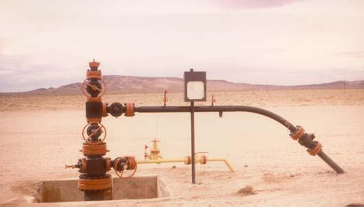
6 Libyan Gas Lift Well 6

7 Production Manifold in Libya 7

8 Libyan Gas Lift Tests 8
9 Continuous Flow Installation Design Based on Constant Decrease in Operating Injection-Gas Pressure for Each Succeeding Lower Gas Lift Valve All Gas Lift Valves have same port size. There is a constant decrease in the operating injection pressure for each succeeding lower valve. Port size that allows the injection-gas throughput for unloading and operating the well. 9
10 This installation design method is recommended for gas lift valves with small production-pressure pressure factors. When the ratio of the port area to the bellows area is low, the decrease in the injection gas pressure between gas lift valves, based on additional tubing effect pressure for the top valve, is not excessive. 10

11 Injection-Pressure Operated Gas Lift Valve Production Pressure factor = Ratio of Area of Port to Area of Bellows 11

12 Gas Lift Valve Specifications 12
13 The effect of bellows-assembly load rate on the performance of the valves is not considered in the installation design calculations. Safety factors included in these calculations should allow sufficient increase in the operating injection gas pressure, which is necessary to provide valve stem travel for adequate injection-gas passage through each successively lower unloading valve without interference from upper valves. 13
14 Selection of a constant injection- gas pressure decrease, or drop, in the surface operating injection pressure for each succeeding lower gas lift valve should not be arbitrary, as proposed in some design methods. The pressure decrease should be based on the gas lift valve specification to minimize the possibility of upper valves remaining open while lifting from a lower valve. 14
15 The additional tubing-effect pressure for the top gas lift valve is a logical choice for this decrease in the operating injection- gas pressure between valves. 15
16 Closing or reopening of an injection- pressure-operated gas lift valve is partially controlled by the production pressure effect, which is equal to the production pressure factor for the valve multiplied by the difference in flowing production pressure at the top valve depth. 16
17 The flowing pressure at an unloading- valve depth changes from the transfer pressure, ( (P ptfd ) min, To a higher flowing production pressure after the next lower valve becomes the operating pressure 17
18 The additional tubing-effect pressure is the difference between ( (P ptfd ) min, and the maximum flowing-production pressure at the unlading valve depth, (P ptfd ) max, after the point of gas injection has transferred to the next lower valve. 18
19 As the unloading gas lift valve depths increase, the distance between valves and the difference between ( (P ptfd ) min, and (P ptfd ) max decrease. Although the additional tubing-effect pressure decreases for lower valves, the injection-gas requirement for unloading increases with depth. 19
20 An increased stem travel, or stroke, is usually needed for the lower valves to generate the larger equivalent port area necessary for the higher injection gas requirements with the lower pressure differentials that occur across these deeper valves. 20
21 A constant decrease in the operating injection-gas pressure equal to the additional tubing effect pressure for the top valve allows a a greater increase in the injection gas above initial opening pressure for lower gas lift valves. 21
22 API Gas Lift Design 22

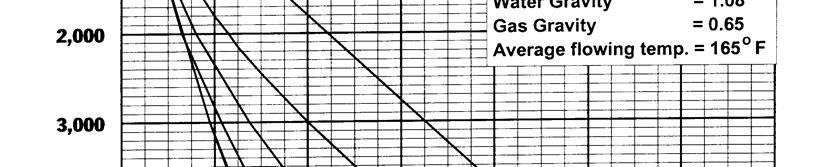
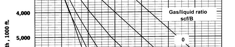
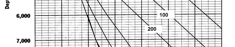
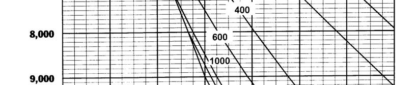
23 Gradient Curve 23
24 Gradient Curve 24
25 When the injection-gas pressure significantly exceeds the flowing- production pressure, an arbitrary increase in injection-gas gas-pressure, P io can be added to the initial production- pressure effect for the top valve for calculating the spacing and the initial opening pressures of the unloading gas lift valves 25
26 The total decrease in the injection-gas pressure is distributed equally between each successively lower gas lift valve rather than having a sizeable pressure drop across the operating gas lift valve or orifice-check check valve This reduces the possibility of multipoint injection through the upper unloading valves by ensuring that the valves remain closed after the point of gas injection has transferred to the next lower valve, 26
27 Determination of Valve Depths Because the final injection gas pressure is not known until the installation is designed, a pressure difference of 100 to 200 psi between the unloading P iod and P pfd traverses is assumed for locating the deepest valve depth. 27
28 Determination of Valve Depths The assumption of P iod -P pfd = 100 to 200 psi should ensure calculation of the operating valve depth. The static bottomhole pressure, P wsd and temperature, T wsd are usually referenced to the same depth, which is the lower end of the production conduit, D d. 28
29 Determination of Valve Depths Calculate the maximum unloading GLR based on the maximum injection gas rate available for unloading and the maximum daily design total fluid rate. 29
30 Well Information Tubing size = 2 7/8 in. OD Tubing Length, У = 6000 ft. Max. Valve Depth, D v(max) = 5970 ft. Static bottomhole pressure at D d, P wsd = 1800 psig at 6000ft. Daily production rate = 800 STB/D Water Cut = 50% Formation GOR = 500 scf/stb Oil Gravity = 35 o API Gas Gravity У g = 0.65 Produced-water specific gravity, У w = 1.08 Bottomhole temperature, T wsd =170 o F at 6000ft. Design unloading wellhead temperature, T whf = 100 o F. Load-fluid pressure gradient, g ls = 0.46 psi/ft. U-Tubing wellhead pressure, P whu = 100 psig. Flowing wellhead pressure, P whf = 100 psig. 30
31 Well Information Static fluid level = 0 ft. Surface kickoff injection-gas pressure, P ko = 1000 psig. Surface operating injection-gas pressure, P io = 1000 psig. Maximum unloading injection-gas rate, q giu = 800 Mscf/D. Operating daily injection-gas rate, q gi = 500 Mscf/D. Wellhead injection-gas temperature, T gio = 100 o F Assigned valve-spacing pressure differential at valve depth, P sd = 50 psi. Test rack valve temperature, T vo = 60 o F. Assigned minimum decrease in surface operating injection-gas pressure between valves, P io = 20 psi. Minimum distance between valves, D bv(min) = 150 ft. Gas lift valves : 1.5 inch O.D. nitrogen charged with A b = 0.77 in 2, and sharp edged seat. 31
32 Step 1: Calculate Maximum Unloading GLR R giu =q giu / q lt Where q giu = maximum unloading injection rate, Mscf/D, q lt = total liquid daily production rate, B/D, and R giu = maximum unloading GLR, scf/stb 32
33 Calculate Maximum Unloading GLR R giu =q giu / q lt = 800,000 scf/d / 800 STB/D R giu = 1000 scf/stb 33

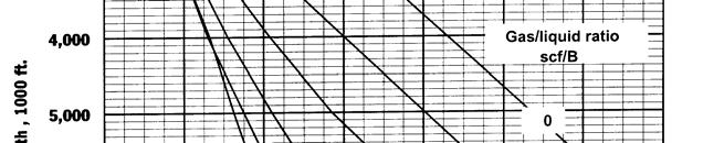
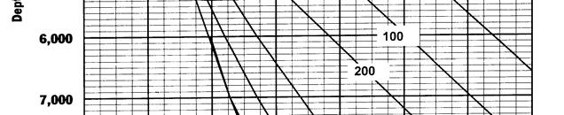

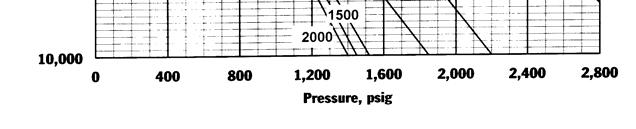
34 Step 2: Determine flowing Production pressure, P at pfd D d 34
35 Gradient Curve 35
36 Step 3:Calculate the unloading-flowing flowing- pressure-at at-depth gradient, g pfa above point of gas injection, g pf. g pfa = / 6000 g pfa = psi/ ft. 36
37 Step 4 Calculate the operating injection gas pressure at the lower end of the production conduit. where: P io = injection-gas pressure at surface, psia P iod = injection-gas pressure at depth, psia e = Napierian logarithm base = γ g = gas specific gravity (air = 1.0), dimensionless. D = true vertical depth of gas column, ft. bar T = average gas column temperature, R bar z = compressibility factor based on gas column average pressure P and temperature, T, dimensionless. 37
38 Step 4 P iod API Design Technique = 1154 psig at 6000 ft. = ( ) / 6000 =.0257psi/ft g gio = (1154 Since P iod - P pfd = = 254 psi Exceeds 200 psi, the maximum valve depth of 5970 ft can be attained. 38
39 Step 5: Calculate the unloading gas lift valve temperature at depth gradient, g Tvu. Bottomhole temperature, T wsd =170 o F at 6000ft. Design unloading wellhead temperature, whf = 100 o F at surface. T whf g Tvu = ( ) / 6000 = o F/ft. 39
 fluid pressure gradient, psi/ft = injection-gas pressure at depth gradient, psi/ft g gio Step 6: D v1 D v1 v1 =")
40 Step 6 D v1 = depth of top valve, ft P ko = surface kick-off or average field injection-gas pressure (optional), psig P whu = surface wellhead U-tubing U (unloading) pressure, psig PsD = assigned spacing pressure differential at valve depth, psi where g ls = static-load (kill) fluid pressure gradient, psi/ft = injection-gas pressure at depth gradient, psi/ft g gio Step 6: D v1 D v1 v1 = ( ) / ( ) v1 = 1957 ft. 40
41 Step 7 Calculate the minimum flowing-production pressure, (P pfd1 )min,, the injection-gas pressure, P iod1, and the unloading gas-lift valve temperature, T vud1, at the top valve depth by multiplying the appropriate gradient by the valve depth, D v1, and adding to the appropriate surface values (where n = 1 for top valve): 41
42 Step 7. Calculate the minimum flowing-production pressure, ( (P pfd 1)min, injection-gas pressure, PioD1,, and the unloading flowing temperature, T vud1 at D v1 of 1,957 ft as described on previous slide: (P pfd1 )min = (1,957) = 361 psig P iod1 = 1, (1,957) = 1,050 psig T vud1 = (1,957) = 123 F 42
43 API Design Technique Step 8 Calculate the depth of the second gas-lift valve, D v2, where n = 2 on the basis of the assigned minimum decrease in surface injection- gas pressure, p io, for spacing the gas-lift valves and the P iod -traverse. A valve spacing differential of around 20 to 30 psi will usually be sufficient for most 1.5-in. OD gas-lift valves. However, 1-in. 1 OD valves with large ports may require a higher, p io. This can be checked by calculating the additional production-pressure pressure effect, P pe1, after the valve depths are calculated for the assigned p io. 43
44 Step 8 API Design Technique (P pfd(n-1) 1)) min +g ls (D bv )=[P iod(n-1) Solve For D bv : D bv = P iod(n-1) [(n-1) 1) P io ]- (P pfd(n and D v(n) = D v(n-1) + D bv 1)-(n-1) 1) P io ]- P sd pfd(n-1) 1)) min sd +g gio (D bv ) min - P sd / ( (g ls ls g gio The decrease in surface injection-gas pressure for calculating D v2 is P io, and for D v3 is 2 ( P( io ), and for D v4 is 3 ( Pi( o ), and this procedure continues for each succeeding lower valve. 44
45 Step 8 API Design Technique Solve For D bv : D bv = P iod(n-1) [(n-1) 1) P io ]- (P pfd(n pfd(n-1) 1)) min min - P sd / ( (g ls ls g gio D bv = / ( ) = 1472 ft. and Dv(2) = D v(n-1) + D bv D v(2) = = 3429 ft. Repeat steps 7 and 8 for each valve location until reaching maximum depth 45
46 The calculated valve spacing for the sixth valve, D v6, would exceed the maximum valve depth, D v(max), of 5,970 ft. Because an orifice-check check valve will be placed in the bottom wireline-retrievable retrievable valve mandrel, no test-rack valve setting information is required. This completes the valve spacing calculations. 46
47 Graphical Representation 47
48 Determination of Gas-Lift Valve Port Size and Calculation of Test-Rack Opening Pressures. The gas-lift valves port ID and test-rack opening pressure calculations follow: Step 1. Determine the port size required for the gas-lift unloading valves and the operating orifice-check check valve orifice ID. The upstream injection-gas pressure, P 1, is based on P od5 of the last unloading valve corrected to the orifice-check check valve depth of 5970 ft: P 1 = 1, (5,970 5,762) = 1,073 psig at 5,970 ft 48
49 Determination of Gas-Lift Valve Port Size and Calculation of Test-Rack Opening Pressures. Step 1 (Continued) The downstream flowing-production pressure, P 2, is equal to the minimum flowing-production pressure at 5,970 ft. P 2 = (5,970) = 896 psig at 5,970 ft P ov = 1, = 177 psi across the orifice- check valve 49
50 Determination of Gas-Lift Valve Port Size and Calculation of Test-Rack Opening Pressures. Step 1 (Continued) From the Thornhill / Craver correlation, the required equivalent orifice size is near 14/64-in.; therefore, the next largest gas-lift valve port ID is 1/4-in. This size is sufficient for all of the upper unloading valves because they have a higher injection-gas operating pressure and a greater differential pressure between Pi od and pfd )min. (P pfd An equivalent orifice size of 12/64-in. to 13/64-in. is required to pass the operating injection-gas rate of 500 Mscf/D. 50
51 Determination of Gas-Lift Valve Port Size and Calculation of Test-Rack Opening Pressures. Step2 Record the valve specifications for a l.5-in. OD gas-lift valve having a 1/4-in. ID port with a sharp-edged seat where A b = 0.77 sq. in. from table: (A p/ A b ) = 0.064, (1 A p /A b ) = 0.936, and F p =
52 Determination of Gas-Lift Valve Port Size and Calculation of Test-Rack Opening Pressures. Step 3 Calculate P od1 P od1 = P iod1 where P iod1 = injection-gas pressure at valve depth, psig P od1 = injection-gas initial gas-lift valve opening pressure at valve depth, psig P od1 = 1,050 psig at 1,957 ft 52
53 Step4 API Design Technique Calculate the test-rack set opening pressure of the first valve (n = 1), P vo1, using Eqs and or 12.46: P bvd(n) = P od(n) (1-A p /A b )+ P pfd(n)min +(A p /A b ) P = C vo(n) T(n) (P bvd(n) ) / (1- A p /A b ) P vo(n) = 1050 (0.936)+361 (0.064) = 1006 psig. 53
54 Step 5 P = C vo(n) T(n) (P bvd(n) ) / (1- A p /A b ) for C T1 = (Calculated using T vud1 = 123 o F): vo1 = (1006)/0.936 = 942 psig at 60 o F P vo1 Step 6 Calculate the injection-gas initial opening pressure of the second gas-lift valve at depth (n = 2), P od(n) = P iod(n) (n-1) P io od(2) = = 1068 psig at 3429 ft. P od(2) 54
55 Step 7 Calculate the maximum flowing-production pressure opposite top unloading valve immediately after the point of gas injection has transferred to the second (lower) valve, (P pfd1 ) max. ( (P pfd1 ) max is shown graphically in Figure and can be calculated using the following equation: (P pfd1 ) max = P wf + Dv1 [(P od2 P whf )/D v2 ] (P pfd1 ) max = (( )/3429) (P pfd1 ) max = 652 psig at 1957 ft. 55
56 56
57 Step 8 Determine if the assumed decrease in surface injection- gas pressure, P io, is sufficient for the required gas-lift valve port size by calculating the additional production- pressure effect, P pe1, at the top valve: Ppe1 = F p [(P D1D1)max - P D1D1)min ] = (652 = 361 = 20 psi. P pe1 If P pe1 is less than or equal to the assumed P io proceed with the design. If P pe1 is greater than the assumed P io, then set P io = P pe1 and redo the spacing design. This is a conservative approach and many operators use actual operating experience to determine which P io to use. 57
58 Repeat Steps 6, 4 and 5 for remaining gas-lift valves: An orifice-check check valve is recommended for the sixth valve at 5,962 ft. The orifice ID should be 1/4-in. to pass sufficient gas to gas lift the well. A tabulation form for these calculations is given in table. 58
59 59
60 60
61 High Rate Continuous-Flow Installation Design ( Winkler) The application of the injection-gas rate throughput performance for injection-pressure pressure-operated gas-lift valves is illustrated in the high daily liquid rate continuous-flow installation design. The importance of valve performance data for high daily injection-gas rates is shown, and its unimportance for low injection-gas rate installation designs is illustrated. Valve performance data is of no value in selection of the top two unloading gas-lift valves in this installation. For these two upper valves, an assumed reasonable decrease in the surface injection-gas pressure of 20 psi for each valve ensures unloading the well and these upper valves remaining closed while lifting from a lower valve. When the required daily injection-gas rate increases for lifting from the third and fourth gas-lift valves, valve performance information becomes very important. A pressure vs. depth plot for this continuous-flow installation is shown in the Figure 61

62 High Rate Continuous-Flow Installation Design ( Winkler) 62
63 High Rate Continuous-Flow Installation Design (Winkler) Although the flowing-production transfer pressure traverse method for locating the depths of the valves may require an additional valve, or valves, in some installations, this design method has several advantages in wells requiring a high daily injection-gas rate for unloading. Because the injection-gas requirement to uncover the next lower valve is reduced, smaller valve ports can be used and the increase in the injection-gas pressure to stroke the valve stem is less. The unloading operations are faster because of the lesser difference in injection-gas requirement between unloading valves. 63
64 High Rate Continuous-Flow Installation Design ( Winkler) The surface origin and final downhole termination pressures for the flowing-production transfer pressure traverse are arbitrary. The 20% in this example for locating the surface transfer pressure traverse is widely used. The unloading injection-gas requirements for uncovering each lower valve increases as the percentage decreases and decreases as the percentages increase. The flowing-production transfer pressure at datum depth should be at least 100 to 200 psi less than the available design operating injection-gas pressure at the same depth 64
65 Simplified Mathematical Gas-Lift Valve Performance Model Because performance equations for specific gas-lift valves are not available from gas-lift valve manufacturers, a simplified gas-lift valve performance computer model was used to illustrate the calculations in this paper. The model is based on static force balance equations and several simplifying assumptions. This computer model describes qualitatively the injection-gas rate throughput of unbalanced, single-element element gas-lift valves using the Thornhill-Craver equation. 65
66 High Rate Design Data Tubing size = 4-1/24 1/2-in. OD (ID = in.) and Length = 6,000 ft Casing size = 8-5/88 5/8-in. OD, 44 lb/ft (ID = in.) Datum depth for bottomhole pressures and temperature, D d = 6,000 ft Bottomhole temperature at D d, T wsd = 170 of Shut-in (static) bottomhole pressure at D d, P wsd = 2,000 psig Maximum depth for bottom valve, D v(max ) = 5,900 ft Productivity index (gross liquid), PI = 6.3 BPD/psi Oil gravity = 35 o API (γ o = 0.850) Gas specific gravity (air = 1.0), γ g = 0.65 Water specific gravity, γ w = 1.08 Water fraction, f w = 0.50 (50%) Formation gas/oil ratio, R go = 400 scf/stb Formation gas/liquid ratio, R glf = 200 scf/stb Assigned minimum daily unloading production rate, q lu = 1,000 BPD Design total (oil + water) daily production rate, q lt = 5,000 BPD Wellhead U-tubing U unloading pressure, P whu = 100 psig Surface flowing wellhead pressure, P whf = 100 psig Static load (kill) fluid pressure gradient, g ls = psi/ft 66
67 High Rate Design Data (Continued) Surface operating injection-gas pressure, P io = 1,400 psig (at wellsite) Assigned daily injection-gas rate, q gi = 2,000 Mscf/day Unloading wellhead temperature, Twhu = 120 o F (basis for calculation of Pvo) Wellhead injection-gas temperature, Tgio = 120 o F Surface kickoff injection-gas pressure, Pko = 1,400 psig (at wellsite) Minimum assigned surface injection-gas pressure decrease between valves, P io = 20 psi (represents minimum surface injection-gas pressure increase for stroking gas-lift valve) Valve spacing design line percent factor at surface = 20% ( (f pt = 0.20) Minimum transfer-production pressure difference ( (P iod P ptd ) at D d, P ptd = 200 psi Valve spacing pressure differential at valve depth, P sd = 50 psi Minimum distance between valves D bv(min) = 400 ft Gas-lift valve test-rack setting temperature, T vo = 60 of Gas-lift valves: 1.5-in. OD wireline-retrievable, retrievable, unbalanced, single-element, element, nitrogen-charged bellows with A b = 0.77 in.2, B lr = 600 psi/in., and square sharp-edged seat. 67

68 Valve Performance First Valve 68

69 Valve Performance First Valve 69

70 Winkler High Rate Gas Lift Design 70
71 Continuous Flow Gas Lift Design As Presented in 2007 SPE PRODUCTION ENGINEERING HANDBOOK 71
A COMPARATIVE ANALYSIS OF CONTINUOUS GAS LIFT VALVE POSITIONING METHODS AND ITS APPLICATION WITH MS EXCEL & VBA
 A COMPARATIVE ANALYSIS OF CONTINUOUS GAS LIFT VALVE POSITIONING METHODS AND ITS APPLICATION WITH MS EXCEL & VBA Darsana Dutta, Palash Lochan Bordoloi, Pranjit Mahanta, Rajnib Borah, Sarmistha Roy Choudhury,
New 1.5 Differential Gas Lift Valve
 New 1.5 Differential Gas Lift Valve Steve Long Date: March 30, 2016 1 Introduction Background Information First differential valves used widely in 1930 s & 40 s 1944 King Injection Pressure Operated Valve
PRODUCTION I (PP 414) ANALYSIS OF MAXIMUM STABLE RATE AND CHOKES RESOLVE OF OIL WELLS JOSE RODRIGUEZ CRUZADO JOHAN CHAVEZ BERNAL
 ANALYSIS OF MAXIMUM STABLE RATE AND CHOKES RESOLVE OF OIL WELLS JOSE RODRIGUEZ CRUZADO JOHAN CHAVEZ BERNAL") PRODUCTION I (PP 414) SUBJECT: ANALYSIS OF MAXIMUM STABLE RATE AND CHOKES RESOLVE OF OIL WELLS BY: JOSE RODRIGUEZ CRUZADO JOHAN CHAVEZ BERNAL PROFESSOR MSc. LUIS ANTONIO DEL CASTILLO DE RODRIGUEZ LIMA,
PRODUCTION I (PP 414) SUBJECT: ANALYSIS OF MAXIMUM STABLE RATE AND CHOKES RESOLVE OF OIL WELLS BY: JOSE RODRIGUEZ CRUZADO JOHAN CHAVEZ BERNAL PROFESSOR MSc. LUIS ANTONIO DEL CASTILLO DE RODRIGUEZ LIMA,
SPE Copyright 2012, Society of Petroleum Engineers
 SPE 159645 Successful Application of Venturi Orifice Gas Lift Valve in Kaji-Semoga Field, South Sumatra: A Case Study Nova Arthur Rilian, SPE, Adam Fatchur Rohman, SPE, Kamal Hamzah, SPE, Yoseph Itok Arseto,
Using Valve Performance in Gas Lift Design Software
 32 nd Gas-Lift Workshop The Hague, The Netherlands February 2-6, 2009 Using Valve Performance in Gas Lift Design Software Tom Nations This presentation is the property of the author(s) and his/her/their
COPYRIGHT. Gas Lift Fundamentals. This section will cover the following learning objectives:
 Learning Objectives Gas Lift Fundamentals This section will cover the following learning objectives: Explain the role of gas lift in a real performance analysis process Explain the principles of multi-phase
GAS LIFT IN NEW FIELDS
 GAS LIFT IN NEW FIELDS GAS LIFT in NEW FIELDS NEW DESIGN FOR WELLS AND COMPRESSORS RESERVOIR AND PRODUCTION SIMULATION MATCHING REQUIRED PRODUCTION NODAL ANALYSIS SIMULATION USED TO SELECT INJECTION DEPTH
Design Tapered Electric Submersible Pumps For Gassy Wells Desheng Zhou, SPE, Rajesh Sachdeva, SPE, IHS INC.
 SPE 113661 Design Tapered Electric Submersible Pumps For Gassy Wells Desheng Zhou, SPE, Rajesh Sachdeva, SPE, IS INC. Copyright 8, Society of Petroleum Engineers This paper was prepared for presentation
Acoustic Liquid-Level Determination of Liquid Loading in Gas Wells
 Gas Well De-Liquification Workshop February 28 - March 2, 2005 Acoustic Liquid-Level Determination of Liquid Loading in Gas Wells Robert Lestz, Eddie Bruner Lynn Rowlan ChevronTexaco OBJECTIVE: 1. Observe
COMPARATIVE EVALUATION OF ARTIFICIAL LIFT METHODS ON A NIGER DELTA FIELD
 COMPARATIVE EVALUATION OF ARTIFICIAL LIFT METHODS ON A NIGER DELTA FIELD Okologume Chinedu Wilfred 1, Ofesi Samuel F. 2 1, 2 Department of Petroleum and Natural Gas Engineering, Federal University of Petroleum
32 nd Gas-Lift Workshop. Optimizing Subsea Well Kick-off Operations Case Study Using FlowLift2
 32 nd Gas-Lift Workshop The Hague, The Netherlands February 2-6, 2009 Optimizing Subsea Well Kick-off Operations Case Study Using FlowLift2 Denise Lima Artificial Lift Engineer Galileu de Oliveira Artificial
The Inflow Performance Relationship, or IPR, defines a well s flowing production potential:
 Artificial Lift Methods Artificial Lift Overview INTRODUCTION TO ARTIFICIAL LIFT The Inflow Performance Relationship, or IPR, defines a well s flowing production potential: (1) q = PI (Pavg - Pwf) where
Validation Study of Gas Solubility Correlations at bubble point pressure for Some Libyan Crude Oils Using Three chosen Correlations
 Validation Study of Gas Solubility Correlations at bubble point pressure for Some Libyan Crude Oils Using Three chosen Correlations Dr. Mustafa O. Sharrad Dept. of Chemical and Petroleum Engineering, Faculty
Challenging Subsea Gas Lift Application, Offshore Norway.
 Challenging Subsea Gas Lift Application, Offshore Norway. Authors: Magnus Paulsen - Schlumberger Artificial Lift, Norway Rina Stabell StatoilHydro, Norway Eric Lovie - Schlumberger Artificial Lift, Europe
FLOWING GRADIENTS IN LIQUID LOADED GAS WELLS
 Gas Well Deliquification Workshop Sheraton Hotel, Denver, Colorado February 27 March 2, 2011 FLOWING GRADIENTS IN LIQUID LOADED GAS WELLS O. Lynn Rowlan James N. McCoy Acoustic fluid level data Used to
STANDARD FOR CONTROL VALVE SEAT LEAKAGE
 11-3 STANDARD FOR CONTROL VALVE SEAT LEAKAGE 1. PURPOSE 1.1 This standard establishes a series of seat leakage classes for control valves and defines the test procedures. 2. SCOPE & LIMITATIONS 2.1 Selection
Section 2 Multiphase Flow, Flowing Well Performance
 Section 2 Multiphase Flow, Flowing Well Performance Multiphase Vertical Flow When producing an oil or gas well, the flow of the fluids up the tubing will be in most cases be 2 phase, liquid and gas. The
W I L D W E L L C O N T R O L PRESSURE BASICS AND CONCEPTS
 PRESSURE BASICS AND CONCEPTS Pressure Basics and Concepts Learning Objectives You will be familiarized with the following basic pressure concepts: Defining pressure Hydrostatic pressure Pressure gradient
Device Description. Operating Information. CP Q (eq. 1) GT. Technical Bulletin TB-0607-CFP Hawkeye Industries Critical Flow Prover
 GT. Technical Bulletin TB-0607-CFP Hawkeye Industries Critical Flow Prover") A compressible fluid traveling at subsonic velocity through a duct of constant cross section will increase velocity when passing through a region of reduced cross-sectional area (in this case, an orifice)
A compressible fluid traveling at subsonic velocity through a duct of constant cross section will increase velocity when passing through a region of reduced cross-sectional area (in this case, an orifice)
Gas Locked Pumps are NOT Gas Locked!
 9 th Annual Sucker Rod Pumping Workshop Renaissance Hotel Oklahoma City, Oklahoma September 17-20, 2013 Gas Locked Pumps are NOT Gas Locked! Lynn Rowlan Ken Skinner Echometer Company Introduction Gas Locked
then the work done is, if the force and the displacement are in opposite directions, then the work done is.
 1. What is the formula for work? W= x 2. What are the 8 forms of energy? 3. Write the formula for the following: Kinetic Energy Potential Energy 4. If the force and the displacement are in the same direction,
Gas Gathering System Modeling The Pipeline Pressure Loss Match
 PETROLEUM SOCIETY CANADIAN INSTITUTE OF MINING, METALLURGY & PETROLEUM PAPER 2005-230 Gas Gathering System Modeling The Pipeline Pressure Loss Match R.G. MCNEIL, P.ENG. Fekete Associates Inc. D.R. LILLICO,
1. INTRODUCTION. International Journal of Students Research in Technology & Management Vol 1 (05), September 2013, ISSN , pg
, September 2013, ISSN , pg") DESIGN OF A GAS LIFT SYSTEM TO INCREASE OIL PRODUCTION FOR OFFSHORE WELLS WITH HIGH WATER CUT Saurabh Kumar B.Tech (Petroleum Engineering) Indian School of Mines University, Dhanbad saurabhsuman1702@gmail
DESIGN OF A GAS LIFT SYSTEM TO INCREASE OIL PRODUCTION FOR OFFSHORE WELLS WITH HIGH WATER CUT Saurabh Kumar B.Tech (Petroleum Engineering) Indian School of Mines University, Dhanbad saurabhsuman1702@gmail
3 1 PRESSURE. This is illustrated in Fig. 3 3.
 P = 3 psi 66 FLUID MECHANICS 150 pounds A feet = 50 in P = 6 psi P = s W 150 lbf n = = 50 in = 3 psi A feet FIGURE 3 1 The normal stress (or pressure ) on the feet of a chubby person is much greater than
Downhole Gas Separator Selection
 4th Annual Appalachian Basin Gas Well Deliquification Workshop Marietta College, Marietta, Ohio June 3 5, 2013 Downhole Gas Separator Selection Lynn Rowlan Proper Downhole Gas Separator Selection Critical
Rupture Disc Sizing for Micro Motion Coriolis Sensors
 Rupture Disc Sizing for Micro Motion Coriolis Sensors www.emerson.com/micromotion Rupture Disc Sizing White Paper 1 Introduction Emerson s Micro Motion Coriolis flow meters are widely used in many industries
COPYRIGHT PETROSKILLS
 Production Electrical Submersible Pumps Fundamentals Virtual Session 2 ESP Design Example Manual Design 1 Production ESP Design and Equipment Selection: Nine Steps** 1. Basic data 2. Production capacity
International Journal of Petroleum and Geoscience Engineering Volume 03, Issue 02, Pages , 2015
 International Journal of Petroleum and Geoscience Engineering Volume 03, Issue 02, Pages 116- ISSN: 2289-4713 Improving Reservoir Recovery Factor Using Enhanced Electrical Submersible Pump Design; a Case
Downhole Gas Separators
 Gas Well De-Liquification Workshop Denver, Colorado February 27 March1, 2006 Downhole Gas Separators A Laboratory and Field Study Jim McCoy, Echometer Company Tony Podio, University of Texas at Austin
NORDCALC Introduction... 2 Registration... 2 Flow Calculations tab Torque Calculation & Actuator Mounting Data tab... 21
 NORDCALC User Guide Table of Contents NORDCALC Introduction... 2 Registration... 2 Flow Calculations tab... 5 Calculating the gas flow rate for gaseous medium... 6 Calculating the pressure drop for gaseous
Acoustic Liquid Level Testing of Gas Wells
 European Conference Gas Well Deliquification 28-30 September 2009, Hampshire Hotel, The Netherlands Acoustic Liquid Level Testing of Gas Wells Originally Presented OKC POS 2009 - SPE 120643 Lynn Rowlan
Vapor Recovery from Condensate Storage Tanks Using Gas Ejector Technology Palash K. Saha 1 and Mahbubur Rahman 2
 37 Journal of Chemical Engineering, IEB Vapor Recovery from Condensate Storage Tanks Using Gas Ejector Technology Palash K. Saha 1 and Mahbubur Rahman 2 Abstract 1 Bibyana Gas Field 2 Department of Petroleum
No E. General Information. Averaging Pitot Tube Flow Sensor HITROL CO., LTD.
 No. 2000-03E Averaging Pitot Tube Flow Sensor HITROL CO., LTD. M e a s u r e m e n t Pr i n c i p l e Measurement principle of Hitbar sensor is explained below. When a Hitbar is installed in the pipeline
Bubble Tube Installations
 Instruction MI 020-328 September 2013 Bubble Tube Installations For Liquid Level, Density, and Interface Level Measurements 2 Contents Introduction... 5 Abbreviations... 5 Principle of Operation... 5 Alternative
Evaluation of Three Different Bubble Point Pressure Correlations on Some Libyan Crude Oils
 Evaluation of Three Different Bubble Point Pressure Correlations on Some Libyan Crude Oils Dr. Mustafa O. Sharrad, Dr.Hosam H. M. Almahrog Dr. Emhemed A. Aboraema Dept. of Chemical and Petroleum Engineering,
CONTROL VALVE SEAT LEAKAGE
 ANSIIFCI 70-2-2006 AMERICAN NATIONAL STANDARD CONTROL VALVE SEAT LEAKAGE \D o N I N I o ~ H U ~ H [/) ~ Fluid Controls Institute, Inc. Spo~sor: Fluid Controls institute, inc. 1300 Sumner Ave Cleveland,
VortexFlow DX (Downhole) Tool Installation Instructions
 Tool Installation Instructions") VortexFlow DX (Downhole) Tool Installation Instructions www.vortextools.com Page 1 of 10 The VortexFLOW tools are based upon Technology that is a result of U.S.A. patents 6,151,751; 6,659,118; 6,749,374;
VortexFlow DX (Downhole) Tool Installation Instructions www.vortextools.com Page 1 of 10 The VortexFLOW tools are based upon Technology that is a result of U.S.A. patents 6,151,751; 6,659,118; 6,749,374;
Dynamic IPR and Gas Flow Rate Determined for Conventional Plunger Lift Well
 Gas Well Deliquification Workshop Sheraton Hotel, Denver, Colorado February 17 20, 2013 Dynamic IPR and Gas Flow Rate Determined for Conventional Plunger Lift Well Lynn Rowlan Determine Plunger Lift Gas
Pump Fillage Problem Overview. Jim McCoy. 9 th Annual Sucker Rod Pumping Workshop. Renaissance Hotel Oklahoma City, Oklahoma September 17-20, 2013
 9 th Annual Sucker Rod Pumping Workshop Renaissance Hotel Oklahoma City, Oklahoma September 17-20, 2013 Pump Fillage Problem Overview Jim McCoy Lynn Rowlan Tony Podio Ken Skinner Echometer Company Jim@echometer.com
Presented By Dr. Youness El Fadili. February 21 th 2017
 Presented By Dr. Youness El Fadili February 21 th 2017 Outline Introduction Objective Critical rate definition Theory and development of New model Application and comparison of the New model Experimental
This portion of the piping tutorial covers control valve sizing, control valves, and the use of nodes.
 Piping Tutorial A piping network represents the flow of fluids through several pieces of equipment. If sufficient variables (flow rate and pressure) are specified on the piping network, CHEMCAD calculates
2007 Gas-Lift Workshop
 2007 Gas-Lift Workshop Field Application of Automation and Control Equipment by Cleon Dunham Oilfield Automation Consulting 2/11/2007 2007 Gas-Lift Workshop 1 Gas-Lift Automation & Control Equipment Outline
Gas Lift Challenges. Gas-Lift Workshop. Qatar February 4-8, Mike Johnson ExxonMobil Production Company
 Gas-Lift Workshop Qatar February 4-8, 2007 Gas Lift Challenges Mike Johnson ExxonMobil Production Company This presentation is the property of the author(s) and his/her/their company(ies). It may not be
Advanced Intermittent Gas Lift Utilizing a Pilot Valve
 Gas Well Deliquification Workshop Sheraton Hotel, Denver, Colorado February 29 March 2, 2016 Advanced Intermittent Gas Lift Utilizing a Pilot Valve Matt Young Technical Sales Manager Intermittent Gas Lift
Leak testing of Valves. Standards for acceptable Rates of Valve Leakage
 Leak testing of Valves Standards for acceptable Rates of Valve Leakage American Petroleum Institute (API) The API standard 598: Valve Inspection and Testing, covers the testing and inspection requirements
44 (0) E:
 E:") FluidFlow Relief Valve Sizing Handbook Flite Software 2016 Flite Software N.I. Ltd, Block E, Balliniska Business Park, Springtown Rd, Derry, BT48 0LY, N. Ireland. T: 44 (0) 2871 279227 E: sales@fluidflowinfo.com
FluidFlow Relief Valve Sizing Handbook Flite Software 2016 Flite Software N.I. Ltd, Block E, Balliniska Business Park, Springtown Rd, Derry, BT48 0LY, N. Ireland. T: 44 (0) 2871 279227 E: sales@fluidflowinfo.com
Demystifying ESPs: A technique to make your ESP talk to you.
 6 th European Electric Submersible Pump Round Table Aberdeen Section Demystifying ESPs: A technique to make your ESP talk to you. A.J. (Sandy) Williams (Phoenix Petroleum Services) Abstract Using a diagnostic
A Successful Experience in Optimization of a Production Well in a Southern Iranian Oil Field
 Iranian Journal of Chemical Engineering Vol. 6, No. 2 (Spring), 2009, IAChE A Successful Experience in Optimization of a Production Well in a Southern Iranian Oil Field S. R. Shadizadeh, M. Zoveidavianpoor
International Journal of Technical Research and Applications e-issn: , Volume 4, Issue 3 (May-June, 2016), PP.
, PP.") DESIGN AND ANALYSIS OF FEED CHECK VALVE AS CONTROL VALVE USING CFD SOFTWARE R.Nikhil M.Tech Student Industrial & Production Engineering National Institute of Engineering Mysuru, Karnataka, India -570008
DESIGN AND ANALYSIS OF FEED CHECK VALVE AS CONTROL VALVE USING CFD SOFTWARE R.Nikhil M.Tech Student Industrial & Production Engineering National Institute of Engineering Mysuru, Karnataka, India -570008
Gas Well Deliquification Workshop. Sheraton Hotel, Denver, Colorado February 29 March 2, 2016
 Gas Well Deliquification Workshop Sheraton Hotel, February 29 March 2, 2016 Enriched Inflow Performance Relationship (EIPR) Curves for Simultaneous Selection of Target Rate & Pump Setting Depth While Visualizing
PETROLEUM ENGINEERING 310 SECOND EXAM. October 23, 2002
 PETROLEUM ENGINEERING 310 SECOND EXM October 23, 2002 Ground Rules Do all your work on the test paper and the space provided for the answer, do no write on the back. Grading will be based on approach and
FUNDAMENTALS OF PRESSURE REGULATORS ROBERT BENNETT MANAGER OF TRAINING ELSTER AMERICAN METER
 FUNDAMENTALS OF PRESSURE REGULATORS ROBERT BENNETT MANAGER OF TRAINING ELSTER AMERICAN METER SUPPLY = DEMAND FUNCTION OF A REGULATOR A regulator may be defined as a "mechanism for controlling or governing
VB-7212 Series. Application. Features. Applicable Literature. 5/8" O.D., 45 SAE Flared Stem Up Open, Two-Way Valves General Instructions
 VB-7212 Series 5/8" O.D., 45 SAE Flared Stem Up Open, Two-Way Valves General Instructions Application VB-7212 series single seat, stem up open, two-way valves control water from 20 to 281 F (-7 to 138
Pressure Measurement
 Pressure Measurement Absolute and Gage Pressure P abs = P gage + P atm where P abs = Absolute pressure P abs = Gage pressure P abs = atmospheric pressure A perfect vacuum is the lowest possible pressure.
Application of Expansive Soil Geotechnical Procedures
 Application of Expansive Soil Geotechnical Procedures FPA PRESENTATION John T. Bryant, Ph.D., P.G., P.E with Robert L. Lytton, Ph.D., PE. And Mr. Dean Read HOUSTON, TEXAS WEDNESDAY DECEMBER 10, 2008 2008
γ water = 62.4 lb/ft 3 = 9800 N/m 3
 CEE 42 Aut 200, Exam #1 Work alone. Answer all questions. Always make your thought process clear; if it is not, you will not receive partial credit for incomplete or partially incorrect answers. Some data
On-Off Connector Skirt
 On-Off Connector Skirt Retrievable Packers & Accessories The On-Off Connector Skirt is compact, reliable, fully sealing, J-type tubing disconnect device that automatically engages and releases with a small
Jim McCoy. Tubing Anchor Effect on Pump Fillage. Lynn Rowlan Tony Podio Ken Skinner. Gas Well Deliquification Workshop.
 Gas Well Deliquification Workshop Sheraton Hotel, February 23 26, 2014 Tubing Anchor Effect on Pump Fillage Jim McCoy Jim@echometer.com Lynn Rowlan Tony Podio Ken Skinner Gas Separator Overview Natural
Sarah N. S. All-Said Noor * ; Dr. Mohammed S. Al-Jawad ** ; Dr. Abdul Aali Al- Dabaj ***
 Sarah N. S. All-Said Noor * ; Dr. Mohammed S. Al-Jawad ** ; Dr. Abdul Aali Al- Dabaj *** * Exploration petroleum company, ** University of Technology, ***Ministry of Oil The behavior of pressure derivative
PRESSURE REGULATOR PRESSURE REDUCING. APPLICATION: Regulation of inlet pressure to gas compressors. Control of supply or distribution system pressure
 PRESSURE REGULATOR PRESSURE REDUCING APPLICATION: Regulation of inlet pressure to gas compressors. Control of supply or distribution system pressure PRESSURE RANGE: Ductile Iron: Upstream: psig to 125
Pressure Control. where: p is the pressure F is the normal component of the force A is the area
 Pressure Control First of all, what is pressure, the property we want to control? From Wikipedia, the free encyclopedia. Pressure is the application of force to a surface, and the concentration of that
Gerald D. Anderson. Education Technical Specialist
 Gerald D. Anderson Education Technical Specialist The factors which influence selection of equipment for a liquid level control loop interact significantly. Analyses of these factors and their interactions
Process Dynamics, Operations, and Control Lecture Notes - 20
 Lesson 0. Control valves 0.0 Context Controller output is a signal that varies between 0 and 100%. Putting this signal to use requires a final control element, a device that responds to the controller
Gas Lift Valve Testing
 36 th Gas-Lift Workshop Stavanger, Norway February 4 8, 2013 Gas Lift Valve Testing Angel Wileman, Research Engineer Southwest Research Institute, Fluid Dynamics Feb. 4 8, 2013 2013 Gas-Lift Workshop 1
Gas Lift Optimization Using Smart Gas Lift Valve
 Gas Lift Optimization Using Smart Gas Lift Valve Mohamed A. G. H. Abdalsadig, Amir Nourian, G. G. Nasr, M. Babaie 1 Abstract Gas lift is one of the most common forms of artificial lift, particularly for
A Combined Experimental & Numerical Research Program to Develop a Computer Simulator for Intermittent Gas-lift
 37 th Gas-Lift Workshop Houston, Texas, USA February 3 7, 2014 A Combined Experimental & Numerical Research Program to Develop a Computer Simulator for Intermittent Gas-lift Bordalo, S. (1), Barreto, M.
VB-7213 Series. Application. Features. Applicable Literature. 1/2" to 2" Screwed NPT Stem Up Open, Two-Way Valves General Instructions
 VB-7213 Series 1/2" to 2" Screwed NPT Stem Up Open, Two-Way Valves General Instructions Application VB-7213 series single seat, stem up open, two-way valves control water from 20 to 281 F (-7 to 138 C)
Lesson 6: Flow Control Valves
 : Flow Control Valves Basic Hydraulic Systems Hydraulic Fluids Hydraulic Tank Hydraulic Pumps and Motors Pressure Control Valves Directional Control Valves Flow Control Valves Cylinders : Flow Control
Downhole Diverter Gas Separator
 7 th Annual Sucker Rod Pumping Workshop Renaissance Hotel Oklahoma City, Oklahoma September 27-30, 2011 Downhole Diverter Gas Separator Jim McCoy Ken Skinner, Lynn Rowlan, Dieter Becker - Echometer Company
Intermittent Gas Lift Utilizing a Pilot Valve
 39 th Gas-Lift Workshop Houston, Texas, USA May 16 20, 2016 Intermittent Gas Lift Utilizing a Pilot Valve Matt Young Technical Sales Manager May 16 20, 2016 2015 Gas-Lift Workshop 1 Intermittent Gas Lift
THE TRANSIENT GAS LIFT SIMULATOR IN PROSPER (IPM10.0)
") Page 1 INTRODUCTION In IPM 10.0 one of the new features is the ability to perform Transient Gas Lift Designs, and this article is designed to provide the context behind the development whilst also showing
Page 1 INTRODUCTION In IPM 10.0 one of the new features is the ability to perform Transient Gas Lift Designs, and this article is designed to provide the context behind the development whilst also showing
Contact Information. Progressive Optimization Service. We Provide: Street Bay #2. Grande Prairie, AB T8V - 4Z2
 Progressive Optimization Services (P.O.S.) is an Oil and Gas Optimization Service company based out of Grande Prairie, Alberta with offices in Edson, Alberta and Ft St John British Columbia our operations
Sizing Pulsation Dampeners Is Critical to Effectiveness
 Sizing Pulsation Dampeners Is Critical to Effectiveness Pressure variation is an important consideration when determining the appropriate size pulsation dampener needed for an application. by David McComb,
Air Operated Hydraulic Pumping Systems to 50,000 psi
 High Pressure Equipment Air Operated Hydraulic Pumping Systems to 50,000 psi PS-10: 10,000 psi PS-20: 20,000 psi PS-30: 30,000 psi PS-40: 40,000 psi PS-50: 50,000 psi PS-90: 90,000 psi High Pressure air
Electrical Submersible Pump Analysis and Design
 Electrical Submersible Pump Analysis and Design May 30, 2001 Abstract Case Services software provides production optimization for a variety of different methods of artificial lift. This paper discusses
Bridging the Gap Using Gas Assisted Plunger Li5 (GAPL) Presented By: Todd Thrash Technical Data Provided By: Rusty Brown, P.E.
 Presented By: Todd Thrash Technical Data Provided By: Rusty Brown, P.E.") Bridging the Gap Using Gas Assisted Plunger Li5 (GAPL) Presented By: Todd Thrash Technical Data Provided By: Rusty Brown, P.E. Overview What is GAPL? Advantages of GAPL Produc7on Analysis A technical review
Bridging the Gap Using Gas Assisted Plunger Li5 (GAPL) Presented By: Todd Thrash Technical Data Provided By: Rusty Brown, P.E. Overview What is GAPL? Advantages of GAPL Produc7on Analysis A technical review
VB-7211 Series. Application. Features. Applicable Literature. 1/2" to 1-1/4" Union End NPT Stem Up Open, Two-Way Valves General Instructions
 TAC 1354 Clifford Avenue P. O. Box 2940 Loves Park, IL 61132-2940 www.tac.com VB-7211 Series 1/2" to 1-1/4" Union End NPT Stem Up Open, Two-Way Valves General Instructions Application VB-7211 series stem
Chapter 8: Reservoir Mechanics
 PTRT 1472: Petroleum Data Management II Chapter 8: Reservoir Mechanics - Reservoir drives Types of Natural Gas Reservoir Fluids Natural gas is petroleum in a gaseous state, so it is always accompanied
4 RESERVOIR ENGINEERING
 4 RESERVOIR ENGINEERING This chapter summarizes the reservoir engineering data and analysis used in the development of the Depletion Plan for the White Rose Field. The data were derived from seismic and
Downhole Gas Separator Selection
 Gas Well Deliquification Workshop Sheraton Hotel, February 17 20, 2013 Downhole Gas Separator Selection James N. McCoy & Lynn Rowlan Feb. 17 20, 2013 2 Downhole Gas Separator Selection Many operators with
1 PIPESYS Application
 PIPESYS Application 1-1 1 PIPESYS Application 1.1 Gas Condensate Gathering System In this PIPESYS Application, the performance of a small gascondensate gathering system is modelled. Figure 1.1 shows the
Casing Design. Casing Design. By Dr. Khaled El-shreef
 Casing Design By Dr. Khaled El-shreef 1 Casing Design CONTENTS Function of Casing Casing Types & Tools Strength Properties Casing Specification Casing Design 2 1 RUNNING AND CEMENTING CASING Reasons for
The Discussion of this exercise covers the following points:
 Exercise 3-2 Orifice Plates EXERCISE OBJECTIVE In this exercise, you will study how differential pressure flowmeters operate. You will describe the relationship between the flow rate and the pressure drop
Understanding pressure and pressure
 CHAPTER 1 1-1 PRESSURE BASICS Remember to think downhole. The concepts provided in this section cover the foundations for good well control. Understanding pressure and pressure relationships is important
Downhole Gas Separation Performance
 Gas Well Deliquification Workshop Sheraton Hotel, February 20 22, 2017 Downhole Gas Separation Performance Lynn Rowlan Overview Free gas interfering with liquid filling the pump is a major operational
Application Worksheet
 Application Worksheet All dimensions are nominal. Dimensions in [ ] are in millimeters. Service Conditions Medium Through Valve: Required C v : Temperature Maximum: Minimum: Normal: Flow Maximum: Minimum:
VBS-9263 Series. Application. Features. Applicable Literature
 TAC 1354 Clifford Avenue P. O. Box 2940 Loves Park, IL 61132-2940 www.tac.com VBS-9263 Series 1/2" and 3/4" Screwed NPT 316 Stainless Steel Stem Up Closed, Two-Way Valves General Instructions Application
DISCLAIMER OF WARRANTIES AND LIMITATION OF LIABILITIES
 DISCLAIMER OF WARRANTIES AND LIMITATION OF LIABILITIES THIS REPORT WAS PREPARED BY THE ORGANIZATION(S) NAMED BELOW. NEITHRE THE ORGANIZATION(S) BELOW, NOR ANY PERSON ACTING ON BEHALF OF THEM: (A) MAKES
Pasquale Imbò e Marco Pelucchi ENI S.pA;
 7th European Gas Well Deliquification Conference Innovative Failsafe Capillary Injection System Resolves Liquid Loading in Gas Well with a Cost- Effective Solution that Maintaining Production and Well-Safety
Hydro-Mech Bridge Plug
 Manual No: 0620000303 Revision: F Approved By: Quality Engineer Date: 2014-9-9 Hydro-Mech Bridge Plug DESCRIPTION: Map Hydro-Mech Bridge Plug is hydraulically actuated and mechanically set. Compact, with
Plunger Fall Velocity Model
 Gas Well Deliquification Workshop Sheraton Hotel, Denver, Colorado February 19 22, 2012 Plunger Fall Velocity Model Lynn Rowlan & James N. McCoy James F Lea Rick Nadkrynechny Carolyn Cepuch What s know
Introduction to Artificial Lift Methods COPYRIGHT. Gas Lift and ESP Pump Core. This section will cover the following learning objectives:
 Learning Objectives Introduction to Artificial Lift Methods Gas Lift and ESP Pump Core This section will cover the following learning objectives: Identify the most common artificial lift technologies employed
Colorado Oil and Gas Conservation Commission (COGCC) Completed Interval Report, Form 5A Data Field Definitions
 Completed Interval Report, Form 5A Data Field Definitions") NOTE: Changes to the Form 5A, effective June 1, 2012, to accommodate the disclosure requirements are indicated by a preceding asterisk (*) and bold italics. All other fields are unchanged. FORM 5A HEADING
NOTE: Changes to the Form 5A, effective June 1, 2012, to accommodate the disclosure requirements are indicated by a preceding asterisk (*) and bold italics. All other fields are unchanged. FORM 5A HEADING
Beam Pumping to Dewater Horizontal Gas Wells
 2 nd Annual Appalachian Basin Gas Well Deliquification Seminar Hilton Garden Inn, Pittsburg, PA June 13-14, 2011 Beam Pumping to Dewater Horizontal Gas Wells Lynn Rowlan, Echometer Co. J F Lea, Production
Comments on Homework. Class 4 - Pressure. Atmospheric Pressure. Gauge vs. Absolute Pressure. 2. Gauge vs. Absolute Pressure. 1.
 Class 4 - Pressure 1. Definitions 2. Gauge Pressure 3. Pressure and Height of Liquid Column (Head) 4. Pressure Measurement and Manometers Please don t forget the special problem for the next HW assignment
VB-7263 Series. Application. Features. Applicable Literature
 TAC 1354 Clifford Avenue P. O. Box 2940 Loves Park, IL 61132-2940 www.tac.com VB-7263 Series 1/2" to 2" Screwed NPT Stainless Steel Trim with Teflon Disc Stem Up Closed, Two-Way Valves General Instructions
HydroPull. Extended-Reach Tool. Applications
 Extended-Reach Tool HydroPull This tool incorporates a cycling valve that momentarily interrupts the flow to create water-hammer pressure pulses inside coiled or jointed tubing used in horizontal well
WellTracer. East Texas Gas Producers Association. Carthage, Texas September 21 st, 2010
 WellTracer East Texas Gas Producers Association Carthage, Texas September 21 st, 2010 Welltracer Gas Lift Diagnostics What methods are available for diagnosing leak points and or gas lift efficiency? Diagnostic
Gas viscosity ( ) Carr-Kobayashi-Burrows Correlation Method Lee-Gonzalez-Eakin Method. Carr-Kobayashi-Burrows Correlation Method
 Carr-Kobayashi-Burrows Correlation Method Lee-Gonzalez-Eakin Method. Carr-Kobayashi-Burrows Correlation Method") Gas viscosity The viscosity of a fluid is a measure of the internal fluid friction (resistance) to flow. If the friction between layers of the fluid is small, i.e., low viscosity, an applied shearing force
Gas viscosity The viscosity of a fluid is a measure of the internal fluid friction (resistance) to flow. If the friction between layers of the fluid is small, i.e., low viscosity, an applied shearing force
Cased-Hole Logging Environment
 Cased-Hole Logging Environment 2 Planning a Production Logging Job Planning is an important part of a production logging job. Frequently these jobs can only be done in safety during daylight. Thus, the