Powers Controls D Day-Night Thermostats
|
|
|
- Nelson Marsh
- 6 years ago
- Views:
Transcription
 and the night setting controls when the supply pressure is 25 psi")
1 Powers Controls D Day-Night Thermostats Technical Instructions Document No P25 TH Description The D Day-Night or Two Temperature Thermostat is available as a room-type instrument. It is essentially two thermostats incorporated into one unit: The day setting controls when the supply pressure is 18 psi (124 kpa) and the night setting controls when the supply pressure is 25 psi (172 kpa). This thermostat is available with remote changeover of the supply air pressure. A manual reset lever is provided to allow any individual thermostat to control at its normal day setting while the balance of the system is operating on night control. Also, this manual reset lever can be moved to permit this particular thermostat to be reset to return it to night operation. When the system is changed back to day operation, all thermostats revert to automatic changeover. Application The D day-night Thermostat with remote changeover is recommended for temperature control of radiation, mixing dampers or unit ventilators in schools, residences, offices and hospitals. It is particularly applicable where all rooms or offices in a zone are vacated at approximately the same time and a lower control temperature is desired at night. Changeover from day to night and vice versa (see Operation) can be obtained by means of a zone "day-night" selector switch or by use of a program clock. The program clock will automatically set all thermostats for day operation at a selected hour in the morning and automatically change the system to night operation at some predetermined hour in the evening. Product Numbers Table 1. Product Number Description Key Set Point Adjustment with Thermometer Concealed Set Point Adjustment with Thermometer
2 Technical Instructions Document Number P25 D Day-Night Thermostats Specifications Typical Specifications Control Action Direct Acting Operating Range Day 60 to 80 F (15 to 26 C) Night 50 to 70 F (10 to 21 C) Operating Pressure 30 psi (206.8 kpa) Max. Sensitivity Fixed 2.5 psi per F (31.0 kpa per C) Temperature Response 0.5 F (0.3 C) Maximum Ambient Temperature 125 F (51.5 C) Dial Graduations (Day & Night) 2 F (1.1 c) Normal Air Supply Pressure Day 18 psi (124.1 kpa) Night 25 psi (172.4 kpa) Dimensions 2-7/8" x 5-5/8" x 2-3/16" deep (73 mm x 143 mm x 56 mm) Weight 5 lbs. (2.3 kg) Cover Style Key or Concealed Set Point Adjustment Cover Finish Silver is standard (other finishes on special order). All day-night thermostats shall be equipped with a volatile liquid type sensing element, shall be capable of operating on a change of plus or minus 1/2 F, (0.3 C) and shall be of the gradual type capable of positioning valves or dampers in intermediate positions. Day-night thermostats shall be of the non-bleed type so that no air shall be used except when positioning a valve or damper motor. Day-night thermostats shall be provided with two dials: on the day cycle the range shall be adjustable from 60 to 80 F (15 to 26 C); on the night cycle from 50 to 70 F (10 to 21 C). Changeover from day temperature to night temperature shall be accomplished pneumatically by remote change of the supply pressure. A manual reset lever shall be provided to allow any individual thermostat to control at its normal day setting while the balance of the system is operating on the night setting. This reset lever must also be capable of being manually returned to night setting. Operation (See Figure 1) By use of the special key furnished, the thermostat can be adjusted for desired day operation and for desired night operation. A day setting of from 60 to 80 F (15 to 26 C) or a night adjustment of 50 to 70 F (10 to 21 C) can be obtained. A thermostatic disc is attached to an adjustment lever which pivots on a pin. The action of the disc is controlled by either adjustment post or, depending on whether thermostat is operating on "day" pressure or "night" pressure. With the adjustment lever against the adjustment post, a decrease in temperature causes the thermostatic disc to contract. This moves the control lever and the adjusting screw away from the exhaust valve assembly. The exhaust valve opens and gradually decreases the branch return pressure from the thermostat. This decrease of control pressure opens the valve on the heating supply, or the hot blade of a mixing damper, to satisfy room temperatures. NOTE: When the exhaust valve is open, the supply valve is held closed by the supply valve spring, so that there is no constant waste of air. Page 2
3 D Day-Night Thermostats Operation, Continued Technical Instructions Document Number P25 With a rise in room temperature, the thermostatic disc expands forcing the control lever to close the exhaust valve assembly and open the supply valve. Branch return pressure then increases to throttle the heat supply. The air supply port also connects the supply valve chamber to the piston plate diaphragm chamber which acts on the piston plate. When the supply pressure is raised from the day setting of 18 psi (124 kpa) to the night setting of 25 psi, (172 kpa), the piston plate forces the piston plate extension against the adjustment lever. The adjustment lever then pivots and operates from the night adjustment post. Operation on the night setting and day setting is the same except for a different control point. Field Calibration Day setting - System supply pressure 18 psi (124 kpa) 1. Check the day air pressure reducing valve to be sure it is maintaining an 18 psi day pressure. 2. With actual room temperature within 5 F (2.7 C) plus or minus of set point of thermostat, the cover should be removed using the special key enclosed in the thermostat kit. 3. Loosen test screw one complete turn and immediately slip on the rubber tubing of the test gauge assembly. 4. Adjust the day dial to the actual room temperature. The test gauge should then read 7-1/2 psi (51.7 kpa) plus or minus 1-1/2 psi (10.3 kpa). If this is not the case, turn the adjusting post in either direction until it does read approximately 7-1/2 psi (51.7 kpa). Loosen the day dial retaining screw and reset the day temperature dial to the correct room temperature. Retighten dial retainer screw being careful not to change the setting of adjustment post. Be careful not to come in contact with thermostatic disc. Wait several minutes after installing test gauge hose before actually making recalibration. 5. Breathe onto the thermostatic disc and note whether branch pressure increases. If there is no rise in branch pressure, the thermostat is not functioning and should be returned to the factory for replacement. Night Setting - System Pressure 25 psi (172 kpa) 6. Check night air pressure reducing valve to be sure system has 25 psi (172 kpa) air pressure. Room temperature should be within 5 F (2.7 C) plus or minus of the normal night temperature setting of the thermostat. 7. Check adjustment as outlined in Step 4 and reset dial if necessary. Manual Reset - System on 25 psi (172 kpa) Night Operation 8. Set manual reset lever to the right until a "click" is felt. The thermostat is now controlling at the day dial setting. 9. Return system supply pressure to day 18 psi (124 kpa). The manual reset lever should automatically return to the left hand side of day cycle. 10. If the manual reset lever does not return to the left hand side when the supply pressure is 18 psi (124 kpa), the tension of spring will have to be increased by turning the adjustment spring retainer clockwise. About one complete turn of the adjustment spring retainer clockwise will increase the pressure change about 1 psi (7 kpa). For example: If the manual reset lever is returned to the day setting at 17-1/2 psi (120.6 kpa) system pressure, then the spring tension should be increased so that it would switch over at about 18-1/4 psi (125.7 kpa). This would be approximately three-fourths of a complete turn of the adjustment spring retainer. Page 3

4 Technical Instructions Document Number P25 D Day-Night Thermostats Manual Reset - System on 25 psi (172 kpa) Night Operation, Continued 11. Apply 25 psi (172 kpa) night supply pressure. Move reset lever to right. Thermostat will now control at day dial setting. Check calibration. 12. Move reset lever back to left. Thermostat will now control at night dial setting. Check calibration. 13. Instrument can now be considered in calibration. Test hose should be removed and test plug screwed in tightly. Replace cover with two cover screws. Bench Calibration General Figure 1. Test Equipment. Figure 2. All references are to the above figures or to Figure 3. Pressure gauges should be accurate to the nearest 1/2 psi (3.4 kpa); the thermometer to the nearest 1/2 F (0.3 C). These instructions to be used only when adequate testing facilities exist. Procedure See Figure 3 1. Obtain and set up test equipment shown in Figure Check thermostat for looseness or binding of parts. 3. See that friction spring (53) is in position. 4. Connect the thermostat to a terminal head. Do not use base plate or cover. 5. Remove both day (47) and night (51) temperature dials. 6. Turn day (high temperature) (48) adjusting post until the distance from the top of the lever bearing plate to the bottom of the dial pinion is 29/64" (11.5 mm) as shown in Figure.2 7. Completely immerse thermostat in 70 F (21 C) water with supply pressure 18 psi (124 kpa). Carefully turn valve adjusting screw (35) until return pressure is 7-1/2 psi (51.7 kpa). Allow several minutes to ensure that entire thermostat has reached this temperature. 8. Place thermostat in 60 F (15 C) water with supply pressure 25 psi (172 kpa). Turn the night (low temperature) adjusting post until return pressure is 7-1/2 psi (51.7 kpa). Page 4
5 D Day-Night Thermostats Procedure, Continued Technical Instructions Document Number P25 9. Recheck back at 70 F (12 C) supply pressure 18 psi (124 kpa). Return pressure should be 7-1/2 psi (51.7 kpa) or ± 1-1/2 psi (10.3 kpa). 10. Recheck back at 60 F (15 C) supply pressure 25 psi (172 kpa). Return pressure should be 7-1/2 psi (51.7 kpa) ± 1-1/2 psi (10.3 kpa). 11. If return pressure is not within these limits, check for a faulty disc or rubbing and binding of moving parts. 12. Carefully replace the day and night temperature dials so that the day dial reads 70 F (21 C) and the night dial reads 60 F (15 C). 13. Check changeover pressure as mentioned in item 9, Field Calibration. Page 5
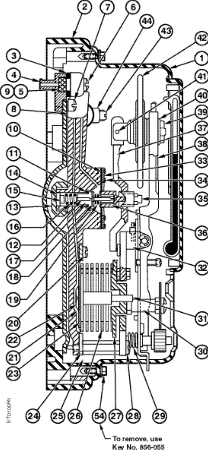
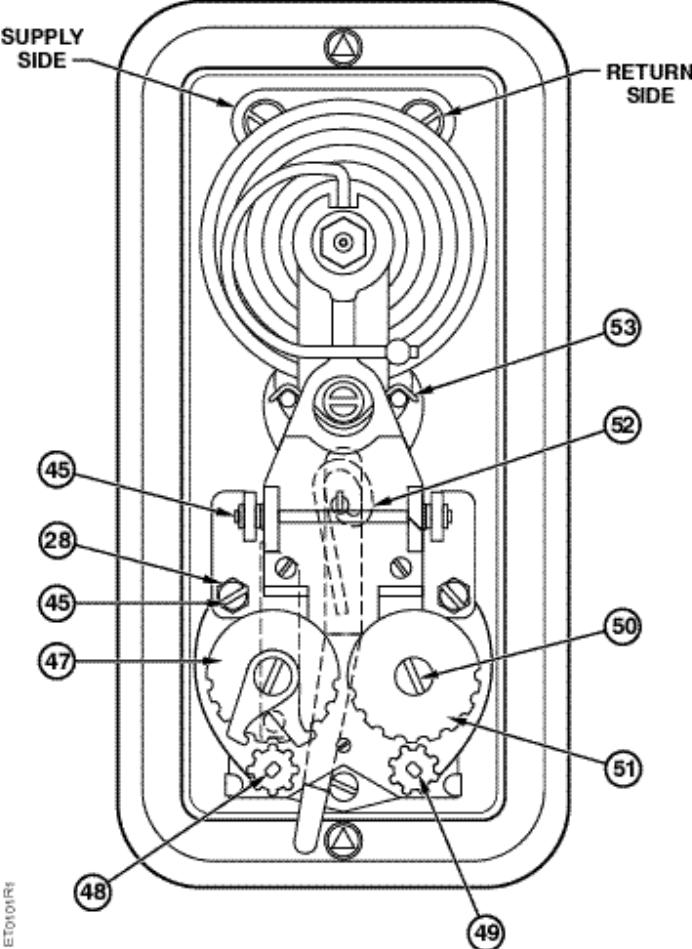
6 Construction Figure 3. Page 6
7 Parts Lists (See Figure 3) Item Description Part No. Kit No.* 1 Cover & Grad Plate Assy. For: Base & Finish Plate Assembly 3 Gasket A, B 4 Terminal Head 5 Filter Disc 6 Screw A 7 Screw 8 Frame 9 Filter (Screen) B 10 Diaphragm B 11 Supply Valve Gasket 12 Supply Valve Body 13 Supply Valve Cap 14 Supply Valve Cap Gasket B 15 Spring Spacer 16 Supply Valve Spring B 17 Exhaust Valve Stem 18 Supply Valve Stem 19 Spring B 20 Screw 21 Diaphragm 22 Diaphragm Plate Screw 23 Diaphragm Plate 24 Diaphragm Ring 25 Spring Retainer Support 26 Spring 27 Spring Retainer 28 Screw Item Description Part No. 29 Spring 30 Dial Support 31 Diaphragm Plate Extension 32 Lever Bearing Plate 33 Diaphragm Ring 34 Screw 35 Valve Adjusting Screw 36 Exhaust Valve Body 37 Control Lever 38 Adjustment Lever Assy. 39 Nut 40 Lockwasher 41 Control Lever Pivot Pin 42 Thermal Assembly 43 Seal Screw 44 Test Valve Body 45 Retainer Ring 46 Spring Retainer Support 47 Dial (Day) 48 Adj. Screw & Pinion (Day) 49 Adj. Screw & Pinion (Night) 50 Dial Retainer Screw 51 Dial (Night) 52 Lever Pivot Pin 53 Friction Spr. (0.031 dia) Music Wire 54 Cover Screw (Supplied with Cover) Not Shown Miscellaneous Parts Kit (For mounting to Powerstar Wall Box) NOTE: Replacement Kit No consists of thermostat less cover and base. * Included in Kit: A B Accessories Part Number Service Parts Part Number D Base for Exposed Tubing Replacement Unit (Chassis only) Adjustment Key Exhaust & Supply Valve Repair Kit Gym Guard Cover Assembly Friction Knob (not in catalog) Concealed Adjust Key Adjust Siemens Building Technologies, Inc. Page 7

8 Dimensions Figure 4. Dimensions. Information in this publication is based on current specifications. The company reserves the right to make changes in specifications and models as design improvements are introduced. Powers is a registered trademark of Product or company names mentioned herein may be the trademarks of their respective owners Building Technologies Division 1000 Deerfield Parkway Buffalo Grove, IL Your feedback is important to us. If you have comments about this document, please send them to sbt_technical.editor.us.sbt@siemens.com Document No P25 Printed in the USA Page 8
RC 195 Receiver-Controller
 Document No. 129-082 RC 195 Receiver-Controller Product Description The POWERS RC 195 Receiver-Controller is a pneumatic instrument that receives one, two or three pneumatic inputs. It produces a pneumatic
Powers Controls RC 195 Single Input Receiver-Controller
 Document No. 155-119P25 RC 195-4 Powers Controls RC 195 Single Input Receiver-Controller Description The RC 195 Single lnput Receiver-Controller is a pneumatic instrument which receives one pneumatic input,
Powers Controls RC 195 Multiple Input Receiver- Controller
 Powers Controls RC 195 Multiple Input Receiver- Controller Document No. 155-036P25 RC 195-1 Description Features Application The RC 195 Multiple lnput Receiver-Controller is a pneumatic instrument which
Discontinued. Powers Controls. Technical Instructions Document No P25 RV Rev. 1, May, RV 201 Pressure Reducing Valves.
 Powers Controls RV 201 Pressure Reducing Valves Description Features Product Numbers Dual Pressure PRV Technical Instructions Document No. 155-049P25 RV 201-1 Single Pressure PRV The RV 201 Pressure Reducing
P-5215 Differential Pressure Transmitter
 P-5215 Differential Pressure Transmitter Pneumatic Control Manual 717.1 Pressure Section Product Bulletin P-5215 Issue Date 0891 Features and Benefits Ultra Sensitive Feedback Circuit - Enhances System
DS06D,G Dial Set Pressure Regulating Valve
 DS06D,G Dial Set Pressure Regulating Valve PRODUCT DATA FEATURES APPLICATION Built-in, factory-calibrated outlet pressure adjustment dial. Noncorroding unitized cartridge contains all working parts and
Model: 43T. Bermad Pressure Relief Valve
 Model: 43T Bermad Pressure Relief Valve Installation Operation Maintenance Manual () Rev.C1_01.08.17 Page 1 of 10 Safety First BERMAD believes that the safety of personnel working with and around our equipment
Float Operated Level Controllers
 CONTENTS Float Operated Level Controllers IM0015 Nov. 2014 PAGE Introduction 1 Scope 1 Description 1 Specification 1 Control Installation 2 INTRODUCTION Side Mount Back Mount Prior to installing, the instructions
Reset Volume Controller 2 Reversing Relay 3 Air Valve Actuator 4 Lower-of-Two-Pressures Relay 4 Diverting Relay 5 Higher-of-Two-Pressures Relay 5
 Item Page Reset Volume Controller 2 Reversing Relay 3 Air Valve Actuator 4 Lower-of-Two-Pressures Relay 4 Diverting Relay 5 Higher-of-Two-Pressures Relay 5 Gradual Switch 6 Electric / Pneumatic (E.P.)
Model: 720-UL INSTALLATION OPERATION MAINTENANCE. Bermad Pressure Reducing Valve IOM. Model: FP -720-UL Sizes: 2"-12" BERMAD. Application Engineering
 Bermad Pressure Reducing Valve Model: 720-UL INSTALLATION OPERATION MAINTENANCE Application Engineering BERMAD 1. Safety First BERMAD believes that the safety of personnel working with and around our equipment
Model 130M Pneumatic Controller
 Instruction MI 017-450 May 1978 Model 130M Pneumatic Controller Installation and Operation Manual Control Unit Controller Model 130M Controller is a pneumatic, shelf-mounted instrument with a separate
CSC-2000 SERIES. Reset Volume Controllers MADE IN U.S.A. DESCRIPTION MODELS SPECIFICATIONS ORDERING
 CSC-2000 SERIES Reset Volume Controllers MADE IN U.S.A. DESCRIPTION The CSC-2000 series are designed for use on VAV terminal units in HVAC systems. These are submaster air velocity controllers whose velocity
EXH. Specifications. Descriptions. Min. working pressure MPa
 Functional explanation Primary pressure flowed from passes through check valve on side, and flows in chamber A and B. Primary pressure also passes through pressure adjustment section and switching valve,
CSC-2000 SERIES. Reset Volume Controllers MADE IN U.S.A. DESCRIPTION MODELS SPECIFICATIONS ORDERING
 CSC-2000 SERIES Reset Volume Controllers MADE IN U.S.A. DESCRIPTION The CSC-2000 series are designed for use on VAV terminal units in HVAC systems. These are submaster air velocity controllers whose velocity
SINORIX Valve Reconditioning
 Document No. 129-097 SINORIX Valve Reconditioning Product Description These instructions explain how to recondition and fill 1-inch through 4-inch SINORIX valves. Product Numbers Verify that the appropriate
DS05C,D,G Dial Set Pressure Regulating Valves
 DS05C,D,G Dial Set Pressure Regulating Valves APPLICATION The Honeywell DS05C,D,G Dial Set Pressure Regulating Valve is a high quality pressure regulating valve that maintains a constant outlet pressure
Components for air preparation and pressure adjustment. OUT port position ( ) connected Rear side. of IN port. Air tank. directly.
 connected Rear side. of IN port. Air tank. directly.") Components preparation and pressure adjustment ABP Overview ABP is a component that enables boosting by s only up to twice primary pressure (.0MPa max.) in combination with using air tank but not using
Components preparation and pressure adjustment ABP Overview ABP is a component that enables boosting by s only up to twice primary pressure (.0MPa max.) in combination with using air tank but not using
3/8" Dr. Air Butterfly Impact Wrench
 8192106 3/8" Dr. Air Butterfly Impact Wrench Owner s Manual Read and understand all instructions before use. Retain this manual for future reference. Specifications Construction: Polished aluminum and
PNEUMATIC PRESSURE CONTROLLERS
 PNEUMATIC PRESSURE CONTROLLERS VARIABLE VOLUME PRESSURE CONTROLLER MODELS: V-1 R AND V-2R The 3D Variable Volume Pressure Controller is available for requirements of 0-1,000 psi and 0-6,000 psi in absolute
TEST SPECIFICATION NYT-909-C
 748 Starbuck Ave, Watertown, NY 13601 Phone: +1-315-786-5200 Engineering Fax: +1-315-786-5673 TEST SPECIFICATION NYT-909-C CODE OF TESTS FOR TESTING "AB" TEST RACK P/N 702546 & 702612 ISSUE NO. 5 1.0 THE
D05 Pressure Regulating Valves
 D05 Pressure Regulating Valves FEATURES PRODUCT DATA Noncorroding unitized cartridge contains all working parts and is easily replaceable. Includes built-in strainer and thermal bypass. Balanced seat construction
RG1200 Service and Repair Manual
 Dive Rite RG 1200 Regulator Service and Repair Manual Page 1 Text and Photography by Pete Nawrocky Copyright ( ) 1999-2000, Lamartek, Inc., dba Dive Rite RG1200 Service and Repair Manual First Stage.........................................
V43 Pressure Actuated Water Regulating Valve
 FANs 125, 121 Product/Technical Bulletin V43 Issue Date 0996 V43 Pressure Actuated Water Regulating Valve The V43 Pressure Actuated Water Regulating Valves are designed to regulate water flow for water-cooled
2 in. 18 Gauge Brad Nailer. User manual
 8504342 2 in. 18 Gauge Brad Nailer User manual Technical Data Capacity....100pcs Nail length... 15-50mm( 5/8-2 ) Fastener size....18gauge (1.25 1.00mm) Operation pressure 70-110PSI(4.8-7.5bar) Air inlet....1/4
CTC 1000 Series One-Pipe, Pneumatic Room Thermostat, Single Temperature
 Thermostats CTC 1000 Series One-Pipe, Pneumatic Room Thermostat, Single Temperature Description The CTC 1000 series room thermostats are for use in HVAC systems for the control of pneumatic valves and
SERVICE MANUAL No. I-0043
 Bettis Canada Ltd. 4112 91A Street Edmonton, Alberta, Canada T6E 5V2 Tel: (403) 450-3600 Fax: (403) 450-1400 SERVICE MANUAL No. I-0043 Edmonton GAS/HYDRAULIC ADDITIONAL COMPONENTS CUSTOMER: P.O.#: W.O.#:
Bermad Pressure Reducing. Model: 42T
 Bermad Pressure Reducing Pilot Operated Pressure Control Valve Model: 42T Installation Operation Maintenance Manual (IOM) REV. 27.7.17 Page 1 of 12 Safety First BERMAD believes that the safety of personnel
Pressure Independent Control Series
 Document No. 155-522 Pressure Independent Control Series Two-Way Cast Iron Flanged Bodies, ANSI 125 and 250 Description Siemens Pressure Independent Control Valves integrate three functions into a single
Pressure Dump Valve Service Kit for Series 3000 Units
 Instruction Sheet Pressure Dump Valve Service Kit for Series 000 Units. Overview The Nordson pressure dump valve is used to relieve hydraulic pressure instantly in Series 00, 400, 500, and 700 applicator
SKP Series SKP25 U.. Pressure Regulating Gas Valve Actuator with Safety Shut-off Function
 SKP Series SKP25 U.. Pressure Regulating Gas Valve Actuator with Safety Shut-off Function Technical Instructions Document No. 155-752 SKP25 U.. Description Only when assembled to Series VG Gas valves SKP25
Series K Air service units G 1/8, G 1/4
 Air service units G /8, G /4 Series FK Filter, G /8 G /4.02 Series RK Pressure regulator, G /8 G /4.04 Series FRK Filter/regulator, G /8 G /4.06 Series OK Lubricator, G /8 G /4.08 Series FROK Two piece
Instruction Manual Updated 7/26/2011 Ver. 2.2
 4-Unit Model MB HTHP Filter Press #171-50-4: 115-Volt #171-51-4: 230-Volt Instruction Manual Updated 7/26/2011 Ver. 2.2 OFI Testing Equipment, Inc. 11302 Steeplecrest Dr. Houston, Texas 77065 U.S.A. Tele:
INSTALLATION INSTRUCTIONS. CVS 67CFR Pressure Reducing Instrument Supply Regulator INTRODUCTION
 INSTALLATION INSTRUCTIONS CVS 67CFR Pressure Reducing Instrument Supply Regulator INTRODUCTION The CVS Controls 67CFR Filter regulator is a pressure reducing supply regulator typically used for pneumatic
accidents which arise due to non-observance of these instructions and the safety information herein. SPECIFICATIONS
 18 GAUGE 1-1/4 INCH BRAD NAILER Model: 7611 CALIFORNIA PROPOSITION 65 WARNING: You can create dust when you cut, sand, drill or grind materials such as wood, paint, metal, concrete, cement, or other masonry.
RS(H)10,15 USER MANUAL. Read the complete manual before installing and using the regulator.
10,15 USER MANUAL. Read the complete manual before installing and using the regulator.") RS(H)10,15 USER MANUAL Read the complete manual before installing and using the regulator. WARNING INCORRECT OR IMPROPER USE OF THIS PRODUCT CAN CAUSE SERIOUS PERSONAL INJURY AND PROPERTY DAMAGE. Due to
RS(H)10,15 USER MANUAL Read the complete manual before installing and using the regulator. WARNING INCORRECT OR IMPROPER USE OF THIS PRODUCT CAN CAUSE SERIOUS PERSONAL INJURY AND PROPERTY DAMAGE. Due to
CUT OFF TOOL MODEL: CAT113
 CUT OFF TOOL MODEL: CAT113 Part No: 3120135 ASSEMBLY & INSTRUCTION MANUAL LS0309 INTRODUCTION Thank you for purchasing this CLARKE product Before attempting to use the product, it is essential that you
Model Series 62 Constant Differential Relay
 Siemens Industry, Inc. INSTALLATION AND SERVICE INSTRUCTION INTRODUCTION Model Series 62 Constant Differential Relay Rev 11 March 2011 Supersedes Rev 10 The Constant Differential Relay maintains a constant
Budget Range Operators Handbook
 Budget Range Operators Handbook BAMBI AIR COMPRESSORS LTD 152 Thimble Mill Lane Heartlands Birmingham B7 5HT United Kingdom Tel: 0121 322 2299 Fax: 0121 322 2297 Email: sales@bambi-air.co.uk www.bambi-air.co.uk
Welker Sampler. Model GSS-1. Installation, Operation, and Maintenance Manual
 Installation, Operation, and Maintenance Manual Welker Sampler Model GSS-1 The information in this manual has been carefully checked for accuracy and is intended to be used as a guide to operations. Correct
Maximum 0.85 MPa pressure setting Long-life, high flow perfect for balancer applications
 Outstanding performance in extremely low pressure and low pressure ranges from 0.003 to. Realizing high performance, energy saving, and compact size. Realize precise pressure control in a pressure range
Pressure Dump Valve Service Kit for Series 2300 Units
 Instruction Sheet Pressure Dump Valve Service Kit for Series 00 Units. Overview The Nordson pressure dump valve is used to relieve hydraulic pressure instantly in Series 00 applicator tanks when the unit
Air service units series K G1/8, G1/4
 Air service units series K Series FK Filter 12.011 Series RK Pressure regulator 12.012 Series FRK Filter/regulator 12.013 Series OK Lubricator 12.014 Series FROK Two piece air service unit 12.015 Series
1650EXLT, ,
 1650EXLT, 96193008901, 2012-10 "CHASSIS, ENGINE & PULLEYS" - 000 00 00-00 W/O DESCRIPTION 1 B&S 21M307-0135-F1 FOR SERVICE & PARTS 1-800-233-3723 1 532 42 92-03 FRAME 1 2 532 15 04-06 BOLT 1 3 532 42 88-67
4150K and 4160K Series Wizard II Pressure Controllers and Transmitters
 Instruction Manual Form 5177 March 1999 4150K and 4160K Series 4150K and 4160K Series Wizard II Pressure Controllers and Transmitters Contents Introduction.............................. 2 Scope of Manual.............................
TWO POST RAM PACKAGE 5 GALLON READ THIS MANUAL CAREFULLY BEFORE INSTALLING, OPERATING OR SERVICING THIS EQUIPMENT.
 OPERATOR S MANUAL TP0411G2XXXXXXXX INCLUDING: OPERATION, INSTALLATION AND MAINTENANCE. RELEASED: 2-15-10 INCLUDE MANUALS: AF0411GXXXXXX-XX-X Two-Ball Pump (97999-1496), 66731-X Follower Assembly (pn REVISED:
Type S301 & S302 Gas Regulators INTRODUCTION INSTALLATION. Scope of Manual. Description. Specifications. Type S301 and S302. Instruction Manual
 Fisher Controls Instruction Manual Type S301 & S302 Gas Regulators October 1981 Form 5180 WARNING Fisher regulators must be installed, operated, and maintained in accordance with federal, state, and local
LRS(H)4 USER MANUAL. Read the complete manual before installing and using the regulator.
4 USER MANUAL. Read the complete manual before installing and using the regulator.") LRS(H)4 USER MANUAL Read the complete manual before installing and using the regulator. WARNING INCORRECT OR IMPROPER USE OF THIS PRODUCT CAN CAUSE SERIOUS PERSONAL INJURY AND PROPERTY DAMAGE. Due to the
LRS(H)4 USER MANUAL Read the complete manual before installing and using the regulator. WARNING INCORRECT OR IMPROPER USE OF THIS PRODUCT CAN CAUSE SERIOUS PERSONAL INJURY AND PROPERTY DAMAGE. Due to the
64 Series Pressure Reducing Regulators
 Instruction Manual Form 1245 64 Series March 2006 64 Series Pressure Reducing Regulators W1943 Figure 1. 64 Series Regulator Introduction Scope of Manual This manual provides instructions for the installation,
Installation and User Manual
 49124589 Revision A August 2015 PacE Flow Controller Installation and User Manual Save These Instructions Table of contents Table of contents..................................................... 2 INSTALLATION............................................................3
Vibration isolation system 1VIS10W. User manual
 Vibration isolation system 1VIS10W User manual Standa 2014 Table of contents 1. General information 3 1.1. Introduction 3 1.1.1. Safety 5 1.2. Location of the table 5 1.3. Air supply requirements 5 2.
P14 Series Pressure Actuated Mechanical Sequencer
 P14 Series Pressure Actuated Mechanical Sequencer Master Catalog 125 Pressure Controls Section P Product Bulletin P14 Issue Date 0996 Application P14 mechanical sequencers have multiple SPDT electric Pennswitches
D05T Compact Design Pressure Regulating Valves
 D05T Compact Design Pressure Regulating Valves FEATURES PRODUCT DATA Non-corroding unitized cartridge contains all working parts and is easily replaceable. Includes built-in strainer and thermal bypass.
TECHNICAL INSTRUCTIONS
 TECHNICAL INSTRUCTIONS Hydroguard Series 410 Valves Model 5 and Model 8 Form TI410-5 v3 DESCRIPTION The Series 410 Hydroguard is a pressure compensating mixer which delivers a predetermined water temperature,
400H HARDMOUNT AIR COMPRESSOR KIT PART NO H HARDMOUNT AIR COMPRESSOR KIT PART NO
 400H HARDMOUNT AIR COMPRESSOR KIT PART NO. 40042 450H HARDMOUNT AIR COMPRESSOR KIT PART NO. 45042 400H 450H IMPORTANT: It is essential that you and any other operator of this product read and understand
GX200 QX2 ENGINE, JPN, VIN# GCAE Page 1 of 34 AIR CLEANER (DUAL)
") GX200 QX2 ENGINE, JPN, VIN# GCAE-1000001 Page 1 of 34 AIR CLEANER (DUAL) GX200 QX2 ENGINE, JPN, VIN# GCAE-1000001 Page 2 of 34 Ref # Part Number Qty Description AIR CLEANER (DUAL) 1 16271-ZE1-000 1 GASKET,
GX200 QX2 ENGINE, JPN, VIN# GCAE-1000001 Page 1 of 34 AIR CLEANER (DUAL) GX200 QX2 ENGINE, JPN, VIN# GCAE-1000001 Page 2 of 34 Ref # Part Number Qty Description AIR CLEANER (DUAL) 1 16271-ZE1-000 1 GASKET,
CRYOGENIC TANK SERVICES - CHART RECORDER MANUAL
 CRYOGENIC TANK SERVICES - CHART RECORDER MANUAL Pressure Chart Recorder / Temperature Chart Recorder / Dual Recorder Portable Mechanical Chart Recorder for the accurate measurement and recording of Pressure
Installation, Operation, and Maintenance Manual
 Installation, Operation, and Maintenance Manual Welker Instrument Supply Pressure System Model WIC The information in this manual has been carefully checked for accuracy and is intended to be used as a
Model 4000 Pressure Controller
 FEATURES Multiple Configurations The 4000 series pressure controller can be configured into either proportional only or proportional plus reset mode with a minimum of parts. Rugged Design Die cast aluminum
Anderson Greenwood Series 93 Positive Pressure POSRV Installation and Maintenance Instructions
 Before installation these instructions must be fully read and understood Installation and maintenance instructions for Series 93 Positive Pressure Pilot Operated Safety Relief Valves (POSRV). The intent
ATV 90 Y-12 YOUTH 2-STROKE RED (A2004ATB2BUSR) Page 1 of 52 A-ARM, FLOOR PANEL, AND BUMPER ASSEMBLY
 Page 1 of 52 A-ARM, FLOOR PANEL, AND BUMPER ASSEMBLY") 2004 ATV 90 Y-12 YOUTH 2-STROKE RED (A2004ATB2BUSR) Page 1 of 52 A-ARM, FLOOR PANEL, AND BUMPER ASSEMBLY 2004 ATV 90 Y-12 YOUTH 2-STROKE RED (A2004ATB2BUSR) Page 2 of 52 A-ARM, FLOOR PANEL, AND BUMPER
2004 ATV 90 Y-12 YOUTH 2-STROKE RED (A2004ATB2BUSR) Page 1 of 52 A-ARM, FLOOR PANEL, AND BUMPER ASSEMBLY 2004 ATV 90 Y-12 YOUTH 2-STROKE RED (A2004ATB2BUSR) Page 2 of 52 A-ARM, FLOOR PANEL, AND BUMPER
Replaces Lesco 300 & 500 Parts
 Replaces Lesco 300 & 500 Parts ItemNo R&R PartNo PartNo Description Req. Qty Price R&R Reels Available, Lifetime Guaranteed 1 R502871 020800 R&R Reel, 9 Blade, Fits 300 1 32,100 1 R502871H R&R Only R&R
Techcon Systems TS1254 Pressure Pot
 Techcon Systems TS1254 Pressure Pot User Guide Copyright OK International, Inc. TABLE OF CONTENT 1. SAFETY. 3 1.1 Intended Use 3 1.2 Safety Precaution 3 2. FEATURES. 5 3. SPECIFICATIONS 4 4. INSTALLATION
ALE-32. Miniature General Purpose Regulators R07, R46 (non-repairable) Air line equipment. Technical data
 Air line equipment. Technical data") ir line equipment Miniature eneral Purpose egulators 7, (non-repairable) 7 Full flow gauge ports Snap action knob locks pressure setting when pushed in Standard relieving models allow reduction of outlet
ir line equipment Miniature eneral Purpose egulators 7, (non-repairable) 7 Full flow gauge ports Snap action knob locks pressure setting when pushed in Standard relieving models allow reduction of outlet
TECHNICAL DATA. Page 1 of 12
 Page 1 of 12 1. DESCRIPTION The Viking Regulating Valve is a direct-acting, single-seated, spring-loaded diaphragm valve. When installed as a pilot regulating valve on a Viking Model H or J Flow Control
4 ANGLE GRINDER MODEL NO: CAT 52 PART
 4 ANGLE GRINDER 4 ANGLE GRINDER MODEL NO: CAT 52 PART No: 3110685 OPERATION & MAINTENANCE INSTRUCTIONS 0807 Fig.1 SPECIFICATIONS Model:...CAG52 Part Number:...3110685 Rated Wheel...Capacity: 4 x 1/4 (type
200 PSI FAST-FILL AIR SOURCE KIT
 200 PSI FAST-FILL AIR SOURCE KIT 55% Duty Compressor on 2.0 Gallon Air Tank PART NO. 20007 IMPORTANT: It is essential that you and any other operator of this product read and understand the contents of
Pressure and/or Temperature Pilot Operated Steam Regulators Series 2000
 Hoffman Specialty Regulators Regulators Pressure and/or Temperature Operated Regulators Series 2000 The Hoffman Specialty Series 2000 consists of main valves, pilot valves, wells and hardware kits. They
TECHNICAL DATA 3 MODEL G-3000 DRY VALVE RISER ASSEMBLY
 Page 1 of 13 1. DESCRIPTION The Viking 3 Model G-3000 Dry Valve Riser Assembly is equipped with a small profile, light weight, pilot operated valve that is used to separate the water supply from the dry
AIR COMPRESSOR OPERATION & MAINTENANCE INSTRUCTIONS MODEL NO: CHAMP 3 PART NO: LS0115
 AIR COMPRESSOR MODEL NO: CHAMP 3 PART NO: 2225222 OPERATION & MAINTENANCE INSTRUCTIONS LS0115 INTRODUCTION Thank you for purchasing this CLARKE Air Compressor. Please read this manual fully before use
MEGR-1912 Instruction Manual
 MEGR-1912 PRESSURE REGULATOR Instruction Manual- Look Inside For: Description Installation Start-Up Maintenance Parts Ordering Parts List Marshall Excelsior Company Marshall, MI 49068 269-789-6700 FAX
P5513. Users Manual. Pneumatic Comparison Test Pump. Test Equipment Depot Washington Street Melrose, MA TestEquipmentDepot.
 Test Equipment Depot - 800.517.8431-99 Washington Street Melrose, MA 02176 TestEquipmentDepot.com P5513 Pneumatic Comparison Test Pump Users Manual PN 3963372 November 2010 2010 Fluke Corporation. All
Index Table. Model 794. Installation, Operating and Maintenance Instructions
 CLOCKWISE MANUAL MAKING INTO CCW TABLE Index Table Model 794 Installation, Operating and Maintenance Instructions Black & Webster Products Division 545 Hupp Ave. P.O. Box 831, Jackson, Michigan 49204 2009
TECHNICAL DATA Q = C. v P S. 2 Model G-2000 Dry valve. Page 1 of 13
 Page 1 of 13 1. Description The Viking 2 Model G-2000 Dry Valve Riser Assembly consists of a small profile, light weight, pilot operated valve that is used to separate the water supply from the dry sprinkler
I T T Pressure Reducing Valve WARNING INSTALLATION, OPERATION, AND MAINTENANCE MANUAL
 INSTALLATION, OPERATION, AND MAINTENANCE MANUAL I-867-4T 867-4T Pressure Reducing Valve HANG THESE INSTRUCTIONS ON THE INSTALLED VALVE FOR FUTURE REFERENCE WARNING Read and understand all instructions
accidents which arise due to non-observance of these instructions and the safety information herein. SPECIFICATIONS
 18 GAUGE 2 INCH BRAD NAILER Model: 7555 CALIFORNIA PROPOSITION 65 WARNING: You can create dust when you cut, sand, drill or grind materials such as wood, paint, metal, concrete, cement, or other masonry.
GT20 String Trimmer UT Page 1 of 16 Accessories
 GT20 String Trimmer UT-26037 Page 1 of 16 Accessories GT20 String Trimmer UT-26037 Page 2 of 16 Accessories Ref # Part Number Qty S/P/F Description 1 PS01443 1 TOOL KIT 2 DG07819 1 /P STRAP 3 G07830 1
VACUUM REGULATORS CONTENTS
 CAD drawing data catalog is available. ACCESSORIES GENERAL CATALOG AIR TREATMENT, AUXILIARY, VACUUM, AND FLUORORESIN PRODUCTS CONTENTS Small Regulators Features 759 Specifications, Order Codes, Flow Rate
450P- RV AUTOMATIC PORTABLE COMPRESSOR EXTREME SERIES
 450P- RV AUTOMATIC PORTABLE COMPRESSOR EXTREME SERIES PART NO. 45053 IMPORTANT: It is essential that you and any other operator of this product read and understand the contents of this manual before installing
PRS(TC)4,8 USER MANUAL. Read the complete manual before installing and using the regulator.
4,8 USER MANUAL. Read the complete manual before installing and using the regulator.") PRS(TC)4,8 USER MANUAL Read the complete manual before installing and using the regulator. WARNING INCORRECT OR IMPROPER USE OF THIS PRODUCT CAN CAUSE SERIOUS PERSONAL INJURY AND PROPERTY DAMAGE. Due to
PRS(TC)4,8 USER MANUAL Read the complete manual before installing and using the regulator. WARNING INCORRECT OR IMPROPER USE OF THIS PRODUCT CAN CAUSE SERIOUS PERSONAL INJURY AND PROPERTY DAMAGE. Due to
RARS5000 AIR BODY SAW OWNER S OPERATING MANUAL
 RARS5000 AIR BODY SAW OWNER S OPERATING MANUAL DESCRIPTION 1. No mar 2. No mar tip 3. Housing grip 4. Trigger 5. Air inlet 6. Air inlet plug 7. Plastic board Important! It is essential that you read the
Part No (Low Changeover) Part No (High Changeover) Part No (High Changeover)
 Part No (High Changeover) Part No (High Changeover)") ELX-S TM UNIT 60% 665020 (Low Changeover) 305274 (High Changeover) 305305 (High Changeover) IMPORTANT: This catalog is published as an aid in identifying the detail parts that make up this complete device.
ELX-S TM UNIT 60% 665020 (Low Changeover) 305274 (High Changeover) 305305 (High Changeover) IMPORTANT: This catalog is published as an aid in identifying the detail parts that make up this complete device.
Air Operated Hydraulic Pumping Systems to 50,000 psi
 High Pressure Equipment Air Operated Hydraulic Pumping Systems to 50,000 psi PS-10: 10,000 psi PS-20: 20,000 psi PS-30: 30,000 psi PS-40: 40,000 psi PS-50: 50,000 psi PS-90: 90,000 psi High Pressure air
MODEL NUMBER: PSI AIR SOURCE KIT 200 PSI Compressor on 2.0 Gallon 200 PSI Air Tank
 IMPORTANT SAFETY INSTRUCTIONS CAUTION - To reduce risk of electrical shock or Electrocution: MODEL NUMBER: 20008 200 PSI AIR SOURCE KIT 200 PSI Compressor on 2.0 Gallon 200 PSI Air Tank IMPORTANT: It is
TECHNICAL DATA. Q = C v P S
 Page 1 of 13 1. DESCRIPTION The Viking 6 Model G-6000 Dry Valve Riser Assembly consists of a small profile, light weight, pilot operated valve that is used to separate the water supply from the dry sprinkler
TWO POST RAM PACKAGE 55 GALLON
 OPERATOR S MANUAL TP1265S5XXXXXXXX INCLUDING: OPERATION, INSTALLATION AND MAINTENANCE. INCLUDE MANUALS: AF1265SXXXXXX Extrusion Pump (97999-1528), RM552X-XXX-XX Two Post Lift / Ram (pn 97999-1445), & S-636
7130 Lancer Rear Drive Magnetic Commercial Indoor Cycling Bike
 7130 Lancer Rear Drive Magnetic Commercial Indoor Cycling Bike Owner s Manual Made in Taiwan INDEX IMPORTANT SAFETY INFORMATION... 1 EXPLODED DRAWING... 2 PARTS LIST... 3 ASSEMBLY INSTRUCTION... 4-9 USER
Operating Instructions Model and Hydrostatic Test Pump
 Operating Instructions Model 39300 and 39301 Hydrostatic Test Pump Dimension Weight Pump Style Capacity Pressure Motor Lubrication Control Gauge Inlet Connection Outlet Connection Discharge Hose Hose Ends
55DEHD 07 (63S5) 1F63S-561E1
 1F63S-561E1") 55DEHD 07 () 1F63S-561E1 ( ) 55DEHD PARTS CATALOGUE 2006 by Yamaha Motor Co., Ltd. 1st edition, November 2006 All rights reserved. Any reprinting or unauthorized use without the written permission of Yamaha
55DEHD 07 () 1F63S-561E1 ( ) 55DEHD PARTS CATALOGUE 2006 by Yamaha Motor Co., Ltd. 1st edition, November 2006 All rights reserved. Any reprinting or unauthorized use without the written permission of Yamaha
OPERATING AND MAINTENANCE MANUAL
 Series 4300 Engineered Performance TABLE OF CONTENTS 0 INTRODUCTION 1 1 Scope 1 2 Description 1 3 Specifications 1 0 INSTALLATION 1 1 Mounting 1 2 Piping 1 1 Connecting Process Pressure 2 2 Vent Connections
Beamex PG PRESSURE GENERATORS. Beamex PGM PGV PGC PGHH PGPH PGL
 Beamex PG PRESSURE GENERATORS 97 Beamex PGM PGV PGC PGHH PGPH PGL Beamex PG pressure generators are portable hand-operated pressure generators and ultimate field calibration pumps 98 Calibration pumps
36E DSI, HSI & Proven Pilot Two-Stage Combination Gas Valve INSTALLATION INSTRUCTIONS
 INLET PRESS TAP WTE-RODGERS 36E96-314 DSI, HSI & Proven Pilot Two-Stage Combination Gas Valve INSTALLATION INSTRUCTIONS Operator: Save these instructions for future use! FAILURE TO READ AND FOLLOW ALL
Suggested Installation & Operating Instructions for Sidewinder Pumps
 Model 164 C P.O. Box 80769 Lafayette, LA 70598-0769 (337) 235-9838 FAX (337) 235-9852 www.sidewinderpumps.com Pneumatic Powered - Plunger Pump Suggested Installation & Operating Instructions for Sidewinder
MODEL NUMBER: M20005 AIR SOURCE KIT. 30% Duty Compressor on. 2.0 Gallon Air Tank SAVE THIS MANUAL FOR FUTURE REFERENCE
 MODEL NUMBER: M20005 AIR SOURCE KIT 30% Duty Compressor on 2.0 Gallon Air Tank SAVE THIS MANUAL FOR FUTURE REFERENCE USER MANUAL IMPORTANT SAFETY INSTRUCTIONS CAUTION - To reduce risk of electrical shock
2.5 & 5.0 GALLON PRESSURE TANKS
 2.5 & 5.0 GALLON PRESSURE TANKS Includes: MODEL 7025 MODEL 7026 MODEL 7027 MODEL 7028 2.5 Gallon Single Regulation (NON A.S.M.E.) 2.5 Gallon Dual Regulation (NON A.S.M.E.) 5.0 Gallon Single Regulation
accidents which arise due to non-observance of these instructions and the safety information herein.
 3 GALLON PANCAKE COMPRESSOR Model: 50959 CALIFORNIA PROPOSITION 65 WARNING: You can create dust when you cut, sand, drill or grind materials such as wood, paint, metal, concrete, cement, or other masonry.
TECHNICAL DATA. Pressure Regulation 531a. April 24, 2009
 April 24, 29 Pressure Regulation 531a 1. DESCRIPTION The Viking Regulating Valve is a direct-acting, single-seated, spring-loaded diaphragm valve. When installed as a pilot regulating valve on a Viking
WW-730. Pressure Sustaining/Relief Control Valve
 WW-730 Pressure Sustaining/Relief Control Valve Installation Operation & Maintenance Page 1 of 6 1. DESCRIPTION The Model 730 Pressure Relief / Sustaining Valve is an automatic control valve designed to
REPAIR PART NUMBER NUMBER DESCRIPTION 0137 ELE 0136 ELE 12 VOLT SOLENOID
 PART REPAIR PART NUMBER NUMBER DESCRIPTION 0137 ELE 0136 ELE 12 VOLT SOLENOID 0203 WHL 0250 WHL WHEEL HUB 0251 WHL AXLE 0252 WHL DUST CAPS 0253 WHL TIRE - 210 SP 0204 WHL 0211 WHL TIRE & WHEEL - SP 0250
Installation and operating manual. Pneumatic control station LK product no: PCS 1-10
 LK product no: PCS 1-10 Article no: 74503 Revision:8 Article no: 74503 Revision: 8 2 (23) Contents 1. General information... 5 2. Safety precautions... 5 2.1 Significance of symbols... 5 2.2 Explanatory
200 PSI HIGH-FLOW AIR SOURCE KIT
 200 PSI HIGH-FLOW AIR SOURCE KIT 50% Duty Compressor on 2.0 Gallon Air Tank PART NO. 20008 IMPORTANT: It is essential that you and any other operator of this product read and understand the contents of