Karl Suss MA6 Mask Aligner SOP
|
|
|
- Clementine Porter
- 6 years ago
- Views:
Transcription
1 Page 1 of 11 Karl Suss MA6 Mask Aligner SOP Safety UV Exposure: The high energy light produced by the high pressure Mercury Xenon lamp can cause eye damage and skin burns. Be sure that the light guards around the exposure area are not removed, and that the high pressure lamp and exposure path are enclosed. Do not looking directly at the mask during exposure. Ozone: The high-pressure lamp produces ozone, which can result in pneumonia-like symptoms. The effects are cumulative. The lamp may only be on when the HEPA air flow is on. Lamp Explosion: If you suspect that the UV Lamp has exploded, evacuate the room immediately and notify UFNF Staff. High Power: The MA6 mask aligner uses ignition voltages of 30kV and operating voltages of 180V, with currents of 5 to 30amps. Ensure that the power line is disconnected before any system maintenance. Moving Components The User should be aware at all times of the moving components associated with this tool. For instance, the topside microscope assembly moves up and down, and does present a potential hazard. The User must exert caution at all times such that a limb, finger, or article of clothing does not become trapped or entangled (or worse, violently detached) when components of the machine are in motion. Description The Karl Suss MA-6 Contact Aligner system can perform precision maskto-wafer (sample) 1:1 contact printing in four modes; hard contact, soft contact, vacuum and proximity. It can accommodate exposure of irregularly shaped substrates and standard wafers to 6. Features: Contact 1:1 aligner. DUV and IR capability Approximate Exposure Intensity: 8 mw/cm2@365 nm, 5 mw/cm2@405 nm Constant exposure intensity controller Two mask holder sizes are available, 4" and 5". Wafer size is 4" and pieces. Maximum wafer thickness 4.3mm Split field microscope for top-side viewing/alignment. resolution = down to.8um in vacuum contact 400nm
2 Page 2 of Power on the Constant Intensity Controller (CIC) 1.1 Check if the CP, CH1 or CH2 buttons on the CIC are illuminated green. If any one button is on then the lamp is on and you may proceed to step 3.0. If the lamp is not on, proceed with step Switch ON power of the Constant Intensity Controller (CIC) located under the main system. The software version is shown on the display. The CIC performs a self calibration test and displays ready. Press CP (constant power) key. Display shows wait, followed by Start. Press the START key. This will ignite the exposure lamp. LED LAMP LIFE/POWER is flashing until lamp warming up is finished. ATTENTION- Nitrogen failure for longer than 5 minutes will turn off the exposure lamp! 2.0 Power up the machine 2.1 Toggle clockwise the POWER SWITCH ELECTRONIC on the front panel control clockwise to ON position and release. Machine initializes. And example for the display message is: 2.2 Press the flashing LOAD key on the keyboard to initialize the system. 3.0 Calculate Your Dose 3.1 Prior to loading your mask, press CH1 on the CIC controller (use CH2 if exposing 405nm photoresist). 3.2 Depress the lamp check button on aligner and record the power value displayed on the CIC display. This is the power output of the lamp at 365nm in Watts/cm To calculate dose, divide the desired dose by the power displayed on the RED LED readout. This is your exposure time in seconds. Example: 140mj / 10Watts = 14 seconds. 4.0 Load Mask 4.1 Warning: Watch out for the microscope movement! 4.2 Start mask loading sequence - CHANGE MASK key. NOTE: If the change lamp key is already blinking, press enter and change mask alternately to get the system out of the last mask change sequence. This may be needed when the last user does not complete the mask sequence. Take out the mask holder, flip it 180º and put it on the tray to the left. If a mask is loaded, press ENTER to toggle the mask vacuum off, retract the mechanical mask clamp by pushing down on the leaf spring until it stops in the detent and remove the mask. 4.3 Place the mask chrome oxide up (DARK SIDE UP, MIRROR FINISH SIDE DOWN, see pic below) onto the mask holder against the stop pins

3 Page 3 of 11 to the left and top of the mask. Toggle the mask vacuum on by pressing the ENTER key. Activate the mechanical mask clamp by pressing on the leaf spring until it contacts the edge of the mask. 4.4 Flip the mask holder over and slide it into the machine. Lock the mask holder slide by pressing CHANGE MASK key again. 5.0 Pre Exposure Operation 5.1 Verify that the CH1 button is illuminated in the Lamp Power (CIC) unit. If not depress CH1. This enables automatic exposure dose compensation. 5.2 Move all the stage micrometers to the center position. For the X axis (right side micrometer) the center is the 8mm position and for the Y micrometer (left side) the center is 8mm. Theta micrometer shall be adjusted so that the white line on the theta position indicator is parallel with the front of the stage. 5.3 Edit parameters - Press EDIT PARAMETER and use the Y keys to scroll through and change all necessary values and confirm by pressing EDIT PARAMETER key again. The following list shows each parameter Exp Time- Determined by formula (dose = mw/cm² x time) Note: For S1813 and AZ9260 resists, use the power reading at 365nm CH1. With no mask loaded, press lamp test to check power reading. Set lamp power supply to CH1. Note: Multiple exposures with delays between exposures are possible. See the supplemental information section below.
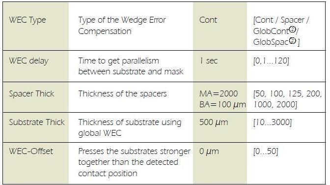
4 Page 4 of Al Gap um sets the gap between the sample and the mask during alignment. setting this parameter too low may cause the sample to touch the mask during alignment WEC Offset WEC Type- cont Exp Type- Hard, Vac, Low Vac, Flood, Proximity. See the following explanation of each mode. If in doubt, contact Staff for instructions. As general rules of thumb.for masks with minimum feature sizes >4um, standard positive photoresist and flat substrates, use Hard Contact mode. For masks with feature sizes <4um use Vac Mode is best (always consult with Staff to use this mode). Hard contact Mode- The WEC unit physically presses the sample against the mask via springs and then locks this position with pneumatic brakes. The wafer then moves down in the Z axis to the alignment gap set in parameter setting. Alignment is performed by the user. During exposure, the wafer moves into contact with the mask. The vacuum securing the wafer to the holder switches to N2 pressure which presses the wafer into further contact with the chrome mask. Soft Contact Mode- Same as Hard Contact mode but without N2 pressure on the back of the wafer. Vacuum Contact Mode- Explanation: This mode provides the highest resolution but only works for whole 4 wafers, 2 wafers using the smaller sample chuck, or quartered 4 wafers using the smaller chuck. The outer orange rubber seal expands to create a seal with the mask surface and vacuum is pulled to remove air while contact is made between the 4 wafer and mask. The rubber seal pressure is adjustable by the VACUUM SEAL regulator. This chamber is evacuated in steps. Pre vacuum gently pulls vacuum into that mini
5 Page 5 of 11 chamber to enable a smooth contact between mask and wafer. Furthermore it prevents gas bubbles to be trapped between both. Full vacuum will be applied with the next step. The wafer will be brought to the closest contact position. The vacuum securing the wafer on the chuck is replaced by nitrogen. In this mode the best contact between mask and wafer is achieved. After the exposure nitrogen will be purged into the mini chamber to break the vacuum. All the parameter could be set using the EDIT PARAMETER key. The settings for this mode are as follows: 1. VACUUM SEAL SETTING -If the vacuum seal pressure is too high it will actually cause the sample to push away from the mask during the vacuum sequence. If this occurs, you will hear a quiet pop sound. It normally means you have the vacuum seal pressure too high. If you set the pressure too low, the vacuum bladder will not expand and the vacuum chamber will not be created. This is evident if you hear an air sound from between the mask and sample during the vacuum sequence. THE BEST SETPOINT FOR VACUUM SEAL IS APPROXIMATELY 0.1 BAR. Start with this setting and adjust it only if you hear a problem during vacuum sequence. A pop noise indicates the pressure is too high, or you hear leaking air sounds (without a pop noise) the air pressure is too low. 2. WEC Pressure Setting Normally 0.5 bar (center of the pressure gauge works well). 3. Low Vacuum Time Setting (edited in parameters) A long low pressure evacuation works best. Set this time for 30 seconds. 4. Vacuum Time Setting (edited in parameters) 5 seconds is enough. Testing Vacuum Contact Mode Operation: The best way to test this mode is by using the Alignment Check button. When the sample is aligned and ready for exposure, pressing this button will bring the wafer into contact with the mask and the Vacuum sequence will run. If the result is good, you can then just press the Exposure button. Low vacuum contact-
6 Page 6 of 11 This mode is similar to vacuum contact with one difference: The vacuum level in the wafer chamber can be adjusted by the LOW VACUUM ADJUSTMENT regulator (205). So the high resolution level of the vacuum contact exposure can be combined with a minimum mechanical stress for wafer and mask. Set an appropriate vacuum with the vacuum chamber regulator (205) and test the result using the ALIGNMENT CHECK key. Flood Expose- It is possible to exposure the whole wafer without a mask. After this mode is selected, the exposure can be started from the initial state by pressing the EXPOSURE key (316). The exposure takes place as long as the exposure time was set independent if a mask(and mask holder) is loaded or not. Proximity Exposure Mode- system does not have this option do not use it Additional parameter information for each mode show in the table below

7 Page 7 of sec. 5 sec
8 Page 8 of Load wafer 6.1 Press the LOAD key. The machine instructs: pull slide and load substrate onto chuck. Pull out the transport slide completely. Insert the proper chuck and place the wafer against the pre-alignment pins. Confirm with ENTER key. Now the wafer is held by vacuum 6.2 Set the X and Y stage micrometers to center position per the label under the micrometer. Set the Theta micrometer so that the rotation indicator line is horizontal and visable. 6.3 The machine instructs: move slide into machine and confirm with ENTER. Watch out for the microscope movement! WEC starts automatically after the last action is completed. The wafer is adjusted parallel to the mask. If the microscope is not lowered automatically press F1 key, confirm with ENTER. 7.0 Alignment 7.1 For a first level print, no alignment is needed and you can continue to section The TSA-microscope image on the monitor is enabled by turning the SPLITFIELD switch to LEFT. Make sure the BSA MICROSCOPE key LED is off. It should stay off as this system has no BSA. 7.3 Turn ILLUMINATION switch to TSA and select the light intensity with the potentiometer underneath this switch. Separate intensity selection for the left/right objective is possible with the aperture located at the left/right microscope front. 7.4 Coarse focus is possible by using the large TSA Z-MOVEMENT knob behind the TSA-microscope. Make sure the TOP/BOTTOM key LED is on and adjust the fine focus separately using the TOP SUBSTRATE LEFT/RIGHT regulators. 7.5 Move the left and right microscopes (separately) to the mask alignment marks using the OBJECTIVE X-SEPARATION knobs (metal knobs to the sides of the microscopes). 7.6 Use the GRAB IMAGE key (option) to superimpose the mask alignment mark image on the monitor with the substrate live image. Here s how. First keystroke grabs the present image and then moves the objectives to the substrate focal plane. The TOP/BOTTOM key LED goes off. The motor control of the microscope manipulator is disabled at this time to prevent you from changing the microscope image reference. Second

9 Page 9 of 11 keystroke deletes the stored image and enables the manipulator again. 7.7 Adjust the left/right microscope image fine focus with the BOTTOM SUBSTRATE LEFT/RIGHT regulator. 7.8 Caution: If mask and wafer are in contact (CONTACT INDICATOR LIGHT ON), don t align the wafer! 7.9 Use the micrometer screws of the alignment stage for STG-X-Y-Θ- MOVEMENT. You may use the SEP up and down keys to change the alignment gap during alignment if needed Alignment check- Press the Alignment Check key and the sample will move the sample into the full contact position. If Vacuum Mode is being used, vacuum sequence will run. If satisfied with the alignment, press the expose button. If more alignment is needed press the button again and the sample will move back to alignment position. 8.0 Exposure 8.1. Pressing the exposure key will move the wafer into exposure position (if not already there via the alignment check button and exposure takes place VERY IMPORTANT----- Return the sample Theta position micrometer to the center of travel so that the position indicator white line is visible as shown below. The sample may not unload is it is too far in either direction Unload the sample Press the CHANGE MASK key when done and the mask holder will be
10 Page 10 of 11 released. Pull the mask holder out, flip it by 180º and store it on the tray to your left. Press ENTER to switch the mask vacuum off. Retract the mechanical clamping and remove the mask. Supplemental Information Exposure Programs The selection of the correct exposure method for your particular application is critical. See the following for details of each mode. The type of exposure program is selectable with the SELECT PROGRAM key. After this selection it is possible to edit all corresponding parameters by pressing the EDIT PARAMETER key. Proximity exposure Our system does not have the proximity option Soft contact exposure Mask and wafer are brought in contact. The structural resolution is better than in proximity exposure. The vacuum securing the wafer onto the chuck is maintained during exposure. The only force to press the wafer against the mask is the force applied during WEC. Hard contact exposure This is similar to soft contact mode. After the wafer has moved into contact, the vacuum underneath the wafer is switched off and nitrogen is purged under the wafer to allow close contact between wafer and mask. Vacuum contact exposure This mode performs the highest resolution levels. After the WEC and alignment the wafer is brought into contact with the mask. The rubber seal of a vacuum chuck is creating a mini chamber between mask and wafer. The rubber seal pressure is adjustable by the VACUUM SEAL regulator. This chamber is evacuated in steps. Pre vacuum gently pulls vacuum into that mini chamber to enable a smooth contact between mask and wafer i.e. it prevents gas bubbles to be trapped. Full vacuum will be applied with the next step. The wafer will be brought to the closest contact position. The vacuum securing the wafer on the chuck is replaced by nitrogen. In this mode the best contact between mask and wafer is achieved. After exposure, nitrogen will be purged into the mini chamber to break the vacuum. The larger the wafer the longer the vacuum and purge times. For best results start a test with long times and reduce them gradually. All the parameters can be set using the EDIT PARAMETER key.
11 Page 11 of 11 Low vacuum contact exposure This mode is similar to vacuum contact with one difference: the vacuum level in the wafer chamber can be adjusted by the LOW VACUUM ADJUSTMENT regulator. So the high resolution level of the vacuum contact exposure can be combined with a minimum mechanical stress for wafer and mask. Set an appropriate vacuum with the vacuum chamber regulator and test the result using the ALIGNMENT CHECK key. Flood exposure It is possible to expose the whole wafer without a mask. After this mode is selected, the exposure can be started from the initial state by pressing the EXPOSURE key. The exposure takes place as long as the exposure time was set independent if a mask (and mask holder) is loaded or not. Multiple exposure For special applications the numerical value for the overall exposure time can be segmented into equal exposure intervals alternating with wait time intervals in which the wafer is not exposed. One exposure time and one wait time is named as one exposure cycle. To perform Multiple Exposure, proceed as follows: 1. Select the corresponding exposure program by the SELECT PROGRAM key. 2. Press the MULTIPLE EXPOSURE key Press the EDIT PARAMETER key Edit the parameter for the exposure program. Edit the numerical value of the corresponding parameters wait time and cycles. 3. Press the flashing EDIT PARAMETER key to finish editing and start alignment followed by the multiple exposure process. Wedge error compensation During this procedure the top side of the wafer will be set parallel to the bottom side of the mask i.e. sets the entire wafer surface on the (as close as possible with this method) same focal plane. Set the WEC type using the EDIT PARAMETER key. Two methods are standard: Contact mode: For the exact parallel setting the wafer will be moved against the mask.
SOP for Karl Suss MJB3 #1 Mask Aligner
 SOP for Karl Suss MJB3 #1 Mask Aligner Rev. 5 (30/11/2016) Safety UV Exposure: The high-energy light produced by the high-pressure Mercury Xenon lamp can cause eye damage and skin burns. Be sure that the
Usage Policies Notebook for Karl Suss MA6 Mid / Deep UV Mask Aligner
 Usage Policies Notebook for Karl Suss MA6 Mid / Deep UV Mask Aligner Revision date September 2014 2 Emergency Plan for Karl Suss MA6 Aligner Standard Operating Procedures for Emergencies Contact information
Standard Operating Manual
 Standard Operating Manual Karl Suss MA6 Mask Aligner Version 1.1 Page 1 of 24 Contents 1. Picture and Location 2. Process Capabilities 2.1 Cleanliness Standard 2.2 Substrate Size 2.3 Photo Mask Size 2.4
Equipment Standard Operating Procedure Greg Allion and Kimberly Appel
 Date Created: May 3, 2004 Date Modified: June 1, 2005 MA6/BA6 Mask Aligner Equipment Standard Operating Procedure Greg Allion and Kimberly Appel 1. Purpose 1.1. Photolithography involves transferring a
Karl Suss MJB4 Mask Aligner
 Karl Suss MJB4 Mask Aligner Tool Manager: Yong Sun ( yongs@princeton.edu; Office 8-8234; Cell 609-917-5076 ) Backup: George Watson ( gwatson@princeton.edu; Office 8-4626; Cell 732-996-2713 ) ******************************************************************************
Warnings: Notes: Revised: October 5, 2015
 Karl Suss MA6 Mask Aligner Standard Operating Procedure Faculty Supervisor: Prof. Robert White, Mechanical Engineering (x72210) Safety Office: Peter Nowak x73246 (Just dial this directly on any campus
MJB4 Mask Aligner Operating Procedure. Effective Date: 07/12/2012 Author(s): Jiong Hua Phone:
: Jiong Hua Phone:") MJB4 Mask Aligner Operating Procedure Effective Date: 07/12/2012 Author(s): Jiong Hua Phone: 402-472-3773 Email: jhua2@unl.edu 1 1 Introduction 1.1 Key Words Karl Suss MJB4 Mask Aligner, Optical Lithography,
MJB4 Mask Aligner Operating Procedure Effective Date: 07/12/2012 Author(s): Jiong Hua Phone: 402-472-3773 Email: jhua2@unl.edu 1 1 Introduction 1.1 Key Words Karl Suss MJB4 Mask Aligner, Optical Lithography,
University of Minnesota Nano Fabrication Center
 Equipment name: Karl Suss Mask Aligners Badger name: MA6-P Revision number: 0 Model: MA6 Revisionist: Paul Kimani Location: Bay 4 PAN Date: September 17, 2015 1. Introduction The Karl Suss MA6-PAN is a
University of Minnesota Nano Fabrication Center
 Equipment name: Karl Suss Mask Aligners Badger name: MA6 & Maba6 Revision number: 4 Models: Revisionist: Paul Kimani Location: Bay 2 Date: April 25, 2013 1. Introduction The Karl Suss MA6 and MABA6 are
KARL SUSS MJB3 MASK ALIGNER STANDARD OPERATING PROCEDURE
 KARL SUSS MJB3 MASK ALIGNER STANDARD OPERATING PROCEDURE Purpose of this Instrument: This instrument is for patterning photosensitive polymers with UV light. Location: White Hall 410 Cleanroom Primary
KARL SUSS MJB3 UV400 Mask Aligner Standard Operating Procedure
 KARL SUSS MJB3 UV400 Mask Aligner Standard Operating Procedure Version: 1.0 February 2014 UNIVERSITY OF TEXAS AT ARLINGTON Nanotechnology Research Center (NRC) 1 TABLE OF CONTENTS 1 Introduction 3 1.1
MJB-3 Mask Aligner Property of TAU MNCF August 2012
 MJB-3 Mask Aligner I. Power Up Sequence 1 LOG IN. Turn on Nitrogen & compressed air lines on the back wall. 2 Turn on the vacuum pump. 3 Flip the COMPRESSED AIR toggle on (up) Compressed air is used to
Standard Operating Manual
 Standard Operating Manual AB-M Mask Aligner Version 1.1 Page 1 of 18 Contents 1. Picture and Location 2. Process Capabilities 2.1 Cleanliness Standard 2.2 Wafer Chuck Selection 2.3 Mask Holder Selection
Warnings: Notes: Revised: January 8,
 OAI Model 204IR Mask Aligner Standard Operating Procedure Faculty Supervisor: Prof. Robert White, Mechanical Engineering (x72210) Safety Office: Peter Nowak x73246 (Just dial this directly on any campus
COBILT CA-800 Mask Aligner Equipment Operation
 COBILT CA-800 Mask Aligner Equipment Operation For the Micro-Electronics Laboratory At University of Notre Dame Department of Electrical Engineering This user manual is not be removed from room 247A. This
Quintel Mask Aligner
 Quintel Mask Aligner (quintel) 1.0 1.0 Title Quintel Q4000 Mask Aligner 2.0 2.0 Purpose The Quintel Q4000 MA (Mask Aligner) is a top and bottom side contact lithography printer with the video-view split
Approved by Principal Investigator Date: Approved by Super User: Date:
 Approved by Principal Investigator Date: Approved by Super User: Date: Standard Operating Procedure BNC OAI 200 Lithographic Mask Aligner (Aligner 3) Version 2011 June 2 I. Purpose This Standard Operating
OAI Model 200 Tabletop Mask Aligner Portland State University
 OAI Model 200 Tabletop Mask Aligner Portland State University WARNING: This machine exposes users to ultraviolet radiation. Do not touch the lens underneath the lamp hood as it may damage the machine and
Karl Suss Contact Aligner Operation
 Karl Suss Contact Aligner Operation Roger Robbins 6/31/2008 2 nd ed. 3/12/2009 The University of Texas at Dallas Erik Jonsson Engineering School of Engineering TITLE: Karl Suss Contact Aligner Operation
ABM MASK ALIGNERS. NanoFab 26 March 2009 A Micro Machining & Nanofabrication Facility
 ABM MASK ALIGNERS LOCATION: Optical Lithography PRIMARY TRAINER: Stephanie Bozic (2-6724, sbozic@ualberta.ca) SECONDARY TRAINER: Jolene Chorzempa (2-4823, jolenec@ualberta.ca) 1. OVERVIEW The ABM Mask
Approved by Principal Investigator Date: Approved by Super User: Date:
 Approved by Principal Investigator Date: Approved by Super User: Date: Standard Operating Procedure BNC OAI Lithographic Mask Aligner (Aligner 2) Version 2008 October 31 I. Purpose This Standard Operating
Operation of the mask aligner MJB-55
 John Paul Adrian Glaubitz Operation of the mask aligner MJB-55 Department of Physics Faculty of Mathematics and Natural Sciences University of Oslo 1 Introduction The mask aligner is an essential tool
Standard Operating Manual
 Standard Operating Manual Allwin21 AW610 RTP Page 1 of 18 Contents 1 Picture and Location 2 Process Capabilities 2.1 Cleanliness Standard 2.2 Recipes 2.3 Performance of Allwin21 AW610 RTP 3 Contact List
O P E R ATING INSTRUCTIONS FOR MODEL SPR-45 Automatic Screen and Stencil Printer
 O P E R ATING INSTRUCTIONS FOR MODEL SPR-45 Automatic Screen and Stencil Printer TABLE OF CONTENTS I. SPECIFICATIONS...3. II. SAFETY INSTRUCTIONS...4. III. INSTALLATION...5. IV. SET-UP...6. V. SYSTEM OPERATION...9.
Unaxis ICP/RIE SOP Revision 8 09/30/16 Page 1 of 5. NRF Unaxis ICP/RIE Etch SOP
 Page 1 of 5 NRF Unaxis ICP/RIE Etch SOP Unaxis Shuttlelock Reactive Ion Etcher with Inductively Coupled Plasma Module. Etch Capabilities: SiO2, Si3N4, Al, dielectrics and other commonly used materials.
March CS-1701F Reactive Ion Etcher
 March CS-1701F Reactive Ion Etcher Standard Operating Procedure Faculty Supervisor: Prof. Robert White, Mechanical Engineering (x72210) Safety Office: Peter Nowak x73246 (Just dial this directly on any
Standard Operating Procedure. For. PVD E-Beam
 P a g e 1 Standard Operating Procedure For PVD E-Beam P a g e 2 Introduction The PVD Electron-Beam Evaporator (E-Beam) thin film deposition machine uses a magnetically guided and collimated stream of electrons
SSI Solaris 150 RTA Revision /27/2016 Page 1 of 9. SSI Solaris 150 RTA
 Page 1 of 9 SSI Solaris 150 RTA The Solaris 150 RTA is a rapid thermal annealing system capable of handling sample sizes up to 100mm (4 diameter) or smaller. The system can anneal in N 2 and Forming gas
Operation of the contact mask aligner Canon PPC 210 Projection Print Camera
 Operation of the contact mask aligner Canon PPC 210 Projection Print Camera Start-up Procedure: 1. Start the grey pump in the service corridor behind the aligner 2. Open the valve for the Nitrogen gas
Nanofabrication Facility: PECVD SOP Rev. 00, April 24
 Author: Charlie Yao & Mario Beaudoin Email: charlieyao@gmail.com; Beaudoin@physics.ubc.ca Phone: 604-822-1853(MB). Purpose This document outlines the standard operation for the Trion Plasma Enhanced Chemical
BASIC Z-STACK AND TIME SERIES SCAN ON THE ZEISS LIGHTSHEET Z. 1
 BASIC Z-STACK AND TIME SERIES SCAN ON THE ZEISS LIGHTSHEET Z. 1 The front door of the main body of the instrument may be open when you arrive. Take the sample chamber and slide it into position with the
Misaligned Folds Paper Feed Problems Double Feeds Won t Feed FLYER Won t Run iii
 Operator s Manual Table of Contents Operator Safety... 1 Introduction... 2 Unpacking and Setup... 3 Unpacking... 3 Setup... 4 FLYER Overview... 5 FLYER Diagram... 5 Capabilities... 5 Control Panel... 6
5.1.3 Mechanical Hazards Drive assemblies have sufficient power to cause injury. Keep hands, fingers, clothing and tools clear of moving parts.
 Approved by: Process Engineer / / / / Equipment Engineer 1 SCOPE The purpose of this document is to detail the use of the PE4400. All users are expected to have read and understood this document. It is
R I T. Title: Amray 1830 SEM Semiconductor & Microsystems Fabrication Laboratory Revision: A Rev Date: 09/29/03 1 SCOPE 2 REFERENCE DOCUMENTS
 Fabrication Laboratory Revision: A Rev Date: 09/29/03 Approved by: Process Engineer / / / / Equipment Engineer 1 SCOPE The purpose of this document is to detail the use of the Amray 1830 SEM. All users
Standard Operating Manual
 Standard Operating Manual Branson IPC 3000 O 2 Asher Copyright 2014 by Hong Kong University of Science & Technology. All rights reserved. Page 1 Contents 1. Picture and Location 2. Process Capabilities
OPERATION OF THE DIMPLER
 OPERATION OF THE DIMPLER After thinning your sample to ~80 μm you can now do a dimpling process to thin the center up to 10 μm. When you walk in and use the DIMPLER it should already be calibrated and
LEO SEM SOP Page 1 of 9 Revision 1.4 LEO 440 SEM SOP. Leica Leo Stereoscan 440i
 LEO SEM SOP Page 1 of 9 LEO 440 SEM SOP Gun (Filament) Column Manual Valves Chamber Window Chamber Stage Movement Leica Leo Stereoscan 440i 1. Scope 1.1 This document provides the procedure for operating
Login to ilab Kiosk. Revised 05/22/2018. Load your sample:
 Login to ilab Kiosk Load your sample: 1. Check: The analysis chamber pressure is
Standard Operating Manual
 Standard Operating Manual Oxford Plasmalab 80 Plus Plasma Etcher Page 1 of 24 Contents 1. Picture and Location 2. Process Capabilities 2.1 Cleanliness Standard 2.2 Available Etching Materials 2.3 Performance
University of MN, Minnesota Nano Center Standard Operating Procedure
 Equipment Name: Image Reversal Oven Badger name: ir-oven Revision #: 2 Model: YES 310 Revisionist: Paul Kimani Location: Bay 2 Date: October 29, 2013 1. Description The Yield Engineering Systems YES-310
Operating Procedures for Metal Evaporator I
 Operating Procedures for Metal Evaporator I Metal Evaporator I is intended as a tool and a training device. Understanding the operation of this equipment should give you a basic knowledge of vacuum and
Xactix XeF2 OPERATION MANUAL
 General Information The Xactix e-1 is a xenon difluoride (XeF 2) isotropic silicon etcher. XeF 2 is a vapor phase etch, which exhibits very high selectivity of silicon to photo-resist, silicon dioxide,
NRF Suss Delta 80 Spinner SOP Revision /14/2016 Page 1 of 11. Suss Delta 80 Spinner SOP
 Page 1 of 11 Note: latest updates are blue. Table of Contents Suss Delta 80 Spinner SOP 1.0 Safety 2.0 Quality Controls and Calibration 3.0 Equipment Uses and Restrictions 4.0 Equipment Specifications
Revised: June 7, 2017
 LC Technologies Thermal Evaporator Standard Operating Procedure Faculty Supervisor: Prof. Robert White, Mechanical Engineering (x72210) Safety Office: Peter Nowak x73246 (Just dial this directly on any
University of MN, Minnesota Nano Center Standard Operating Procedure
 Equipment Name: University of MN, Minnesota Nano Center Deep Trench Etcher Badger Name: deeptrench Revision Number: 9 Model: SLR -770 Sofware Version: CORTEX v4.5 Revisionists: Paul Kimani Location: Bay
JETFIRST 150 RTA SYSTEM OPERATING MANUAL Version: 2 Feb 2012
 JETFIRST 150 RTA SYSTEM OPERATING MANUAL Version: 2 Feb 2012 UNIVERSITY OF TEXAS AT ARLINGTON Nanofabrication Research and Teaching Facility TABLE OF CONTENTS 1. Introduction....2 1.1 Scope of Work.....2
Scanning Electron Microscope JEOL JSM F
 Scanning Electron Microscope JEOL JSM - 7600F How to Use This Manual You will be promised to obtain successful results if you follow this step by step manual gently and carefully. In order to that, you
STS ICP-RIE. Scott Munro (2-4826,
 STS ICP-RIE LOCATION: Plasma Etch Area PRIMARY TRAINER: Scott Munro (2-4826, email@address.com) 1. OVERVIEW The STS ICP-RIE is available to users who require deep anisotropic silicon etching with near
The SPI Sputter Coater Handbook
 The SPI Sputter Coater Handbook Coating of Specimens SPI-Module Sputter Coater with Etch Mode 1. Mount the specimens onto the SEM stub. Keep in mind that many adhesives have high vapor pressure solvents
1)! DO NOT PROCEED BEYOND THIS MARK
! DO NOT PROCEED BEYOND THIS MARK") Operating Instructions for X-ray Photoelectron Spectrometer: Physical Electronics Model 555 XPS/AES (John H. Thomas, III, Ph.D., Electron Spectroscopy) Sample Insertion: figure 1. Sample insertion rod
Operating Instructions for X-ray Photoelectron Spectrometer: Physical Electronics Model 555 XPS/AES (John H. Thomas, III, Ph.D., Electron Spectroscopy) Sample Insertion: figure 1. Sample insertion rod
Cryo-Evaporator Operation
 Cryo-Evaporator Operation Cara Ricci November 25, 2003 Thin Film Deposition THE UNIVERSITY OF TEXAS AT DALLAS ERIK JOHNSON SCHOOL OF ENGINEERING DOCUMENT NUMBER: FA2003-TF-008 EDITION: 1.1 PAGE: 1 of 28
Arizona State University Center for Solid State Electronics Research Issue: E Title: Heat Pulse 610 Operating Procedure Page 1 of 7
 Title: Heat Pulse 610 Operating Procedure Page 1 of 7 Table of Contents 1.0 Purpose/Scope... 2 2.0 Reference Documents... 2 2.1 Heat Pulse Operations Manual... 2 2.2 Solaris software Operations Manual...
EE 432 Lab 3 PMOS source/drain lithography and diffusion
 EE 432 Lab 3 PMOS source/drain lithography and diffusion Group Leader: Yue Zhang Group Numbers: Yueyi Jiao, Yin Huang, Lafit Masud TA: Andy Hoyt Section: NO. 5 Introduction: In this lab, we will perform
Photolithography. Operating Instructions
 Photolithography Operating Instructions The PR used during this laboratory session will be Microposit S1813 (from Shipley). Make sure everyone is following the laboratory protocol. Wear lab coats, safety
USER MANUAL OPERATION AND THE USE OF A CAR WITH. Diego G3 / NEVO SEQUENTIAL GAS INJECTION SYSTEM
 USER MANUAL OPERATION AND THE USE OF A CAR WITH Diego G3 / NEVO SEQUENTIAL GAS INJECTION SYSTEM Page 2 / 8 Table of csontents 1. STARTING THE ENGINE... 3 2. CONTROL PANEL... 3 2.1 Indication of the current
Model 130M Pneumatic Controller
 Instruction MI 017-450 May 1978 Model 130M Pneumatic Controller Installation and Operation Manual Control Unit Controller Model 130M Controller is a pneumatic, shelf-mounted instrument with a separate
SPUTTER STATION STANDARD OPERATING PROCEDURE
 SPUTTER STATION STANDARD OPERATING PROCEDURE Purpose of this Instrument: This instrument is used for deposition of thin metal or oxide films. Source materials supplied by WVU Shared Research Facilities:
Standard Operating Manual
 Standard Operating Manual Branson IPC 3000 O 2 Asher Page 1 of 14 Contents 1 Picture and Location 2 Process Capabilities 2.1 Cleanliness Standard 2.2 Recipes 2.3 Performance of Branson IPC 3000 O 2 Asher
CDS-2000 CO 2 Sensor Verification, Calibration, and Troubleshooting Bulletin
 Electronic Control Manual 216 Sensors and Stats Section S Technical Bulletin CDS-2000 Issue Date 0393 CDS-2000 CO 2 Sensor Verification, Calibration, and Troubleshooting Bulletin Introduction 3 Pre-Verification
Standard Operating Manual
 Standard Operating Manual Denton Explorer 14 RF/DC Sputter Version 1.0 Page 1 of 11 Contents 1. Picture and Location 2. Process Capabilities 1. Cleanliness Standard 2. Available for Sputtering Materials
Superconducting Susceptometer (MPMS-5S) Quantum Design Room 296 (MPMS)
 Quantum Design Room 296 (MPMS)") Superconducting Susceptometer (MPMS-5S) Quantum Design Room 296 (MPMS) Sensitivity: 1x10 11 A m 2 Applied DC fields: 0 T to 5 T Applied AC fields: 0 G to 3 G (zero-to-peak), 0.01 Hz to 1000 Hz Temperatures
Superconducting Susceptometer (MPMS-5S) Quantum Design Room 296 (MPMS) Sensitivity: 1x10 11 A m 2 Applied DC fields: 0 T to 5 T Applied AC fields: 0 G to 3 G (zero-to-peak), 0.01 Hz to 1000 Hz Temperatures
7130 Lancer Rear Drive Magnetic Commercial Indoor Cycling Bike
 7130 Lancer Rear Drive Magnetic Commercial Indoor Cycling Bike Owner s Manual Made in Taiwan INDEX IMPORTANT SAFETY INFORMATION... 1 EXPLODED DRAWING... 2 PARTS LIST... 3 ASSEMBLY INSTRUCTION... 4-9 USER
In Response to a Planned Power Outage: PPMS EverCool II Shut Down and Re-start Procedure
 PPMS Service Note 1099-412 In Response to a Planned Power Outage: PPMS EverCool II Shut Down and Re-start Procedure Introduction: Loss of electricity to the PPMS EverCool II should not cause damage to
Usage Policies Notebook for NanoFurnace Furnace (EasyTube 3000 System)
") Usage Policies Notebook for NanoFurnace Furnace (EasyTube 3000 System) Revision date October 2014 2 Emergency Plan for Nano Furnace Standard Operating Procedures for Emergencies Contact information Person
Usage Policies Notebook for NanoFurnace Furnace (EasyTube 3000 System) Revision date October 2014 2 Emergency Plan for Nano Furnace Standard Operating Procedures for Emergencies Contact information Person
Powermax machine-side reference guide For mechanized applications with Powermax1000, Powermax1250 and Powermax1650
 Powermax machine-side reference guide For mechanized applications with Powermax1000, Powermax1250 and Powermax1650 This Powermax machine-side reference guide is a supplement to your Operator Manual and
Standard Operational Procedure for Capillary Electrophoresis
 Page 1 of 14 Standard Operational Procedure for Capillary Electrophoresis *Please ask an experienced operator for training before you use the CE if you can. A demo is most probably more efficient than
STEYR evo 10 E STEYR evo 10 E Compact
 TM STEYR evo 10 E STEYR evo 10 E Compact MATCH Bedienungsanleitung Operator's manual Mode d'emploi Instrucciones de funcionamiento STEYR evo 10 E STANDARD STEYR evo 10 E COMPACT ATTENTION This operator
Underwater Housing for Canon G7X Mark II
 Underwater Housing for Canon G7X Mark II Product Number 6146.08 Product Registration Please register your product at ikelite.com within 15 days of purchase. Our product registration database is the best
Unifilm Technology PVD-300 Sputter Deposition Operation Instructions
 Unifilm Technology PVD-300 Sputter Deposition Operation Instructions Contributors: Devin Brown, Kevin Klein, Ben King, Eric Woods Anything that is BOLD UNDERLINED ITALICS means that you should press that
Tire Inflation Cage Kit For servicing only single piece automotive, and most light truck tire/wheel assemblies
 Tire Inflation Cage Kit 85608214 For servicing only single piece automotive, and most light truck tire/wheel assemblies This is a supplement to your operating manual and covers the setup and use of the
Angstrom Dielectric Sputterer Operation Manual
 Angstrom Dielectric Sputterer Operation Manual I. System overview The Angstrom Dielectric Sputterer (ADS) has a similar interface as the Angstrom metal sputterer. It has two screens, the process screen
Title: Xactix XeF2 Etcher Semiconductor & Microsystems Fabrication Laboratory Revision: A Rev Date: 03/23/2016
 Approved by: Process Engineer / / / / Equipment Engineer 1 SCOPE The purpose of this document is to detail the use of the Xactix XeF2 Etcher. All users are expected to have read and understood this document.
Usage Policies Notebook for STS DRIE System
 Usage Policies Notebook for STS DRIE System Revision date September 2014 2 Emergency Plan for STS DRIE System Standard Operating Procedures for Emergencies Contact information Person Lab Manager Director
Squeegee Unit for MRS Multi-Recovery System
 En Operating Instructions Squeegee Unit for MRS Multi-Recovery System Translation of the original operating instructions Squeegee - MRS Table of Contents Safety Recommendations Technical Data - MRS Booth
O P E R A T O R S M A N U A O P E R A T O R S M A N U A L L
 Clam Basic Series O P E R A T O R S M A N U A O P E R A T O R S M A N U A L L Safety Instructions When using your heat press, basic precautions should always be followed, including the following: 1. 2.
Standard Operating Manual
 Standard Operating Manual Fisher Scientific Isotemp TM Model 281A Vacuum Oven Version 1.1 Page 1 of 9 Contents 1. Picture and Location 2. Process Capabilities 2.1 Cleanliness Standard 2.2 Substrate Size
Notes-PECVD: Chamber 1
 plasmatherm (EML) STANDARD OPERATING PROCEDURE CORAL Name: Plasmatherm Model Shuttlelock System VII SLR-770/734 Number: Location: EML What it Deposits the following films via Plasma-Enhanced Chemical Vapor
MALCOM. Solder Paste Tackiness Tester. Model TK-1 MALCOMTECH INTERNATIONAL INDUSTRIAL BLVD. HAYWARD, CA USA
 MALCOM Solder Paste Tackiness Tester Model TK-1 MALCOMTECH INTERNATIONAL 26200 INDUSTRIAL BLVD. HAYWARD, CA 94545 USA TEL. (510) 293-0580 FAX. (510) 293-0940 WEB. www.malcomtech.com EMAIL. Info@malcomtech.com
icreasepro Creaser Operators Manual
 6-2013 Version 3.0 icreasepro Creaser Operators Manual WWW.MBMCORP.COM 800-223-2508 TABLE OF CONTENTS SPECIFICATIONS.1a SAFETY PROCEDURES/CARE & MAINTENANCE..1b COMPONENT IDENTIFICATION 2 TOUCH SCREEN
LEO 1525 FEG SEM Standard Operating Procedures Mar. 6, 2012 For additional assistance, please contact the facility manager.
 LEO 1525 FEG SEM Standard Operating Procedures Mar. 6, 2012 For additional assistance, please contact the facility manager. Please contact in case of emergency: SEM microscopist: Mr. Eric Miller, 7-0789
University of Minnesota, MN Nano Center Standard Operating Procedure
 Equipment Name: HDPCVD Revision Number: 2 Badger Name: HDPCVD Revisionist: L. von Dissen Model: Advanced Vacuum Date: 10/25/2016 Apex SLR ICP Location: PAN, Bay 3 1 Description The Apex SLR ICP is a high
Technical
 Control Settings SETTING Set point Range HOT Set point Differential ECO Limit Timings TECHNICAL SERVICE DEPARTMENT VALUE 90 F (32 C) to 160 F (71 C) 120 F (49 C) 15 F (9 C) 199 F (93 C) Notice the BLUE
Birck Nanotechnology Center
 EFFECTIVE DATE: October 20, 2016 PAGE 1 of 8 This instruction covers the set-up and use of the bench-top for annealing and oxidizing samples within the cleanroom. 1. SAFETY REQUIREMENTS 1.1 Safety glasses
R I T. Title: STS ASE Semiconductor & Microsystems Fabrication Laboratory Revision: Original Rev Date: 01/21/ SCOPE 2 REFERENCE DOCUMENTS
 Approved by: Process Engineer / / / / Equipment Engineer 1 SCOPE The purpose of this document is to detail the use of the STS ASE. All users are expected to have read and understood this document. It is
Plasma Asher: March PX-500 User guide (May-30, 2017)
") Plasma Asher: March PX-500 User guide (May-30, 2017) This is a highly versatile plasma etch tool that can etch using a direct plasma configuration (Oxygen plasma cleaner), a downstream plasma (Remote plasma),
Plasma Asher: March PX-500 User guide (May-30, 2017) This is a highly versatile plasma etch tool that can etch using a direct plasma configuration (Oxygen plasma cleaner), a downstream plasma (Remote plasma),
Birck Nanotechnology Center
 EFFECTIVE DATE: October 20, 2016 PAGE 1 of 14 This instruction covers the set-up and use of the bench-top Rapid Thermal Annealing (RTA) systems for processing and annealing samples within the cleanroom.
March Asher Operation
 March Asher Operation Roger Robbins 7/31/2006 The University of Texas at Dallas Erik Jonsson Engineering School of Engineering TITLE: March Asher Operation Page 1 of 13 March Asher Operation Roger Robbins
MoveRoll Conveyor Operating and Maintenance Manual
 MoveRoll Conveyor Operating and Maintenance Manual 1. Read this first! This manual contains information for protection of personnel in the roll handling area from possible injury and/or equipment damage.
Product Information News
 Product Information News MMR SECOND STAGE REGULATOR VALVE CORE MSA has changed its recommended rebuilding of the MMR Second Stage Regulator s bypass sleeve assembly during the annual inspection. Based
Oerlikon Sputtering Evaporator SOP
 Oerlikon Sputtering Evaporator SOP Short UNT Cleanroom 1. Taking out sample holder from Transport Chamber : Log in FOM to access the software Go to the software and log in with user1 and password user1
NORDSON MARCH PX-1000 PLASMA ASHER STANDARD OPERATING PROCEDURE Version: 1.0 July 2016
 NORDSON MARCH PX-1000 PLASMA ASHER STANDARD OPERATING PROCEDURE Version: 1.0 July 2016 UNIVERSITY OF TEXAS AT ARLINGTON Nanotechnology Research Center TABLE OF CONTENTS 1. Introduction..3 1.1 Scope of
ACV-10 Automatic Control Valve
 ACV-10 Automatic Control Valve Installation, Operation & Maintenance General: The Archer Instruments ACV-10 is a precision automatic feed rate control valve for use in vacuum systems feeding Chlorine,
Issue: H Title: CHA E-Beam Evaporator Page 1 of 7. Table of Contents
 Title: CHA E-Beam Evaporator Page 1 of 7 Table of Contents Purpose/Scope... 2 2.0 Reference Documents... 2 3.0 Equipment/Supplies/Material... 2 4.0 Safety... 2 5.0 Set Up Procedures... 2 5.1 PC Logon and
Maintenance Manual. Note: This document is broken up into the following 6 sections of prescribed maintenance.
 How to Perform Maintenance On LPKF Circuit Board Plotters Requirements - LPKF Circuit Board Plotter - BoardMaster Software - 2.5 mm Allen wrench (for earlier model machines) - 3mm Allen Wrench - 4mm Allen
User Instruction Manual
 User Instruction Manual 4500 psi Air Compressor Ver 2, 1.18 Contents Parts Included...3 Assembly Instructions...3-5 Operation Instructions...6-7 Oil Change Intervals...8 Air Filter Replacement...9 Setting
RASP RX3 Feed UnitTM SPONGE-JET USER MANUAL. Sponge-Jet, Inc. (USA) 14 Patterson Lane Newington, NH
 14 Patterson Lane Newington, NH") SPONGE-JET RASP RX3 Feed UnitTM USER MANUAL Sponge-Jet, Inc. (USA) 14 Patterson Lane +1-603-610-7950 Newington, NH 03801 www.spongejet.com Sponge-Jet RASP RX3 User Manual - REV A / DOC: MKT-014-ENG SPONGE-JET
SPONGE-JET RASP RX3 Feed UnitTM USER MANUAL Sponge-Jet, Inc. (USA) 14 Patterson Lane +1-603-610-7950 Newington, NH 03801 www.spongejet.com Sponge-Jet RASP RX3 User Manual - REV A / DOC: MKT-014-ENG SPONGE-JET
Approved by Principal Investigator Date: Approved by Super User: Date:
 Approved by Principal Investigator Date: Approved by Super User: Date: Standard Operating Procedure BNC Commonwealth Dual Ion Beam Deposition System (CDIBS) Version 2010 February 14 I. Purpose This Standard
PTC INSTRUMENTS 2301 Federal Ave Los Angeles CA Phone: Model 500 Automatic Operating Stand Type 3
 The Model 500 automatic operating stand provides constant load, controlled rate-of-descent, and application velocity, through a geared electric motor and braking mechanism that alternately lowers the durometer
170-CG Feed Unit SPONGE-JET USER MANUAL. Sponge-Jet, Inc. (USA) 14 Patterson Lane Newington, NH
 14 Patterson Lane Newington, NH") SPONGE-JET 170-CG Feed Unit USER MANUAL Sponge-Jet, Inc. (USA) 14 Patterson Lane +1-603-610-7950 Newington, NH 03801 www.spongejet.com AUGUST 2014, Sponge-Jet 170-CG User Manual - REV A / DOC: M-MKTG-002ENG
SPONGE-JET 170-CG Feed Unit USER MANUAL Sponge-Jet, Inc. (USA) 14 Patterson Lane +1-603-610-7950 Newington, NH 03801 www.spongejet.com AUGUST 2014, Sponge-Jet 170-CG User Manual - REV A / DOC: M-MKTG-002ENG
GV Standard X-Vent. Setup, Commissioning & Installation Guide
 GV Standard X-Vent Setup, Commissioning & Installation Guide Technical experts in the design, manufacture and supply of precision engineered, architectural rooflights for residential and commercial buildings.