WELL SUSPENSION AND ABANDONMENT GUIDELINES AND INTERPRETATION NOTES OFFICE OF THE REGULATOR OF OIL AND GAS OPERATIONS
|
|
|
- Dorcas Banks
- 5 years ago
- Views:
Transcription
1 WELL SUSPENSION AND ABANDONMENT GUIDELINES AND INTERPRETATION NOTES OFFICE OF THE REGULATOR OF OIL AND GAS OPERATIONS CONSULTATION AND ENGAGEMENT DRAFT MAY 17, 2016 If you would like this information in another official language, contact us at (867)
2 TABLE OF CONTENTS 1. INTRODUCTION WELL CLASSIFICATION FRAMEWORK CEMENT REQUIREMENTS GAS MIGRATION, SURFACE CASING VENT FLOW AND ANNULAR PRESSURE TESTING REQUIREMENTS A. Gas Migration B. Surface Casing Vent Flow C. Annular Pressure D. Casing Failure WELL SUSPENSION AND MONITORING REQUIREMENTS A Wellhead Requirements for Suspended Wells B Downhole Well Suspension Requirements C Gas Migration and Surface Casing Vent Flow Testing and Repair Requirements During Well Suspension D Testing and Inspection Requirements for Suspended Wells WELL ABANDONMENT REQUIREMENTS A Downhole Abandonment Requirements Ai Requirements for Abandonment of Non Oil and Gas Wells B Groundwater Protection Requirements C Requirements for Locating Cement Plugs D Gas Migration, Surface Casing Vent Flow and Annular Pressure Testing and Repair Requirements during Well Abandonment E Surface Abandonment Requirements F Responsibility for Abandoned Wells APPLYING TO SUSPEND OR ABANDON A WELL REGULATOR S SIGNATURE BLOCK... 37
3 1. INTRODUCTION Purpose Legislative Requirements The Well Suspension and Abandonment Guidelines and Interpretation Notes (Guidelines) provide guidance to applicants and operators on the suspension and abandonment of wells and on the monitoring of suspended wells. The legislative requirements for the suspension and abandonment of wells are: Section 56 of the Oil and Gas Drilling and Production Regulations (OGDPR) requires operators to suspend or abandon wells so as to meet certain criteria. Section 57 of the OGDPR requires operators of suspended wells to meet certain monitoring and inspection requirements. Section 59 of the OGDPR requires operators to maintain the drilling installation on a well drilled under the OGDPR until the well has been terminated in accordance with the regulations. Minimum Requirements Regulations are Paramount Regulator s Approval Required Objectives The Guidelines set out the minimum requirements for well suspension and abandonment. Applicants may suggest alternative approaches, where those approaches are demonstrated to meet or exceed the same standards for the protection of human safety and the environment. Where a conflict exists between the Guidelines and the OGDPR, the OGDPR are paramount. Suspending or abandoning a well is a well operation as defined in the OGDPR. Proposals for well operations must be approved by the Regulator before they can proceed (see section 7 for details on the application process). The objectives of the Guidelines are to: Support compliance with the OGDPR; Ensure good oil field practices are used to suspend and abandon wells in the Regulator s jurisdiction; Be consistent with the requirements of other western Canadian regulators, where appropriate; and Reflect the context of oil and gas activities in the Regulator s jurisdiction, particularly: o The legislative framework, and o The remote operating environment. Page 1 of 37

4 Authority Regulator s Discretion Scope These Guidelines are issued by the Regulator under section 18 of the Oil and Gas Operations Act (OGOA). Application of these Guidelines is subject to the Regulator s discretion under OGOA. The Guidelines apply to all suspension and abandonment activities in the jurisdiction of the Regulator, effective MONTH/DAY/YEAR, unless otherwise required by the Regulator. Jurisdiction Previously Suspended Wells The suspended well testing and inspection requirements in section 5D apply to wells suspended prior to the coming into effect of the Guidelines. Wells suspended prior to the coming into force of the Guidelines will be assessed by the Office of the Regulator of Oil and Gas Operations (OROGO) for compliance with the Guidelines and the OGDPR. Page 2 of 37
5 If a previously suspended well is found to be out of compliance with the Guidelines and/or OGDPR, OROGO will notify the operator of the well, which must abandon or re-suspend the well in accordance with these Guidelines within two years of notification. Operators of suspended wells must submit a plan to OROGO for the abandonment of those wells, in compliance with these Guidelines, at least two years before MONTH/DAY/YEAR [6 years after the Guidelines come into effect]. Previously Abandoned Wells and Zones Wells and zones that were abandoned prior to the coming into force of the Guidelines are not required to be re-abandoned to the standards contained in these Guidelines. If a previously abandoned well or zone is re-entered, it must be abandoned as required in these Guidelines from the re-entry depth to surface. If a previously abandoned well or zone is found to be leaking, it must be re-abandoned as required in these Guidelines from the (repaired) leaking zone to surface. Contents The Guidelines are organized as follows: Section Contents Page 2 Well classification framework 4 3 Cement requirements 6 4 Gas migration, surface casing vent flow and 7 annular pressure testing requirements 5 Well suspension and monitoring requirements 13 6 Well abandonment requirements 22 7 Process for applying to suspend or abandon a 35 well 8 Regulator s signature 37 Page 3 of 37
6 2. WELL CLASSIFICATION FRAMEWORK Contents Well Classification Well Type This section describes the well classification framework used in these Guidelines. These Guidelines classify wells based on their type and their risk level at the time of proposed suspension or abandonment. Wells are classified as exploratory, production or non oil and gas wells: Well Type Exploratory Well Production Well Non Oil and Gas Well Definition A well drilled under an exploration licence issued under Part 3 of the Petroleum Resources Act (PRA), including delineation wells as defined in section 91 of the PRA. A well drilled under a production licence issued under Part 4 of the PRA, including injection and disposal wells and development wells as defined in section 91 of the PRA. A well drilled for any purpose through sedimentary rocks to a depth of at least 150 meters that is not an Exploratory Well or a Production Well. Risk Level The risk level of a well is determined based on the fluid produced or injected, the presence of hydrogen sulphide gas (H 2 S) and well pressure: Risk Level Level I Level II Characteristics Fluid: Acid gas wells and critical sour wells and/or H 2 S: > 50 mole / kilomole and/or Pressure: A pore pressure that is greater than 0.8 psi/ft (~15.3 lbm/gal) or requiring a blow-out preventer with a rating in excess of 10,000 psi (68.95 MPa). All other wells Definitions An acid gas well is a well that produces a combination of H 2 S and CO 2 or into which a combination of H 2 S and CO 2 is injected. A critical sour well is a well with a known H 2 S release rate upon completion of: Page 4 of 37
7 0.01 cubic meters per second (m 3 /s) or greater and less than 0.1 m 3 /s and located within 500 meters of the corporate boundaries of an urban centre; 0.1 m 3 /s or greater and less than 0.3 m 3 /s and located within 1.5 kilometers (km) of the corporate boundaries of an urban centre; 0.3 m 3 /s or greater and less than 2.0 m 3 /s and located within 5 km of the corporate boundaries of an urban centre; or 2.0 m 3 /s or greater An urban centre is any incorporated, unincorporated or selfgoverning community in the Northwest Territories, or as otherwise determined by the Regulator. Wells with Multiple Zones For wells with multiple zones, the well must be classified based on the highest risk zone in the wellbore that has not been completely abandoned in accordance with these Guidelines. Page 5 of 37
8 3. CEMENT REQUIREMENTS Contents Objective Compressive Strength Requirements This section contains the requirements for the cement used in suspension and abandonment programs. Appropriate cement is used to achieve well suspension or abandonment in accordance with section 56 of the OGDPR. The cement used for plugs must have a compressive strength of at least 3,500 kpa after curing for 48 hours. Page 6 of 37
9 4. GAS MIGRATION, SURFACE CASING VENT FLOW AND ANNULAR PRESSURE TESTING REQUIREMENTS Contents This section contains the gas migration, surface casing vent flow and annular pressure testing requirements for all wells: Section 4A Gas migration Section 4B Surface casing vent flow Section 4C Annular pressure Section 4D Casing failures Objective Definitions Gas migration, surface casing vent flows and annular pressures are identified and addressed during suspension and abandonment processes. Gas migration (GM) is a flow of gas that is detectable at surface outside of the outermost casing string (often referred to as external migration or seepage). If there is a fire or public safety hazard or off-lease environmental damage, such as groundwater contamination, the GM is considered serious. Otherwise the GM is generally considered non-serious. Surface casing vent flow (SCVF) is the flow of gas and/or liquid or any combination out of the surface casing / casing annulus (often referred to as internal migration). An SCVF is considered serious if the vent flow: 1) Has a stabilized gas flow equal to or greater than 300 m 3 /day and/or equal to a surface casing vent stabilized shut-in pressure greater than: a. One-half the formation leak-off pressure at the surface casing shoe, or b. 11 kpa/m times the surface casing setting depth; 2) Contains H 2 S; 3) Contains hydrocarbon liquid (oil); 4) Contains saline water (any water with total dissolved solids greater than 4,000 mg/l); 5) Contains non-saline water where the surface shut-in pressure is as referenced in 1(a) or (b); 6) Is due to a wellhead seal failure or casing failure; or Page 7 of 37
10 7) Constitutes a fire, public safety or environmental hazard. Otherwise the SCVF is generally considered non-serious. Annular pressure is fluid pressure in the annulus between tubing and casing or between two strings of casing. Regulator s Decision The Regulator may determine that a GM or SCVF is considered serious for reasons other than those described in the definitions above and require that corrective action be taken by the operator. Page 8 of 37
11 4A. Gas Migration CONSULTATION AND ENGAGEMENT DRAFT Contents This section contains the requirements for: Gas migration (GM) testing; GM testing equipment; Notification of GM; and Repair of GM. Objective Required Testing GM Testing GM is identified and addressed during suspension and abandonment processes. Testing for GM must occur prior to beginning the downhole suspension or abandonment program and again prior to surface abandonment. GM testing consists of: 1) Establishing the background methane level: a. Testing points must be at least 10 meters from the well; b. A minimum of 3 test points within +/- 2 parts per million (ppm) must be established; and c. The background value is the average of the test points that are within +/- 2 ppm. 2) Conducting a gas detection survey to confirm the integrity of the well by using either of the methods below to measure methane concentrations above the background methane level: a. In-soil gas detection auguring holes in the soil and measuring methane concentrations; or b. Soil gas detection measuring methane concentrations at the air-soil interface. Gas Detection Equipment Notification Repair Proposed gas detection equipment and methodology must be approved by the Regulator before use. If testing indicates the presence of GM, the operator must notify the Regulator as soon as the circumstances permit. Repair requirements are contained in other sections of these Guidelines, as follows: Section 5C describes GM repair requirements during suspension programs. Section 6D describes GM repair requirements during abandonment programs. Page 9 of 37
12 4B. Surface Casing Vent Flow Contents This section contains the requirements for: Surface casing vent flow (SCVF) testing; SCVF rate determination; Determination of stabilized shut-in surface casing pressure; Notification of SCVF; and Repair of SCVF. Objective SCVF is identified and addressed during suspension and abandonment processes. Required Testing SCVF Testing SCVF Rate Determination Testing for SCVF must occur prior to beginning the downhole suspension or abandonment program and again prior to surface abandonment. SCVF testing consists of a bubble test, which must be conducted with a hose 2.5 cm below the water surface for a minimum of 10 minutes. If any bubbles are presented during the 10 minutes test, the well has a vent flow. If bubbles were present during the bubble test, a surface casing vent flow rate test must be conducted. This test should be continued until a stabilized rated is obtained. The operator must use either a positive displacement gas meter or an orifice well tester to measure vented gas volumes. Determination of Stabilized Shut-in Surface Casing Pressure Notification Repair If bubbles were present during the bubble test, the surface casing vent must be shut in until a stabilized pressure is obtained. The pressure is considered stabilized if the change in pressure is less than 2 kpa/hr over a six hour period. If testing indicates the presence SCVF, the operator must notify the Regulator as soon as the circumstances permit. Repair requirements are contained in other sections of these Guidelines, as follows: Section 5C describes SCVF repair requirements during suspension programs. Section 6D describes SCVF repair requirements during abandonment programs. Page 10 of 37
13 4C. Annular Pressure CONSULTATION AND ENGAGEMENT DRAFT Contents This section contains the requirements for: Annular pressure testing; Notification of annular pressure; and Repair of annular pressure. Objective Required Testing Annular Pressure Testing Notification Repair Annular pressure is identified and addressed during suspension and abandonment processes. Testing for annular pressure must occur prior to beginning the downhole suspension or abandonment program and again prior to surface abandonment. Annular pressure testing consists of pressure testing the wellhead valves and the seal assembly as described in the manufacturer s operating manual. If testing indicates the presence of annular flow, the operator must notify the Regulator as soon as the circumstances permit. Repair requirements are contained in other sections of these Guidelines, as follows: Section 5D describes annular pressure repair requirements during suspension programs. Section 6D describes annular pressure repair requirements during abandonment programs. Page 11 of 37
14 4D. Casing Failure CONSULTATION AND ENGAGEMENT DRAFT Contents Definition Objective Casing Failure Notification Casing Failure Repair This section contains the requirements for notification and repair of casing failures. A casing failure is any loss of casing integrity, including casing damage that results in suspension of operations or in abandonment of the well. Casing failures are repaired as soon as possible, in accordance with section 38 of the OGDPR. If a casing failure is discovered during the GM, SCVF or annular pressure repair process, the operator must notify the Regulator as soon as the circumstances permit and provide a report, within 21 days, assessing the leak or failure, including a discussion of the cause, duration, damages, proposed remedial program and measures to prevent future failures. Should the suspension or abandonment program be terminated due to an identified casing failure, the operator must begin repair planning immediately and perform remedial action on a casing failure within 90 days of the date the casing failure was detected. Page 12 of 37
15 5. WELL SUSPENSION AND MONITORING REQUIREMENTS Contents This section describes well suspension and monitoring requirements: Section 5A Wellhead requirements Section 5B Downhole requirements Section 5C Gas migration and surface casing vent flow repair requirements Section 5D Testing and inspection requirements Definition Requirement Timing The OGDPR define a suspended well as a well or part of a well in which drilling or production operations have temporarily ceased. A suspended well must have at least two independent and tested well barriers in place during well suspension, in accordance with section 36(2) of the OGDPR. Well suspension must be completed during the timeframes shown below. Type of Well Exploratory well Production well Non Oil and Gas well Timeframe to Suspension If flow testing is being conducted through a dualbarrier configuration, then the well must be suspended immediately after completion. If another flow testing plan is proposed, the operator must provide this plan when applying to drill the well and must propose a timeframe for suspension. Within one year of the anniversary of no production / injection / disposal, the operator must provide a plan for suspension to the Regulator for approval. Suspension must be completed within two years of the anniversary of no production / injection / disposal. Within one year of the anniversary of no use of the well for its original intended purpose, the operator must provide a plan for suspension to the Regulator for approval. Suspension must be completed within two years of the anniversary of no use of the well for its Page 13 of 37
16 original intended purpose. Continued Responsibility Operators must be able to demonstrate to the Regulator that wellbore integrity is being maintained at all times before, during and after well suspension activities. Page 14 of 37
17 5A Wellhead Requirements for Suspended Wells Contents This section contains information on: Standard wellhead requirements; Critical sour wellhead requirements; Wellhead maintenance requirements; and Requirements for securing suspended wells. Objective Standard Wellheads Critical Sour Wellheads Definitions The wellhead and Christmas tree on a suspended well should function as a barrier under the maximum load condition. Wellheads for suspended wells must be consistent with Minimum Wellhead Requirements An Industry Recommended Practice (IRP) for the Canadian Oil and Gas Industry, issued by the Enform Drilling and Completion Committee, unless the well is classified critical sour. Wellheads for suspended critical sour wells must be consistent with Completing and Servicing Critical Sour Wells Industry Recommended Practice (IRP), issued by the Enform Drilling and Completion Committee. A critical sour well is a well with a known H 2 S release rate upon completion of: 0.01 cubic meters per second (m 3 /s) or greater and less than 0.1 m 3 /s and located within 500 meters of the corporate boundaries of an urban centre; 0.1 m 3 /s or greater and less than 0.3 m 3 /s and located within 1.5 kilometers (km) of the corporate boundaries of an urban centre; 0.3 m 3 /s or greater and less than 2.0 m 3 /s and located within 5 km of the corporate boundaries of an urban centre; or 2.0 m 3 /s or greater An urban centre is any incorporated, unincorporated or self-governing community in the Northwest Territories, or as otherwise determined by the Regulator. Wellhead Maintenance Wellhead maintenance requirements for suspended wells are: There shall be no wellhead leaks; Regular wellheads require servicing and pressure testing of sealing elements at time of suspension and at each subsequent inspection (see Section 5D); Page 15 of 37
18 All outlets except surface casing vents are to be bull plugged or blind flanged with needle valves; Valves must be functional (open/close); and, Grease and service as required to maintain functionality. Securing Suspended Wells Requirements for securing suspended wells are: All wellheads are to be conspicuously marked or fenced such that they are visible in all seasons with well identification sign in plain view; Land uses in the area must be restricted to safe distances from the wellhead; Pumpjacks must be left in a secure condition; Valve handles must be chained and locked or, as an alternative, valve handles may be removed; and Physical barriers that are clearly visible must be constructed around wellheads to prevent accidental vehicular damage. Page 16 of 37
19 5B Downhole Well Suspension Requirements Contents This section contains information on downhole well suspension requirements: Downhole suspension options for different well types and risk levels; Requirements for bridge plugs; Requirements for packer and tubing plugs; and Wellbore fluid requirements. Objective A suspended well must have at least two independent and tested well barriers in place during well suspension and must be suspended in accordance with section 56 of the OGDPR. Wells must be suspended in a manner that enables the safe resumption of operations. Wellhead is a Barrier Downhole Suspension An approved wellhead, properly maintained and functioning as outlined in section 5A, is an independent barrier to flow for the purposes of suspension. Downhole suspension requirements vary by type of well, as shown below. Well Type / Risk Level Level I exploratory and production wells Level II exploratory and production wells Non oil and gas wells Downhole Suspension Requirements Option 1 Packer and a tubing plug, pressure tested as required in section 5D Option 2 Bridge plug capped with 8 meters of lineal cement, pressure tested as required in section 5D Option 1 Packer and a tubing plug, pressure tested as required in section 5D Option 2 Bridge plug, pressure tested as required in section 5D Option 1 Suspend using one of the options for Level II exploratory and production wells Option 2 Apply to the Regulator for a waiver to the Level II well suspension requirements under section 54 of OGOA and propose an alternative approach. Page 17 of 37
20 Bridge Plugs Packer and Tubing Plugs Wellbore Fluid Retrievable bridge plugs are acceptable for use during suspension, but not during abandonment. Operators should consider the setting depth required for abandonment when placing bridge plugs for suspension. Packer and tubing plugs are acceptable for use during suspension, but not during abandonment. The wellbore must be filled with inhibited fluid. Non-freezing liquid must be used within the permafrost zone. Page 18 of 37
21 5C Gas Migration and Surface Casing Vent Flow Testing and Repair Requirements during Well Suspension Contents Objective Required Testing Addressing GM or SCVF This section contains direction on addressing GM and SCVF identified during well suspension programs. GM and SCVF in suspended wells are risk managed in a way that reflects the severity of the issue. Testing for GM and/or SCVF must occur prior to beginning the downhole suspension (see section 4). If testing indicates the presence of GM or SCVF, the suspension program must be adjusted based on the serious or non-serious nature of the GM or SCVF: Nature of GM / SCVF Serious GM or SCVF Non-Serious GM or SCVF Requirements The GM or SCVF must be repaired before continuing with the suspension program. The repair program must: Describe the proposed method to identify the source of the GM/SCVF flow; Provide all relevant logs and analysis that identify the source of the fluids; Provide details of the cementing program that include applicable perforation and cement squeeze operations and testing procedure: Identify the base of groundwater protection depth; and Provide complete details of the proposed repair program. The suspension program may continue without repairing the GM or SCVF. The suspended well testing and monitoring program must be adjusted (see section 5D). Page 19 of 37
22 5D Testing and Inspection Requirements for Suspended Wells Contents This section contains information on the pressure testing and inspection requirements for suspended wells: Testing requirements for Level I and Level II exploratory and production wells; Inspection frequencies for Level I and Level II exploratory and production wells; Requirements for wells with non-serious GM or SCVF; Requirements for non oil and gas wells; and Notification of failures, including annular pressure. Objective All wells are monitored and inspected in accordance with section 57 of the OGPDR. Testing Requirements for Level I and Level II Wells Exception Inspection Frequencies for Level I and Level II Wells Suspended exploratory and production wells must be tested as follows: 1) Vent flow test see Section 4 for details on appropriate testing processes; 2) Wellhead pressure test pressure test the wellhead valves and the seal assembly as described in the manufacturer s operating manual; and 3) Well integrity test pressure test the annulus and tubing or the casing to: a. 7 mpa for 15 minutes (Level I wells); or b. 10 minutes (Level II wells). If the vent flow test and wellhead pressure test are negative, the well integrity test is not required. Suspended exploratory and production wells must be inspected as follows: Downhole Suspension Approach Packer and Tubing Plug Inspection Frequency Level I Wells Level II Wells Vent flow test, wellhead pressure and well integrity test (if required) every year. Bridge Plug Vent flow test and wellhead pressure test every year; Vent flow test, wellhead pressure and well integrity test (if required) every 3 years. Vent flow test and wellhead pressure test every 3 years; Page 20 of 37
23 Well integrity test (if required) every 3 years Well integrity test (if required) every 6 years Wells with Non-Serious GM or SCVF Non Oil and Gas Wells Failure Notification Suspended wells with non-serious GM or SCVF must be inspected using the testing and inspection frequencies for Level I wells. The Regulator may require additional testing or monitoring for the purposes of verification and/or analysis of the non-serious GM or SCVF. Suspended non oil and gas wells must be tested and inspected by reading and recording the shut-in tubing pressure (if applicable) and shut-in casing pressure every 6 years. If a failure, including annular pressure, is discovered during the testing process, the operator must notify the Regulator as soon as the circumstances permit and provide a report, within 21 days, assessing the failure, including a discussion of the cause, duration, damages, proposed remedial program and measures to prevent future failures. Page 21 of 37
24 6. WELL ABANDONMENT REQUIREMENTS Contents This section contains the abandonment requirements for all wells: Section 6A Downhole abandonment requirements o Section 6Ai Requirements for non oil and gas wells Section 6B Groundwater protection Section 6C Confirming location of cement plugs Section 6D Gas migration and surface casing vent flow repair Section 6E Surface abandonment Section 6F Responsibility for abandoned wells Definition Interpretation Timing The OGDPR define an abandoned well as a well or part of a well that has been permanently plugged. Permanently plugging a well requires both downhole abandonment and surface abandonment. All wells must be abandoned in accordance with these Guidelines within 6 years of suspension. Page 22 of 37
25 6A Downhole Abandonment Requirements Contents This section contains information on the downhole abandonment requirements for: Cement evaluation; Wellbore fluid Determining the appropriate abandonment method; and Abandonment methods for: o Cased-hole wells with no perforations; o Wells with cemented liners; o Wells with uncemented liners across more than one zone; o Wells with casing patching, casing failures and previously cement squeezed intervals; o Cased hole wells with perforations; and o Wells with existing Level I zonal abandonments. Application Objective Cement Evaluation This section of the Guidelines applies to Level I and Level II exploratory and production wells. Each completed pool or zone must be abandoned separately and all non-saline groundwater zones must be covered with cement or isolated from each other. The operator must evaluate the existing cement behind the casing string(s) of a well before beginning abandonment operations. The evaluation must include: Determining the cement top; Evaluating cement bond in the casing annulus; and Assessing any repairs or remedial cementing required to isolate all oil or gas bearing zones, discreet pressure zones and potable water zones, including consideration of any lost circulation zones. Wellbore Fluid Determining Abandonment Method The wellbore must be filled with inhibited fluid. Non-freezing liquid must be used within the permafrost zone. The approved abandonment method varies depending on the structure of the well and its risk level. The operator should work from the bottom of the casing upwards, using an approved method for each section. Page 23 of 37
26 Cased-hole Wells with No Perforations For Level I and Level II wells, no additional cement plugs are required to be run if the existing casing string is pressure tested at a stabilized pressure of 7,000 kpa for 10 minutes. Must be filled with nonsaline water. Wells with Cemented Liners For Level I and Level II wells, the completed interval must be abandoned in accordance with these Guidelines. Following abandonment of the completed interval, the operator must use one of the following options for abandoning a liner top in a well with a cemented liner before surface abandonment: 1) Setting a permanent bridge plug within 15 meters above the liner top. 2) Setting a cement plug across the liner top which extends from a minimum of 15 vertical meters below the cemented liner top to a minimum of 15 vertical meters above the cemented liner top. Wells with Uncemented Liners Across More Than One Zone Wells with Casing Patching, Casing Failures and Previously Cement Squeezed Intervals For Level I and Level II wells, the zones behind the liner must be evaluated for porosity and a cement squeeze(s) must be conducted to ensure isolation between the zones. Once the liner has been cemented, follow the requirements for wells with cemented liners. The operator must use one of the following options, based on the risk level of the zone where the failure occurred. If previously cement squeezed intervals are drilled out over more than one zone, each zone must be isolated by one of these methods. For casing failures that cover more than one zone, a cement squeeze must be conducted as per option #2: Level I options: 1) Permanent Bridge Plug with Circulated Cement - Setting a permanent bridge plug within 15 meters above the interval and circulating 30 vertical meters of cement. The plug must be pressure tested at a stabilized pressure of 7,000 kpa for 15 minutes. 2) Cement Plug and Squeeze - Setting a cement plug and squeezing cement from a minimum of 30 vertical meters below the interval to a minimum of 30 vertical meters above the top of the interval. The plug must be circulated in place and have a minimum volume of 1 m 3. The final squeeze pressure must be at least 7,000 kpa. After the location of the plug is confirmed (see Page 24 of 37
27 section 6C), the plug must be pressure tested at a stabilized pressure of 7,000 kpa for 15 minutes. Level II options: 1) Permanent Bridge Plug with Circulated Cement setting a permanent bridge plug within 15 meters above the interval and circulating 15 vertical meters of cement. The bridge plug must be pressure tested at a stabilized pressure of 7,000 kpa for 10 minutes. 2) Cement Plug and Squeeze - Setting a cement plug and squeezing cement from a minimum of 15 vertical meters below the interval to a minimum of 15 vertical meters above the top of the interval. The plug must be circulated in place and have a minimum volume of 1 m 3. The final squeeze pressure must be at least 7,000 kpa. After the location of the plug is confirmed (see section 6C), the plug must be pressure tested at a stabilized pressure of 7,000 kpa for 10 minutes Cased Hole Wells with Perforations The operator must use one of the following options, based on the risk level of the perforated zone to be abandoned: Level I options: 1) Cement squeeze and cement retainer with a minimum of 60 meters of circulated cement. 2) Cement squeeze and cement/bridge plug with a minimum of 60 meters of circulated cement. 3) Permanent bridge plug with a minimum of 60 meters of circulated cement. Level II options: 1) Cement squeeze and cement retainer with a minimum of 30 meters of circulated cement. 2) Cement squeeze and cement/bridge plug with a minimum of 30 meters of circulated cement. 3) Permanent bridge plug with a minimum of 30 meters of circulated cement. Wells with Existing Level I Zonal Abandonments If a well has an existing Level I zonal abandonment, an additional cement plug must be circulated on top of the uppermost previously abandoned zone. This cement plug must be a minimum length of 30 vertical meters and have a minimum volume of 1 m 3. The base of this plug must be located below the non-saline ground water. If the uppermost previously abandoned zone s plug is above the nonsaline groundwater: Page 25 of 37
28 The plug must be drilled out; and An additional cement plug must be circulated on top of the uppermost previously abandoned zone. This cement plug must be a minimum length of 3 vertical meters. All perforations above this point must be abandoned as required in these Guidelines. Page 26 of 37
29 6Ai Requirements for Abandonment of Non Oil and Gas Wells Contents Limited Application Objective Downhole Abandonment Pre-Surface Abandonment Testing Fluid Level Test Leaking Plug This section contains the abandonment requirements for non oil and gas wells. This section of the Guidelines applies only to non oil and gas wells. Non oil and gas wells are abandoned in accordance section 56 of the OGDPR. Non oil and gas wells may: Be abandoned as required for Level II wells in section 6A of these Guidelines; or The operator may apply to the Regulator for approval to abandon the well by cementing from total depth (TD) to at least the bottom 15 meters of the casing string (this approach requires a waiver under section 54 of OGOA). A fluid level test must be completed prior to surface abandonment of a non oil and gas well and at least five days after downhole abandonment operations have been completed. A fluid level test requires a visual inspection of the well to ensure that the fluid level inside the casing is static and there are no gas bubbles present. If the fluid level test reveals a leaking plug: It must be reported to the Regulator as soon as circumstances permit; The operator must develop and submit a repair program to the Regulator for approval within 21 days; and The leak must be repaired prior to continuing with the abandonment program. Surface Abandonment Non oil and gas wells must be surface abandoned as required in section 6E of these Guidelines. Page 27 of 37
30 6B Groundwater Protection Requirements Contents This section contains information on groundwater protection requirements during well abandonment operations. Objective Interpretation Definition Lack of Groundwater Data Existing Isolation Remedial Isolation All wells must be abandoned in a manner that isolates potable water zones, in accordance with section 56 of the OGDPR. Potable water is interpreted to mean non-saline groundwater. Non-saline groundwater is water that has total dissolved solids less than or equal to 4,000 milligrams per litre. If no data is available on the salinity of the groundwater, protection must extend to 600 meters below the surface. If non-saline groundwater is already isolated through the construction of the well, the operator must provide proof of this isolation to the Regulator when applying to abandon the well. If non-saline groundwater is not already isolated, the operator must conduct remedial cementing operations to isolate the non-saline groundwater as follows: 1) Identify the base of the non-saline groundwater requiring isolation; 2) Perforate, mill or slat the casing at the base of non-saline groundwater; 3) Attempt to establish circulation to surface with non-saline water; a. If circulation to surface is successful, isolate the nonsaline ground water using a cement retainer, Bradenhead cement plug and squeeze or Bullhead cement and squeeze. 4) If circulation to surface is unsuccessful, attempt to establish a feed rate. a. If a feed rate is established, isolate the non-saline groundwater using a cement retainer and squeeze or Bradenhead cement plug and squeeze. b. If a feed rate is not established, isolate the non-saline groundwater using a Bradenhead cement plug and squeeze. Page 28 of 37
31 6C Requirements for Locating Cement Plugs Contents Objective Acceptable Methods This section contains information on the acceptable methods for confirming the location of cement plugs. The location of cement plugs must be accurately determined and reported to the Regulator. The following methods for confirming the location of cement plugs are acceptable: Strap tally measuring and counting joints of drill pipe; Direct density plug logging using a radioactive source and a detector run on wireline; Hydrostatic pressure plug logging using a pressure transducer run on wireline; and Radioactive tracer logging using a radioactive tracer introduced into the lead slurry. Not Acceptable Reporting Requirements The use of slick line or wireline is not an acceptable method for locating the plug top. The locations of cement plugs, the method used to identify them and the plug logs (for all methods except strap tally) must be reported to the Regulator in the Well Operations Report. Page 29 of 37
32 6D Gas Migration, Surface Casing Vent Flow and Annular Pressure Testing and Repair Requirements during Well Abandonment Contents Objective Required Testing GM, SCVF or Annular Pressure Repair This section contains direction on addressing GM, SCVF and annular pressure identified during well abandonment programs. Abandoned wells do not have any GM, SCVF or annular pressure, in accordance with section 56 of the OGDPR. Testing for GM and/or SCVF and for annular pressure must occur prior to beginning downhole abandonment (see section 4) and prior to surface abandonment. All GM or SCVF (serious and non-serious) and annular pressure must be repaired prior to abandoning the well. The repair program must: Describe the proposed method to identify the source of the GM/SCVF flow; Provide all related logs and log analysis; Provide casing and cementing details: Identify the base of groundwater protection depth; and Provide complete details of the proposed repair program. Page 30 of 37
33 6E Surface Abandonment Requirements Contents This section contains information on surface abandonment requirements: Timing of surface abandonment; Cutting and capping requirements; and Well signage requirements. Objective Definition Timing All well heads are removed from abandoned wells and the wells are easily locatable. Surface abandonment is the cutting off of casing string(s) and the capping of a well. The timing requirements for surface abandonment are: The operator must not begin surface abandonment until GM/SCVF and annular pressure testing (see section 4) has been performed and the test results indicate the absence of any wellbore problem; Surface abandonment must be completed within 12 months after downhole abandonment operations are completed and any well integrity issues are repaired; If the well is being abandoned due to an order of the Regulator, the operator must begin surface abandonment as directed; and Debris associated with the entire well operation must be removed within 12 months of the cutting and capping operation. Definition Debris is: Any installation of structure that was put in place as a result of an authorized activity and that has been abandoned without the Regulator s authorization; or Any material that has broken away or been jettisoned or displaced in the course of an authorized activity. Cutting and Capping The requirements for cutting and capping are: The casing string(s) must be cut off a minimum of 1 meter below the natural ground level; Surface, intermediate and production casing strings must be capped at surface with a steel plate that is fastened and Page 31 of 37

34 installed in a manner as to prevent any potential for pressure to build up within the casings while restricting access to the casing strings at surface; and A vented capping system, with consideration given to a capping system that facilitates well control in the event of a failure post-abandonment. Reporting Field verified coordinates for the well centre must be provided as part of the Well Operations Report as follows: The geodetic datum must be specified; and Coordinates must be provided: o In decimal degrees to 4 decimal places or more, or o In degrees, minutes and seconds to 2 decimal places, if decimal coordinates are not possible. Signage After surface abandonment is completed, all abandoned wells must be marked with a post and a sign as shown below. Sign Requirements Page 32 of 37
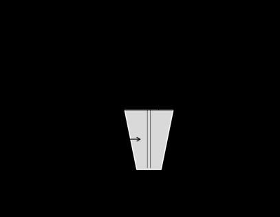
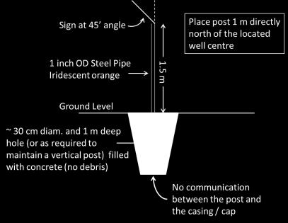
35 Post Requirements Page 33 of 37
36 6F Responsibility for Abandoned Wells Contents Objective Change of Ownership This section contains information on the impact of a change of operator for an abandoned well. Abandoned wells continue to be the responsibility of an identifiable operator. If the original operator transfers an abandoned well to a successor company, the successor assumes all responsibility for the control or further abandonment of the well and for the costs of doing that work. If a successor company transfers an abandoned well to a further successor company, the responsibility for the control or further abandonment of the well and for the costs of doing that work are also transferred. Reporting to the Regulator All changes in well operators must be reported to the Regulator within one month of the change. Page 34 of 37
37 7. APPLYING TO SUSPEND OR ABANDON A WELL Well Operation Application Requirements Suspending or abandoning a well is a well operation as defined in the OGDPR. Proposals for well operations must be approved by the Regulator before they can proceed. Application requirements depend on whether an Operations Authorization that includes suspension or abandonment within its scope is already in place for the well, as shown below. No Existing Operations Authorization Existing Operations Authorization Application Requirements Submission of Application for an Operations Authorization form and supporting documentation as required under OGOA and the OGDPR; and Submission of an Application to Alter the Condition of a Well form and supporting documentation as required under the OGDPR. Submission of an Application to Alter the Condition of a Well form and supporting documentation as required under the OGDPR. Application Forms Document Submission Guidelines Operations Authorization Process Application forms are available on the Regulator s website: Information on the number and type of copies required for an application can be found in the Document Submission Guidelines on the Regulator s website: OROGO reviews an application for an Operations Authorization by: Reviewing the application for completeness against the requirements of OGOA and the OGDPR; Ensuring an approved Benefits Plan is in place that covers the scope of the proposed activity; Assessing whether sufficient consultation has taken place with potential affected Aboriginal governments and organizations; Confirming that the proposed work or activity conforms with the appropriate Land Use Plan (where available); Undertaking a technical review of the application; Issuing Information Requests (if additional information is required to complete the review); Ensuring the Regulator s preliminary screening obligations under the Mackenzie Valley Resource Management Act are met; and Page 35 of 37
38 Assessing the proof of financial responsibility required. Altering the Condition of a Well Process Timeframes for Decision Definition OROGO reviews an application to Alter the Condition of a Well by: Reviewing the application for completeness against the requirements of the OGDPR; Undertaking a technical review of the application; and Issuing information Requests (if additional information is required to complete the review). OROGO s standards for processing applications are: For Operations Authorizations related to exploratory work, a maximum of 90 calendar days from receipt of a complete application, not including any additional time required to complete an environmental assessment or environmental impact assessment. For Well Approvals (including well suspensions and abandonments) under an existing Operations Authorization, a maximum of 30 calendar days from receipt of a complete application. A complete application contains all of the information required under OGOA and the OGDPR and requires confirmation of an approved benefits plan. Page 36 of 37
39 8. REGULATOR S SIGNATURE BLOCK These Suspension and Abandonment Guidelines and Interpretation Notes are issued under section 18 of the Oil and Gas Operations Act effective MONTH/DAY/YEAR. Louis Sebert Regulator Page 37 of 37
Reclassification and Recompletion
 Reclassification and Recompletion Guideline PNG024 September 2015 Revision 1.0 Governing Legislation: Act: The Oil and Gas Conservation Act Regulation: The Oil and Gas Conservation Regulations, 2012 Record
COGCC OPERATOR GUIDANCE MECHANICAL INTEGRITY TEST GUIDANCE: PRACTICES AND PROCEDURES
 COGCC OPERATOR GUIDANCE MECHANICAL INTEGRITY TEST GUIDANCE: PRACTICES AND PROCEDURES DOCUMENT CONTROL: Created Date: May 06, 2013 Last Updated Date: September 15, 2015 Last Updated By: Stuart Ellsworth
Disposal/Injection Well Pressure Test Report (H-5)
") RAILROAD COMMISSION OF TEXAS Disposal/Injection Well Pressure Test Report (H-5) Lauryn McFarland Engineering Technician Summary When Mechanical Integrity Test (MIT) is required How to file MIT How to perform
RAILROAD COMMISSION OF TEXAS Disposal/Injection Well Pressure Test Report (H-5) Lauryn McFarland Engineering Technician Summary When Mechanical Integrity Test (MIT) is required How to file MIT How to perform
the annulus between the second casing string and the surface casing [must be] open to the atmosphere in the manner described in subsection (2).
![the annulus between the second casing string and the surface casing [must be] open to the atmosphere in the manner described in subsection (2).](/thumbs/81/84166815.jpg "the annulus between the second casing string and the surface casing [must be] open to the atmosphere in the manner described in subsection (2).") Bulletin 2011-35 December 20, 2011 Surface Casing Vent Requirements for Wells This bulletin clarifies Section 6.100(4) of the Oil and Gas Conservation Regulations (OGCR) and provide additional surface
Bulletin 2011-35 December 20, 2011 Surface Casing Vent Requirements for Wells This bulletin clarifies Section 6.100(4) of the Oil and Gas Conservation Regulations (OGCR) and provide additional surface
Casing and Cementing Requirements
 Directive PNG005 May 2018 Revision 2.0 Governing Legislation: Act: The Oil and Gas Conservation Act Regulation: The Oil and Gas Conservation Regulations, 2012 Order: 148/18 Record of Change Revision Date
1 Introduction Purpose of the Directive AER Requirements What s New in This Edition Overview...
 Directive 020 Release date: March 15, 2016 Effective date: March 15, 2016 Replaces previous edition issued June 9, 2010 Well Abandonment The Alberta Energy Regulator has approved this directive on March
Abandonment Program for Paramount Fort Liard F 36
 Abandonment Program for Paramount Fort Liard F 36 Well Name: Paramount et al Liard F 36 Area: 60 0 10 N, 123 0 15 W Location: Latitude: 60 0 05 27 Longitude: 123 0 22 00 UWI: 300F366010123150 WID: 1841
Practice Exam IADC WellSharp Driller and Supervisor
 Workover & Completion Day 4 1. In a workover operation of a shut in well a Lubricator is being used together with a Wireline BOP / Wireline Valve. Which Barrier is classified as the Primary Barrier? A.
Texas Administrative Code
 TITLE 16 PART 1 CHAPTER 3 RULE 3.13 Texas Administrative Code ECONOMIC REGULATION RAILROAD COMMISSION OF TEXAS OIL AND GAS DIVISION Casing, Cementing, Drilling, Well Control, and Completion Requirements
EXAMINER S REPORT AND RECOMMENDATION STATEMENT OF THE CASE
 OIL AND GAS DO0KET NO. 01-0249550 THE APPLICATION OF REGENCY FS LP UNDER RULE 36 AND RULE 46 TO DISPOSE OF OIL AND WASTE CONTAINING HYDROGEN SULFIDE GAS INTO ITS TILDEN GPI WELL NO. 1, TILDEN, S. (WILCOX
1. UPDATE 12/12/2014: What wells are regulated under the MIA Program? Must they be drilled, stimulated, and completed? Must they be in production?
 PLEASE NOTE THAT ALL USES OF THE WORD OPERATOR IN THIS DOCUMENT REFER TO THE ACT 13 DEFINITION OF WELL OPERATOR AND THUS, REFERENCE THE PERMIT HOLDER (PERMITEE) FOR THE WELL. ANY ENFORCEMENT ACTIONS UNDER
Colorado Oil and Gas Conservation Commission
 Colorado Oil and Gas Conservation Commission http://cogcc.state.co.us/ FORM 5A Completed Interval Report INDUSTRY TRAINING Denver, Colorado November 27, 2012 Form 5A Completed Interval Report Introduction
Kerry A. Pollard Texstar Midstream Utility, LP Gallon E. Gray Phillip Zamzow EXAMINER S REPORT AND RECOMMENDATION STATEMENT OF THE CASE
 OIL AND GAS DOCKET NO. 01-0271975 THE APPLICATION OF TEXSTAR MIDSTREAM UTILITY, LP FOR AUTHORITY PURSUANT TO STATEWIDE RULES 9 AND 36 TO DISPOSE OF OIL AND GAS WASTE CONTAINING HYDROGEN SULFIDE INTO THE
Casing Design. Casing Design. By Dr. Khaled El-shreef
 Casing Design By Dr. Khaled El-shreef 1 Casing Design CONTENTS Function of Casing Casing Types & Tools Strength Properties Casing Specification Casing Design 2 1 RUNNING AND CEMENTING CASING Reasons for
Blowout during Workover Operation A case study Narration by: Tarsem Singh & Arvind Jain, OISD
 1. Introduction An incident of gas leakage from a well took place during workover operations. Subsequently, the gas caught fire on the fourth day in which twelve persons were injured. Two contract workers,
Mobeetie Resource Dev LLC EXAMINER S REPORT AND RECOMMENDATION STATEMENT OF THE CASE
 OIL AND GAS DOCKET NO. 10-0262937 THE APPLICATION OF MOBEETIE RESOURCE DEV LLC FOR A PERMIT TO DISPOSE OF FLUID CONTAINING HYDROGEN SULFIDE INTO A RESERVOIR NOT PRODUCTIVE OF OIL OR GAS, BUD HOGAN SWD
APPENDIX A1 - Drilling and completion work programme
 APPENDIX A1 - Drilling and completion work programme Information about the well and drilling To the extent possible, the international system of units (SI) should be adhered to, and the drilling programme
SECTION PRESSURE TESTING OF PIPING
 SECTION 15044 PRESSURE TESTING OF PIPING PART 1 - GENERAL 1.01 DESCRIPTION A. Scope of Work: This section specifies the leakage and pressure testing of piping. B. Testing Records: PART 2 - PRODUCTS 2.01
RULES OF THE OIL AND GAS PROGRAM DIVISION OF WATER RESOURCES CHAPTER DRILLING WELLS TABLE OF CONTENTS
 RULES OF THE OIL AND GAS PROGRAM DIVISION OF WATER RESOURCES CHAPTER 0400-52-06 DRILLING WELLS TABLE OF CONTENTS 0400-52-06-.01 Drilling Equipment 0400-52-06-.03 Casingheads 0400-52-06-.02 Blowout Prevention
Enbridge G & P (East Texas) LP EXAMINER S REPORT AND PROPOSAL FOR DECISION STATEMENT OF THE CASE
 LP EXAMINER S REPORT AND PROPOSAL FOR DECISION STATEMENT OF THE CASE") OIL AND GAS DOCKET NO. 05-0263914 THE APPLICATION OF ENBRIDGE G & P (EAST TEXAS) LP FOR AUTHORITY PURSUANT TO STATEWIDE RULES 9 AND 36 TO DISPOSE OF OIL AND GAS WASTE CONTAINING HYDROGEN SULFIDE INTO ITS
OIL AND GAS DOCKET NO. 05-0263914 THE APPLICATION OF ENBRIDGE G & P (EAST TEXAS) LP FOR AUTHORITY PURSUANT TO STATEWIDE RULES 9 AND 36 TO DISPOSE OF OIL AND GAS WASTE CONTAINING HYDROGEN SULFIDE INTO ITS
DEPARTMENT OF ENVIRONMENTAL PROTECTION Office of Oil and Gas Management
 DEPARTMENT OF ENVIRONMENTAL PROTECTION Office of Oil and Gas Management DOCUMENT NUMBER: 800-0810-003 TITLE: EFFECTIVE DATE: AUTHORITY: POLICY: PURPOSE: APPLICABILITY: DISCLAIMER: Guidelines for Development
OCEAN DRILLING PROGRAM
 BIH OCEAN DRILLING PROGRAM www.oceandrilling.org Scientifi c Application Packers A packer is an inflatable rubber element that inflates to seal the annular space between the drill string and the borehole
PENNSYLVANIA DEPARTMENT OF ENVIRONMENTAL PROTECTION
 Page 1 of 9 PENNSYLVANIA DEPARTMENT OF ENVIRONMENTAL PROTECTION COMPLIANCE DEMONSTRATION INSTRUCTIONS FOR THE CATEGORY NO. 38 AIR QUALITY PERMIT EXEMPTION CRITERIA The Category No. 38 exemption criteria
W I L D W E L L C O N T R O L PRESSURE BASICS AND CONCEPTS
 PRESSURE BASICS AND CONCEPTS Pressure Basics and Concepts Learning Objectives You will be familiarized with the following basic pressure concepts: Defining pressure Hydrostatic pressure Pressure gradient
Monte Besler Consultant FracN8R Consulting LLC UNITED STATES
 Monte Besler Consultant FracN8R Consulting LLC UNITED STATES Engineered Safety and Environmental Aspects of Well Construction and Fracturing Design Monte Besler FRACN8R Consulting, LLC Surface Considerations
Perforating Options Currently Available in Horizontal Shale Oil and Gas Wells. Kerry Daly, Global BD Manager- DST TCP
 MENAPS 2013 Perforating Options Currently Available in Horizontal Shale Oil and Gas Wells Kerry Daly, Global BD Manager- DST TCP MENAPS 13-17 WELL FLOW MANAGEMENT TM Scope/ Contents: MENAPS 13-17 Study
A PROACTIVE APPROACH TO ADDRESSING ANNULAR PRESSURE ISSUES AND STRAY GAS MIGRATION IN THE UNCONVENTIONAL SHALE PLAYS
 A PROACTIVE APPROACH TO ADDRESSING ANNULAR PRESSURE ISSUES AND STRAY GAS MIGRATION IN THE UNCONVENTIONAL SHALE PLAYS Authors: J. Daniel Arthur, P.E., SPEC, Tom Tomastik, Senior Geologist, Kris Anderson,
Oil, Gas and Salt Resources of Ontario
 Oil, Gas and Salt Resources of Ontario Provincial Operating Standards Version 2.0 Oil, Gas and Salt Resources of Ontario Provincial Operating Standards, Version 2.0 Version 2.0 of the Oil, Gas and Salt
Squeeze Cementing. Brett W. Williams Cementing Technical Advisor January 2016 Tulsa API Meeting
 Squeeze Cementing Brett W. Williams Cementing Technical Advisor January 2016 Tulsa API Meeting Definition Squeeze Cementing is the process of applying hydraulic pressure to force or squeeze a cement slurry
The Alberta Energy Regulator (AER) has approved this directive on January 31, Introduction Purpose of This Directive...
 has approved this directive on January 31, Introduction Purpose of This Directive...") Directive 008 Release date: January 31, 2018 Effective date: January 31, 2018 Replaces previous edition issued February 29, 2016 Surface Casing Depth Requirements The Alberta Energy Regulator (AER) has
Directive 008 Release date: January 31, 2018 Effective date: January 31, 2018 Replaces previous edition issued February 29, 2016 Surface Casing Depth Requirements The Alberta Energy Regulator (AER) has
Why Do Not Disturb Is a Safety Message for Well Integrity
 Why Do Not Disturb Is a Safety Message for Well Integrity Presented at the Practical Well Integrity Conference 9-10 December, 2014 in Houston By Ron Sweatman, Principal Advisor, Reservoir Development Services,
Is my well safe? Terje Løkke-Sørensen, CTO, add energy
 Is my well safe? Terje Løkke-Sørensen, CTO, add energy Introduction What is? a Safe Well?.. an Unsafe Well? A well with 2 well barriers both fully intact? A well with known issues risks can be managed?
OK.Company has 24 months from shut in to achieve suspension compliance. 29 Mar 2016
 The well suspension deadline date will be 12 months after the inactive status date. Contradicts Section 8 of Directive 13: Inactive wells must be suspended according to the requirements of this directive
Enbridge Pipelines (NE Texas) LP EXAMINER S REPORT AND RECOMMENDATION STATEMENT OF THE CASE
 LP EXAMINER S REPORT AND RECOMMENDATION STATEMENT OF THE CASE") OIL AND GAS DOCKET NO. 06-0262611 THE APPLICATION OF ENBRIDGE PIPELINES (NE TEXAS) LP FOR A PERMIT TO INJECT ACID GAS INTO ITS PITTSBURG GAS INJECTION LEASE WELL NO. 1 IN THE PROPOSED PITTSBURG (PALUXY
OIL AND GAS DOCKET NO. 06-0262611 THE APPLICATION OF ENBRIDGE PIPELINES (NE TEXAS) LP FOR A PERMIT TO INJECT ACID GAS INTO ITS PITTSBURG GAS INJECTION LEASE WELL NO. 1 IN THE PROPOSED PITTSBURG (PALUXY
SUPPLEMENT Well Control for Drilling Operations Workover & Completion for Drillers Core Curriculum and Related Learning Objectives
 SUPPLEMENT Well Control for Drilling Operations Workover & Completion for Drillers Core Curriculum and Related Learning Objectives Form WSP-02-DO-SU-WOC-D Revision 0 13 February 2015 DC 2015 COPYRGHT PROTECTED
Colorado Oil and Gas Conservation Commission (COGCC) Completed Interval Report, Form 5A Data Field Definitions
 Completed Interval Report, Form 5A Data Field Definitions") NOTE: Changes to the Form 5A, effective June 1, 2012, to accommodate the disclosure requirements are indicated by a preceding asterisk (*) and bold italics. All other fields are unchanged. FORM 5A HEADING
NOTE: Changes to the Form 5A, effective June 1, 2012, to accommodate the disclosure requirements are indicated by a preceding asterisk (*) and bold italics. All other fields are unchanged. FORM 5A HEADING
Development of a Subsurface Mudline Packer to Reduce Risk of Flow after Cementing and Sustained Casing Pressure, While Providing a Platform for P&A.
 Development of a Subsurface Mudline Packer to Reduce Risk of Flow after Cementing and Sustained Casing Pressure, While Providing a Platform for P&A. Sean Yakeley, Ed Wood and Yang Xu (Baker Hughes Inc)
SITE INSPECTION PROCEDURE FORM
 SITE INSPECTION PROCEDURE FORM The Oil and Gas Commission, as regulators of British Columbia s oil and gas industry focuses on effectively regulating and managing the Provinces oil and gas sector. The
Coal and Water Protection. PADEP: Well Plugging & Subsurface Activities Division Bureau of Oil and Gas Planning & Program Management
 Coal and Water Protection PADEP: Well Plugging & Subsurface Activities Division Bureau of Oil and Gas Planning & Program Management Review of Applicable Regulations & Laws Coal protective casing: A string
DB Bridge Plug. Features. Benefits. Applications
 DB Bridge Plug The WELLFIRST Premium Cast Iron Bridge Plug designed to run on electric line. Rated between 2000-10000-psi differential, and 300 F from above and below. Features Field Proven Design Constructed
W I L D W E L L C O N T R O L FLUIDS
 FLUIDS Fluids Learning Objectives You will learn about different fluids that can be used in well control. You will become familiar with the characteristics and limitations of fluids. You will learn general
Form 21 Mechanical Integrity Test
 Form 21 Mechanical Integrity Test Instructions for completing the Form 21, Mechanical Integrity Test for submission in eform. Required for eform submission Completed test form from field (please see Practices
Well Testing Plan. New York Marginal Well Study. Introduction. I. Tests to be Conducted. II. Testing Procedures
 Well Testing Plan New York Marginal Well Study Introduction The Independent Oil and Gas Association of New York, Inc. (IOGANY) has been awarded funding for a Marginal Well Testing Program from the New
OCTOBER 2017 ISSUE Page 1 of 7
 Field testing is performed on fully assembled pipelines for the purpose of determining pipeline acceptability. Following visual acceptance of joints and pipeline components, pressure pipelines in their
Contact Information. Progressive Optimization Service. We Provide: Street Bay #2. Grande Prairie, AB T8V - 4Z2
 Progressive Optimization Services (P.O.S.) is an Oil and Gas Optimization Service company based out of Grande Prairie, Alberta with offices in Edson, Alberta and Ft St John British Columbia our operations
Directive 059: Well Drilling and Completion Data Filing Requirements
 Directive 059 Directive 059: Well Drilling and Completion Data Filing Requirements December 19, 2012 Effective June 17, 2013, the Energy Resources Conservation Board (ERCB) has been succeeded by the Alberta
HYDROSTATIC LEAK TEST PROCEDURE
 This information is proprietary and shall not be disclosed outside your organization, nor shall it be duplicated, used or disclosed for purposes other than as permitted under the agreement with Kinetics
TECHNICAL DATA Q= C. Table 1 - Specifications
 September 25, 2013 Pressure Regulation 537a 1. Description The Model B-3 Pilot Operated Pressure Control Valve is a factory assembled unit. The unit consists of a Model J-2 Halar coated Flow Control Valve,
Advanced Applications of Wireline Cased-Hole Formation Testers. Adriaan Gisolf, Vladislav Achourov, Mario Ardila, Schlumberger
 Advanced Applications of Wireline Cased-Hole Formation Testers Adriaan Gisolf, Vladislav Achourov, Mario Ardila, Schlumberger Agenda Introduction to Cased Hole Formation tester Tool specifications Applications
Float Equipment TYPE 925/926
 Type 925 Float Collar Plunger Valve Float Equipment For less demanding well conditions, such as shallower depths or lower pressures, Top- Co offers economical float equipment certified to API RP 10F category
SUPPLEMENT Well Control for Drilling Operations Workover & Completion for Supervisors Core Curriculum and Related Learning Objectives
 SUPPLEMENT Well Control for Drilling Operations Workover & Completion for Supervisors Core Curriculum and Related Learning Objectives Form WSP-02-DO-SU-WOC-S Revision 0 13 February 2015 DC 2015 COPYRGHT
API Piping Plan 62: A Reliable Quench System
 MAY05PUMPS&SYSp24-33 4/19/05 4:04 PM Page 24 It s one of the few methods you have to control the environment outside a mechanical seal. By Keith Schindler, PE, Schindler Engineering, Inc., and Paul McMahan,
PROPOSED NEW SUB- CODE 1 RIG UP AND TEAR. Possibly Fits into Existing Code. 7/26/2018 Review PROPOSED NEW CODE EXISTING OPERATION
 NW NW 1 RIG UP AND TAR 1 no sub-code RIG UP AND TAR DOWN Start: Rig released from previous well, nd: Rig fully rigged up, acceptance tests successfully completed, and signed off. DOWN 1 1 Rig Under Tow
PETROLEUM: Well operations and well examination schemes
 H E A LT H & S A F E T Y AT WO R K HSWA AC T INTERPRETIVE GUIDELINES PETROLEUM: Well operations and well examination schemes These guidelines cover part 6 of the Health and Safety at Work (Petroleum Exploration
CLASS D - SENSITIVE LEAK TEST GAS AND BUBBLE METHOD. 1.1 To provide definitive requirements for PNEUMATIC pressure testing of piping systems.
 Page 1 of 7 CLASS D - SENSITIVE LEAK TEST GAS AND BUBBLE METHOD 1. SCOPE 1.1 To provide definitive requirements for PNEUMATIC pressure testing of piping systems. 1.2 The piping system as used herein is
Inflatable Packer Single & Double. Single & Double Packer Dimension. Wireline Packer. Water Testing Packer (WTP) Packer
 Packer") Inflatable Packer Single & Double Single & Double Packer Dimension Wireline Packer Water Testing Packer (WTP) Packer Packer Working Pressure & Depth Chart Packer Water Hand Pump Packer Air Driven Pump
Inflatable Packer Single & Double Single & Double Packer Dimension Wireline Packer Water Testing Packer (WTP) Packer Packer Working Pressure & Depth Chart Packer Water Hand Pump Packer Air Driven Pump
1 Scope... 2 Functions of cementing float equipment... 3 Definitions... 4 Calibration... 5 Test Categories... 6 General...
 American Petroleum Institute Contents Page 1 Scope... 2 Functions of cementing float equipment... 3 Definitions... 4 Calibration... 5 Test Categories... 6 General... 7 Apparatus and Materials... 8 High-temperature/high-pressure
Railroad Commission of Texas. Chairman Barry T. Smitherman Commissioner David Porter Commissioner Christi Craddick
 Railroad Commission of Texas Chairman Barry T. Smitherman Commissioner David Porter Commissioner Christi Craddick 1 RRC Regulations Primary directives: - Prevent Waste - Promote Conservation - Protect
HOT OILING OPERATIONS ALL HSE PRC 172. Approved By: Manager, HSE Performance Assurance. Table of Contents
 Owner: HSE Performance Assurance ALL HSE PRC 172 Approved By: Manager, HSE Performance Assurance Retention Code: CG01 CA Revised: March 2015 Review Frequency: Five years or less Table of Contents 1.0 Purpose...
ASSE International Product (Seal) Listing Program
 Listing Program") ASSE International Product (Seal) Listing Program ASSE 1070-2015 / ASME A112.1070-2015 / CSA B125.70-15 Performance Requirements for Water Temperature Limiting Devices Manufacturer: Contact Person: E-mail:
ASSE International Product (Seal) Listing Program ASSE 1070-2015 / ASME A112.1070-2015 / CSA B125.70-15 Performance Requirements for Water Temperature Limiting Devices Manufacturer: Contact Person: E-mail:
TECHNICAL DATA. the Viking Pilot Pressure Regulating Valve 1 Model A-1 Speed Control Assembly: OBSOLETE. the Viking Speed Control Assembly 1
 November 30, 1994 534 a 1. PRODUCT NAME VIKING 2" (50mm), 3" (75mm), 4" (100mm), 6" (150mm) 2. MANUFACTURER THE VIKING CORPORATION 210 N. Industrial Park Road Hastings, Michigan 49058 U.S.A. Telephone:
GEOTHERMAL WELL COMPLETION TESTS
 GEOTHERMAL WELL COMPLETION TESTS Hagen Hole Geothermal Consultants NZ Ltd., Birkenhead, Auckland, New Zealand. ABSTRACT This paper reviews the measurements that are typically made in a well immediately
New Hampshire Public Utilities Commission CFR 49 Part 192 Regulations. MINIMUM Pipeline Safety Regulations
 New Hampshire Public Utilities Commission CFR 49 Part 192 Regulations MINIMUM Pipeline Safety Regulations Application for Jurisdictional LPG Operators 1 Pipeline Safety Regulations 49 CFR Part 192 (NOTE:
Date of Issue: July 2016 Affected Publication: API Specification 16C, Choke and Kill Equipment, Second Edition, March 2015 ADDENDUM 1
 Date of Issue: July 2016 Affected Publication: API Specification 16C, Choke and Kill Equipment, Second Edition, March 2015 ADDENDUM 1 Page 16, Section 4.6, delete the entire section and renumber all subsequent
DEPARTMENT OF ENVIRONMENTAL PROTECTION Office of Oil and Gas Management
 DEPARTMENT OF ENVIRONMENTAL PROTECTION Office of Oil and Gas Management DOCUMENT NUMBER: 800-0810-003 TITLE: EFFECTIVE DATE: AUTHORITY: POLICY: PURPOSE: APPLICABILITY: DISCLAIMER: Guidelines for Development
INTERPRETATION NOTE ISSUED UNDER THE PETROLEUM DRILLING REGULATIONS (CNR 1150/96)
") BOP CLASSIFICATION SYSTEM FOR ONSHORE NEWFOUNDLAND AND LABRADOR INTERPRETATION NOTE ISSUED UNDER THE PETROLEUM DRILLING REGULATIONS (CNR 1150/96) PREPARED BY THE PETROLEUM RESOURCE DEVELOPMENT DIVISION
BOP CLASSIFICATION SYSTEM FOR ONSHORE NEWFOUNDLAND AND LABRADOR INTERPRETATION NOTE ISSUED UNDER THE PETROLEUM DRILLING REGULATIONS (CNR 1150/96) PREPARED BY THE PETROLEUM RESOURCE DEVELOPMENT DIVISION
FREQUENTLY ASKED QUESTIONS
 What are some applications in which you ve successfully used this product? New Completions - Stage by Stage Diversion Between Frac plugs for Intra-Stage Diversion Replace Frac Plugs with Perf PODs - Full
Talk 2 Tree & Wellhead Valve Testing Leak Rate Acceptance. Talk 3 DHSV Control Line hydrocarbon Ingress measurement & acceptability
 Talisman energy COIN Virtual Meeting # 17 26 th January 2011 Darren Bewick Graeme Douglas Martin Forbes David McGuckien Matt Morrison Martin Mosley Talisman Energy UK Ltd (TLMUK), Aberdeen 1 Presentations
How HSE regulates onshore oil and gas
 Health and Safety Executive How HSE regulates onshore oil and gas Paul Bradley (Operations Manager Wells and Mines) Craig Norman (Well Engineering and Operations Inspector) Health & Safety Executive Health
Inflatable Packers for Grouting 11/10/00
 Introduction Inflatable Packers for Grouting 11/10/00 Inflatable packers are frequently used for grout injection in geotechnical applications for structural reinforcement and/or water-proofing of foundations,
Deepwater Horizon Incident Internal Investigation
 Not all Information has been verified or corroborated. Subject to review based on additional information or analysis. Deepwater Horizon Incident Internal Investigation 1 Areas of Discussion Investigation
MIA Training Example (Catalano 2H)
") MIA Training Example (Catalano 2H) The Catalano 2H is a relatively new 4-string gas well drilled in an area where active underground coal mining is taking place. It is a cased-hole completion and the production
MIA Training Example (Catalano 2H) The Catalano 2H is a relatively new 4-string gas well drilled in an area where active underground coal mining is taking place. It is a cased-hole completion and the production
Piped Air SCBA Refilling System Standard
 WALT WHITE Fire Chief 5770 Freeport Blvd., Suite 200 Sacramento, CA 95822-3516 Ph: (916) 808-1300 Fax: (916) 808-1629 www.sacfire.org Piped Air SCBA Refilling System Standard SCOPE: This specification
OIL AND GAS DOCKET NO
 OIL AND GAS DOCKET NO. 09-0241077 THE APPLICATION OF GILBOW TANK TRUCK SERVICE, INC., TO DISPOSE OF OIL AND GAS WASTE BY INJECTION INTO A POROUS FORMATION NOT PRODUCTIVE OF OIL OR GAS, GILBOW WELL NO.
TAQA North Ltd. Well Blowout W4M June 8, 2009
 TAQA North Ltd. Well Blowout 10-10-28-29W4M June 8, 2009 ERCB Investigation Report January 11, 2010 Report prepared by Brian Temple (Incident Investigator), Rondine Cabot (Field Surveillance), Mark R.
IWCF Equipment Sample Questions (Combination of Surface and Subsea Stack)
") IWCF Equipment Sample Questions (Combination of Surface and Subsea Stack) 1. Given the volumes below, how much hydraulic fluid will be required to carry out the following operations (no safety margin)?
IWCF Equipment Sample Questions (Combination of Surface and Subsea Stack) 1. Given the volumes below, how much hydraulic fluid will be required to carry out the following operations (no safety margin)?
BIMBAR INFLATABLE PACKERS AND ACCESSORIES
 BIMBAR INFLATABLE PACKERS AND ACCESSORIES Geopro supplies a complete range of inflatable packers in nine different diameters from 28 up to 170mm. All our packers made of BIMBAR rubber technology are reinforced
DESIGN DATA OBSOLETE. C. Inspections - It is imperative that the system be inspected and tested on a regular basis. See Inspection
 February 9, 1998 Foam 201a 1. DESCRIPTION A Deluge Bladder Tank Foam/Water System is a standard deluge system capable of discharging a foam/water solution automatically through open sprinklers, spray nozzles,
Worked Questions and Answers
 Worked Questions and Answers A Learning Document for prospective Candidates For the Rotary Drilling Well Control Test Programme Copyright, IWCF June 2000 Revision No.1, November 2000 IWCF 2000 page 1 of
DESIGN DATA A WET PIPE BLADDER TANK FOAM/WATER SYSTEM WITH HYDRAULICALLY ACTUATED DELUGE CONCENTRATE CONTROL VALVE
 February 9, 1998 Foam 101a A BLADDER TANK WITH 1. DESCRIPTION A Wet Pipe Bladder Tank Foam/Water System is a standard wet pipe automatic sprinkler system capable of discharging a foam/water solution automatically
OREGON HEALTH. Systems Public Water Supply Systems Community Water Supply Systems Source Water Protection
 In the administration of ORS 537.505 to 537.795, the Director of the Water Resources Department has statutory authority under the provisions of ORS 537.780 "to prescribe and enforce general standards for
SPE Forum: Source Control for Wells in Shallow Water. Lars Herbst, Gulf of Mexico Regional Director
 SPE Forum: Source Control for Wells in Shallow Water Lars Herbst, Gulf of Mexico Regional Director Agenda Introduction and Background Historical Well Control Events Scope of Discussion Scenario Driven
NATURAL GAS MAINTENANCE. Part 192 Subpart "M"
 NATURAL GAS MAINTENANCE Part 192 Subpart "M" CONTACT INFORMATION Pamela West Pipeline Safety Specialist U.S. Department of Transportation PHMSA Inspector Training and Qualifications Main: (405) 686-2310
Leak testing of Valves. Standards for acceptable Rates of Valve Leakage
 Leak testing of Valves Standards for acceptable Rates of Valve Leakage American Petroleum Institute (API) The API standard 598: Valve Inspection and Testing, covers the testing and inspection requirements
Self-managing shallow geothermal well systems
 GUIDELINES PRACTICE GOOD Self-managing shallow geothermal well systems FOR PCBUs WITH GEOTHERMALLY HEATED POOLS OR PLANT March 2018 These guidelines are for PCBUs (including local authorities) who have
Engineered solutions for complex pressure situations
 SPECIAL SERVICES Engineered solutions for complex pressure situations Cudd Energy Services (CES) delivers custom engineered solutions to resolve complex pressure situations resulting from equipment failure
Geotech 1.66 Auto-Reclaimer Installation and Operation
 Geotech 1.66 Auto-Reclaimer Installation and Operation Rev 10/19/12 Part # 16600165 TABLE OF CONTENTS CHAPTER 1: SYSTEM DESCRIPTION... 3 FUNCTION AND THEORY... 3 SYSTEM COMPONENTS... 4 CHAPTER 2: SYSTEM
Geotech 1.66 Auto-Reclaimer
 Geotech 1.66 Auto-Reclaimer Installation and Operation Rev 9 8/31/06 Part # 16600165 TABLE OF CONTENTS CHAPTER 1: SYSTEM DESCRIPTION... 3 FUNCTION AND THEORY... 3 SYSTEM COMPONENTS... 4 CHAPTER 2: SYSTEM
On-Off Connector Skirt
 On-Off Connector Skirt Retrievable Packers & Accessories The On-Off Connector Skirt is compact, reliable, fully sealing, J-type tubing disconnect device that automatically engages and releases with a small
Appendix C Field Testing of Pipelines
 1 (Normative) C1 Scope Appendix C is based on some of the test methods in AS/NZS 2566.2, section 6, and associated appendices. This appendix specifies suggested methods of test and their application to
The key to connectivity
 The key to connectivity Kerry Daly, Global BD Manager, Tubing Conveyed Perforating (TCP) First published by Oilfield Technology, November 2015 Connecting oil or gas-bearing formations with the wellbore
Abstract Objective Scope of Study Introduction Procedures
 AADE-05-NTCE-71 A Practical Solution to Control Gas Migration Ned Shiflet, Forest Oil Corporation; Michael O. Dion, TAM International; and David P. Flores, TAM International This paper was prepared for
Petroleum Development
 Petroleum Development Original Idea... It has been said, "oil is first found in the minds of explorationists." Usually, this is the case. An explorationist, utilizing available data and information, will
MAINTENANCE AND SAFETY OF CNG REFUELLING STATIONS
 ISSN 1172-3416 NZ GCP 2 : 1993 NEW ZEALAND GAS CODE OF PRACTICE for MAINTENANCE AND SAFETY OF CNG REFUELLING STATIONS Issued by the Secretary of Commerce in accordance with the Gas Act 1992 THE GAS ACT
Hydro-Mech Bridge Plug
 Manual No: 0620000303 Revision: F Approved By: Quality Engineer Date: 2014-9-9 Hydro-Mech Bridge Plug DESCRIPTION: Map Hydro-Mech Bridge Plug is hydraulically actuated and mechanically set. Compact, with
WELL SCAVENGER. Versatile wellbore clean-up tool for the most demanding operations
 WELL SCAVENGER Versatile wellbore clean-up tool for the most demanding operations WELL SCAVENGER: A versatile wellbore cleanup tool for flowrestricted applications The inability to recover wellbore debris
Representing EXAMINERS REPORT AND PROPOSAL FOR DECISION STATEMENT OF THE CASE
 OIL AND GAS DOCKET NO. 03-0231502 THE APPLICATION OF JOHNSON SANFORD OPERATING COMPANY TO AMEND ITS PERMIT TO DISPOSE OF OIL AND GAS WASTE BY INJECTION INTO A POROUS FORMATION PRODUCTIVE OF OIL OR GAS,
Proposed Uniform Standards for Equipment Leaks
 12 th LDAR Symposium May 15-16, 2012 New Orleans, LA Proposed Uniform Standards for Equipment Leaks Standards Certification Education & Training Publishing Conferences & Exhibits 1 Proposed LDAR Uniform
Chapter 4 Key Findings. 4 Key Findings
 Chapter 4 Key Findings 211 4 Key Findings 212 Chapter 4 Key Findings This summarizes the key findings of the investigation team based on its extensive review of available information concerning the Macondo
PIP PNE00012 Piping Examination and Leak Test Guide
 October 2017 Piping PIP PNE00012 Piping Examination and Leak Test Guide PURPOSE AND USE OF PROCESS INDUSTRY PRACTICES In an effort to minimize the cost of process industry facilities, this Practice has