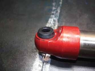
8. Carefully layout all the parts of the reservoir setup and clean any dirt, grime or dust from the parts. ( image 8 ) 8
|
|
|
- Eleanor Warner
- 5 years ago
- Views:
Transcription


 4 6.")
 5 7.")

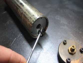
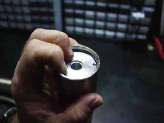
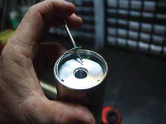
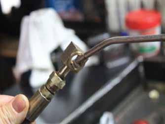
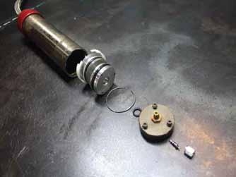
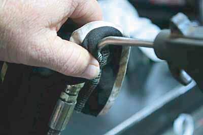
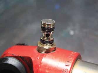
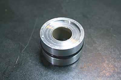
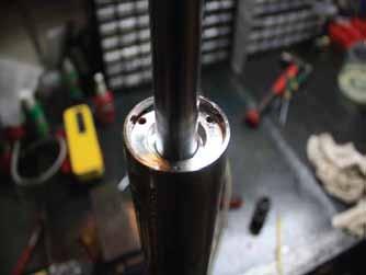
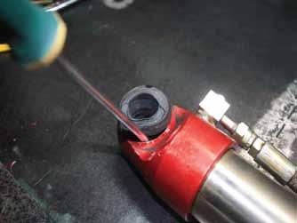
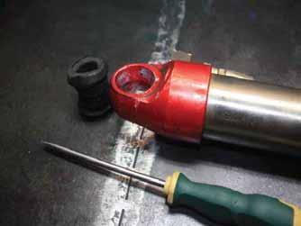
1 INSTRUCTIONS TO SERVICE AMADAXTREME SHOCKS 2.0 REMOTE RES AUSTRALIAN VERSION PART 1 - SERVICE THE RESERVOIR 1.Prior to cleaning the shock check for any leaks or signs of damage to the res, lines, bushes and main body, take note of any leaks or damage. Clean the shock down of any dirt, grease or grime; it is very important to use an extremely clean area to work on the shock. 2. If Nitrogen pressure is present in your reservoir just release the pressure, if there is no pressure completely remove the Schrader Valve as this is a indication you should replace the schrader valve as it may be leaking or damaged. ( image 1) 1 3. Use a 3mm Allen key to remove the end cap on the reservoir. ( image 2) 2 4. Using a seal pic carefully remove the seal behind the end cap, discard this seal. ( image 3 ) 4A - newer style res 4B - push the end cap in with your fingers to remove the circlip 4C - use a valve remover to gently pull out the end cap 3 4A 4B 4C 5. Using both hands depress the alloy retainer down enough to remove the circlip with a seal pic. ( image 4 ) 4 6. Remove the Circlip holding the high pressure line in place, use Circlip removers to perform this, be careful not to lose the Circlip. NOTE: there is 2 different style of fittings, a square block or a round fitting. ( image 5 ) 5 7. Using filtered clean / dry compressed air it is now necessary to blow out the floating piston from the reservoir, this is done by lining up an airline fitting with the inside hole of the high pressure line and covering the fitting with a rag tightly, depress the airline nozzle to POP out the piston, be careful as the piston will come out with a lot of force so do not have the reservoir facing any person. (Image 6 and 7 ) Carefully layout all the parts of the reservoir setup and clean any dirt, grime or dust from the parts. ( image 8 ) 8 9. Replace all 3 O-rings and the wear band with new parts supplied in the rebuild kit, do not put any of the parts together until later in the rebuild. ( image 9 ) 9 PAGE 1
 10 14.")


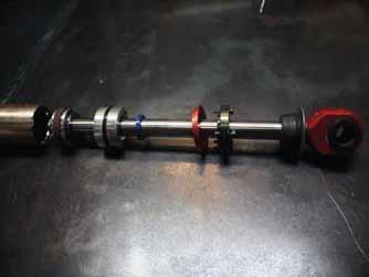
2 DISASSEMBLY OF THE MAIN SHOCK BODY 10. Check that there are no visibible oil leaks around the body and fittings. 11. Completely clean down the shock before proceeding. 12. Remove res if not done as described in the first section of these instructions. 13. Using a 3mm Allen key remove the 3 cap screws in the neck bush assembly ( image 10 ) Once you have removed the 3 cap screws lift up the top cap and push it to the top of the shock out of the way, also move the red seal retainer up out of the way. ( Image 11 ) You will now need to use both hands and using your fingers press down the seal housing just enough to expose the Circlip, if you cannot push this down with your fingers very carefully use a pin punch and a hammer but use extreme caution doing this as damage to the seal assembly may allow the seals to leak pressure. Remove the Cirlip Now that you have the circlip removed apply grease to the inside of the shock body where the circlip was. Use a seal pic and pick out the blue seal then have a friend give you assistance in this stage, with the shock body held in a vise by the lower fitting proceed to swiftly hit upwards on the shaft with both hands, this will allow the neck bush assembly and piston assembly to be removed, it is possible to pull the assembly out but usually this procedure works better. Your friend may need to assist in holding the bottom of the shaft or shock body as you try to hit it upwards. ( Image 13 ) These 2 images show the exact layout of the shaft, seals and piston. ( image 14 and 15) Carefully inspect the inside of the shock case and all the components of the shock assembly. All O-Rings and the wear band will be replaced but it is worth taking note of any damage to them for future problem solving if the same damage occurs at a later date. Remove both O-Rings on the high pressure line fitting; be extremely careful not to damage the new seals when fitting them on. ( image 16 ) The following steps are in regards to only servicing the shock, if you intend on re valving the shock you must read the re valve instructions. Check that the pin or eye fitting is properly tightened, if it appears to be loose it is recommended to apply locktite and properly tighten before proceeding further. Next remove the nut that holds the piston on the shaft, if you have a shaft that has been flared you must linish or grind the flared shaft flush to the nut before proceeding, DO NOT ATTEMPT TO UNDO THE NUT WITHOUT GRINDING THE FLARE. To undo the piston nut you must pull up the rubber bump and you will see where to put a thin spanner to hold the shock shaft, under no circumstances put the chrome shaft in the vise jaws. Assuming that your shaft has the flare and you have now ground it flush you can now remove the nut, before proceeding any further you must now clean any damaged threads, this is extremely important. If you did not have a flared shaft just proceed to remove the nut. Once the nut is removed and the thread is clean proceed to remove all the parts from the shaft and lay them out in order on a clean bench PAGE 2


 20 21 22 22.")


3 20. Carefully check the shock shaft for any damage, there must be no dints or scratches, if you have a dint in the shaft you can very carefully use a fine oilstone to smooth out the dint. If a dint has a raised edge it will cut the seal and make the shock leak straight away. Now that you have the piston off, all the parts can be removed off the shaft and you can proceed replace the seals in the correct order. Using a vise or similar object place the neck bush assembly on the Vise and carefully tap out the seal with a small pin punch, replace the seal with the new seal that is supplied, make sure you apply some shock oil to the Sealing areas. ( image 19 ) Using a pin punch hit out the rod guide and carefully tap in a new guide, be extremely careful not to scratch the new guide. A socket placed over the rod guide or a peice of tube can assist in pressing the guide back in place. Carefully replace the O-ring (Images 20 /21/ 22 ) Once you have done the rod guide push on the neck bush, blue seal, rod guide and the piston assembly in reverse of the way they come of the shaft. Apply Lock tight to the thread and tighten the nut to 30 NM for the 10mm nut or if your shock uses a 12mm nut tighten to 50 NM. With all the O-Rings and seals replaced with new items it is now time to replace the High Pressure line With the 2 x O-rings replaced on the fitting on the shock body, apply some oil to the o-rings and you can now very gently push the high pressure line back on to the shock body, be extremely Careful not to cut the O-ring while pushing the fitting together. ( Image 24 ) Have a friend assist you and hold the shock higher than the reservoir, fill the reservoir 5mm from the top with the recommended oil making sure not to create any more bubbles than possible, Pour the oil down the side of the reservoir body to stop bubbles forming. If you get bubbles let them dissipate before proceeding further. Lubricate the floating piston with oil and carefully push into the res with the dished out side facing the oil side. (Do not worry about the air beneath the piston yet) Be extremely careful not to damage the seal or the wear band. ( Image 25 and 26 ) Carefully put the shock body in a vise NOT ON THE CASE but on the eye or pin fitting and gently hang the res facing down below the shock body, doing this will now allow any air bubbles to rise up the shock case and escape. Use a handle of a hammer or any such item that will not damage the inside of the reservoir and push the piston up until you measure 170mm as pictured for remote res shocks, if you have coilovers the measurement will be 190 mm. ( Image 27 ) Now that the reservoir and high pressure line are free from air bubbles you can start to fill the shock with oil, slowly fill the shock to 50mm below the top of the shock. Wait for any bubbles to raise up before proceeding further. ( Image 28 ) Now that you have the oil in the shock to 40mm from the top you can carefully fit the shock shaft back into the case of the shock. Using your fingers compress the wear band in so it will easily fit into the case of the shock, now slowly push the shock shaft down into the body, If you do this too fast you will push the reservoir piston and you will have to do the process again, once the piston is beneath the oil you must start to rotate the shaft and slightly jiggle the shaft from side to side, this will expel any air bubbles below the shim pack, keep pushing the shaft down slowly until no more air bubbles are coming up. You want to try and have the oil level around 40mm from the top of the shock body to perform the next step, if the oil is lower than 40 mm keep slowly pushing the shaft in until the oil level comes up enough; if the oil level is too high (less than 40mm) pull the shaft out slowly until the level is close to 40mm. ( image 29 and 30 ) 30 PAGE 3


4 28. Make sure the Blue Seal is NOT located in the neck bush for this next step. Now that you have the oil close to 40mm from the top of the body you can apply some rubber grease to the O-ring of the neck bush assembly, gently push down and at the same time twist the neck bush so it pushes down past the Circlip groove, snap in the O-ring, don t push the neck bush any further than is needed. With the Circlip in place gently push down on the shaft of the shock to expel the remaining air bubbles, you will see the air bubbles rise pass the shaft and the neck bush, once all the bubbles have stopped proceed further. ( image 31,32, 33 ) Use your fingers to start pushing in the blue seal, after about half way you will need the assistance of your seal pick and carefully press in the seal, air and oil will be trapped under the seal so the very last part of the seal needs to have the seal pick gently pushed in between the side of the seal and the housing to release the last bit of excess oil and air. ( Image 34 ) Now that you have the seal in place use compress air and blow out the 3 holes in the neck bush assembly, apply a very small amount of lock tight to the 3 bolts and place the cap assembly back in position, evenly tighten the cap in place and firmly tighten the cap screws, (remember they are only tightening in alloy so don t over tighten) ( Image 35) Replace the reservoir alloy retainer back into the reservoir and snap in the Circlip, with the O-ring in place apply a small amount of grease around the seal. Using compress air blow out the 3 holes and apply a very small amount of lock tight onto the 3 cap screws. ( Image 36 ) Evenly tighten the end cap in place and refit the Schrader valve if it was previously removed. ( Image 37) If the bushes need replacing use a flat screw driver to remove the eye style bushes, silicon spray or soapy water can help push in the new bushes if they are tight, only use a very small amount of silicon spray or soapy water if needed, be very careful as the bush may pop out if you use you much. ( Images 38 / 39 / 40 ) Congratulations you have now just rebuilt your first Remote reservoir Shock. All that is needed now is to gas the shock with nitrogen gas. There is no right or wrong for gas pressures, you will find the higher the pressure the harder the ride may feel but you will have less shock fade on long hard drives, the lower the pressure is the softer the ride becomes, it is recommended to be around psi, most common pressure is around the 120psi when the shock leaves the factory. Please be aware that raising or lowering pressure to suit your ride is not the correct way to do it. There is no substitute for the correct valving and maintaining the gas pressures in a reasonable range. If you are using the shocks on a race truck I would recommend around the 200PSI and tourers and everyday 4wd s around 120 psi. Most Valving pressures are done are around 120 psi to get the shim packs correct,remember without the proper gas pressure check tool you will lose anywhere up to 20 psi just checking the shocks, so it will always pay to purchase the correct pressure testing tool before checking your shocks, These can be purchased through Superior Engineering as well as any nitrogen filling equipment. Thank you for purchasing Superior Engineering Products PAGE 4

5 PAGE 5


6 PAGE 6


7 PAGE 7


8 PAGE 8


9 PAGE 9
LIQUIP DRYBREAK COUPLER. API800 Series MAINTENANCE INSTRUCTIONS
 LIQUIP DRYBREAK COUPLER API800 Series MAINTENANCE INSTRUCTIONS API LOADING COUPLER TO API RP1004 June 2015 Issue: F M:\Product-Info\API8xx\6-Service-Maintenance\API800 MAINTENANCE INSTRUCTIONS 40183.doc
12S 1st Stage. -Maintenance Procedure-
 12S 1st Stage -Maintenance Procedure- 1 Warning! All maintenance and repair procedures MUST be performed by a Mares authorized Service Center and/or Distributor. Therefore, the information provided below
OPERATION MANUAL Please read this Operation Manual carefully before use, and file for future reference.
 English Lubrication Free Air Turbine Handpiece with Water Spray OPERATION MANUAL Please read this Operation Manual carefully before use, and file for future reference. OM-T0286E 001 Thank you for purchasing
Hydraulic Piston Accumulators
 Ride Control Engineering Services PWCE Extendavator Paul Wever Construction Equipment Co., Inc. P.O. Box 85 401 Martin Drive Goodfield, IL 61742-0085 Phone (309) 965-2005 Fax (309) 965-2905 1-800-990-PWCE
Reduce pressure zone device suitable for high and medium hazard rated applications Flanged end connections
 VALVCHEQ Backflow Preventers Reduce pressure zone device suitable for high and medium hazard rated applications Flanged end connections Features General application The RP03 provides protection from both
LIQUIP DRYBREAK COUPLER. LYNX Series MAINTENANCE INSTRUCTIONS
 LIQUIP DRYBREAK COUPLER LYNX Series MAINTENANCE INSTRUCTIONS API LOADING COUPLER TO API RP1004 February 2016 Issue: DRAFT A Issue: DRAFT - A 02/01/16 Page 1 CONTENTS LYNX Series Datasheet... 3 LYNX Series
APP pumps APP and APP Disassembling and assembling
 Service guide APP pumps APP 11-13 and APP 16-22 Disassembling and assembling hpp.danfoss.com Table of Contents Contents 1. Introduction... 2 2. Disassembling the pump... 3 3. Assembling the pump... 6 4.
Installation Procedure for your Disco Double Kit, by Airgun Lab, LLC.
 Disco Double Installation Instructions Copyright Airgun Lab LLC Rev D January 2016 page 1 of 6 Installation Procedure for your Disco Double Kit, by Airgun Lab, LLC. Step 1, gather tools. Tools required
VALVCHEQ BACKFLOW PREVENTERS FIGURE RP03
 Reduce pressure zone device suitable for high and medium hazard rated applications Flanged end connections FEATURES GENERAL APPLICATION The RP03 provides protection from both backsiphonage and backpressure
Regulators repair and maintenance. XS Compact 2nd stage. January 2014 Rev XSC /3 Ed. C /14 1
 XS Compact 2nd stage January 2014 Rev XSC /3 Ed. C /14 1 XS Compact 2nd stage WARNING! This manual is intended for use by expert technicians who have already received training in equipment repairs and
Disassembling and assembling APP and APP 16-22
 MAKING MODERN LIVING POSSIBLE Instruction Disassembling and assembling APP 11-13 and APP 16-22 ro-solutions.com Table of Contents 1. Disassembling...3 2. Disassembling the pump...3 3. Assembling the pump....7
MODEL 200 KNIFE GATE VALVES INSTALLATION & MAINTENANCE MANUAL
 MODEL 200 KNIFE GATE VALVES INSTALLATION & MAINTENANCE MANUAL Index 1. List of components / General arrangement 2. Description 3. Handling 4. Installation 5. Actuators / Operation 6. Maintenance a. Changing
Assembly Drawing: W-311B-A01, or as applicable Parts List: W-311B-A01-1, or as applicable Special Tools: , , &
 REDQ Regulators Model 411B Barstock Design Powreactor Dome Regulator OPERATION AND MAINTENANCE Contents Scope..............................1 Installation..........................1 General Description....................1
Instruction Manual. B&O WITH SLOPE BACK TENDER Live Steam
 Instruction Manual B&O 0-4-0 WITH SLOPE BACK TENDER Live Steam AML is proud to offer the famous B&O 0-4-0 of the Baltimore Waterfront. Four switchers were built in 1912 by Baldwin for the B&O. Initially
INSTRUCTION GUIDE S-WORKS ROAD CARBON CRANKSET (Carbon and Alloy OSBB cups)
") INSTRUCTION GUIDE S-WORKS ROAD CARBON CRANKSET (Carbon and Alloy OSBB cups) THIS BRIEF INSTRUCTION GUIDE CONTAINS IMPORTANT INFORMATION. PLEASE READ CAREFULLY AND STORE IN A SAFE PLACE. Congratulations!
INSTRUCTION GUIDE S-WORKS ROAD CARBON CRANKSET (Carbon and Alloy OSBB cups) THIS BRIEF INSTRUCTION GUIDE CONTAINS IMPORTANT INFORMATION. PLEASE READ CAREFULLY AND STORE IN A SAFE PLACE. Congratulations!
Hydraulic Punch Drivers
 SERVICE MANUAL 7804SB / 7806SB Quick Draw 7704SB / 7706SB Quick Draw Flex Quick Draw Hydraulic Punch Drivers Serial Codes AHJ and YZ Read and understand all of the instructions and safety information in
Freedom8 ShoeBox Compressor Manual
 Freedom8 ShoeBox Compressor Manual Warning!! This product is not a toy! Use or misuse can cause severe injury or death! Use only with adult supervision. This unit is only to be used with tanks, hoses and
Contents. Stainless Steel Side Block. 1.1 Separating the Side Block. Stainless Steel Side Block Reassembly of. Assembly from the Helmet Shell
 Separating the Side Block Assembly from the Helmet Shell Contents SSB-1 SSB-3 SSB-5 SSB-5 SSB-7 1.1 Separating the Side Block Assembly from the Helmet Shell 1.2 Side Block Assembly Replacement 1.3 Defogger
Detroit Speed, Inc. Rear Coilover Conversion Kit Camaro/Firebird P/N: &
 Detroit Speed, Inc. Rear Coilover Conversion Kit 1982-02 Camaro/Firebird P/N: 042440 & 042441 The Detroit Speed Inc., Rear Coilover Conversion Kit allows the latest in coilover spring/shock technology
OPERATING AND MAINTENANCE MANUAL
 CONTENTS PAGE INTRODUCTION 1 Installation Compatibility 1 Required Tools and Materials 1 Preparing Valve and Flanges 1 1.0 INSTALLATION 2 1.1 INSTALLATION OF ALL 2- TO 12-IN. SPAN-TYPE VALVES 2 1.2 INSTALLATION
Operation and Maintenance Instructions
 Hydratight Limited Bentley Road South Darlaston West Midlands WS10 8LQ United Kingdom Tel: +44 121 50 50 600 Fax: +44 121 50 50 800 E-mail: enquiry@hydratight.com Website: www.hydratight.com TOP COLLAR
STATIONARY TRUCK INTERNAL HALYARD V-CLEAT FLAGPOLES FOR QUICK AND PROFESSIONAL INSTALLATION READ ALL INSTRUCTIONS BEFORE PROCEEDING
 9390 South 300 West, Sandy, Utah 84070 801-562-0123 800-782-0500 ColonialFlag.com STATIONARY TRUCK INTERNAL HALYARD V-CLEAT FLAGPOLES FOR QUICK AND PROFESSIONAL INSTALLATION READ ALL INSTRUCTIONS BEFORE
SCUBAPRO. Balanced Power Inflator
 SCUBAPRO Balanced Power Inflator USE THIS GUIDE AS A REFERENCE WHEN SERVICING THE BALANCED POWER INFLATOR Important note: The following information is not designed to be a complete training guide for servicing
Instruction Manual - War Department Baldwin Live Steam Instruction Manual
 Instruction Manual - War Department Baldwin 4-6-0 Live Steam Instruction Manual ACCUCRAFT UK LTD PINEWOOD COTTAGE BROCKHURST CHURCH STRETTON SHROPSHIRE S6Y 6QY TEL/FAX: +44 (0) 1694 723799 www.accucraft.uk.com
Anderson Greenwood Series 93 Positive Pressure POSRV Installation and Maintenance Instructions
 Before installation these instructions must be fully read and understood Installation and maintenance instructions for Series 93 Positive Pressure Pilot Operated Safety Relief Valves (POSRV). The intent
Columbia Taping Tools. Hydra Reach Handle. Manual
 Columbia Taping Tools Hydra Reach Handle Manual Table of contents Warning 2 Introduction 3 Before you start, identify your handle 4 What is your problem? 5 Reservoir Upgrade 5 Setting up the loading system
MAINTENANCE PROCEDURE FOR X 650
 MAINTENANCE PROCEDURE FOR X 650 X 650 25. juli 2005-1/6 MAINTENANCE PROCEDURE FOR X 650 2 ND STAGE WARNING: This maintenance procedure is only for appointed Scubapro technicians that completed a course
Troyer s Gourd Rack 8 unit F R H O P
 B E A D I M-N L Vertical Parts F R H O P Horizontal Parts C G J Updated 11/16 Parts List A: Top of Pole B: Bottom of Pole C: 48 Ground Stake D: Top Perch rods 48 long E: Hub F: Rope Winder w/ attached
Santa Fe Cycles Assembly Guide Introduction
 Santa Fe Cycles Assembly Guide Introduction Congratulations on your purchase of your new Santa Fe bicycle. You have purchased a bicycle that has many features and qualities. Please take a few minutes and
35 TON HYDRAULIC PUNCH WARNING
 OPERATORS GUIDE REL-35T-PNC 35 TON HYDRAULIC PUNCH NOTICE Sizes, weights and tool specifications listed in this manual are subject to change without notice. Please consult factory for information and updates.
ACCUCRAFT UK LTD Unit 4, Long Meadow Industrial Estate, Pontrilas, Herefordshire. HR2 0UA Tel:
 1 ACCUCRAFT UK LTD Unit 4, Long Meadow Industrial Estate, Pontrilas, Herefordshire. HR2 0UA Tel: 01981 241380 www.accucraft.uk.com SAFETY FIRST OPERATING INSTRUCTIONS FLYING SCOTSMAN All our locomotives
INSTALLATION INSTRUCTIONS
 EDGEMERE CENTERSET LAVATORY FAUCET INSTALLATION INSTRUCTIONS 708.0 Thank you for selecting American Standard... the benchmark of fine quality for over 00 years. To ensure that your installation proceeds
PR4 Installation, Operation & Maintenance Instructions (DOT Certification Included)
") PR4 Installation, Operation & Maintenance Instructions (DOT Certification Included) March 2006 Form FVC 054 Rev. 6 KEEP THIS DOCUMENT WITH THE PRODUCT UNTIL IT REACHES THE END USER. The Passive - R4 device
PR4 Installation, Operation & Maintenance Instructions (DOT Certification Included) March 2006 Form FVC 054 Rev. 6 KEEP THIS DOCUMENT WITH THE PRODUCT UNTIL IT REACHES THE END USER. The Passive - R4 device
REV0709. Parts List. Hydraulic Cylinder Model MODEL C SINGLE-ACTING, SPRING RETURN HYDRAULIC CYLINDER. Max. Capacity: 55.2 Tons at 10,000 PSI
 REV0709 Parts List Hydraulic Cylinder Model 10312 MODEL C SINGLE-ACTING, SPRING RETURN HYDRAULIC CYLINDER Max. Capacity: 55.2 Tons at 10,000 PSI REV0709 Item No. Part No. No. Req d Description 1 10606
SPECIFICATIONS Type: Twin stack, single phase Tank: 4 gallon Air Output: PSI; PSI Max PSI: 125 PSI HP: 1.
 2 GALLON TWIN STACK AIR COMPRESSOR Model: 9526 DO NOT RETURN TO STORE. Please CALL 800-348-5004 for parts and service. CALIFORNIA PROPOSITION 65 WARNING: You can create dust when you cut, sand, drill or
JARVIS. Model CPE Hock and Neck Cutter EQUIPMENT... TABLE OF
 74 Hock and Neck Cutter EQUIPMENT SELECTION... Ordering No. TABLE OF CONTENTS... Page with Control Circuit. 4304003 only... 4304004 Balancer... 1350084 Control Circuit... 3350010 Air Hose (Yellow)... 3323003
RG1200 Service and Repair Manual
 Dive Rite RG 1200 Regulator Service and Repair Manual Page 1 Text and Photography by Pete Nawrocky Copyright ( ) 1999-2000, Lamartek, Inc., dba Dive Rite RG1200 Service and Repair Manual First Stage.........................................
Regulators repair and maintenance. 1st stage MC5. MC5 INT HZ MC5 DIN 300 bar HZ
 1st stage MC5 MC5 INT HZ 800098 MC5 DIN 300 bar HZ 800099 January 2008 Rev. MC5 / 1 Ed. A / 08 1 1st stage MC5 WARNING! This document is intended for experienced technical personnel who have already attended
Only. Gives You the TechLock. System Advantage ASSEMBLY, DISASSEMBLY AND TROUBLESHOOTING INSTRUCTIONS FOR 3000 SERIES FONTAINE
 April 00 Only Gives You the TechLock System Advantage ASSEMBLY, DISASSEMBLY AND TROUBLESHOOTING INSTRUCTIONS FOR 000 SERIES FONTAINE C o n n e c t y o u r b u s i n e s s w i t h F O N T A I N E April
Model year 2014 USER MANUAL
 Model year 2014 USER MANUAL WARRANTY Terms and conditions BOS MTB offers warranty on its products on the following terms : BOS MTB guarantees to the original purchaser that the BOS product for which they
Installation, Operation, and Maintenance Manual
 Installation, Operation, and Maintenance Manual Welker The information in this manual has been carefully checked for accuracy and is intended to be used as a guide for the installation, operation, and
STATIONARY TRUCK INTERNAL HALYARD CAM CLEAT FLAGPOLES FOR QUICK AND PROFESSIONAL COMMERCIAL INSTALLATION READ ALL INSTRUCTIONS BEFORE PROCEEDING
 9390 South 300 West, Sandy, Utah 84070 801-562-0123 800-782-0500 ColonialFlag.com STATIONARY TRUCK INTERNAL HALYARD CAM CLEAT FLAGPOLES FOR QUICK AND PROFESSIONAL COMMERCIAL INSTALLATION READ ALL INSTRUCTIONS
3/8" Dr. Air Butterfly Impact Wrench
 8192106 3/8" Dr. Air Butterfly Impact Wrench Owner s Manual Read and understand all instructions before use. Retain this manual for future reference. Specifications Construction: Polished aluminum and
Range Rover P38 EAS Air Suspension Valve Block O-rings and Diaphragm Seal Replacement Instructions Guide
 Range Rover P38 EAS Air Suspension Valve Block O-rings and Diaphragm Seal Replacement Instructions Guide by x8rltd on July 2, 2014 Intro: Range Rover P38 EAS Air Suspension Valve Block O-rings and Diaphragm
MUELLER GAS. No-Blo Operations Using D-5. Drilling Machine. Reliable Connections. General Information 2
 operating Instructions manual MUELLER GAS TAble of contents PAGE No-Blo Operations Using D-5 General Information 2 Installing No-Blo Service Tees, Service Stop Tees and Curb Stop Tees 3-8 Reconditioning
Repair instructions. Pivot bushing replacement. XL-AS10001RM-en-DE Rev B
 Repair instructions Pivot bushing replacement XL-AS10001RM-en-DE Rev B Table of contents Table of contents 1 General information... 3 1.1 Safety information...3 1.2 Legal information...4 1.3 Order and
Paddle Bar Replacement
 This procedure is to help facilitate the replacement of the 23 Paddle Bar Assembly on the ANKOM Dietary Fiber Analyzer. Note: The following items will be sent in a replacement package as part of the 23
Aluminum 13 cu tank Includes regulator Fill pressure: 3,000 psi (200 bar) Output: 1,100 psi +/- 10% (75bar)
 Output: 1,100 psi +/- 10% (75bar)") Aluminum 13 cu tank Includes regulator Patent numbers: 6,851,447 7,059,343 7,051,751 Fill pressure: 3,000 psi (200 bar) Output: 1,100 psi +/- 10% (75bar) Contents Safety system... 3 Fill your tank... 4
Aluminum 13 cu tank Includes regulator Patent numbers: 6,851,447 7,059,343 7,051,751 Fill pressure: 3,000 psi (200 bar) Output: 1,100 psi +/- 10% (75bar) Contents Safety system... 3 Fill your tank... 4
Service and Repair Operative Manual MC9 1 st STAGE. MC9 1 st Stage. 1 st STAGE MC9. Jannuary Rev. MC9 /B Ed. C/13
 MC9 1 st Stage 137 1 st STAGE MC9 Jannuary 2009 - Rev. MC9 /B Ed. C/13 138 WARNING! This manual is intended for use by expert technicians who should attend or have already received training in equipment
SERIES 2 RAMP OWNER S MANUAL TOOLS REQUIRED: BEFORE YOU BEGIN... Read and understand these instructions before beginning a ramp setup.
 SERIES 2 RAMP OWNER S MANUAL BEFORE YOU BEGIN... Read and understand these instructions before beginning a ramp setup. Use caution and care for your back when lifting, pushing, pulling, folding or unfolding
accidents which arise due to non-observance of these instructions and the safety information herein. SPECIFICATIONS
 18 GAUGE 1-1/4 INCH BRAD NAILER Model: 7611 CALIFORNIA PROPOSITION 65 WARNING: You can create dust when you cut, sand, drill or grind materials such as wood, paint, metal, concrete, cement, or other masonry.
PDY TON HYDRAULIC CRIMPING TOOL WARNING
 OPERATORS ORS GUIDE PDY-1220 12 TON HYDRAULIC CRIMPING TOOL All information found in this guide must be read and understood before use or testing of this tool. Failure to read and understand these warnings
INDOOR CYCLING BIKE SF-B1110 USER MANUAL
 INDOOR CYCLING BIKE SF-B1110 USER MANUAL IMPORTANT! Read all instructions carefully before using this product. Retain owner s manual for future reference. For customer service, please contact: support@sunnyhealthfitness.com
Installation Instructions
 Installation Instructions COLONY SOFT 7.0 Centerset Lavatory Faucet 7.0 with Speed Connect Drain Congratulations on purchasing your American Standard faucet with the Speed Connect drain, a features found
Bulletin /06/2012 Supersedes 10/23/00. Installation of John Crane Type 73 Inflatable Mechanical Seal. Page 01 of 10
 01 of 10 1. Carefully read all instructions and notes before installation. 2. Bench Pre-assembly: a. Insert the support ring (item #1) inside the inflatable boot (item #2) to form inflatable seal assembly
GAS STRUT SAFETY INFORMATION
 VERSION 4.0 - PAGE 1 CONTENTS 1. SAFETY REQUIREMENTS 2. INSTALLATION 3. DO S AND DON TS 4. PERIODIC INSPECTION 5. SERVICE LIFE 6. FUNCTIONAL SAFETY 7. DAMAGED GAS STRUTS VERSION 4.0 - PAGE 2 SAFETY REQUIREMENTS
A. TO PREPARE THE MACHINE FOR USE.
 INSTRUCTION MANUAL FOR THE ML120 STRINGING MACHINE. CONTENTS: A. TO PREPARE THE MACHINE FOR USE. 1. The assembly of frame with console and tooltray. 2. Fixing the lever of the tension unit. 3. Putting
Combination Breathing Apparatus
 and Combination Breathing Apparatus ULTRAVUE FACEPIECE TAL 502 (L) Rev. 0 MSA 2005 Prnt. Spec. 10000005389 (I) Mat. 10064385 Doc. 10064385 ULTRAVUE FACEPIECE COMPONENTS Item Part No. Description 800509
Spot Weld Drill Spot Weld Removal System Instruction Manual
 85-1001 Spot Weld Drill Spot Weld Removal System Instruction Manual Version 1.1 TABLE OF CONTENTS COMPONENT CHECKLIST 2 GENERAL SAFETY - READ BEFORE USING 3 INSTALL AND STORAGE MAINTENANCE INSTRUCTION
SECTION 2 RING MOUNT
 SECTION 2 RING MOUNT Rotax aircraft engines are manufactured and supported by Rotax GmbH of Austria. Read and understand the Rotax manuals completely before starting with the engine installation, as they
DBML-60/80 Squeeze Tool
 DBML-60/80 Squeeze Tool OPERATORS MANUAL Description The Mustang Model DBML-60/80 Hydraulic squeeze tool has been manufactured since 1995. A Mustang 3 3/4 bore doubleacting cylinder producing 41,000 lbs
BELT DRIVE INDOOR CYCLING BIKE SF-B1712 USER MANUAL
 BELT DRIVE INDOOR CYCLING BIKE SF-B1712 USER MANUAL IMPORTANT! Please retain owner s manual for maintenance and adjustment instructions. Your satisfaction is very important to us, PLEASE DO NOT RETURN
INSTALLATION & MAINTENANCE INSTRUCTION
 ARCHON Industries, Inc Liquid Level Gauges Models: BT-LLG ND-LLG INSTALLATION & MAINTENANCE INSTRUCTION Instruction No.: 1014.2 Revision Issued: 3/01/03 Approved: Engineering Manager Warning ONLY QUALIFIED
3M Liqui-Cel EXF-10x28 Series Membrane Contactor with ANSI or JIS Connections with Integrated End Caps
 Membrane Contactors 3M Liqui-Cel EXF-10x28 Series Membrane Contactor with ANSI or JIS Connections with Integrated End Caps Assembly and Disassembly Instructions 3M.com/Liqui-Cel TABLE OF CONTENTS I. Safety
Product Information News September 26, 2003
 Product Information News September 26, 2003 LEVER HEIGHT INSPECTION FOR FIREHAWK MMR MSA is announcing a revision to the instructions for the Firehawk MMR Second Stage Regulator as they relate to the air
!!!! SERVICE MANUAL PRESSURE POT 2 GALLON. Service Manual: LT Washington St 931 Progress Ave., #7
 EXEL North America, Inc. EXEL Industrial Canada, Inc. 1310 Washington St 931 Progress Ave., #7 West Chicago, IL 60185 Scarborough ONT, M1G 3V5 Ph : (800) 573 5554 Ph : (800) 450 0655 Fx : (800) 664 1511
310 SERIES TILT-TO-LOAD ROTATOR. The Specialist In Drum Handling Equipment
 OPERATOR S MANUAL FOR MORSE TILT-TO-LOAD DRUM ROTATOR SAFETY INFORMATION: While Morse Manufacturing Co. drum handling equipment is engineered for safety and efficiency, a high degree of responsibility
HYDRAULIC MOBILE LIFTING TABLE
 HYDRAULIC MOBILE LIFTING TABLE MODEL NO: HTL300 & HTL500 PART NO: 7610148 & 76210152 OPERATION & MAINTENANCE INSTRUCTIONS ORIGINAL INSTRUCTIONS GC1116 INTRODUCTION Thank you for purchasing this CLARKE
30T A/Manual Hydraulic Shop Press
 30T A/Manual Hydraulic Shop Press Operation Manual 1 1. Important Information 1.1 Safety Information 1.1.1 Hazard Symbols Used in the Manuals This manual includes the hazard symbols defined below when
MAGNETIC INDOOR CYCLING BIKE
 MAGNETIC INDOOR CYCLING BIKE SF-B1805 USER MANUAL IMPORTANT! Please retain owner s manual for maintenance and adjustment instructions. Your satisfaction is very important to us, PLEASE DO NOT RETURN UNTIL
Fit Testing. C50 APR New Equipment Training Module March 2010 Rev01
 Fit Testing Once all three steps are complete, the mask must be fit tested. This is done using the TSI Portacount Test System Before either of the tests begin, the mask must be set up properly. Fit and
OPERATION & MAINTENANCE INSTRUCTIONS
 1 /2 REVERSIBLE AIR DRILL MODEL NO: CAT123 PART NO: 3110879 OPERATION & MAINTENANCE INSTRUCTIONS GC1110 INTRODUCTION Thank you for purchasing this CLARKE product. Before attempting to use this product,
Instruction Manual Updated 7/26/2011 Ver. 2.2
 4-Unit Model MB HTHP Filter Press #171-50-4: 115-Volt #171-51-4: 230-Volt Instruction Manual Updated 7/26/2011 Ver. 2.2 OFI Testing Equipment, Inc. 11302 Steeplecrest Dr. Houston, Texas 77065 U.S.A. Tele:
L.Ph. Bolander & Sons 1355 Evans Ave. 800/
 L.Ph. Bolander & Sons 1355 Evans Ave. 800/434-5611 San Francisco, Ca. 94124 Fax 415/648-0402 GOUNDSET ALUMINUM FLAGPOLE INSTALLATION INSTRUCTIONS STEP 1: DIG THE HOLE TO THE DIMENSIONS LISTED BELOW STEP
4400 TwinHybrid Gas Seal
 4400 TwinHybrid Gas Seal EQUIPMENT PREPARATION MECHANICAL SEAL INSTALLATION INSTRUCTIONS 1 2 200.005" 0,13 mm 125 µ" 3,2 µm R a 3 4 32 µ" 0,8 µm R a 1000 ±.002" 0,05mm CAUTIONS These instructions are general
A-FRAME RESIN IN & OUT FLIP UP LADDER
 A-FRAME RESIN IN & OUT FLIP UP LADDER NE1222 NOTE FOR SAFETY PURPOSES ALL LADDERS SHOULD BE SECURED BY ATTACHING THEM TO THE TOP LEDGE OF THE POOL. (See step 13 for details) In order for the ladder to
Installation Instructions
 Installation Instructions COLONY SOFT 7.0 Single Control Lavatory Faucet with Speed Connect Drain Congratulations on purchasing your American Standard faucet with the Speed Connect drain, a feature found
CONSHELF XIV TECHNICAL MANUAL
 CONSHELF XIV TECHNICAL MANUAL Rev. 3/17 2 Conshelf XIV Technical Manual COPYRIGHT NOTICE This manual is copyrighted, all rights reserved. It may not, in whole or in part, be copied, photocopied, reproduced,
3M Liqui-Cel EXF-10x28 Series Membrane Contactor
 Membrane Contactors 3M Liqui-Cel EXF-10x28 Series Membrane Contactor Assembly and Disassembly Instructions 3M.com/Liqui-Cel TABLE OF CONTENTS I. Safety and Warning 3 II. Assembly Parts 4 III. Part Orientation
Technical Service Bulletin June 2015 TSB122.06
 Technical Service Bulletin June 2015 TSB122.06 Element Loading Guidelines This bulletin provides general information and guidelines for installing Hydranautics elements in order to provide optimally reliable
TECH SHEET ORANGE PIVOT TOOL INSTRUCTIONS
 page 1 ORANGE PIVOT TOOL INSTRUCTIONS This is a guide of how to change the pivot bearings on an Orange frame with a bore style pivot axle. 4 8 Bore Type Pivot Axle Horiz-Hold Type Pivot Axle Please read
Installation Troubleshooting Maintenance Instructions Installation / Start-up
 Model ZW207 Installation Troubleshooting Maintenance Instructions Installation / Start-up NOTE: Flushing of all pipe lines is to be performed to remove all debris prior to installing valve. 1. For making
600 / 600FC OWNER'S MANUAL
 PROGRESSION 600 / 600FC OWNER'S MANUAL Issue 2 / Version E - Dec. 10, 1997 Copyright 1997 GAMMA Sports - All Rights Reserved PROGRESSION 600 / 600FC OWNER'S MANUAL TABLE OF CONTENTS PAGE 1... WARRANTY
CHAPTER 5 REWIND STARTERS
 GENERAL INFORMATION CHAPTER 5 REWIND S Rewind starters used on vertical shaft Tecumseh engines are top mount horizontal pull style or side mount vertical pull style. Horizontal shaft engines use side mounted
SOTR Special Operations Tactical Respirator
 SOTR Special Operations Tactical Respirator OPERATOR S MANUAL FOR INDIVIDUAL RESPIRATORY PROTECTION OPS-CORE 2018 OMM G055-1000 REV. B INTRODUCTION ABOUT YOUR SOTR The Ops-Core Special Operations Tactical
Welker Sampler. Model GSS-1. Installation, Operation, and Maintenance Manual
 Installation, Operation, and Maintenance Manual Welker Sampler Model GSS-1 The information in this manual has been carefully checked for accuracy and is intended to be used as a guide to operations. Correct
Summary of Accumulators These operating instructions apply to the accumulators listed in the table shown below.
 Page 1 of 15 Summary of Accumulators These operating instructions apply to the accumulators listed in the table shown below. Model Number A25-XXXX-3.6K Series A40-XXXX-3K Series A40X-XXXX-3.6K Series A60-XXXX-3K
REL-510H WARNING NOTICE 12 TON SINGLE ACTING REMOTE HYDRAULIC CRIMPING HEAD
 OPERATORS ORS GUIDE REL-510H 12 TON SINGLE ACTING REMOTE HYDRAULIC CRIMPING HEAD Compatible with U style and RELIABLE R12 shell type 12 ton compression dies. RELIABLE EQUIPMENT & SERVICE CO., INC. 92 Steamwhistle
accidents which arise due to non-observance of these instructions and the safety information herein. SPECIFICATIONS
 18 GAUGE 2 INCH BRAD NAILER Model: 7555 CALIFORNIA PROPOSITION 65 WARNING: You can create dust when you cut, sand, drill or grind materials such as wood, paint, metal, concrete, cement, or other masonry.
DIRECT DRIVE DIXIE DOUBLE SEAMER Model 25D
 OPERATOR'S MANUAL DIRECT DRIVE DIXIE DOUBLE SEAMER Model 25D LUBRICATE DAILY: A. Gears inside gear housing at chuck shaft (1) Oil B. Seam rolls and cam rolls (4) - Oil C. Seam roll levers through gear
Operating Instructions
 Operating Instructions PRECISION AIR ENTRAINMENT METER Model: 34-3265 (CT-126A) TABLE OF CONTENTS I. GENERAL INFORMATION...1 II. RELATED USER DOCUMENTATION...2 FIGURE 1 -- AIR ENTRAINMENT METER...3 III.
AIR COMPRESSOR. Failure to follow all instructions as listed below may result in electrical shock, fire, and/or serious personal injury.
 2 GALLON AIR COMPRESSOR Model: 7517 DO NOT RETURN TO STORE. Please CALL 800-348-5004 for parts and service. CALIFORNIA PROPOSITION 65 WARNING: You can create dust when you cut, sand, drill or grind materials
TEM# Air Hammer Combo USER'S MANUAL
 Air Tools TEM# 40 Air Hammer Combo USER'S MANUAL Read carefully and understand RULES FOR SAFE OPERATION and instructions before operating. Failure to follow the safety rules and other basic safety precautions
15ME-014 INSTRUCTION MANUAL OF STERN TUBE SEALING TYPE EVK2RV. URL
 15ME-014 E INSTRUCTION MANUAL OF STERN TUBE SEALING TYPE EVK2RV URL http://www.kemel.com CONTENTS [A] Installation [B] Piping [C] Inspection [D] Handling [E] Parts replacement intervals [F] Handling check
SALCO PRODUCTS, INC. PRESSURE RELIEF VALVE STORAGE, INSTALLATION, OPERATING, MAINTENANCE/TESTING, AND INSPECTION INSTRUCTIONS
 STORAGE INSTRUCTIONS Until it is time to install a new or reconditioned valve on the car, the valve must be kept in its original packaging in order to protect it from dirt and damage. INSTALLATION INSTRUCTIONS
AR STYLE FIREARMS OWNER'S MANUAL: OPERATION, HANDLING, DISASSEMBLY / REASSEMBLY & SAFETY INSTRUCTIONS
 AR STYLE FIREARMS OWNER'S MANUAL: OPERATION, HANDLING, DISASSEMBLY / REASSEMBLY & SAFETY INSTRUCTIONS - DO NOT DISCARD THIS MANUAL - READ THIS MANUAL CAREFULLY, PAYING CLOSE ATTENTION TO THE INSTRUCTIONS
Auto-Rewind Hose Reels INSTRUCTION MANUAL FOR OXY-LPG MODEL
 Auto-Rewind Hose Reels INSTRUCTION MANUAL FOR OXY-LPG MODEL Introduction Thank you for purchasing a Retracta Auto Rewind Hose Reel. The Retracta range of hose reels are a breakthrough in industrial quality
Installation Instructions
 116-3027, 116-3017 X-Pando Adjustable Steel Protector Installation Instructions 1404 N. Marshall Ave. El Cajon CA. 92020 For technical support call us at (800) 368-3075 NB 6/28/10 607-0112 Step 1. Mounting
OPERATING INSTRUCTIONS. Parts List N. Note: Owner and operator MUST read and understand this operating instructions before use this lift table.
 OPERATING INSTRUCTIONS Parts List 770N te: Owner and operator MUST read and understand this operating instructions before use this lift table. Thank you for using this lift table. Your lift table is made
DelVal Flow Controls Private limited
 DelVal Flow Controls Private limited (A DIVISION OF DelTech CONTROLS LLC, USA) DelVal Series 50/5, 5A/5B Butterfly Valves INSTALLATION, OPERATION AND MAINTENANCE MANUAL ENGINEERING DATA SHEET E.D.S. NO