Portable Gas Monitor GX Operating Manual
|
|
|
- Allen Cain
- 5 years ago
- Views:
Transcription


1 PT-xxx Portable Gas Monitor GX-8000 Operating Manual Request for the Customers Read and understand this operating manual before using the gas monitor. Use the gas monitor in accordance with the operating manual. Regardless of warranty period, we shall not make any compensation for accidents and damage caused by using this product. Because this is a safety unit, daily maintenance, gas calibration for every six months, and regular maintenance must be performed. The sensors of the gas monitor, having its sensor life, must be replaced at regular intervals. If any abnormality was found in the gas monitor, notify them to Riken Keiki headquarters or authorized local representative immediately.
 in hazardous environments. The gas sample is sucked in by build-in micro pump. The battery can be selected either Li-ion battery or alkaline dry battery.")
2 Safety information The Portable Gas Monitor Model GX-8000 is a gas monitor designed to provide continuous exposure monitoring of combustible gas, oxygen (O2), toxic gas such as carbon monoxide (CO) and hydrogen sulfide (H2S) in hazardous environments. The gas sample is sucked in by build-in micro pump. The battery can be selected either Li-ion battery or alkaline dry battery. Li-ion battery unit is called BUL-8000 and alkaline dry battery unit is called BUD The battery unit can be changed even by the end users. Specification for safety Ga Ex ia IIC T4 II 1 G Ex ia IIC T4 Ambient temperature range for use -20 C to +50 C Ambient temperature range during battery charging 0 C to +40 C Electrical data Power supply of Li-ion battery unit : BUL-8000 Two parallel connected Li-ion cells used in battery pack BP-8000 are from type Maxell INR18650PB1. Um=250V. Power supply of alkaline battery unit : BUD-8000 Powered by three series AA size alkaline batteries, model LR6 by TOSHIBA. Backup battery type CR1220 manufactured by Maxell. Certificate numbers IECEx Certificate number IECEx KEM ATEX Certificate number KEMA 10ATEX 0085 List of standards IEC ed.4.0 IEC ed.5.0 IEC ed.2 EN :2006 EN :2007 EN :2007 WARNING Do not charge in hazardous location. Do not charge it expect by genuine charger. Do not replace battery unit in hazardous location. Do not replace dry batteries in hazardous location. Do not attempt to disassemble or alter the instrument. Use only battery unit type BUD-8000 with three series connected Alkaline AA batteries, type LR6 manufactured by Toshiba, or use chargeable battery unit type BUL INST. No A B C D E A: Manufacturing year (0-9) B: Manufacturing month (1-9,XYZ for Oct.-Dec.) C: Manufacturing lot D: Serial number E: Code of factory
3 Preface Thank you for choosing our portable gas monitor GX This gas monitor is a multi gas detector that enables simultaneous monitoring of combustible gases, oxygen, and toxic gases (hydrogen sulfide and carbon monoxide) in the air and high-concentration combustible gases in N2 and inert gases. Note that detection results are not intended to guarantee life or safety in any way. The gas monitor can measure two types of combustible gases, "general combustible gases (HC)" to be used in ordinary factories, oil tankers, etc. and "methane (CH4)" such as city gas and natural gas. The gas monitor comes in several types for different combinations of gases to be measured. Check the specifications of the gas monitor before use and conduct measurement properly in accordance with purposes. (See the list of gases to be measured at the end of this operating manual.) This manual explains how to use the gas monitor. Not only the first-time users but also the user who have already used a gas monitor must read and understand the operating manual before using this product. In addition to this operating manual, there are two other manuals available for the gas monitor: "Maintenance Manual" and "Data Logger Management Program Manual." Contact Riken Keiki if these manuals are needed. Throughout this manual, the following indications are used to ensure safe and effective work. DANGER WARNING CAUTION NOTE This message indicates that improper handling may cause serious damage on life, health or assets. This message indicates that improper handling may cause serious damage on health or assets. This message indicates that improper handling may cause minor damage on health or assets. This message indicates advice on handling GX-8000
4 <Contents> Preface Part Names Part names (Li-ion battery type) [Standard type] Part names (Dry battery type) [Option] LCD display How to Use Information for first-time users Preparation How to start and exit High-concentration combustible gas zero calibration (TYPE-A and TYPE-E models) FAIL display Measurement End of measurement Explanation of functions (1) Explanation of functions (2) DISPLAY switch Combustible gas range switching (TYPE-A and TYPE-E models) PEAK value display STEL value display TWA value display Alarm test (Full-scale/Alarm setpoint display) Pump OFF Station ID selection Manual memory storage and display Error (FAIL) display Dedicated battery unit Alarms Alarm types and patterns User actions for gas concentration alarms STEL alarm (short term exposure limit) TWA alarm (time-weighted average limit) Maintenance Daily maintenance Span adjustment Sensor replacement Filter replacement Li-ion battery unit or dry battery unit replacement [Option] Consumables Troubleshooting Specifications and Others GX-8000 specifications Combinations of detected gases by type GX-8000 accessories GX


5 1 Part Names 1-1. Part names (Li-ion battery type) [Standard type] 1 Part Names 1-1. Part names (Li-ion battery type) [Standard type] GX
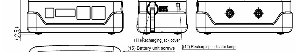
6 1 Part Names 1-1. Part names (Li-ion battery type) [Standard type] (1) LCD display: Displays gas concentrations, alarms, etc. (2) Buzzer sound opening: Emits a buzzer sound to indicate an alarm. (Do not block it.) (3) Alarm LED arrays: The lamp blinks in response to an alarm. (4) Infrared communication port: Used to carry out data communications with a PC in data logger mode. (5) /AIR switch: Keep this switch pressed to perform air calibration. See Page 16 for further details. (6) /RESET switch: When an alarm occurs, press this switch to reset the alarm. See Page 16 for further details. (7) DISPLAY switch: Press this switch to change between display modes. See Page 16 for further details. (8) POWER/ENTER switch: Turns on and off the power. See Page 16 for further details. (9) Gas inlet: Connect a sampling hose to this port. (10) Gas outlet: Exhausts the gas drawn into the gas monitor. (Do not block it.) (11) Recharging jack cover: Remove this cover to connect an AC powered charger and recharge the batteries. (12) Recharging indicator lamp: Lights up in red during recharging and goes off when recharging is completed. (13) Sensor cover: There are sensors inside. May be opened only when the sensor is to be replaced. (14) Activated carbon filter knob: Turn this knob to detach and replace the activated carbon filter. (15) Battery unit screws: Turn these screws to detach and replace the battery unit. GX
![1 Part Names 1-2. Part names (Dry battery type) [Option] 1-2. Part names (Dry battery type) [Option] (1) LCD display: Displays gas concentrations, alarms, etc.](/docs-images/84/89561466/images/7-1.jpg "(2) Buzzer sound opening: Emits a buzzer sound to indicate an alarm. (Do not block it.) (3) Alarm LED arrays: The lamp blinks in response to an alarm.")
7 1 Part Names 1-2. Part names (Dry battery type) [Option] 1-2. Part names (Dry battery type) [Option] (1) LCD display: Displays gas concentrations, alarms, etc. (2) Buzzer sound opening: Emits a buzzer sound to indicate an alarm. (Do not block it.) (3) Alarm LED arrays: The lamp blinks in response to an alarm. (4) Infrared communication port: Used to carry out data communications with a PC in data logger mode. (5) /AIR switch: Keep this switch pressed to perform air calibration. See Page 16 for further details. (6) /RESET switch: When an alarm occurs, press this switch to reset the alarm. See Page 16 for further details. (7) DISPLAY switch: Press this switch to change between display modes. See Page 16 for further details. (8) POWER/ENTER switch: Turns on and off the power. See Page 16 for further details. (9) Gas inlet: Connect a sampling hose to this port. (10) Gas outlet: Exhausts the gas drawn into the gas monitor. (Do not block it.) (11) Battery cover: Open and close this cover to replace the batteries. Must be closed while the gas monitor is in use. (12) Battery cover fixing screw: Fixes the battery cover. (13) Sensor cover: There are sensors inside. May be opened only when the sensor is to be replaced. (14) Activated carbon filter knob: Turn this knob to detach and replace the activated carbon filter. (15) Battery unit screws: Turn these screws to replace the dry battery pack GX-8000

8 1 Part Names 1-3. LCD display 1-3. LCD display GX
9 2 How to Use 2-1. Information for first-time users 2 How to Use 2-1. Information for first-time users The gas monitor is used to detect "oxygen-deficient air," "combustible gases," "hydrogen sulfide," and "carbon monoxide" that may be generated in a manhole, pit, underground premises, hold of a ship, etc. WARNING Do not disassemble the gas monitor or modify or change the circuit or structure, etc. Do not connect the sampling hose directly to a location with a pressure higher than the atmospheric pressure. The internal piping system may be damaged. Before use, check that there remains sufficient battery power. When the gas monitor is used for the first time or is not used for a long period, the batteries may be exhausted. Either fully recharge the batteries or replace them with new ones before use. (See Pages 22 and 23.) Perform gas calibration at fixed intervals. Pressing buttons unnecessarily may change the settings, preventing alarms from activating correctly. Operate the gas monitor using only the procedures described in this operating manual. Do not throw the gas monitor into fire. Do not use the gas monitor at higher temperatures, humidities, and pressures or at lower temperatures than the specified range. Normal displays and operations may be prevented. Do not store the gas monitor in a place exposed to direct sunlight or in a sun-heated car. Normal displays and operations may be prevented. Do not use the gas monitor near a device or equipment that emits strong electromagnetic waves. Do not drop or give shock to the gas monitor by, for example, relocating the gas monitor with a water trap, an optional accessory, attached. The gas inlet may be damaged GX-8000

 Li-ion batteries [Standard type] When the gas monitor is used for the first time, use the provided AC powered charger to")
![recharge the batteries. (See Page 22.) 2) Dry batteries type [Option] When dry batteries are used, put dry batteries in the battery pack. (Three AA alkaline batteries) (See Page 23.](/docs-images/84/89561466/images/10-2.jpg ") (3) Checking connection of the sampling hose Connect the sampling hose (spiral hose) securely to the gas inlet of the unit.")
, filter tube, etc.")
10 2 How to Use 2-2. Preparation 2-2. Preparation (1) Packing check After opening the package, check the gas monitor and accessories. If anything in the following list is not included, contact the dealer or Riken Keiki. Gas monitor GX-8000 and Li-ion battery pack AC powered charger (only for recharging type) Gas sampling probe Gas sampling hose Shoulder strap Operating manual Test certificate (2) Recharging Li-ion batteries or putting dry batteries 1) Li-ion batteries [Standard type] When the gas monitor is used for the first time, use the provided AC powered charger to recharge the batteries. (See Page 22.) 2) Dry batteries type [Option] When dry batteries are used, put dry batteries in the battery pack. (Three AA alkaline batteries) (See Page 23.) (3) Checking connection of the sampling hose Connect the sampling hose (spiral hose) securely to the gas inlet of the unit. Attach the gas sampling probe to the end of the sampling hose. Connect the sampling hose to GAS IN until it clicks into place. CAUTION Use only a sampling hose specified by Riken Keiki. Use the gas monitor with all of the gas sampling probe, gas sampling hose (with a float probe), filter tube, etc. connected so that no foreign matter is drawn into the sampling hose. Connect a gas sampling probe and a sampling hose by fastening them manually without using any tool. If they are fastened too tightly using a tool, the plastic part of the gas sampling probe may be broken. GX

11 2 How to Use 2-3. How to start and exit 2-3. How to start and exit Keep the POWER/ENTER switch pressed for three seconds or more to turn on the power. After conducting self diagnosis on power voltage, sensor connection, flow rate and other operations and functions, the gas monitor enters gas detection mode. Steps 1. Power-on Warm-up Gas concentration reading on the display screen 2. Measurement 3. Power-off GX-8000


12 2 How to Use 2-3. How to start and exit The operation after power-on is as follows: GX

13 2 How to Use 2-4. High-concentration combustible gas zero calibration (TYPE-A and TYPE-E models) WARNING Perform AIR calibration in fresh air. CAUTION In a location with sudden temperature changes over 15 degrees centigrade, let the gas monitor stand for about 10 minutes before performing AIR calibration High-concentration combustible gas zero calibration (TYPE-A and TYPE-E models) The models that can display combustible gas levels in two ways, "%LEL range" and "vol% range," need zero calibration using a base gas in order to measure the "vol% range" concentration correctly. (1) Fill a sampling bag with a base gas (such as N2 and an inert gas). (2) In a measurement screen, keep the /RESET switch pressed and press the DISPLAY switch. Press either the /AIR or /RESET switch and select VOL Z.CAL. Zero Point Calibration Screen (3) Press the POWER/ENTER switch once. The screen is changed to O2 and vol% display and VOL Z.CAL blinks in the lower row. Connect the sampling bag containing a base gas to the gas inlet (GAS IN). When the reading is stabilized, press the POWER/ENTER switch. Introduction of the base gas Blinking Blinking (4) When END is displayed, the calibration has been successfully completed. Remove the sampling bag from the gas inlet. (5) When FAIL is displayed, the calibration means to be failed. [If calibration failed at an oxygen concentration of 8% or higher] Press the /RESET switch to reset the error GX-8000
14 2 How to Use 2-5. FAIL display (6) After successful completion of calibration, press the /AIR or /RESET switch. When ESCAPE is displayed, press the POWER/ENTER switch. Zero Point Calibration Screen /AIR or /RESET switch Press the POWER/ENTER switch. (7) The measurement screen is displayed again FAIL display In normal operation, the screen display changes as shown in the previous section until the gas monitor is ready for measurement. However, the LCD display screen shows "FAIL" as shown in the following figure if the self diagnostic function detects an error in the gas monitor before or during measurement. See Page 22 for other FAIL displays and explanation of them. FAIL display examples AIR calibration failed AIR calibration failed. Press the RESET switch. If AIR calibration fails again, contact the dealer or Riken Keiki headquarters or authorized local representative. Battery voltage low The battery voltage is insufficient. Either recharge or replace the batteries. Sensor abnormality Detection is not possible due to a sensor abnormality. The failed sensor name is displayed together with FAIL SENSOR. [The display example shows "CO."] If this display is shown, request the dealer or Riken Keiki headquarters or authorized local representative to perform a maintenance on the gas monitor. VOL% zero calibration failed (only TYPE-A and TYPE-E models) Displayed to indicate a failure in zero point calibration for high-concentration combustible gas measurement. Press the RESET switch to reset the error. Calibration will be successful when the oxygen is less than 8%. GX
15 2 How to Use 2-6. Measurement 2-6. Measurement (1) Measurement method Bring the gas sampling probe or float probe to the measurement location and read the LCD measurement display when it stabilizes. Display example Display example CH 4 concentration: 0%LEL O 2 concentration: 20.9% CO concentration: 0 ppm H 2 S concentration: 0 ppm Time: 9:30 Battery level: Full DANGER While conducting measurement in a manhole or confined space, do not lean over or look into the manhole or closed space. It may lead to dangers because oxygen-deficient air or other gases may blow out. WARNING Do not block the buzzer sound hole. No alarm sound can be heard. If an oxygen deficiency or toxic gas (CO or H 2 S) alarm occurs, evacuate the area. After taking safety precautions, take appropriate actions such as introducing fresh air and sealing the generation source. Do not connect the sampling tube directly to a location with a pressure higher than the atmospheric pressure. The internal piping system may be damaged. If a low battery alarm occurs, gas detection cannot be conducted. If the alarm occurs during use, turn off the power and promptly recharge the batteries in a non-hazardous area. CAUTION Do not measure anything but air, combustible gases, or a mixture of vapors and toxic gases. Do not place the gas monitor where water or dirt gets accumulated. The gas monitor placed at such a location may malfunction due to water or dirt that gets into the buzzer opening, gas inlet, etc. The gas inlet and outlet of the gas monitor are not water-proof. Be careful not to let water get into these parts. Do not draw in rainwater or other water. Because this may cause trouble and gas cannot be detected. Do not drop or give shock to the gas monitor. The water-proof and explosion-proof properties and accuracy may be deteriorated. In a low-temperature environment, the operating time is shortened due to the battery performance property. When using this gas monitor in a hazardous area, take the following countermeasures for preventing dangers resulting from electrostatic charges. (1) Wear anti-static clothes and conductive shoes (anti-static work shoes). (2) For indoor use, use the gas monitor while standing on a conductive work floor (with a leakage resistance of 10 MΩ or less). Do not use the gas monitor while recharging it. If the combustible gas reading exceeds 100% LEL, the CO reading rises temporarily but this is not an abnormality GX-8000
16 2 How to Use 2-7. End of measurement NOTE The gas monitor, being compliant to IP67, is not water-pressure-resistant. Do not use the gas monitor where a high water pressure is applied to it (under a faucet, shower, etc.) or submerge it under water for a long time. Do not wash the gas monitor in a washing machine or ultrasonic cleaner. At a low temperature, the response of the LCD display may get slow down. (2) Precautions on operating environment Whereas the gas monitor can detect oxygen, combustible gases, hydrogen sulfide, and carbon monoxide, the measurement environment may include gases that have harmful effects on the sensors of this unit. The gas monitor cannot be used in the presence of the following gases: 1) Sulfides (such as H 2 S and SO 2 ) continuously existing in high concentrations 2) Halogen gases (such as chloride compounds and chlorofluorocarbons) 3) Silicone (Si compounds) Note that drawing in dirty water, dust, metallic powder, etc. will significantly deteriorate the sensor sensitivities. Be careful when the gas monitor is used in an environment where these elements exist. WARNING Do not use the gas monitor in the presence of the above gases (such as sulfides, halogen gases, and silicone), which may shorten the sensor life significantly or cause malfunctions such as inaccurate readings. In case the gas monitor is used for detection in the presence of silicone, etc., be sure to check the gas sensitivities before using it again. Do not submerge the gas monitor in a liquid other than water. The gas monitor is water-proof only in fresh water and running water, and not in hot water, salt water, detergent, chemicals, human sweat, etc. Do not jab the buzzer opening with a sharp-pointed item. The unit may malfunction or get damaged, allowing water or foreign matter, etc. to get inside. Do not affix a label on the infrared port. Infrared communications can no longer be conducted End of measurement Make the gas monitor draw in fresh air. After the display resets to zero (or 20.9% for oxygen), keep the POWER/ENTER switch pressed until the power is turned off. If the power is turned off before the display resets to zero (or 20.9% for oxygen), only the pump may operate (for 30 seconds at the longest). Count-down GX
17 2 How to Use 2-7. End of measurement CAUTION When the gas monitor is contaminated, clean it with a dustcloth, etc. after wetting it in water and wringing it out well. When cleaning the gas monitor, do not splash water over it or use organic solvents such as alcohol and benzene on it. The surface of the gas monitor may be discolored or damaged. When the gas monitor gets wet, water may remain in the buzzer sound opening or clearances. Drain water as follows: 1. Wipe away moisture on the gas monitor thoroughly using a dry towel, cloth, etc. 2. While holding the gas monitor firmly, shake it about ten times with the buzzer sound opening facing downward. 3. Wipe away moisture coming out from the inside thoroughly using a towel, cloth, etc. 4. Place the gas monitor on a dry towel, cloth, etc. and let it stand at normal temperatures. When stored or not in use for a long time, the gas monitor shall be kept under the following environmental conditions: (1) In a dark place under the normal temperature and humidity away from direct sunlight (2) In a place where gases, solvents or vapors are not present Store the gas monitor in a shipping carton, if any, in which the product was delivered. Store the gas monitor in a plastic bag if the shipping carton is not available. Store the gas monitor away from dust, etc. if the shipping carton is not available. CAUTION If the gas monitor is not used for a long time, turn on the power at least once every six months and check that the pump draws in air. The gas monitor, when not activated for a long time, may cease to work because of hardening of the grease in the pump motor GX-8000
 /AIR switch Press the /AIR switch to reset the readings to zero if incorrect readings are displayed at power-on or during measurement when there is no gas in the surroundings.")
 Combustible gas range setting, (2) PEAK value display, (3) STEL value display, (4) TWA value display, and (5) Full-scale/Alarm setpoint display The gas monitor, if not operated for 20 seconds in")
18 2 How to Use 2-8. Explanation of functions (1) 2-8. Explanation of functions (1) The gas monitor offers various functions. The functions can be called up using the switches. (1) /AIR switch Press the /AIR switch to reset the readings to zero if incorrect readings are displayed at power-on or during measurement when there is no gas in the surroundings. (The oxygen level is reset to 20.9%.) (2) DISPLAY switch Press the DISPLAY switch to change the display screen, check data, and change settings. (1) Combustible gas range setting, (2) PEAK value display, (3) STEL value display, (4) TWA value display, and (5) Full-scale/Alarm setpoint display The gas monitor, if not operated for 20 seconds in any of these modes, automatically reverts to the measurement mode. (3) /RESET switch Press the /RESET switch to reset a gas concentration alarm or other alarm that has occurred after checking it. (4) POWER/ENTER switch Press the POWER/ENTER switch to turn on or off the power, change the settings, etc. WARNING Pressing buttons unnecessarily may change the settings, preventing alarms from activating correctly. Operate the gas monitor using only the procedures described in this operating manual. CAUTION Press the /AIR switch after checking that a fresh air is present in the surroundings. If AIR calibration fails due to a sensor abnormality, a message appears, indicating which sensor failed. Do not remove the panel sheet on the LCD display and operation panel. The water-proof and dust-proof performances will be deteriorated. GX
19 2 How to Use 2-9. Explanation of functions (2) DISPLAY switch 2-9. Explanation of functions (2) DISPLAY switch Press the DISPLAY switch to display various screens. (Figures in the following displays are examples) 1. Combustible gas range setting 2. PEAK value display 3. STEL value display 4. TWA value display 5. Full-scale/Alarm setpoint display 6. Pump OFF 7. Station ID selection 8. Manual memory display Combustible gas range switching (TYPE-A and TYPE-E models) The models that can display combustible gas levels in two ways, "%LEL range" and "vol% range," automatically switch between these two displays according to the gas concentration, from "%LEL range" to "vol% range" and vice versa. (1) During vol% range measurement, "vol%" and "No ALARM" displays blink. (2) If the reading is 3 vol% or less and the oxygen concentration is 19.5% or more during vol% range measurement, keep the RESET switch pressed to forcibly change the display to the %LEL range. VOL% range measurement %LEL range measurement GX-8000
20 2 How to Use Combustible gas range switching (TYPE-A and TYPE-E models) (3) Measurement fixed to the vol% or %LEL range 1) Press the DISPLAY switch once. 2) Press the POWER/ENTER switch to change the setting. Press the DISPLAY switch if you choose not to change the setting. 3) Press the /AIR or /RESET switch. When ONLY VOL or ONLY LEL is displayed, press the POWER/ENTER switch. 4) When END is displayed, the change is completed. 5) Press the DISPLAY switch seven times to return to the measurement screen. (4) Switching the vol% or %LEL range back to the automatic range 1) Press the DISPLAY switch once. 2) Press the POWER/ENTER switch to change the setting. Press the DISPLAY switch if you choose not to change the setting. 3) Press the /AIR or /RESET switch. When AUTORANG is displayed, press the POWER/ENTER switch. GX

21 2 How to Use PEAK value display 4) When END is displayed, the change is completed. 5) Press the DISPLAY switch seven times to return to the measurement screen. WARNING No gas alarm is triggered in the combustible gas vol% range. The screen displays No ALARM while no alarm is triggered. No ALARM display CAUTION An oxygen concentration of 10% or more is required for the combustible gas %LEL sensor of the gas monitor to correctly detect gases and display concentrations. In an atmosphere with an oxygen concentration less than 10%, the combustible gas vol% sensor may conduct the detection PEAK value display Press the DISPLAY switch twice during measurement to display the maximum concentration (or minimum concentration for oxygen) detected during measurement from power-on to the present. Display example Combustible (methane): 10%LEL Oxygen: 20.8% Carbon monoxide: 80 ppm Hydrogen sulfide: 0 ppm The PEAK value display automatically reverts to the measurement screen in 20 seconds GX-8000
22 2 How to Use STEL value display STEL value display Press the DISPLAY switch three times during measurement to display the STEL value detected after power-on. (Only carbon monoxide and hydrogen sulfide) Display example Carbon monoxide: 80 ppm Hydrogen sulfide: 0 ppm The STEL value display automatically reverts to the measurement screen in 20 seconds TWA value display Press the DISPLAY switch four times during measurement to display the TWA value detected after power-on. (Only carbon monoxide and hydrogen sulfide) Display example Carbon monoxide: 20 ppm Hydrogen sulfide: 0 ppm The TWA value display automatically reverts to the measurement screen in 20 seconds. GX
 (1) Press the DISPLAY switch five times to enter the DISPLAY screen.")
 Press the /AIR or /RESET switch to select one of the following screens: Full scale First alarm (WARNING) Second alarm (ALARM)")
 After alarm test, press the DISPLAY switch five times to return to the measurement screen. 2-15.")

23 2 How to Use Alarm test (Full-scale/Alarm setpoint display) Alarm test (Full-scale/Alarm setpoint display) (1) Press the DISPLAY switch five times to enter the DISPLAY screen. Press the POWER/ENTER switch to enter the alarm setpoint display. To cancel, press the DISPLAY switch. (2) Press the /AIR or /RESET switch to select one of the following screens: Full scale First alarm (WARNING) Second alarm (ALARM) STEL alarm TWA alarm In either of the screens, press the POWER/ENTER switch to conduct alarm test. (3) After alarm test, press the DISPLAY switch five times to return to the measurement screen Pump OFF Battery consumption can be reduced by about 40% if the pump is turned OFF while going to a measurement location or having a break in measurement. It is recommended to turn off the power if no measurement is performed at least for 10 minutes. (1) Press the DISPLAY switch six times to enter the PUMP OFF screen. Press the POWER/ENTER switch to turn the pump OFF. Press the DISPLAY switch if you choose to cancel the operation GX-8000
24 2 How to Use Station ID selection (2) Press the POWER/ENTER switch to activate the pump and return to pump OFF input standby. Pump stopped POWER ENTER Pump OFF input standby (3) During pump OFF input standby, press the DISPLAY switch three times to return to the measurement screen Station ID selection Station IDs can be used to add preregistered location information to a data logger. See another manual entitled "Data Logger Management Program Manual" for detailed usage of a data logger. Note that selection of a station ID has no influence on concentration results of gas measurement. (1) Press the DISPLAY switch seven times to enter the station ID selection screen. Factory-set to numbers 000 to 255 Press the POWER/ENTER switch to change the station ID. Press the DISPLAY switch if you choose to cancel the operation. (2) Press the /AIR or /RESET switch to select a station ID. After selecting a station ID, press the POWER/ENTER switch. Press the DISPLAY switch if you choose to cancel the operation. (3) When END is displayed, the change is completed. GX
.")
 During measurement, keep the /RESET switch pressed and press the /AIR switch for one second or more.")
25 2 How to Use Manual memory storage and display Manual memory storage and display The data logger automatically stores the gas measurement results at regular time intervals (factory set to every five minutes). The function to store instantaneous values is called the "manual memory function." The values stored to the manual memory can be displayed. [Manual memory storage procedure] (1) During measurement, keep the /RESET switch pressed and press the /AIR switch for one second or more. (2) The memory number, storage date, and instantaneous value to be stored are displayed in turn. Memory number display Storage date display Display of an instantaneous value to be stored Press the POWER/ENTER switch to execute storage. (An instantaneous value at the point of time for pressing the switch is stored.) Press the DISPLAY switch if you choose to cancel the operation. (3) When END is displayed, the storage is completed. [Manual memory display procedure] (1) Press the DISPLAY switch eight times to enter the manual memory display screen. Press the POWER/ENTER switch to display the values stored to the manual memory. Press the DISPLAY switch if you choose to cancel the operation GX-8000
 Press the POWER/ENTER switch to display a concentration stored to the manual memory.")
26 2 How to Use Manual memory storage and display (2) Press the /AIR or /RESET switch to select a memory number. Storage date Memory number (3) Press the POWER/ENTER switch to display a concentration stored to the manual memory. Stored concentration Station ID (4) Press the DISPLAY switch twice to return to the measurement screen. GX
 display When the sensor or function of the gas monitor fails during measurement, the self diagnostic function triggers a trouble alarm and displays a FAIL screen corresponding to the")
27 2 How to Use Error (FAIL) display Error (FAIL) display When the sensor or function of the gas monitor fails during measurement, the self diagnostic function triggers a trouble alarm and displays a FAIL screen corresponding to the relevant alarm. The suction flow rate is low. A sensor failed. The battery voltage is insufficient. A system (circuit) abnormality occurred. The clock failed. AIR calibration failed. NOTE If the battery voltage is insufficient, recharge or replace the batteries. For other errors, contact the dealer or Riken Keiki headquarters or authorized local representative Dedicated battery unit (1) Recharging procedure (Li-ion version only) 1) Open the Recharging jack cover of the gas monitor. CAUTION Do not pull the Recharging jack cover too hard. It may get damaged. (2) Put the plug of the AC powered charger into the Recharging jack of the gas monitor. (3) Connect the AC powered charger to the wall electric outlet. When recharging is started, the recharging indicator lamp lights up in red. (It takes about three hours until the batteries are fully recharged.) (4) When recharging is completed, the recharging indicator lamp goes off. (5) When recharging is completed, disconnect the AC powered charger from the wall electric outlet. (6) Pull out the AC powered charger plug from the Recharging jack of the gas monitor and reattach the Recharging jack cover. Put the power jack cover as far as it will go GX-8000

28 2 How to Use Dedicated battery unit CAUTION Do not use the gas monitor with the power jack cover detached. Dust or water may get into the gas monitor, causing it to malfunction. Replace the power jack cover if it is damaged. If the power jack cover is not completely closed, water may get in from the power jack. The same thing occurs if a minute foreign substance is caught beneath the cover. Use the dedicated AC powered charger. Recharge the batteries in a non-hazardous area. Disconnect the AC powered charger from the wall electric outlet while it is not in use. During recharging, the battery pack may get hot, but this is not an abnormality. The temperature of the gas monitor is high immediately after recharging is completed. Let it stand for 10 minutes or more before using it. Otherwise, correct measurements may not be obtained. Do not use the gas monitor while recharging it. Correct measurements cannot be obtained. Furthermore, the batteries get deteriorated more quickly and may have shorter life. Recharge the batteries at ambient temperatures from 0 to 40ºC. When fully recharged batteries are recharged again, the recharging indicator lamp does not go on. The AC powered charger provided with the gas monitor is not water-proof or dust-proof. Do not recharge the batteries while the gas monitor is wet. Dispose the batteries in accordance with procedure specified by the local authority. If the gas monitor of the Li-ion battery type is not used for a long time, it is recommended to store it after discharging the batteries until the battery level icon shows one battery mark or so. If the gas monitor is stored with the batteries fully recharged, the batteries get deteriorated more quickly and may have shorter life. (2) Battery replacement procedure (Dry battery type only) 1) Using a flathead screwdriver or coin, turn the battery cover fixing screw counterclockwise to open the battery cover. 2) Paying attention to the polarities of batteries, replace all the three batteries with new ones. 3) Close the battery cover in a procedure opposite to the one described in Step (1). GX
29 2 How to Use Dedicated battery unit CAUTION Turn off the power of the gas monitor before replacing the batteries. Replace the batteries in a non-hazardous area. Use AA alkaline batteries. Replace all of the three batteries with new ones at one time. Pay attention to the polarities of the batteries. If the battery cover fixing screw is not completely tightened, the dry batteries may drop off or water may get in through the clearance. Water may also get in if a minute foreign substance is caught beneath the cover. If the gas monitor of the dry battery type is not used for a long time, store it after removing the batteries GX-8000
30 3 Alarms 3-1. Alarm types and patterns 3 Alarms 3-1. Alarm types and patterns A gas concentration alarm is notified by blinking of a gas concentration value display, sounding of the buzzer, and lighting of the lamp when the relevant gas concentration value exceeds the alarm setpoint. A trouble alarm is notified by error message displaying, buzzer sounding, and lamp lighting when normal measurement cannot be conducted due to such troubles as a low flow rate. (1) Gas concentration alarm Gas alarm types: First alarm (WARNING), second alarm (ALARM), STEL alarm, TWA alarm, and OVER alarm (2) Trouble alarms Trouble alarm types: Flow rate low, sensor abnormality, battery voltage low, circuit abnormality, and calibration range abnormality List of gas alarms Alarm type First alarm Second alarm OVER alarm TWA alarm STEL alarm Oxygen 19.5% 23.5% 40.0% Combustible gas Hydrogen sulfide Carbon monoxide 10%LEL 50%LEL 100%LEL 5.0ppm 30.0ppm 100.0ppm 10.0ppm 15.0ppm 25ppm 50ppm 500ppm 25ppm 200ppm Buzzer Repeatedly sounds strong and weak beeps at about one second intervals: Beep, beep, beep, beep Repeatedly sounds strong and weak beeps at about 0.5 second intervals: Blip, blip, blip, blip Repeatedly sounds strong and weak beeps at about 0.5 second intervals: Blip, blip, blip, blip Repeatedly sounds strong and weak beeps at about one second intervals: Beep, beep, beep, beep Repeatedly sounds strong and weak beeps at about one second intervals: Beep, beep, beep, beep Alarm lamp Repeatedly blinks at about one second intervals. Repeatedly blinks at about 0.5 second intervals. Repeatedly blinks at about 0.5 second intervals. Repeatedly blinks at about one second intervals. Repeatedly blinks at about one second intervals. LCD display Gas concentration and WARNING display blink. Gas concentration and ALARM display blink. Gas concentration and OVER display blink. Gas concentration and TWA display blink. Gas concentration and STEL display blink. GX
31 3 Alarms 3-1. Alarm types and patterns List of trouble alarms LCD display FAIL LOW FLOW FAIL SENSOR FAIL BATTERY FAIL SYSTEM FAIL AIR CAL Buzzer Repeatedly sounds intermittent beeps at about one second intervals: Blip, blip, blip, blip Repeatedly sounds intermittent beeps at about one second intervals: Blip, blip, blip, blip Repeatedly sounds intermittent beeps at about one second intervals: Blip, blip, blip, blip Repeatedly sounds intermittent beeps at about one second intervals: Blip, blip, blip, blip Repeatedly sounds intermittent beeps at about one second intervals: Blip, blip, blip, blip Alarm lamp Repeatedly blinks at about one second intervals. Repeatedly blinks at about one second intervals. Repeatedly blinks at about one second intervals. Repeatedly blinks at about one second intervals. Repeatedly blinks at about one second intervals. Alarm meaning The suction flow rate is low. A sensor failed. The power voltage is low. A circuit abnormality occurred. Calibration cannot be conducted. Details The gas is not being drawn with an appropriate flow rate. Measurement is not possible due to a sensor failure. Measurement is not possible due to a low battery voltage. An abnormality occurred in the internal circuit. The air or calibration gas being drawn is out of the calibration range. Required action Replace the cotton filter in the gas sampling probe. Check that there is no clogging or bend in the sampling hose. After replacement, press the RESET switch to restart measurement. If the alarm recurs, request the dealer or Riken Keiki headquarters or authorized local representative to repair the gas monitor. Replace the sensor. Request the dealer or Riken Keiki headquarters or authorized local representative to do so. Either recharge or replace the dry batteries with new ones. The gas monitor needs to be repaired due to a circuit abnormality. Request the dealer or Riken Keiki headquarters or authorized local representative to do so. If this display is shown again after conducting the same operation, the gas monitor has failed. Request the dealer or Riken Keiki headquarters or authorized local representative to repair the gas monitor GX-8000
32 3 Alarms 3-2. User actions for gas concentration alarms WARNING No gas alarm is triggered if No ALARM display is shown in the combustible gas vol% display, etc. No ALARM display CAUTION The gas monitor can detect gases even after the due date for equipment readjustment elapses. However, readjust the equipment and use it in normal operation status unless it is unavoidable. The gas monitor can detect gases if at least one of the sensors is normal while other sensors are in "Sensor failed" status. However, repair the equipment and use it in normal operation status unless it is unavoidable User actions for gas concentration alarms Leakage of and exposure to spurting gases reaches a dangerous level in a short time. When an alarm is triggered, evacuate the area immediately. After taking safety precautions, take appropriate actions. WARNING If an oxygen or toxic gas (CO or H 2 S) alarm occurs, evacuate the area. Oxygen-deficient air or other gases may blow out there, leading to dangers STEL alarm (short term exposure limit) A STEL alarm warns of a concentration limit of toxic substances to which everyday exposure of workers for 15 continuous minutes lower than TWA does not have harmful effects on their health. An alarm is triggered as soon as the one-minute gas concentration average value exceeds the alarm setpoint for hydrogen sulfide or carbon monoxide while measurement is taken every 15 minutes TWA alarm (time-weighted average limit) A TWA alarm warns of a time-weighted average concentration limit of toxic substances to which repeated exposure of workers in average work time of eight hours a day or 40 hours a week does not have harmful effects on the health of most of the workers. The gas monitor totals a concentration every minute from power-on and triggers an alarm when the integrated value exceeds the alarm setpoint for hydrogen sulfide or carbon monoxide. GX
33 4 Maintenance 4-1. Daily maintenance 4 Maintenance Since this is a safety unit, the following maintenance must be regularly performed to maintain performances. If an abnormality is found in the gas monitor, notify them to the dealer or Riken Keiki headquarters or authorized local representative promptly. Recommend performing span adjustment using a calibration gas at least once every six months. Request the dealer or Riken Keiki headquarters or authorized local representative to perform span adjustment. WARNING This is a safety unit. The management of the gas monitor shall be conducted by a safety officer, and preventive maintenance of this unit shall be performed. The warranty period of sensors is one year after the date of delivery. It is recommended to replace sensors before the expiration of the warranty period because normal detection may not be possible after it. NOTE If the gas monitor is dropped, submerged in water, or used out of the ranges of temperatures/humidities and gas concentrations provided in the specifications, request the dealer or Riken Keiki headquarters or authorized local representative to perform maintenance Daily maintenance Alarm function Check the alarm lamp and buzzer for normal operation. (See Page 21.) Alarm operations Have the gas monitor draw a gas with a concentration a little higher than the alarm setpoint to check that an alarm is triggered. (Less than twice as high as the setpoint or oxygen with a concentration of 19.5% or less) Check that the gas concentration display changes and that, when the alarm setpoint is exceeded, the alarm lamp blinks and the buzzer sounds. Filter Replace the cotton filter in the gas sampling probe when it is contaminated or wet. (See Page 29.) Replace the activated carbon filter when it has absorbed water or has a deteriorated performance. (See Page 29.) Battery level Check the battery level icon on the LCD screen. If the battery level is getting low, either recharge them or replace them with new batteries. (See Page 8.) GX-8000
34 4 Maintenance 4-2. Span adjustment 4-2. Span adjustment Perform span adjustment of sensors using a calibration gas at least once every six months. Calibration of sensors using a calibration gas must be performed at least once every year. The gas calibration requires dedicated calibration kits and a calibration gases. Request the dealer or Riken Keiki headquarters or authorized local representative for it. WARNING Do not use a lighter gas to check the sensitivity of the gas monitor. A constituent of the lighter gas may deteriorate the sensor performances Sensor replacement The built-in sensors of the gas monitor have a validity period (warranty period) and must be replaced regularly. The sensor life has expired if, for example, the sensors cannot be calibrated in gas sensitivity calibration, the readings do not come back after AIR calibration, or the readings fluctuate. Contact the dealer or Riken Keiki headquarters or authorized local representative. The warranty period is one year for all the sensors Filter replacement The gas monitor has various built-in filters. (1) Gas sampling probe The gas sampling probe has a built-in cotton filter. Replace the filter when it has absorbed water, has a low flow rate, or looks significantly contaminated. Turn the white screw part to remove it. Replace this filter. (2) Activated carbon filter How to replace the activated carbon filter CAUTION Turn off the power of the gas monitor before replacing the activated carbon filter. Do not remove the activated carbon filter knob unless the activated carbon filter is to be replaced. If the activated carbon filter knob is loose (not sufficiently tightened), accurate measurement may not be possible due to leaks, or water may get inside. Use only an activated carbon filter dedicated to the gas monitor (GX-8000). Using a similar product may have harmful effects on the gas detection performance. GX
 Pull out to remove the filter case from the activated carbon knob. 3) Replace the two activated carbon filters in the filter case with new ones.")
35 4 Maintenance 4-4. Filter replacement 1) Using a coin, etc., turn the activated carbon filter knob counterclockwise (in a direction indicated as OPEN in this figure) to remove it. 2) Pull out to remove the filter case from the activated carbon knob. 3) Replace the two activated carbon filters in the filter case with new ones. 4) Attach the filter case to the activated carbon filter knob and put it as far as it will go. 5) Attach the activated carbon filter knob to the main unit in an opposite procedure to Step (1). Tighten it firmly using a coin, etc. CAUTION If the knob is not completely tightened, accurate measurement may not be possible due to leaks, or water may get inside. The same thing occurs if a minute foreign substance is caught beneath the knob GX-8000
![4 Maintenance 4-5. Li-ion battery unit or dry battery unit replacement [Option] 4-5.](/docs-images/84/89561466/images/36-0.jpg "Li-ion battery unit or dry battery unit replacement [Option] Battery unit replacement procedure The gas monitor has a battery unit that can be easily replaced.")
36 4 Maintenance 4-5. Li-ion battery unit or dry battery unit replacement [Option] 4-5. Li-ion battery unit or dry battery unit replacement [Option] Battery unit replacement procedure The gas monitor has a battery unit that can be easily replaced. It is possible to replace the current battery unit with a spare battery unit or the Li-ion battery unit with a dry battery unit or vice versa. (1) Loosen the two battery unit screws. (They need not be completely detached.) (2) Remove the battery unit and attach another battery unit. The battery unit must be attached straightforwardly with the direction of the connection terminals aligned, as shown in the figure on the right. (3) Tighten the battery unit screws. CAUTION Turn off the power of the gas monitor before replacing the battery unit. Detach and reattach the battery unit in a non-hazardous area. If the battery unit screws are not completely tightened, the battery units may drop off or water may get in through the clearance. Water may also get in if a minute foreign substance is caught beneath the battery unit. Do not damage the rubber seal. To maintain the water-proof and dust-proof performances, it is recommended to replace the rubber seal every two years, whether or not it has an abnormality. GX
37 4 Maintenance 4-6. Consumables 4-6. Consumables Replace the consumables if necessary during maintenance. Item Part number Recommended check intervals Activated carbon filter (CF-031) Recommended replacement intervals Quantity (pieces per unit) 3 months 6 months 2 Dust filter 6 months 6 months - 1 year Rubber seal - 2 years 1 set Tube 6 months 3-8 years 1 set Pump unit (RP-11) 6 months 1-2 years 1 Li-ion battery pack (BP-8000) 1 Remarks About 500 cycles of charging and discharging GX-8000
38 5 Troubleshooting 4-6. Consumables 5 Troubleshooting When you suspect a failure, check the gas monitor using the following checklist first, before sending it to the dealer or Riken Keiki for repair. (If the gas monitor is inoperative, remove all the batteries and reinstall them before attempting to operate it.) Symptoms Causes Actions The power cannot be turned on. The battery level is too low. Li-ion batteries: Recharge the batteries in a non-hazardous area. Dry batteries: Replace all the three dry batteries with new ones. A system abnormality is displayed. "FAIL SYSTEM" A sensor abnormality is displayed. "FAIL SENSOR" AIR calibration failed. "FAIL AIR" A low battery voltage is displayed. "FAIL BATTERY" A low flow rate is displayed. "FAIL LOW FLOW" The power switch was not pressed long enough. A circuit abnormality occurred. A sensor has failed. Fresh air is not supplied around the gas monitor. The sensor sensitivity has deteriorated. The battery level is low. Water or oil, etc. was drawn in. The sampling hose is clogged. The pump has deteriorated. For power-on, keep the POWER switch pressed until a beep is heard (about two seconds). Request the dealer or Riken Keiki local representative for repair. Request the dealer or Riken Keiki local representative to replace the sensor. (Only at the initial time, press the RESET switch to continue the operation using only the normal sensors.) Supply fresh air. Request the dealer or Riken Keiki local representative to replace the sensor. Li-ion batteries: Turn off the power and recharge the batteries in a non-hazardous area. Dry batteries: Turn off the power and replace the dry batteries with new ones in a non-hazardous area. Check the sampling hose for any damage or mark of drawn water or oil, etc. Check the sampling hose for connections, clogging, twisting, etc. Request the dealer or Riken Keiki local representative to replace the pump. GX
39 5 Troubleshooting 4-6. Consumables Symptoms Causes Actions Water remains in the buzzer sound hole. The batteries cannot be recharged. (Li-ion batteries only) Water was splashed on the gas monitor. The AC powered charger is not connected properly. A recharging circuit abnormality occurred. Wipe away moisture on the gas monitor thoroughly using a dry towel, cloth, etc. While holding the gas monitor firmly, shake it with the buzzer sound hole facing downward. Connect the AC powered charger to the wall electric outlet and jack properly. Request the dealer or Riken Keiki local representative for repair. (When fully recharged batteries are recharged again, the recharging indicator lamp does not go on.) GX-8000
Portable Gas Monitor GX Operating Manual
 Portable Gas Monitor GX-8000 Operating Manual Part Number: 71-0390 Revision: P2 Released: 3/16/16 Request for the Customers Read and understand this operating manual before using this gas monitor. Use
Portable Gas Monitor GX Operating Manual (PT0-098)
") PT0E-0980 Portable Gas Monitor GX-8000 Operating Manual (PT0-098) Request for the Customers Read and understand this operating manual before using the gas monitor. Use the gas monitor in accordance with
PT0E-0980 Portable Gas Monitor GX-8000 Operating Manual (PT0-098) Request for the Customers Read and understand this operating manual before using the gas monitor. Use the gas monitor in accordance with
Portable Gas Monitor GX (Type LEL) Operating Manual (PT0-098)
 Operating Manual (PT0-098)") PT0E-1091 Portable Gas Monitor GX-8000 (Type LEL) Operating Manual (PT0-098) Request for the Customers Read and understand this operating manual before using this gas monitor. Use it in accordance with
PT0E-1091 Portable Gas Monitor GX-8000 (Type LEL) Operating Manual (PT0-098) Request for the Customers Read and understand this operating manual before using this gas monitor. Use it in accordance with
Portable Toxic Gas Monitor SC Operating Manual (PT0-105)
") PT0E-1050 Portable Toxic Gas Monitor SC-8000 Operating Manual (PT0-105) Request for the Customers Read and understand this operating manual before using the gas monitor. Use the gas monitor in accordance
PT0E-1050 Portable Toxic Gas Monitor SC-8000 Operating Manual (PT0-105) Request for the Customers Read and understand this operating manual before using the gas monitor. Use the gas monitor in accordance
Portable Multi-Gas Monitor RX-8500/RX-8700 Operating Manual (PT0-136)
") PT0E-1361 Portable Multi-Gas Monitor RX-8500/RX-8700 Operating Manual (PT0-136) Contents 1 Outline of the Product... 4 Preface... 4 Purpose of use... 4 Definition of DANGER, WARNING, CAUTION and NOTE...
PT0E-1361 Portable Multi-Gas Monitor RX-8500/RX-8700 Operating Manual (PT0-136) Contents 1 Outline of the Product... 4 Preface... 4 Purpose of use... 4 Definition of DANGER, WARNING, CAUTION and NOTE...
Optical Interferometric Gas Concentration Meter FI-8000 Operating Manual (PT3-052)
") PT3E-0525 Optical Interferometric Gas Concentration Meter FI-8000 Operating Manual (PT3-052) 1 Outline of the Product... 2 1-1. Preface... 2 1-2. Purpose of use... 2 1-3. Definition of DANGER,
PT3E-0525 Optical Interferometric Gas Concentration Meter FI-8000 Operating Manual (PT3-052) 1 Outline of the Product... 2 1-1. Preface... 2 1-2. Purpose of use... 2 1-3. Definition of DANGER,
Optical Interferometric Gas Concentration Meter FI-8000 Operating Manual (PT3-052)
") PT3E-0528 Optical Interferometric Gas Concentration Meter FI-8000 Operating Manual (PT3-052) 1 Outline of the Product... 2 1-1. Preface... 2 1-2. Purpose of use... 2 1-3. Definition of DANGER,
PT3E-0528 Optical Interferometric Gas Concentration Meter FI-8000 Operating Manual (PT3-052) 1 Outline of the Product... 2 1-1. Preface... 2 1-2. Purpose of use... 2 1-3. Definition of DANGER,
Portable Gas Monitor GX User Maintenance Manual (H4-0050)
") H4E-0050 Portable Gas Monitor GX-8000 User Maintenance Manual (H4-0050) Need of Maintenance and Servicing This gas monitor must be maintained in a normal state at all times to prevent accidents due to
H4E-0050 Portable Gas Monitor GX-8000 User Maintenance Manual (H4-0050) Need of Maintenance and Servicing This gas monitor must be maintained in a normal state at all times to prevent accidents due to
Using the UltraRAE. Firmware 2.35
 Using the UltraRAE Firmware 2.35 Training Agenda UltraRAE features Setting up the UltraRAE Turning on the UltraRAE Idle Operation RAE-Sep Tubes Prepping for a measurement Taking a measurement Alarm modes
Calibration Gas Instrument INSTRUCTION MANUAL. Release I. Advanced Calibration Designs, Inc.
 Advanced Calibration Designs, Inc. Calibration Gas Instrument INSTRUCTION MANUAL Release I www.goacd.com Instruction Manual Gas Generator Release I TABLE OF CONTENTS I. General Description Page 2 II. Start-Up
This symbol denotes what could lead to serious injury or death if you misuse the PAR-F27MEA. WARNING CAUTION
 GB WT0407X0 CITY MULTI Control System ME Remote Controller PAR-F7MEA Instruction Book Thank you for purchasing a Mitsubishi CITY MULTI system. To use your CITY MULTI system correctly and safely, please
TME CH LM R L A 7 T- M M L-T CHR ALM TME
 18 6.6.4 CTENTS 1. Features...4 2. Before Using... 5 3. Names of Components... 6 4. Functions Unique to Solar-Powered Watches... 10 Insufficient Charging Warning Feature Time Setting Warning Feature Overcharging
AIR COMPRESSOR OPERATING INSTRUCTION AND PARTS LIST
 AIR COMPRESSOR OPERATING INSTRUCTION AND PARTS LIST OIL-LESS TYPE IMPORTANT: PLEASE READ CAREFULLY BEFORE STARTING OPERATIONS. THE CONTENTS ARE FOR GENERAL INFORMATION OF ALL THE SIMILAR MODELS. Record
1. Features CONTENTS. English
 2 CONTENTS 1. Features... 3 2. Names of Components... 4 3. Before Using... 6 4. Setting the Reference Position... 8 5. Confirming the Time with the Electronic Tone (Minute Repeater)... 11 6. Setting the
Columbus Instruments
 0215-003M Portable O 2 /CO 2 /CH 4 Meter User s Manual Columbus Instruments 950 NORTH HAGUE AVENUE TEL:(614) 276-0861 COLUMBUS, OHIO 43204, USA FAX:(614) 276-0529 1 www.colinst.com TOLL FREE 1-800-669-5011
CSA Sample Draw Aspirator Adapter Operator s Manual
 30-0951-CSA Sample Draw Aspirator Adapter Operator s Manual Part Number: 71-0367 Revision: 0 Released: 4/30/15 www.rkiinstruments.com WARNING Read and understand this instruction manual before operating
1. Features CONTENTS. 3English
 2 CONTENTS 1. Features... 3 2. Before Using... 4 3. Setting the Time... 5 4. Unique Functions of Solar-Powered Watches... 6 Insufficient Charge Warning Function Time Setting Warning Function Overcharge
Calibration Requirements for Direct Reading Confined Space Gas Detectors
 : Calibration Requirements for Direct Reading Confined Space Gas Detectors However, the definition of bump test has always been a little slippery. Some manufacturers differentiate between a bump test that
Notes Before Use...2 Notes on charging your watch...2. Your Watch...4 Name of Components...6 About the crown...7
 Table of Contents Notes Before Use...2 Notes on charging your watch...2 Your Watch...4 Name of Components...6 About the crown...7 Setting the Time and Calendar...8 1) Setting the time and day...8 2) Setting
QRAE II Quick Reference Covers Diffusion & Pump Models with Firmware Version 3.12 and higher
 QRAE II Quick Reference Covers Diffusion & Pump Models with Firmware Version 3.12 and higher WARNINGS Use only RAE Systems rechargeable battery pack part number 020-3402-000, or alkaline battery pack part
OXY Integral. INTERCON ENTERPRISES INC Tel: Fax: Internet:
 OXY Integral INTERCON ENTERPRISES INC Tel: 800 665 6655 Fax: 604 946 5340 E-Mail: sales@intercononline.com Internet: www.intercononline.com Manual Integral 2006 1 INDEX 2-3 PREFACE 4 INTRODUCTION 5 Principle
1. Features. 3English
 2 CONTENTS 1. Features... 3 2. Before Using... 4 3. Displays and Buttons... 5 4. Functions Unique to Solar-Powered Watches... 6 Insufficient Charging Warning Feature Quick Start Feature When the Watch
CONTENTS 1. Features 7. Solar-Powered Watch Handling Precautions 2. Before Using 3. Names of Components
 CONTENTS 1. Features... 4 2. Before Using... 5 3. Names of Components... 6 4. Setting the Time and Date... 8 Setting the Day Setting the Moon Phase Setting the Date and Month Setting the Time 5. Unique
OPERATION MANUAL NTF-60 Plus
 OPERATION MANUAL NTF-60 Plus Nitrogen Tire Filling Valve Stem Caps (Qty=200) Order P/N 436075 RTI Technologies, Inc 10 Innovation Drive York, PA 17402 800-468-2321 www.rtitech.com 035-81264-00 (Rev A)
CONTENTS A. BEFORE USING B. SETTING THE TIME AND CALENDAR C. FUNCTIONS OF SOLAR POWERED WATCH
 CONTENTS A. BEFORE USING...2 B. SETTING THE TIME AND CALENDAR...3 C. FUNCTIONS OF SOLAR POWERED WATCH...6 Insufficient Charge Warning Function...7 Quick Start Function...7 Overcharge Prevention Function...7
OPERATOR S MANUAL Ar-Gone Weld Gas Analyzer
 July 2011 OPERATOR S MANUAL Ar-Gone Weld Gas Analyzer WARNING! Before operating this product, read and understand this Operator s Manual. Become familiar with the potential hazards of this unit. Contact
OPERATION MANUAL NTF-15
 OPERATION MANUAL NTF-15 Nitrogen Tire Filling Valve Stem Caps (Qty=200) Order P/N 436075 RTI Technologies, Inc 10 Innovation Drive York, PA 17402 800-468-2321 www.rtitech.com 035-81235-00 (Rev B) TABLE
NIV EAU MATIC ST User Manual Made in Canada
 NIV EAU MATIC ST User Manual Made in Canada www.niveaumatic.com info@niveaumatic.com -2- Table of contents Introduction Section 1 Page 4 Installation Section 2 Pages 5 to 10 2.1 Control box 2.2 Sensor
SPECIFICATIONS APCEPH1
 APCEPH1 ph CONTROLLER SPECIFICATIONS APCEPH1 Input voltage 120 Volts AC Maximum amperage 14.5 amps @ 120 VAC ph Accuracy +/- 0.2 ph ph Control range Adjustable 4.5 8.5 ph Weight < 1 lbs Dimensions 3" x
USER S INFORMATION MANUAL
 USER S INFORMATION MANUAL UPFLOW, DOWNFLOW, UPFLOW/HORIZONTAL & HORIZONTAL ONLY INDUCED DRAFT GAS FURNACES Recognize this symbol as an indication of Important Safety Information If the information in this
D10S/D20S Wall/Post Mount Inflator Quick Start Manual
 PART NUMBER SERIAL NUMBER D10S/D20S Wall/Post Mount Inflator Quick Start Manual Please read and save these instructions. Read carefully before attempting to assemble, install, operate or maintain the product
RAM Operation Manual. Worldwide Manufacturer of Gas Detection Solutions
 RAM 4021 Operation Manual Worldwide Manufacturer of Gas Detection Solutions TABLE OF CONTENTS RAM 4021 For Your Safety... 2 Description.... 2 Setup Mode.... 2 Lights/Alarms.... 3 Operation.... 4 Calibration....
BEFORE USING B. SETTING THE TIME AND CALENDAR C. FUNCTIONS OF SOLAR POWERED WATCH
 CONTENTS A. BEFORE USING...2 B. SETTING THE TIME AND CALENDAR...3 C. FUNCTIONS OF SOLAR POWERED WATCH...6 Insufficient Charge Warning Function...7 Quick Start Function...7 Overcharge Prevention Function...7
Atlas 6TM. Indoor Air Quality Monitor Instruction Manual. Measures CO 2, Temperature and Humidity DISTRIBUTED BY
 Atlas 6TM Indoor Air Quality Monitor Instruction Manual Measures C 2, Temperature and Humidity DISTRIBUTED BY INTRDUCTIN Thank you for purchasing this meter. This device measures ppm levels, temperature
CONTENTS SPECIFICATIONS GENERAL INFORMATION RECOMMENDED USE OPERATING PRINCIPLE TIPS ON TAKING YOUR BLOOD PRESSURE 3-4 BATTERY INSTALLATION
 IFU SBPMON107 CONTENTS SPECIFICATIONS GENERAL INFORMATION RECOMMENDED USE OPERATING PRINCIPLE TIPS ON TAKING YOUR BLOOD PRESSURE BATTERY INSTALLATION CORRECT POSITION FOR MEASUREMENT POSITIONING THE CUFF
INFLATION STATION. Cordless OWNER S MANUAL MODEL NO: RCP-C65B
 [ACT 050] Manual E 4/4/06 4:34 PM Page 1 Cordless INFLATION STATION OWNER S MANUAL MODEL NO: RCP-C65B KEEP THE ORIGINAL BOX, PACKAGING AND RECEIPT. BEFORE OPERATING THIS UNIT, READ THE MANUAL THOROUGHLY
RAM 4021-PR. Operation Manual. Worldwide Manufacturer of Gas Detection Solutions
 RAM 4021-PR Operation Manual Worldwide Manufacturer of Gas Detection Solutions TABLE OF CONTENTS RAM 4021-PR For Your Safety... 2 Description.... 2 Setup Mode.... 2 Lights/Alarms.... 3 Operation.... 4
CONTENTS A. BEFORE USING B. SETTING THE TIME C. FUNCTIONS OF SOLAR POWERED WATCH
 CONTENTS A. BEFORE USING...2 B. SETTING THE TIME...3 C. FUNCTIONS OF SOLAR POWERED WATCH...4 Insufficient Charge Warning Function...6 Time Setting Warning Function...7 D. CARE AND HANDLING DURING CHARGING...8
testo Leakage detector for refrigerants Instruction manual
 testo 316-3 Leakage detector for refrigerants Instruction manual 2 1 Contents 1 Contents 1 Contents... 3 2 Safety and the environment... 4 2.1. About this document... 4 2.2. Ensure safety... 4 2.3. Protecting
OPERATING AND MAINTENANCE MANUAL GOLD LINE EXTRACTION CLEANERS M14-M26
 OPERATING AND MAINTENANCE MANUAL GOLD LINE EXTRACTION CLEANERS M14-M26 Made For: Spitwater Australia Pty Ltd 953 Metry St North Albury, NSW, Australia WARNING: FAILURE TO FOLLOW OPERATING, SAFETY AND MAINTENANCE
VS18/26 with PROFINET and EtherNet/IP Interface. ATEX Installation Instructions
 VS18/26 with PROFINET and EtherNet/IP Interface ATEX Installation Instructions INDEX 1. INTENDED USAGE 3 2. OPERATING MANUAL ATEX 4 2.1 General conditions 4 2.2 Installation 5 2.3 Operating 5 2.4 Failures
Bante810 Benchtop Dissolved Oxygen Meter Instruction Manual
 Bante810 Benchtop Dissolved Oxygen Meter Instruction Manual BANTE INSTRUMENTS CO., LTD Bante810 Benchtop Dissolved Oxygen Meter 1 Introduction Thank you for selecting the Bante810 benchtop dissolved oxygen
450P- RV AUTOMATIC PORTABLE COMPRESSOR EXTREME SERIES
 450P- RV AUTOMATIC PORTABLE COMPRESSOR EXTREME SERIES PART NO. 45053 IMPORTANT: It is essential that you and any other operator of this product read and understand the contents of this manual before installing
GasLab SAN-102 Micro Oxygen Monitor User Manual
 GasLab SAN-102 Micro Oxygen Monitor User Manual The GasLab SAN-102 is a wearable, personal safety meter designed to monitor ambient oxygen levels in real time. It is designed to protect workers in confined
Rejuvenation Instructions
 Rejuvenation Instructions #401 Air Systems UPR This NRI covers the following: Understanding the applications and operation of flow meters. Understand the application and operation of test pressure gauges.
Instruction Manual for Configura Cushionair Portable Pump
 Instruction Manual for Configura Cushionair Portable Pump Fitted with battery powered pump, suitable for Configura Portable chairs V E R S I O N O N E M A Y 2 0 1 6 Contents Introduction 3 Set up of Cushionair
CONTENTS A. BEFORE USING B. SETTING THE TIME C. FUNCTIONS OF SOLAR POWERED WATCH
 CONTENTS A. BEFORE USING...2 B. SETTING THE TIME...3 C. FUNCTIONS OF SOLAR POWERED WATCH...4 Insufficient Charge Warning Function...6 Time Setting Warning Function...7 D. CARE AND HANDLING DURING CHARGING...8
RAM Operation Manual
 RAM 4021-1 Operation Manual Worldwide Manufacturer of Gas Detection Solutions TABLE OF CONTENTS RAM 4021-1 For Your Safety... 2 Description... 2 Setup Mode... 3 Lights/Alarms... 3 Operation... 4 Calibration...
Operation Manual. Pro CO. Carbon Monoxide Analyzer. Rev
 Operation Manual Pro CO Carbon Monoxide Analyzer Rev. 10.17 Quick Reference Guide READ ENTIRE MANUAL BEFORE USE 1. To switch on, hold the On/Off button until the display powers up. 2. To turn off, hold
RK-IR Sample Draw Aspirator Adapter Operator s Manual
 30-0951RK-IR Sample Draw Aspirator Adapter Operator s Manual Part Number: 71-0018RK Revision: A Released: 6/2/10 www.rkiinstruments.com Product Warranty RKI Instruments, Inc. warrants gas alarm equipment
User Manual. GPL 3000 e. gas detector
 User Manual GPL 3000 e gas detector Table of contents Application...4 Unit ppm, Vol.%...5 Operation elements GPL 3000 e...6 Gas Sensor...7 Measurement range...8 LED allocation...8 Turning on the GPL 3000
Operating Instructions Part No
 DIGITAL AUTOMATIC TYRE INFLATOR Operating Instructions Part No. 11.0578 Thank you for selecting this Jamec Pem Automatic Tyre Inflator. Please read this manual before carrying out any installation or service
Operating Instructions Part No
 DIGITAL AUTOMATIC TYRE INFLATOR Operating Instructions Part No. 11.0545 Thank you for selecting this Jamec Pem Automatic Tyre Inflator. Please read this manual before carrying out any installation or service
Compact Manometer. Pressure measurements can easily be taken any time, anywhere. POWER LIGHT
 Compact Manometer Series PPA Pressure measurements can easily be taken any time, anywhere. G GS PPA Compact and lightweight Portable type with a lightweight of only about 100 g (unit 50 g, battery 50 g)
Oxygen Concentrator Instruction
 WARNING-Read instruction before operating this equipment Oxygen Concentrator Instruction K5BW WARNING Oxygen therapy can be hazardous in certain conditions. Seeking medical advice before using an oxygen
IRwin Methane Leak Detector. Innovation makes the difference
 IRwin Methane Leak Detector Innovation makes the difference Innovative methane detector system for easy survey of gas pipelines IRwin is a portable methane leak detector for fast and easy survey of gas
RAM 4021 Operation Manual
 RAM 4021 Operation Manual Worldwide Manufacturer of Gas Detection Solutions TABLE OF CONTENTS RAM 4021 For your safety...3 Description...3 Set-up mode...4 Annunciator lights/alarms...4 Operation...5 Calibration...6
FOR SAFE AND CORRECT USE
 FOREWARD Thank you for purchasing the Model AP-20 sampling pump. The Model AP-20 pump is designed specifically for use with Kitagawa detector tubes. This system with the available Kitagawa detector tubes
INSTRUCTION MANUAL. Automatic Blood Pressure Monitor with Fit Cuff. =Fit Cuff=!"#$% IA1B. Model
 IA1B INSTRUCTION MANUAL Automatic Blood Pressure Monitor with Fit Cuff =Fit Cuff=!"#$% Model IA1B Contents Introduction... 2 Notes on Safety... 3 Know Your Unit... 5 Quick Reference Guide... 7 Initial
Calibration and Bump Test Requirements for Direct Reading Portable Gas Monitors
 : Calibration and Bump Test Requirements for Direct Reading Portable Gas Monitors Manufacturers and regulatory agencies agree the safest and most conservative approach is to perform a functional test by
RAM Operation Manual. Worldwide Manufacturer of Gas Detection Solutions
 RAM 4021 Operation Manual Worldwide Manufacturer of Gas Detection Solutions TABLE OF CONTENTS RAM 4021 For Your Safety... 2 Description.... 2 Setup Mode.... 2 Lights/Alarms.... 3 Operation.... 4 Calibration....
2 Sentry MCL Installation, Operation & Maintenance
 Gas Liquid & Slurry Solid & Powder Steam & Water Installation, Operation & Maintenance Manual Original Instructions Liquid Sampling Manual Low-Emission Samplers S-GA-IOM-00249-7 11-17 Sentry MCL 966 Blue
NTF-230 OPERATION MANUAL
 NTF-230 OPERATION MANUAL MAHLE Aftermarket Inc., Service Solutions 10 Innovation Drive York, Pennsylvania 17402 USA Phone: 717-840-0678 Toll Free: 800-468-2321 Web-site: www.servicesolutions.mahle.com
Digital Blood Pressure Monitor. Model UA-705. Instruction Manual. Manuel d instructions. Manual de Instrucciones. Manuale di Istruzioni 1WMPD B
 Digital Blood Pressure Monitor Model UA-705 Instruction Manual Manuel d instructions Manual de Instrucciones Manuale di Istruzioni 1WMPD4000988B ENGLISH Contents Dear Customers... 2 Preliminary Remarks...
c) Loss of product or replacement when units are being serviced All of these are factors that need to be considered by the user.
 Loss of product or replacement when units are being serviced All of these are factors that need to be considered by the user.") GAS DETECTION Cost of Ownership In today's competitive marketplace the initial cost of any capital equipment is important to the end user but of equal importance is the ongoing cost of ownership. In many
GAS DETECTION Cost of Ownership In today's competitive marketplace the initial cost of any capital equipment is important to the end user but of equal importance is the ongoing cost of ownership. In many
RAM 4021-DPX Operation Manual
 RAM 4021-DPX Operation Manual Worldwide Manufacturer of Gas Detection Solutions TABLE OF CONTENTS ABL 4021-DPX / RAM 4021-DPX For Your Safety... 3 Description... 3 Setup Mode... 4 Lights/Alarms... 4 Operation...
453 Series Steam Heated Vaporizing Regulator
 ADI 0453A Certified ISO 9001:2000 453 Series Steam Heated Vaporizing Regulator INSTALLATION AND OPERATION INSTRUCTIONS Before Installing or Operating, Read and Comply with These Instructions Controls Corporation
User Manual. Heads-Up Display (HUD) DiveCAN. Mechanical Button Version
 DiveCAN. Mechanical Button Version") User Manual Heads-Up Display (HUD) Mechanical Button Version DiveCAN Table of Contents 1. Introduction...4 1.1 Features...4 2. Physical Description...5 3. Reading the PPO2...6 3.1 Modified Smither s Code...7
User Manual Heads-Up Display (HUD) Mechanical Button Version DiveCAN Table of Contents 1. Introduction...4 1.1 Features...4 2. Physical Description...5 3. Reading the PPO2...6 3.1 Modified Smither s Code...7
Pegas 4000 MF Gas Mixer InstructionManual Columbus Instruments
 Pegas 4000 MF Gas Mixer InstructionManual Contents I Table of Contents Foreword Part I Introduction 1 2 1 System overview... 2 2 Specifications... 3 Part II Installation 4 1 Rear panel connections...
450P AUTOMATIC PORTABLE COMPRESSOR EXTREME SERIES
 EXTREME SERIES PART NO. 45043 IMPORTANT: It is essential that you and any other operator of this product read and understand the contents of this manual before installing and using this product. SAVE THIS
NTF-515. Operation Manual
 NTF-515 Operation Manual RTI Technologies, Inc. 10 Innovation Drive York, Pennsylvania 17402 USA Phone: 717-840-0678 Toll Free: 800-468-2321 Web-site: www.rtitech.com Manual P/N: 035-81474-00 (RevA) TABLE
Crown Operation Models Equipped with a Crown Cover
 English Crown Operation Models Equipped with a Crown Cover CONTENTS 1. Features... 4 2. Before Using... 5 3. Setting the Time and Date... 6 * Setting the Time Insert
BI-680 Online Dissolved Oxygen Controller Instruction Manual
 BI-680 Online Dissolved Oxygen Controller Instruction Manual BANTE INSTRUMENTS CO., LTD BI-680 Online Dissolved Oxygen Controller 1 Introduction Thank you for selecting the BI-680 online dissolved oxygen
LRS(H)4 USER MANUAL. Read the complete manual before installing and using the regulator.
4 USER MANUAL. Read the complete manual before installing and using the regulator.") LRS(H)4 USER MANUAL Read the complete manual before installing and using the regulator. WARNING INCORRECT OR IMPROPER USE OF THIS PRODUCT CAN CAUSE SERIOUS PERSONAL INJURY AND PROPERTY DAMAGE. Due to the
LRS(H)4 USER MANUAL Read the complete manual before installing and using the regulator. WARNING INCORRECT OR IMPROPER USE OF THIS PRODUCT CAN CAUSE SERIOUS PERSONAL INJURY AND PROPERTY DAMAGE. Due to the
Digital Blood Pressure Monitor. Model UA-787
 Digital Blood Pressure Monitor Model UA-787 Instruction Manual Manuel d instructions Manual de Instrucciones Manuale di Istruzioni UA-787EX-C WM:PD4000287 Preliminary Remarks This device conforms to the
Operation Manual. Pro CO O 2 Alarm. Carbon Monoxide and Oxygen Analyzer. Rev
 Operation Manual Pro CO O 2 Alarm Carbon Monoxide and Oxygen Analyzer Rev. 08.17 Quick Reference Guide for CO Analyzer READ ENTIRE MANUAL BEFORE USE 1. To switch on, hold the On/Off button until the display
Handi+ OPERATING MANUAL & INSTRUCTIONS FOR USE. R218P15 Industrial. R218M15 Rev. D
 Handi+ OPERATING MANUAL & INSTRUCTIONS FOR USE R218P15 Industrial R218M15 Rev. D Maxtec TEL (800) 748.5355 2305 S 1070 W FAX (801) 270.5590 Salt Lake City, Utah 84119 www.maxtec.com USA CLASSIFICATION
This is an analog solar-powered watch that is equipped with a solar cell incorporated in its face to convert solar energy into electricity.
 1 English CONTENTS 1. Features...3 2. Before Using...3 3. Overcharging Prevention Feature...3 4. Setting the Time...4 5. Charging Time...5 6. Notes Regarding Handling of Solar-Powered Watches... 6 7. Precautions...8
3 GALLON, OILLESS PANCAKE COMPRESSOR INSTRUCTIONS. Item #31289
 3 GALLON, OILLESS PANCAKE COMPRESSOR INSTRUCTIONS Item #31289 The EASTWOOD 3 GALLON, OILLESS PANCAKE COMPRESSOR, with an Integral Air Regulator, efficiently supplies all compressed air requirements for
GasLab SAN-102 Micro Oxygen Monitor User Manual
 GasLab SAN-102 Micro Oxygen Monitor User Manual The GasLab SAN-102 is a wearable, personal safety meter designed to monitor ambient oxygen levels in real time. It is designed to protect workers in confined
Bante820 Portable Dissolved Oxygen Meter Instruction Manual
 Bante820 Portable Dissolved Oxygen Meter Instruction Manual BANTE INSTRUMENTS CO., LTD Bante820 Portable Dissolved Oxygen Meter 1 Introduction Thank you for selecting the Bante820 portable dissolved oxygen
Table of Contents. Operating Instructions. Resource v.2 Conserving Regulator
 Operating Instructions Table of Contents Resource v.2 Conserving Regulator Safety Information Device Precautions Introduction Product Features Product Specifications Feature Illustrations Set Up Usage
Technical Data Sheet MF010-O-LC
 Technical Data Sheet MF010-O-LC - 1 - 1. Properties The oxygen measuring system MF010-O-LC determines the oxygen content in gas mixtures up to a temperature of 250 C. It is particularly suitable for the
ANALOGUE WATCHES. n SCREW DOWN CROWN [for models with screw down crown] ENGLISH
![ANALOGUE WATCHES. n SCREW DOWN CROWN [for models with screw down crown] ENGLISH](/thumbs/72/67238357.jpg "ANALOGUE WATCHES. n SCREW DOWN CROWN [for models with screw down crown] ENGLISH") ANALOGUE WATCHES n SCREW DOWN [for models with screw down crown] Unlocking the crown 1 Turn Crown counterclockwise until you no longer feel the threads turning. 2 Crown can be pulled out. Locking the crown
ANALOGUE WATCHES n SCREW DOWN [for models with screw down crown] Unlocking the crown 1 Turn Crown counterclockwise until you no longer feel the threads turning. 2 Crown can be pulled out. Locking the crown
ANALOGUE WATCHES. n SCREW DOWN CROWN [for models with screw down crown] ENGLISH
![ANALOGUE WATCHES. n SCREW DOWN CROWN [for models with screw down crown] ENGLISH](/thumbs/89/98683611.jpg "ANALOGUE WATCHES. n SCREW DOWN CROWN [for models with screw down crown] ENGLISH") ANALOGUE WATCHES n SCREW DOWN CROWN [for models with screw down crown] Unlocking the crown 1 Turn Crown counterclockwise until you no longer feel the threads turning. 2 Crown can be pulled out. Locking
ANALOGUE WATCHES n SCREW DOWN CROWN [for models with screw down crown] Unlocking the crown 1 Turn Crown counterclockwise until you no longer feel the threads turning. 2 Crown can be pulled out. Locking
CDS-2000 CO 2 Sensor Verification, Calibration, and Troubleshooting Bulletin
 Electronic Control Manual 216 Sensors and Stats Section S Technical Bulletin CDS-2000 Issue Date 0393 CDS-2000 CO 2 Sensor Verification, Calibration, and Troubleshooting Bulletin Introduction 3 Pre-Verification
Gas-Detection Instruments
 ALTAIR 5X Multigas Detector Accessories SPARE PARTS/ REPLACEMENTS CALIBRATION 10114835 Battery pack assembly, rechargeable 10114837 Battery pack, alkaline (includes belt clip) 10114839 Battery pack, rechargeable,
INSTALLATION. and INSTRUCTION MANUAL. for QUALITY AIR BREATHING SYSTEMS. Model 50-P-Mini Portable Systems Outfitted with ABM-725 Monitor
 INSTALLATION and INSTRUCTION MANUAL for QUALITY AIR BREATHING SYSTEMS Model 50-P-Mini Portable Systems Outfitted with ABM-725 Monitor M A R T E C H S E R V I C E S C O M P A N Y P.O. Box 7079 OFFICE: (507)
Model UB-328. Wrist Digital Blood Pressure Monitor. Instruction Manual. Manuel d instructions. Manual de Instrucciones. Manuale di Istruzioni
 Wrist Digital Blood Pressure Monitor Model UB-328 Instruction Manual Manuel d instructions Manual de Instrucciones Manuale di Istruzioni WM+PD4000913 ENGLISH Dear Customers Congratulations. You have purchased
NEULOG OXYGEN LOGGER SENSOR GUIDE
 NeuLog oxygen logger sensor NUL-205 The oxygen sensor can be used for any science experiment or activity where oxygen levels, dissolved or gaseous, are required. Some fields of study include Chemistry,
Do Not Print This Page.
 Do Not Print This Page. Load 1 sheet of cardstock paper. Print Page 2 - the cover For the body of the text, load 3 sheets of 28lb matte finish paper into the printer. Print pages 3, 5, 7 (Sheet 1, 2, 3)
TECHNICAL DATA MAINTENANCE AIR COMPRESSOR MODEL G-1
 Dry 131h 1. DESCRIPTION The Viking Model G-1 Maintenance Air Compressor is an electric motor-driven, aircooled, single-stage, oil-less compressor. The unit is equipped with a check valve and provides a
Duplex Commercial Softeners
 Duplex Commercial Softeners Installation, Operation & Maintenance Guide Manual 003.1 Contents Page 1. Unpacking Instructions 3 2. Installation 4 Pre-installation checks Fitting the bottom distribution
Operation Manual. O2 Quickstick. Oxygen Analyzer 08.17
 Operation Manual O2 Quickstick Oxygen Analyzer 08.17 If you have any questions on this equipment please contact Technical Support at: Nuvair 1600 Beacon Place Oxnard, CA 93033 Phone: 805-815-4044 FAX:
SDM-2012 Docking Station Standalone Configuration Operator s Manual
 SDM-2012 Docking Station Standalone Configuration Operator s Manual Part Number: 71-0254RK Revision: P5 Released: 10/5/12 www.rkiinstruments.com Warranty RKI Instruments, Inc. warrants gas alarm equipment
Safety precautions (IMPORTANT)
") 2 Safety precautions (IMPORTANT) This manual contains instructions that should be strictly followed at all times not only for optimal use, but to prevent any injuries to yourself, other persons or property.
2 Safety precautions (IMPORTANT) This manual contains instructions that should be strictly followed at all times not only for optimal use, but to prevent any injuries to yourself, other persons or property.
Vers Gas Generator. Release III INSTRUCTION MANUAL. Advanced Calibration Designs, Inc.
 Advanced Calibration Designs, Inc. Vers ersacal Gas Generator Release III Advanced Calibration Designs, Inc. 2024 W. McMillan Street Tucson, Arizona 85705 U.S.A. Telephone: (520) 290-2855 Fax: (520) 290-2860
MODEL NUMBER: P-A AUTOMATIC PORTABLE COMPRESSOR
 MODEL NUMBER: 45043-450P-A AUTOMATIC PORTABLE COMPRESSOR IMPORTANT: It is essential that you and any other operator of the product read and understand the contents of this manual before installing and
Chapter 2 Preparations for Tank Cleaning Work
 Chapter 2 Preparations for Tank Cleaning Work Preparatory Procedures for Tank Cleaning Work Make preparations for tank cleaning work according to the procedures given below. 1. Formulating the tank cleaning
CONTENTS A. BEFORE USING B. SETTING THE TIME C. FUNCTIONS OF SOLAR POWERED WATCH
 CONTENTS A. BEFORE USING...2 B. SETTING THE TIME...3 C. FUNCTIONS OF SOLAR POWERED WATCH...4 Insufficient Charge Warning Function...6 Time Setting Warning Function...7 D. CARE AND HANDLING DURING CHARGING...8