INSTALLATION AND OPERATION MANUAL
|
|
|
- Alicia Barker
- 5 years ago
- Views:
Transcription


1 ELITE AIR COMPRESSOR - 80-GALLON VERTICAL TANK MODEL: TS-580V-601 PLEASE READ THE ENTIRE CONTENTS OF THIS MANUAL PRIOR TO INSTALLATION AND OPERATION. BY PROCEEDING YOU AGREE THAT YOU FULLY UNDERSTAND AND COMPREHEND THE FULL CONTENTS OF THIS MANUAL. FORWARD THIS MANUAL TO ALL OPERATORS. FAILURE TO OPERATE THIS EQUIPMENT AS DIRECTED MAY CAUSE INJURY OR DEATH. Revision B May 2017 Part Number INSTALLATION AND OPERATION MANUAL Keep this operation manual near the machine at all times. Make sure that ALL USERS read this manual. SHIPPING DAMAGE CLAIMS When this equipment is shipped, title passes to the purchaser upon receipt from the carrier. Consequently, claims for the material damaged in shipment must be made by the purchaser against the transportation company at the time shipment is received. BE SAFE Your new BendPak air compressor was designed and built with safety in mind. However, your overall safety can be increased by proper training and thoughtful operation on the part of the operator. DO NOT operate or repair this equipment without reading this manual and the important safety instructions shown inside Lemonwood Dr. Santa Paula, CA , USA Toll Free Tel: Fax:
2 DESCRIPTION Air compressor units are intended to provide compressed air to power pneumatic tools, operate spray guns and supply air for pneumatic valves and actuators. The pumps supplied with these units have oil lubricated bearings. A small amount of oil carryover is present in the compressed air stream. Applications requiring air free of oil vapor should have the appropriate filter installed. The air compressor units are to be mounted on a level floor per the instructions provided. Any other use of these units will void the warranty and the manufacturer will not be responsible for problems or damages resulting from such misuse. SAFETY GUIDELINES This manual contains information that is very important to know and understand. This information is provided for SAFETY and to PREVENT EQUIPMENT PROBLEMS. To help recognize this information, observe the following symbols. Watch for this symbol. It Means: Immediate hazards which will result in severe personal injury or death. BREATHABLE AIR WARNING This compressor/pump is NOT equipped and should NOT be used as is to supply breathing quality air. For any application of air for human consumption, you must fit the air compressor/pump with suitable in-line safety and alarm equipment. This additional equipment is necessary to properly filter and purify the air to meet minimal specifications for Grade D breathing as described in Compressed Gas Association Commodity Specification G , OSHA 29 CFR , and/or Canadian Standards Associations (CSA). DISCLAIMER OF WARRANTIES In the event the compressor is used for the purpose of breathing air application and proper in-line safety and alarm equipment is not simultaneously used, existing warranties are void, and the company disclaims any liability whatsoever for any loss, personal injury or damage. UNPACKING After unpacking the unit, inspect carefully for any damage that may have occurred during transit. Make sure to tighten fittings, bolts, etc., before putting unit into service. Watch for this symbol. It Means: Hazards or unsafe practices which could result in severe personal injury or death. Do not operate unit if damaged during shipping, handling or use. Damage may result in bursting and cause injury or property damage. Watch for this symbol. It Means: Hazards or unsafe practices which may result in minor personal injury or product or property damage. INTRODUCTION 1. Carefully remove the crating and packing materials. CAUTION! Be careful when cutting steel banding material as items may become loose and fall causing personal harm or injury. 2. Check the voltage, phase and proper amperage requirements for the motor shown on the motor plate. Wiring should be performed by a certified electrician only. 3. Confirm voltage before connecting power to your machine or serious damage to the motor/electronics will result. Failure to follow danger, warning, and caution instructions may lead to serious personal injury or death to operator or bystander or damage to property. Do not operate this machine until you read and understand all the dangers, warnings and cautions in this manual. For additional copies or further information, contact: BendPak Inc. / Ranger Products 1645 Lemonwood Dr., Santa Paula, CA
 may be under high pressure and be subject to explosions, the following safety precautions must be observed at all times: 1.")


 of the tank MUST remain installed on this compressor to protect the pressurized components")

3 GENERAL SAFETY Since the air compressor and other components (material pump, spray guns, filters, lubricators, hoses, etc.) may be under high pressure and be subject to explosions, the following safety precautions must be observed at all times: 1. READ AND UNDERSTAND all safety warning procedures before installation and operation. 2. KEEP HANDS AND FEET CLEAR. Remove hands and feet from any moving parts. 3. KEEP WORK AREA CLEAN. Cluttered work areas invite injuries. 4. Consider work area environment. Do not expose equipment to rain. DO NOT use in damp or wet locations. Keep area well lighted. 5. ONLY TRAINED OPERATORS should operate this equipment. All non-trained personnel should be kept away from work area. Never let non-trained personnel come in contact with, or operate machine. 6. USE MACHINE CORRECTLY. Use machine in the proper manner. Never use adapters other than what is approved by the manufacturer. 7. DO NOT override or disable safety valves and/or devices. 8. NEVER operate compressor without a belt guard. This unit can start automatically without warning. Personal injury or property damage could occur from contact with moving parts. 9. GUARD AGAINST ELECTRIC SHOCK. This equipment must be grounded while in use to protect the operator from electric shock. Never connect the green power cord wire to a live terminal. This is for ground only. Follow all local electrical and safety codes as well as the United States National Electrical Codes (NEC) and Occupational Safety and Health Act (OSHA). 10. DANGER! The motor on this machine contains high voltage. Disconnect power at the receptacle before performing any electrical repairs. Secure plug so that it cannot be accidentally plugged in during service. 11. WARNING! RISK OF EXPLOSION. This equipment has internal arcing or sparking parts which should not be exposed to flammable vapors. This machine should not be located in a recessed area or below floor level. 12. Tanks rust from moisture build-up, which weakens the tank. Make sure to drain tank regularly and inspect periodically for unsafe conditions such as rust formation and corrosion. 13. STAY ALERT. Watch what you are doing. Use common sense. Be aware. 14. DRESS PROPERLY. Non-skid steel-toe footwear is recommended when operating machine. 15. CHECK FOR DAMAGED PARTS. Check for condition of all moving parts, breakage of parts or any condition that may affect the machines operation. Do not use if any component is broken or damaged. 16. An ASME code safety relief valve with a setting no higher than the Maximum Allowable Working Pressure (MAWP) of the tank MUST remain installed on this compressor to protect the pressurized components from bursting. Maximum pressure is 175 psi. Do not operate with pressure switch or pilot valves set higher than 175 psi. Never attempt to adjust ASME safety valve. Keep safety valve free from paint and other accumulations. 17. NEVER remove safety related components or device from the machine. Do not use if safety related components are damaged or missing. 18. Before each use, inspect compressed air system and electrical components for signs of damage, deterioration, weakness or leakage. Repair or replace defective items before using. 19. Check all fasteners at frequent intervals for proper tightness. 20. Compressor parts may be hot even if the unit is stopped. Keep fingers away from a running compressor; fast moving and hot parts will cause injury and/or burns. 21. If the equipment should start to vibrate abnormally, STOP the engine/motor and check immediately for the cause. Vibration is generally an indication of trouble. 22. To reduce fire hazard, keep engine/motor exterior free of oil, solvent, or excessive grease. 22. Never attempt to repair or modify a tank! Welding, drilling or any other modification will weaken the tank resulting in damage from rupture or explosion. Always replace worn, cracked or damaged tanks. Drain liquid from tank daily. 3
4 SPRAYING PRECAUTIONS 1. Fast moving air will stir up dust and debris which may be harmful. Release air slowly when draining moisture or depressurizing the compressor system. 2. Do not spray flammable materials in vicinity of open flame or near ignition sources including the compressor unit. Do not smoke when spraying paint, insecticides, or other flammable substances. 3. Use a face mask/respirator when spraying and spray in a well ventilated area to prevent health and fire hazards. 4. Do not direct paint or other sprayed material at the compressor. Locate compressor as far away from the spraying area as possible to minimize overspray accumulation on the compressor. 5. When spraying or cleaning with solvents or toxic chemicals, follow the instructions provided by the chemical manufacturer. INSTALLATION NOTE: If compressor operates in a hot, moist environment, supply compressor pump with clean, dry outside air. Supply air should be piped in from external sources. TANK MOUNTING The tank should be bolted into a flat, even, concrete floor or on a separate concrete foundation. Anti-vibration pads should be used between the tank leg and the floor. When using anti-vibration pads, do not draw bolts tight. Allow the pads to absorb vibrations. When isolators are used, a flexible hose or coupling should be installed between the tank and service piping. Failure to properly install the tank can lead to cracks at the welded joints and possible bursting. The compressor must be properly mounted to a concrete floor as illustrated. Bolting holes are provided in the base feet. Mount the air compressor on a solid, level foundation. Support air compressor weight evenly on all four feet. Solid shims may be used if necessary. Disconnect, tag and lock out power source then release all pressure from the system before attempting to install, service, relocate or perform any maintenance. Do not lift or move unit without appropriately rated equipment. Be sure the unit is securely attached to lifting device used. Do not lift unit by holding onto tubes or coolers. Never use the wood shipping skids for mounting the compressor. Install and operate unit at least 24 from any obstructions in a clean, well ventilated area. The surrounding air temperature should not exceed 100* F. This will ensure an unobstructed flow of air to cool compressor and allow adequate space for maintenance. Do not locate the compressor air inlet near steam, paint spray, sandblast areas or any other source of contamination. PIPING Never use plastic (PVC) pipe for compressed air. Serious injury or death could result. Any tube, pipe or hose connected to the unit must be able to withstand the temperature generated and retain the pressure. All pressurized components of the air system, tube, pipe or hose must have a pressure rating higher than or equal to 200 psi or bursting could result and injury occur. 4


5 Connect piping system to tank using the same size fitting as the discharge port. Pipe thread lubricant must be used on all male pipe threads, and all joints are to be made up tight, since small leaks in the piping system are the largest single cause of high operating costs. All piping should be sloped to an accessible drain point and all outlets should be taken from the top of the main distribution air line so that moisture cannot enter the outlet. WIRING All wiring and electrical connections must be performed by a qualified electrician. Installations must be in accordance with local and national codes. Overheating, short circuiting and fire damage will result from inadequate wiring. Wiring must be installed in accordance with National Electrical Code and local codes and standards that have been set up covering electrical apparatus and wiring. Be certain that adequate wire sizes are used, and that: 1. Service is of adequate ampere rating. 2. The supply line has the same electrical characteristics (voltage, cycles and phase) as the motor. INSTALLING A SHUT-OFF VALVE A shut-off valve should be installed on the discharge port of the tank to control the air flow out of the tank. The valve should be located between the tank and the piping system. 3. The line wire is the proper size and that no other equipment is operated from the same line. The chart below gives minimum recommended wire sizes for compressor installations. Never install a shut-off valve between the compressor pump and the tank. Personal injury and/or equipment damage may occur. Never use reducer in discharge piping. When creating a permanently installed system to distribute compressed air, find the total length of the system and select pipe size from the chart. Bury underground lines below the frost line and avoid pockets where condensation can gather and freeze. Apply air pressure to the piping installation and make sure all joints are free from leaks BEFORE underground lines are covered. Before putting the compressor into service, find and repair all leaks in the piping, fittings and connections. 5
")


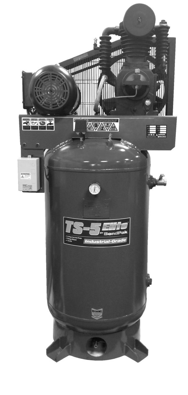
6 V-MAX SERIES DESCRIPTION OF PARTS ON/OFF SWITCH SIDE VIEW On/Off Switch Incoming Power (See Page 7) Service Valve Safety Valve (See Page 7) Pressure Switch NOTE: THIS UNIT CONTAINS NO OIL WHEN SHIPPED. FILL WITH OIL BEFORE OPERATING COMPRESSOR. USE ONLY THIS RECOMMENDED OIL: ISO100, NON-DETERGENT, COMPRESSOR OIL. 6


7 Recommended wire sizes may be larger than the minimum set up by local ordinances. If so, the larger size wire should be used to prevent excessive line voltage drop. The additional wire cost is very small compared with the cost of repairing or replacing a motor electrically starved by the use of supply wires which are too small. 1. Rewire motor per data plate on motor or instruction sheet. 2. Check electric rating of magnetic starter and replace thermal overload elements as required. Improperly grounded electrical components are shock hazards. Make sure all the components are properly grounded to prevent death or serious injury. Improper rotation will result in reduced unit life. The direction of rotation must be counterclockwise while facing the flywheel side of the pump. The motor nameplate will show wiring information for counterclockwise rotation. The proper direction is very important. The direction of rotation on 3 phase motors can be reversed by interchanging any two motor-line leads. This product must be grounded. Grounding reduces the risk of electrical shock by providing an escape wire for the electric current if short circuit occurs. This product must be installed and operated with a power cord or cable that has a grounding wire. GUARDING The belt guard provided must be installed before operating the unit. All moving parts must be guarded. All electrical covers must be installed before turning on the power. DIRECTION OF ROTATION To change to the alternate voltage on three phase motors with 230/460 ratings. The voltage and amperage ratings are listed on the motor nameplate: Pump Fan Counter Clockwise Rotation See Magnetic Starter on page 6 7


8 LUBRICATION THIS UNIT CONTAINS NO OIL WHEN SHIPPED. FILL WITH OIL BEFORE OPERATING COMPRESSOR. Fill to the center of the sight gauge as shown in the image below. Some residual oil may still be in the pump, leaving a thin coat on the sight glass. However, this is not enough oil to operate the unit. Fill pump with single-viscosity, ISO100, non-detergent, compressor oil. AIR TANK SAFETY VALVE If the pressure switch does not shut off the air compressor at its cut-out pressure setting, the safety valve will protect against high pressure by popping off at its factory set pressure (slightly higher than the pressure switch cut-out setting). AIR TANK PRESSURE GAUGE The air tank pressure gauge indicates the reserve air pressure in the air tank. AFTER the first 300 hours, add oil only through the oil fill plug. Pouring oil into any other orifice will cause oil to leak and spray out during operation. Fill to the center of the sight gauge, as shown in the picture below. IMPORTANT: Change oil after first 8 hours of operation. Using any other type of oil may shorten pump life and damage components. The ASME safety valve should also be checked daily. Pull ring on safety valve and allow the ring to snap back to normal position. This valve automatically releases air if the tank pressure exceeds the preset maximum. SIGHT GAUGE PRESSURE SWITCH, START - STOP NOTE: This compressor has a maximum pressure of 175 psi. Do not alter pressure settings on control components above this limit. Do not attempt to tamper or disable the ASME safety valve. The compressor unit starts and stops based on preset pressure switch settings. ON/AUTO-OFF SWITCH LEVER Turn this switch ON to provide automatic power to the pressure switch and OFF to remove power. PRESSURE SWITCH The pressure switch automatically starts the motor when the air tank pressure drops below the factory set cut-in pressure of 140 psi. It stops the motor when the air tank pressure reaches the factory set cutout pressure of 175 psi. If air leaks after the ring has been released, or the valve is stuck and cannot be actuated by the ring, the ASME safety valve must be replaced. If the safety valve does not work properly, over-pressurization may occur causing air tank rupture or explosion. Occasionally pull the ring on the safety valve to make sure that the safety valve operates freely. If the valve is stuck or does not operate smoothly, it must be replaced with a valve having the same pressure rating. DO NOT ADJUST THESE SETTINGS. DOING SO WILL DAMAGE MOTOR AND VOID WARRANTY. 8 RING
.")

9 BREAK-IN PROCEDURES This procedure is required before the air compressor is put into service, before the hose is installed, the check valve is replaced, or a complete compressor pump is replaced. Serious damage may result if the following break-in instructions are not closely followed. Procedure: 1. Make sure the pressure switch lever is in the OFF position. (See image below). OPERATING PROCEDURES Daily Start-Up Checklist 1. Check oil and add if necessary. Do not change oil while compressor is in operation. 2. Before attaching an air hose or accessory, make sure the shut-off valve is in the closed position. Make sure the ON/AUTO lever is in the OFF position. Compressed air from the unit may contain water condensation and oil mist. Do not spray unfiltered air at an item that could be damaged by moisture. Some air tools may require filtered air. Read instructions for air tool or device. Pull Ring SWITCH ON Safety Valve SWITCH OFF 2. Check air compressor wiring. Make sure wires are secure at all terminal connections. 3. Close the tank shut-off valve then open the drain valve fully to permit air to escape and prevent air pressure buildup in the air tank during the break-in period. 3. Attach regulator, hose and accessory. An air pressure regulator, must be installed before using accessories rated at less than 175 psi. Too much air pressure causes a hazardous risk of bursting. Check the manufacturer s maximum pressure rating for air tools and accessories. The regulator outlet pressure must never exceed the maximum pressure rating for the tool or accessory. 4. Place the pressure switch lever in the ON-AUTO position. The motor will stop when air tank pressure reaches cut-out pressure. 5. Open the shut-off valve. 6. If an air pressure regulator is in use, open the regulator by turning it clockwise. Adjust the regulator to the correct pressure setting. Your unit is ready for use. 4. Move the pressure switch lever to ON/AUTO. The compressor will start. 5. Run the air compressor for 30 minutes. Make sure the drain valve is open and there is minimal air pressure build-up in tank. 6. After 30 minutes move the pressure switch lever to the OFF position, check oil and add if necessary. 7. Close the air tank drain valve. 8. Move the pressure switch lever to ON/AUTO. The air receiver will fill to cutout pressure and the motor will stop. Your air compressor is now ready for use. When You Are Finished: 7. Turn the air compressor unit off. 8. Turn the regulator counterclockwise and set the outlet pressure to zero, then remove the air tool or accessory. 9. Open the regulator and allow the air to slowly bleed from the air tank. Close the regulator when air tank pressure is approximately 20 psi. 10. Open the drain valve underneath the air tank and drain water from air tank. If the air compressor is under continuous use, drain at least once each day. If the air compressor is only used occasionally, drain after each use. 11. After water has been drained, close the drain valve. 9

10 DRAIN AIR TANK DAILY. Water will condense in the air tank. If not drained, the water will corrode and weaken the air tank, causing a risk of air tank rupture. The air tank must be drained properly. If the air compressor is under continuous use, drain at least once each day. If the air compressor is only used occasionally, drain after each use. If the tank drain valve is clogged, first release the air pressure in the air tank. The tank drain valve can then be removed, cleaned and reinstalled. MAINTENANCE DANGER SERVICING WHILE PRESSURIZED CAN CAUSE SEVERE INJURY. LOCK OUT SOURCE AND RELIEVE PRESSURE BEFORE SERVICING. Disconnect, tag and lock out power source then release all pressure from the system before attempting to install, service, relocate or perform any maintenance. TANK Drain liquid from tank daily or after each use. The tank should be carefully inspected at a minimum of once a year. Look for cracks forming near the welds. Never attempt to repair or modify a tank! Welding, drilling or any other modification will weaken the tank resulting in damage from rupture or explosion. Always replace worn, cracked or damaged tanks. If a crack is detected, remove pressure from tank immediately and replace. COMPRESSOR LUBRICATION Add oil as required. The oil and should be changed every three months or after every 300 hours of operation; or whichever comes first. If the compressor is run under humid conditions for short periods of time, the humidity will condense in the crankcase and cause the oil to look creamy. Oil contaminated by condensed water will not provide adequate lubrication and must be changed immediately. Using contaminated oil will damage bearings, pistons, cylinders and rings and is not covered under warranty. To avoid water condensation in the oil, periodically run the compressor with tank pressure near 150 psi by opening the tank drain or an air valve connected to the tank or hose. Run the pump for an hour at a time at least once a week or more often if the condensation reoccurs. 10
 must be replaced. Operating compressor with a dirty filter can cause high oil consumption and increase oil contamination in the discharge air.")

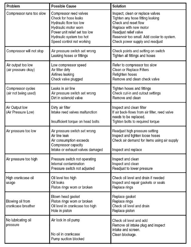
11 AIR FILTER Never run the compressor pump without an intake air filter or with a clogged intake air filter(s). Use compressed air to blow the filters clean. Do not wash or oil the element. If it cannot be blown clean, the filter(s) must be replaced. Operating compressor with a dirty filter can cause high oil consumption and increase oil contamination in the discharge air. INTERCOOLER TUBING Intercooler fins are very sharp. Always wear gloves and use care when you clean or work near the intercooler tubing. Weekly, check the intercooler to be sure all fittings are secure and tight. Blow all dirt, dust and other accumulations from the intercooler fins. COMPONENTS Turn off all power and use light air pressure to blow dust and foreign material from cylinder head, motor, fan blades, air lines, intercooler and tank on a monthly basis. Over tightening the v-belt(s) will result in overloading of the motor and belt failure, while a loose belt will be slipping and resulting in an unstable speed, vibration, overheating the belt and high amp draw. To change tension, loosen the motor hold-down bolts and slide the motor on the base, using a lever if necessary, or by turning the adjusting bolt at the end of the base. Retighten motor hold-down bolts. NOTE: DO NOT OVER TIGHTEN BELTS. Also, align belts using a straight edge against the face of the flywheel and touching the rim on both sides of the face. The belts should be parallel to this straight edge. Dimension A should be the same as B and C to ensure proper alignment of the belts. Slots in the bed-plate allow for sliding the motor back and forth to adjust belt tension. When using an air blow gun always wear eye protection and face mask/respirator. Fast moving air will stir up dust and debris which may be harmful. BELTS The v-belt(s) should be adjusted so that a declination of about 3/8 1/2 inch will be obtained when it is pushed by a finger at the middle point as shown. TROUBLESHOOTING 11
12 12
13 TS-580V-601 PARTS LIST No. DESCRIPTION QTY. No. DESCRIPTION QTY. 1 PUMP 1 12 FLARED JOINT 1 2 MOTOR 1 13 EXHAUST PIPE 1 3 AIR RECEIVER 1 14 AIR RECEIVER 1 4 MAGNETIC SWITCH 1 15 ELBOW 1 5 BALL VALVE 1 16 NIPPLE-M 2 6 NIPPLE 1 17 NIPPLE-F 1 7 PRESSURE SWITCH 1 18 BALL VALVE 1 8 PRESSURE GAUGE 1 19 TAPER-LOCK PULLEY 1 9 UNLOADING ELBOW 1 20 V-BELT 1 10 UNLOADING COPPER PIPE 1 21 BELT GUARD 1 11 CHECK VALVE 1 13
14 14 WATER DRAINAGE


15 OUR UNITS ARE SHIPPED WITH NO OIL. FILL WITH OIL BEFORE STARTING. CHECK THE OIL LEVEL AND QUALITY BEFORE OPERATING THE COMPRESSOR. DO NOT ADD OR CHANGE OIL WHILE COMPRESSOR IS IN OPERATION. USE ONLY THE BELOW RECOMMENDED COMPRESSOR OIL: ISO100, NON-DETERGENT, COMPRESSOR OIL. OIL CHANGING OIL 15
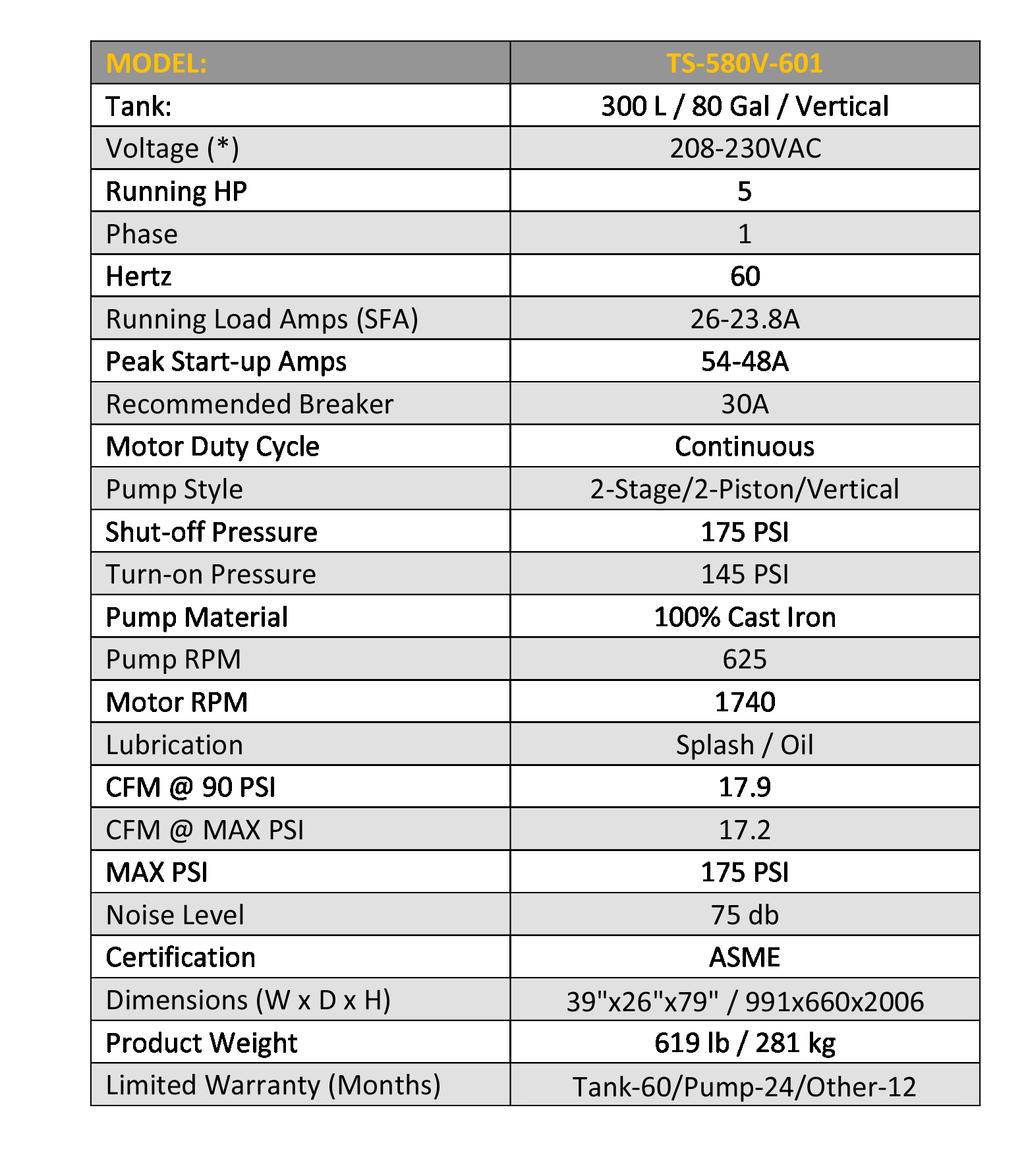

16 SPECIFICATIONS MODEL: TS-580V
17 17
18 MAINTENANCE / INSPECTION RECORDS 18
19 NOTES 19
20
INSTALLATION AND OPERATION MANUAL
 V-MAX ELITE AIR COMPRESSORS - VERTICAL TANK MODEL: 7580V-601 80 Gal. 7580V-603 80 Gal. 10120V-603 120 Gal. PLEASE READ THE ENTIRE CONTENTS OF THIS MANUAL PRIOR TO INSTALLATION AND OPERATION. BY PROCEEDING
AIR COMPRESSOR OPERATING INSTRUCTION AND PARTS LIST
 AIR COMPRESSOR OPERATING INSTRUCTION AND PARTS LIST OIL-LESS TYPE IMPORTANT: PLEASE READ CAREFULLY BEFORE STARTING OPERATIONS. THE CONTENTS ARE FOR GENERAL INFORMATION OF ALL THE SIMILAR MODELS. Record
WHEELED AIR COMPRESSOR AC658HB AC708RB AC908HB AC6520HB. User Manual
 WHEELED AIR COMPRESSOR AC658HB AC708RB AC908HB AC6520HB User Manual table of contents table of contents Introduction 4 Using the Operators Manual Product Identification 5 Record Identification Numbers
AC558RB AC7011RB. operation manual
 AC558RB AC7011RB operation manual table of contents Introduction 4 Using the Operators Manual Specifications 4 Specifications Product Identification 5 Record Identification Numbers Safety 6 Safety Instructions
SPECIFICATIONS Type: Twin stack, single phase Tank: 4 gallon Air Output: PSI; PSI Max PSI: 125 PSI HP: 1.
 2 GALLON TWIN STACK AIR COMPRESSOR Model: 9526 DO NOT RETURN TO STORE. Please CALL 800-348-5004 for parts and service. CALIFORNIA PROPOSITION 65 WARNING: You can create dust when you cut, sand, drill or
FACTORY SERVICED 8 Gallon Air Compressor. Model: Important Safety Instructions RISK OF EXPLOSION OR FIRE:
 FACTORY SERVICED 8 Gallon Air Compressor Model: 42801 90-DAY LIMITED WARRANTY FOR NON-COMMERCIAL USE STOP DO NOT RETURN THIS PRODUCT TO THE RETAILER! Replacement parts: Replacement parts for this tool
3 GALLON, OILLESS PANCAKE COMPRESSOR INSTRUCTIONS. Item #31289
 3 GALLON, OILLESS PANCAKE COMPRESSOR INSTRUCTIONS Item #31289 The EASTWOOD 3 GALLON, OILLESS PANCAKE COMPRESSOR, with an Integral Air Regulator, efficiently supplies all compressed air requirements for
AIR COMPRESSOR. Failure to follow all instructions as listed below may result in electrical shock, fire, and/or serious personal injury.
 2 GALLON AIR COMPRESSOR Model: 7517 DO NOT RETURN TO STORE. Please CALL 800-348-5004 for parts and service. CALIFORNIA PROPOSITION 65 WARNING: You can create dust when you cut, sand, drill or grind materials
2 GALLON TWIN STACK AIR COMPRESSOR W/ HOSE REEL
 2 GALLON TWIN STACK AIR COMPRESSOR W/ HOSE REEL Model: 52024 CALIFORNIA PROPOSITION 65 WARNING: You can create dust when you cut, sand, drill or grind materials such as wood, paint, metal, concrete, cement,
AC1810 / AC1810-A TECHNICAL SPECIFICATIONS. Operating Pressure psi ( kgs/cm²) [AC1810] Displacement. Net Weight
![AC1810 / AC1810-A TECHNICAL SPECIFICATIONS. Operating Pressure psi ( kgs/cm²) [AC1810] Displacement. Net Weight](/thumbs/83/88369739.jpg "AC1810 / AC1810-A TECHNICAL SPECIFICATIONS. Operating Pressure psi ( kgs/cm²) [AC1810] Displacement. Net Weight") Technical Specifications Operating Instructions Maintenance Information Troubleshooting Guide Parts Diagrams AC1810 / AC1810-A THE EVOLUTION OF PERFECTION CAUTION: Before attempting to use or service this
Technical Specifications Operating Instructions Maintenance Information Troubleshooting Guide Parts Diagrams AC1810 / AC1810-A THE EVOLUTION OF PERFECTION CAUTION: Before attempting to use or service this
accidents which arise due to non-observance of these instructions and the safety information herein.
 3 GALLON PANCAKE COMPRESSOR Model: 50959 CALIFORNIA PROPOSITION 65 WARNING: You can create dust when you cut, sand, drill or grind materials such as wood, paint, metal, concrete, cement, or other masonry.
2 GAL AIR COMPRESSOR OPERATOR S MANUAL 1/3HP/2-GALLON IMPORTANT: READ THIS OPERATOR S MANUAL BEFORE USING
 ITEM# AT01101 SKU# 207-1525 OPERATOR S MANUAL 1/3HP/2-GALLON 2 GAL AIR COMPRESSOR IMPORTANT: READ THIS OPERATOR S MANUAL BEFORE USING Toll Free Helpline: 1-888-899-0146 Versions 01 TABLE OF CONTENTS SAFETY
200 PSI FAST-FILL AIR SOURCE KIT
 200 PSI FAST-FILL AIR SOURCE KIT 55% Duty Compressor on 2.0 Gallon Air Tank PART NO. 20007 IMPORTANT: It is essential that you and any other operator of this product read and understand the contents of
TECHNICAL DATA MAINTENANCE AIR COMPRESSOR MODEL G-1
 Dry 131h 1. DESCRIPTION The Viking Model G-1 Maintenance Air Compressor is an electric motor-driven, aircooled, single-stage, oil-less compressor. The unit is equipped with a check valve and provides a
200 PSI HIGH-FLOW AIR SOURCE KIT
 200 PSI HIGH-FLOW AIR SOURCE KIT 50% Duty Compressor on 2.0 Gallon Air Tank PART NO. 20008 IMPORTANT: It is essential that you and any other operator of this product read and understand the contents of
MODEL NUMBER: PSI AIR SOURCE KIT 200 PSI Compressor on 2.0 Gallon 200 PSI Air Tank
 IMPORTANT SAFETY INSTRUCTIONS CAUTION - To reduce risk of electrical shock or Electrocution: MODEL NUMBER: 20008 200 PSI AIR SOURCE KIT 200 PSI Compressor on 2.0 Gallon 200 PSI Air Tank IMPORTANT: It is
Portable Oil Lube Air Compressors
 Portable Oil Lube Air Compressors 8003631 8003632 0410149 8018968 8018940 Owner s Manual Read and understand operating instructions before use Safety definitions The information listed below should be
General Safety. All electrical work
 Operating Instructions Extreme Contractor Air Compressor Models Please read and save these instructions. Read carefully before attempting to assemble, install, operate or maintain the product described.
MODEL NUMBER: M20005 AIR SOURCE KIT. 30% Duty Compressor on. 2.0 Gallon Air Tank SAVE THIS MANUAL FOR FUTURE REFERENCE
 MODEL NUMBER: M20005 AIR SOURCE KIT 30% Duty Compressor on 2.0 Gallon Air Tank SAVE THIS MANUAL FOR FUTURE REFERENCE USER MANUAL IMPORTANT SAFETY INSTRUCTIONS CAUTION - To reduce risk of electrical shock
Part IV: Troubleshooting
 Part IV: Troubleshooting Excessive Oil Carryover Pump-Up Time Test Excessive oil carryover can have adverse effects on the performance of pneumatic climate control systems. Although some oil entrainment
PC 1010 Electric Air Compressor
 PC 1010 Electric Air Compressor Operating Instructions Warnings for the safe use of this compressor are included in this manual. TABLE OF CONTENTS INTRODUCTION... 3 SAFETY INSTRUCTIONS...3 INSPECTION...
444C DUAL PERFORMANCE VALUE PACK
 (Chrome) PART NO. 44432 IMPORTANT: It is essential that you and any other operator of this product read and understand the contents of this manual before installing and using this product. SAVE THIS MANUAL
42045 Heavy Duty ADA Base Model Kit: 85/105 PSI (ADA Compressor Only) Heavy Duty ADA Base Model Kit: 110/145 PSI (ADA Compressor Only)
 Heavy Duty ADA Base Model Kit: 110/145 PSI (ADA Compressor Only)") 42045 Heavy Duty ADA Base Model Kit: 85/105 PSI (ADA Compressor Only) 42047 Heavy Duty ADA Base Model Kit: 110/145 PSI (ADA Compressor Only) 45052 Constant Duty ADA Base Model Kit: 85/105 PSI (ADA Compressor
42045 Heavy Duty ADA Base Model Kit: 85/105 PSI (ADA Compressor Only) 42047 Heavy Duty ADA Base Model Kit: 110/145 PSI (ADA Compressor Only) 45052 Constant Duty ADA Base Model Kit: 85/105 PSI (ADA Compressor
200 PSI COMPRESSORS - MODEL NUMBERS
 200 PSI COMPRESSORS - MODEL NUMBERS 380C AIR COMPRESSOR KIT PART NO. 38033 480C AIR COMPRESSOR KIT PART NO. 48043 380C 480C IMPORTANT: It is essential that you and any other operator of this product read
400C & 450C DUAL PERFORMANCE VALUE PACKS
 (Chrome) PART NO. 40013 (Silver) PART NO. 45012 (Chrome) PART NO. 45013 IMPORTANT: It is essential that you and any other operator of this product read and understand the contents of this manual before
97C COMPRESSOR KIT 12V PART NO C COMPRESSOR KIT 24V PART NO C COMPRESSOR KIT PART NO
 97C COMPRESSOR KIT 12V PART NO. 00097 97C COMPRESSOR KIT 24V PART NO. 02497 98C COMPRESSOR KIT PART NO. 00098 97C 98C IMPORTANT: It is essential that you and any other operator of this product read and
100C Air Compressor Kit
 10010 100C Air Compressor (standard mounting bracket, CE Spec) 10014 100C Air Compressor (no leader hose or check valve, CE Spec) 10016 100C Air Compressor (with Omega Bracket, CE Spec) IMPORTANT: It is
IMPORTANT SAFETY INSTRUCTIONS
 IMPORTANT SAFETY INSTRUCTIONS CAUTION - To reduce risk of electrical shock: - Do not disassemble. Do not attempt repairs or modifications. Refer to qualified service agencies for all service and repairs.
420C AIR COMPRESSOR KIT PART NO C AIR COMPRESSOR KIT PART NO
 420C AIR COMPRESSOR KIT PART NO. 42042 460C AIR COMPRESSOR KIT PART NO. 46043 420C 460C IMPORTANT: It is essential that you and any other operator of this product read and understand the contents of this
250C-IG COMPRESSOR KIT 12V PART NO C-IG COMPRESSOR KIT 24V PART NO
 250C-IG COMPRESSOR KIT 12V PART NO. 25050 250C-IG COMPRESSOR KIT 24V PART NO. 25058 IMPORTANT: It is essential that you and any other operator of this product read and understand the contents of this manual
3/8" Dr. Air Butterfly Impact Wrench
 8192106 3/8" Dr. Air Butterfly Impact Wrench Owner s Manual Read and understand all instructions before use. Retain this manual for future reference. Specifications Construction: Polished aluminum and
120 PSI FAST-FILL AIR SOURCE KIT 25% Duty Compressor on 1.5 Gallon Air Tank
 120 PSI FAST-FILL AIR SOURCE KIT 25% Duty Compressor on 1.5 Gallon Air Tank PART NO. 20003 IMPORTANT: It is essential that you and any other operator of this product read and understand the contents of
400H HARDMOUNT AIR COMPRESSOR KIT PART NO H HARDMOUNT AIR COMPRESSOR KIT PART NO
 400H HARDMOUNT AIR COMPRESSOR KIT PART NO. 40042 450H HARDMOUNT AIR COMPRESSOR KIT PART NO. 45042 400H 450H IMPORTANT: It is essential that you and any other operator of this product read and understand
DeVILBISS AIR POWER COMPANY. OWNERS MANUAL FOR PERMANENTLY LUBRICATED AIR COMPRESSOR (For Home Use Only) MODEL NO. DFAC153 SPECIFICATION CHART
 MODEL NO. DFAC153 SPECIFICATION CHART") DeVILBISS AIR POWER COMPANY OWNERS MANUAL FOR PERMANENTLY LUBRICATED AIR COMPRESSOR (For Home Use Only) MODEL NO. DFAC153 SPECIFICATION CHART Model No. Horsepower SCFM @ 40 psig SCFM @ 90 psig Cut-In Cut-Out
DeVILBISS AIR POWER COMPANY OWNERS MANUAL FOR PERMANENTLY LUBRICATED AIR COMPRESSOR (For Home Use Only) MODEL NO. DFAC153 SPECIFICATION CHART Model No. Horsepower SCFM @ 40 psig SCFM @ 90 psig Cut-In Cut-Out
250C-IG COMPRESSOR KIT 12V PART NO C-IG COMPRESSOR KIT 24V PART NO
 250C-IG COMPRESSOR KIT 12V PART NO. 25050 250C-IG COMPRESSOR KIT 24V PART NO. 25058 IMPORTANT: It is essential that you and any other operator of this product read and understand the contents of this manual
OPERATOR S MANUAL 1.5 HP/6-GALLON 6 GAL AIR COMPRESSOR IMPORTANT: READ OPERATOR S MANUAL BEFORE USING. Toll Free Helpline:
 ITEM# 0306 SKU# 07-55 OPERATOR S MANUAL.5 HP/6-GALLON 6 GAL AIR COMPRESSOR IMPORTANT: READ OPERATOR S MANUAL BEFORE USING Toll Free Helpline: -888-899-06 VY03A36669 TABLE OF CONTENTS Specifications------------------------------------------------------------------------------------------------
Model PSI Compressor with 3-Gallon Air Tank 12VDC
 Model 6350 150 PSI Compressor with 3-Gallon Air Tank 12VDC IMPORTANT: It is essential that you and any other operator of this product read and understandd the contents of this manual before installing
450P AUTOMATIC PORTABLE COMPRESSOR EXTREME SERIES
 EXTREME SERIES PART NO. 45043 IMPORTANT: It is essential that you and any other operator of this product read and understand the contents of this manual before installing and using this product. SAVE THIS
SPECIFICATIONS TABLE Maximum Air Pressure 115 PSI Air Tank Capacity 20 Gallons
 SPECIFICATIONS TABLE Maximum Air Pressure 115 PSI Air Tank Capacity 20 Gallons Air Flow Capacity 6.2 CFM at 40 PSI 5.2 CFM at 90 PSI Motor 2.5 HP Working / 4 HP Peak 120 Volt / 60 Hz / 13 A / 1-Phase Required
SC6H OIL-LESS AIR COMPRESSOR
 SC6H OIL-LESS AIR COMPRESSOR OWNER S MANUAL FOR YOUR SAFETY PLEASE READ THESE INSTRUCTIONS CAREFULLY AND RETAIN THEM FOR FUTURE USE. MAIN COMPONENTS 1. ON/OFF switch 2. Outlet valve 3. Regulating valve
8-gallon Air Compressor. Owner s Manual
 8-gallon Air Compressor 58-7914-8 Owner s Manual If any parts are missing or damaged, or if you have any questions concerning this product, please contact the toll-free helpline, at 1-800-689-9928 6106-0170-03
LUBRICATOR ASSEMBLY AND OPERATING INSTRUCTIONS
 AIR FILTER, REGULATOR AND LUBRICATOR 4035 ASSEMBLY AND OPERATING INSTRUCTIONS 349 Mission Oaks Blvd., Camarillo, CA 930 Visit our Web site at http://www.harborfreight.com Copyright 004 by Harbor Freight
1 DRIVE INDUSTRIAL IMPACT WRENCH
 1 DRIVE INDUSTRIAL IMPACT WRENCH 92622 ASSEMBLY AND OPERATING INSTRUCTIONS 3491 Mission Oaks Blvd., Camarillo, CA 93011 Visit our Web site at http://www.harborfreight.com Copyright 2004 by Harbor Freight
450P- RV AUTOMATIC PORTABLE COMPRESSOR EXTREME SERIES
 450P- RV AUTOMATIC PORTABLE COMPRESSOR EXTREME SERIES PART NO. 45053 IMPORTANT: It is essential that you and any other operator of this product read and understand the contents of this manual before installing
Operating Instructions and Parts Manual 24529
 Please read and save these instructions. Read through this owner s manual carefully before using product. Protect yourself and others by observing all safety information, warnings, and cautions. Failure
accidents which arise due to non-observance of these instructions and the safety information herein. SPECIFICATIONS
 18 GAUGE 1-1/4 INCH BRAD NAILER Model: 7611 CALIFORNIA PROPOSITION 65 WARNING: You can create dust when you cut, sand, drill or grind materials such as wood, paint, metal, concrete, cement, or other masonry.
1 HP / 1.6 GALLON AIR COMPRESSOR OPERATING MANUAL
 1 HP / 1.6 GALLON AIR COMPRESSOR OPERATING MANUAL Item # 123005 READ ALL INSTRUCTIONS BEFORE OPERATING SAVE THESE INSTRUCTIONS Thank you for purchasing your Northern Industrial TM Air Compressor. Before
OWNER S MANUAL. Page: 1 of 8
 Air Needle Scaler OWNER S MANUAL WARNING: Read carefully and understand all INSTRUCTIONS before operating. Failure to follow the safety rules and other basic safety precautions may result in serious personal
INTENDED USE TECHNICAL SPECIFICATIONS
 1/2IN. HEAVY-DUTY AIR IMPACT WRENCH OWNER S MANUAL WARNING: Read carefully and understand all INSTRUCTIONS before operating. Failure to follow the safety rules and other basic safety precautions may result
SSFU SUPER SPRAYFAST UNIVERSAL ADHESIVE APPLICATOR
 S S F U SSFU SUPER SPRAYFAST UNIVERSAL ADHESIVE APPLICATOR MACHINERY DIVISION OWNER S MANUAL UNIT INSTRUCTIONS Please follow all SSFU Safety Instructions. Contact your Duro Dyne Tech Service if you have
20 GAL OIL FREE AIR COMPRESSOR
 ot n fo rr ep ro du ct io 20 GAL OIL FREE AIR COMPRESSOR N Product Model # 074064-00 Manual # 8008808 Revision: A Read and understand this operator's manual thoroughly before using the product. It contains
RIX COMPRESSORS. MICROBOOST Owner s Manual CONFIGURATION A MB-115 MB-230. November 21, 2002 APPLICABILITY [ A]
![RIX COMPRESSORS. MICROBOOST Owner s Manual CONFIGURATION A MB-115 MB-230. November 21, 2002 APPLICABILITY [ A]](/thumbs/77/74792841.jpg "RIX COMPRESSORS. MICROBOOST Owner s Manual CONFIGURATION A MB-115 MB-230. November 21, 2002 APPLICABILITY [ A]") RIX COMPRESSORS MICROBOOST Owner s Manual CONFIGURATION A MB-115 MB-230 November 21, 2002 APPLICABILITY [ A] INTRODUCTION Safety This electromechanical equipment is designed to produce high pressure gas.
RIX COMPRESSORS MICROBOOST Owner s Manual CONFIGURATION A MB-115 MB-230 November 21, 2002 APPLICABILITY [ A] INTRODUCTION Safety This electromechanical equipment is designed to produce high pressure gas.
APCO ARV CLEAN WATER AIR RELEASE VALVES. Model 50A
 APCO ARV CLEAN WATER AIR RELEASE VALVES Model 50A Instruction D12013 February 2017 Instructions These instructions provide installation, operation and maintenance information for APCO ARV Clean Water Air
Composite Pistol-Type Air Needle Scaler OWNER S MANUAL
 Composite Pistol-Type Air Needle Scaler OWNER S MANUAL WARNING: Read carefully and understand all INSTRUCTIONS before operating. Failure to follow the safety rules and other basic safety precautions may
20 Gallon Air Compressor
 0 Gallon Air Compressor Model: 540 *Actual product may vary slightly 880540 0/04 CALIFORNIA PROPOSITION 65 WARNING: You can create dust when you cut, sand, drill or grind materials such as wood, paint,
accidents which arise due to non-observance of these instructions and the safety information herein. SPECIFICATIONS
 18 GAUGE 2 INCH BRAD NAILER Model: 7555 CALIFORNIA PROPOSITION 65 WARNING: You can create dust when you cut, sand, drill or grind materials such as wood, paint, metal, concrete, cement, or other masonry.
2 Gallon Oil Free Air Compressor
 2 Gallon Oil Free Air Compressor Item# 22020 Owner s Manual DO NOT RETURN TO STORE Questions? Problems? Please call our customer help line: (800) 232-1195 M-F 8-5 CST Or by email: partsandservice@greatlakestec.com
AIR INLINE METAL SHEAR
 AIR INLINE METAL SHEAR ASSEMBLY and OPERATING INSTRUCTIONS 3491 Mission Oaks Blvd. / Camarillo, CA 93011 Copyright 1997 by Harbor Freight Tools. All rights reserved. No portion of this manual or any artwork
2.5 & 5.0 GALLON PRESSURE TANKS
 2.5 & 5.0 GALLON PRESSURE TANKS Includes: MODEL 7025 MODEL 7026 MODEL 7027 MODEL 7028 2.5 Gallon Single Regulation (NON A.S.M.E.) 2.5 Gallon Dual Regulation (NON A.S.M.E.) 5.0 Gallon Single Regulation
80 GALLON INDUSTRIAL AIR COMPRESSOR OPERATOR'S MANUAL
 80 GALLON INDUSTRIAL AIR COMPRESSOR OPERATOR'S MANUAL CAUTION RISK OF INJURY! READ ENTIRE MANUAL BEFORE OPERATING! THIS MANUAL IS AN IMPORTANT PART OF THE AIR COMPRESSOR AND MUST REMAIN WITH THIS UNIT!
Freedom8 ShoeBox Compressor Manual
 Freedom8 ShoeBox Compressor Manual Warning!! This product is not a toy! Use or misuse can cause severe injury or death! Use only with adult supervision. This unit is only to be used with tanks, hoses and
480C DUAL PERFORMANCE VALUE PACK
 (Pewter) PART NO. 48012 (Chrome) PART NO. 48032 (Stealth Black) PART NO. 48042 IMPORTANT: It is essential that you and any other operator of this product read and understand the contents of this manual
Side Stack Compressor. Instruction manual ESPAÑOL: PÁGINA 23 FRANÇAISE : PAGE 45 MODEL CPF23400S
 ESPAÑOL: PÁGINA 23 FRANÇAISE : PAGE 45 Instruction manual Side Stack Compressor MODEL CPF23400S To learn more about Porter-Cable visit our website at: http://www.porter-cable.com IMPORTANT Please make
DANGER! Breathable Air Warning DISCLAIMER OF WARRANTIES
 DANGER! Breathable Air Warning This compressor/pump is NOT equipped and should NOT be used as is to supply breathing quality air. For any application of air for human consumption, you must fit the air
MODEL NUMBER: P PORTABLE COMPRESSOR
 MODEL NUMBER: 30033-300P PORTABLE COMPRESSOR IMPORTANT: It is essential that you and any other operator of the product read and understand the contents of this manual before installing and using this product.
MODEL NUMBER: P PORTABLE COMPRESSOR
 MODEL NUMBER: 44043-440P PORTABLE COMPRESSOR IMPORTANT: It is essential that you and any other operator of the product read and understand the contents of this manual before installing and using this product.
TEM# Air Hammer Combo USER'S MANUAL
 Air Tools TEM# 40 Air Hammer Combo USER'S MANUAL Read carefully and understand RULES FOR SAFE OPERATION and instructions before operating. Failure to follow the safety rules and other basic safety precautions
Instruction manual. Direct Drive Oil Lube Portable Air Compressor ESPAÑOL: PÁGINA 27 FRANÇAIS: PAGE 53. Model C3550
 Instruction manual ESPAÑOL: PÁGINA 27 FRANÇAIS: PAGE 53 Model C3550 Direct Drive Oil Lube Portable Air Compressor To learn more about Porter-Cable visit our website at: http://www.porter-cable.com IMPORTANT
Instruction manual. Pancake Compressor ESPAÑOL: PÁGINA 19 FRANÇAISE: PAGE 37 MODEL CPF23400P
 ESPAÑOL: PÁGINA 19 FRANÇAISE: PAGE 37 Instruction manual Pancake Compressor MODEL CPF23400P To learn more about Porter-Cable visit our website at: http://www.porter-cable.com IMPORTANT Please make certain
MODEL NUMBER: P-A AUTOMATIC PORTABLE COMPRESSOR
 MODEL NUMBER: 45043-450P-A AUTOMATIC PORTABLE COMPRESSOR IMPORTANT: It is essential that you and any other operator of the product read and understand the contents of this manual before installing and
Right-Angle Tube Roller Model
 SPECIFICATIONS Model no. Free Speed (RPM) Throttle Rotation Max. Torque Ft-Lb Air Pressure psi Air Inlet Hose Air Flow @Free Speed Spindle Weight 909-1700 95 Lever type Reversible 240 90 1/2 NPT 1/2 I.D.
2 HP / 4 GALLON AIR COMPRESSOR OPERATING MANUAL
 2 HP / 4 GALLON AIR COMPRESSOR OPERATING MANUAL Item # 123006 READ ALL INSTRUCTIONS BEFORE OPERATING SAVE THESE INSTRUCTIONS Thank you for purchasing your Northern Industrial TM Air Compressor. Before
Oil-Free Air Compressor
 INSTRUCTION MANUAL Oil-Free Air Compressor (CP200) PART NO. D27930 Rev.0 Copyright 2002 Delta Machinery To learn more about DELTA MACHINERY visit our website at: www.deltamachinery.com. For Parts, Service,
PC 2001 Electric Air Compressor
 Questions? Comments? call SENCO S toll-free Action-line: 1-888-222-8144 or, e-mail: toolprof@senco.com PC 2001 Electric Air Compressor Operating Instructions Document #FN2001 Issued 5/30/A Warnings for
24L OIL FREE AIR COMPRESSOR MODEL NO: TIGER 7/250 PART NO: OPERATION & MAINTENANCE INSTRUCTIONS LS10/13
 24L OIL FREE AIR COMPRESSOR MODEL NO: TIGER 7/250 PART NO: 2244030 OPERATION & MAINTENANCE INSTRUCTIONS LS10/13 INTRODUCTION Thank you for purchasing this product. Before attempting to use this product,
RARS5000 AIR BODY SAW OWNER S OPERATING MANUAL
 RARS5000 AIR BODY SAW OWNER S OPERATING MANUAL DESCRIPTION 1. No mar 2. No mar tip 3. Housing grip 4. Trigger 5. Air inlet 6. Air inlet plug 7. Plastic board Important! It is essential that you read the
Bray/ VAAS O-Ported Series Knife Gate Valve 770/780 Series Operation and Maintenance Manual
 Bray/ VAAS Knife Gate Valve 770/780 Series Operations and Maintenance Manual Table of Contents Definition of Terms 1 Safety Instructions 1 Introduction 2 Unpacking 2 Storage 2 Installation 2 Commissioning
HEAVY-DUTY AIR RATCHET WRENCH OWNER S MANUAL
 HEAVY-DUTY AIR RATCHET WRENCH OWNER S MANUAL WARNING: Read carefully and understand all INSTRUCTIONS before operating. Failure to follow the safety rules and other basic safety precautions may result in
IMPORTANT SAFETY INSTRUCTIONS
 IMPORTANT SAFETY INSTRUCTIONS CAUTION - To reduce risk of electrical shock or electrocution: - Do not disassemble. Do not attempt repairs or modifications. Refer to qualified service agencies for all service
VERTICAL AIR COMPRESSORS
 VERTICAL AIR COMPRESSORS MODEL NO: VE11C150, VE15C150, VE18C150 PART NO: 2226005, 2226000, 2226015 OPERATION & MAINTENANCE INSTRUCTIONS LS0615 INTRODUCTION Thank you for purchasing this CLARKE Vertical
EGL-12 OIL-LESS COMPRESSOR
 Operator s Manual 2016 EGL-12 OIL-LESS COMPRESSOR EGL-12 / 2HP OIL-LESS COMPRESSOR INSTALLATION QUESTIONS? 1-800-240-5677 SIERRA DENTAL PRODUCTS, LLC. 1953 W. Gulf to Lake Hwy. Lecanto, FL 34461 www.dentalvacuums.com
2 Gallon Air Compressor
 Table of Contents Topic Page 2 Gallon Air Compressor Safety Guidelines-Definitions 4 Hazard Warnings 5 Air Compressor 15 Precautions 15 Basic Air Compressor Components 16 Assembling the Air Compressor
PC1131 Electric Air Compressor
 Senco Products Inc. 8485 Broadwell Road Cincinnati, Ohio 45244 PC1131 Electric Air Compressor Operating Instructions C US 2006, 2007 by Senco Products, Inc. Warnings for the safe use of this tool are included
R E D I C O N T R O L S
 R E D I C O N T R O L S Operation & Maintenance Manual Portable Service Purger for Low Pressure Chillers Model: PSP-LP-1B For Refrigerants R-11, R-113, R-114 & R-123 & Other Similar Refrigerants File Literature
Air Compressor Electric Handheld
 TASK FORCE Item #8369 Air Compressor Electric Handheld 2 gallons 00 max psi 20 VAC -- 5 amp minimum circuit Includes: 25 ft nylon coil hose and 7 pc accessory kit OWNER'S MANUAL and Parts List For customer
HPB25 Hydraulic Paving Breaker
 INSTRUCTION MANUAL HPB25 Hydraulic Paving Breaker Read and understand all of the instructions and safety information in this manual before operating or servicing this tool. Register this product at www.greenlee.com
AIR/OVER HYDRAULIC JACK 20 TON
 AIR/OVER HYDRAULIC JACK 0 TON 4487 ASSEMBLY AND OPERATING INSTRUCTIONS 349 Mission Oaks Blvd., Camarillo, CA 930 Visit our Web site at http://www.harborfreight.com Copyright 999 by Harbor Freight Tools.
Budget Range Operators Handbook
 Budget Range Operators Handbook BAMBI AIR COMPRESSORS LTD 152 Thimble Mill Lane Heartlands Birmingham B7 5HT United Kingdom Tel: 0121 322 2299 Fax: 0121 322 2297 Email: sales@bambi-air.co.uk www.bambi-air.co.uk
VERTICAL AIR COMPRESSORS
 VERTICAL AIR COMPRESSORS MODEL NO: VE15C150, VE18C150, VE25C150 PART NO: 2226010, 2226020, 2226025 OPERATION & MAINTENANCE INSTRUCTIONS LS0715 INTRODUCTION Thank you for purchasing this CLARKE Vertical
OILLESS AIR COMPRESSOR 135 PSI
 OILLESS AIR COMPRESSOR 135 PSI Model 96087 Assembly And Operation Instructions Please note: Air Hose sold separately. Due to continuing improvements, actual product may differ slightly from the product
Installation and Service Manual
 An Actuant Company Installation and Service Manual Heavy Duty Hydraulic Stabilization Legs CONTENTS Part # 3010003129 REV 0D Section Page 1.0 Receiving Instructions 2 2.0 Safety Issues 2 3.0 Hydraulic
Marschalk Model # 94000
 Marschalk Model # 94000 12-volt DC Portable oil-less Air Compressor Operation Manual 27250006 REV 1 9/13/05 Table of Contents CHAPTER 1: SYSTEM DESCRIPTION... 5 FUNCTION AND THEORY... 5 SYSTEM COMPONENTS...
PC 1010 Electric Air Compressor
 Questions? Comments? call SENCOíS toll-free Action-line: 1-888-222-8144 or e-mail: toolprof@senco.com PC 1010 Electric Air Compressor Senco Products, Inc. 8485 Broadwell Rd. Cincinnati, OH 45244 Operating
Pressure Relief Valve Instruction Manual
 CVR3-M0_062017 Pressure Relief Valve Instruction Manual MODEL: CVR3 SFA Companies 10939 N. Pomona Ave. Kansas City, MO 64153 Tel: 888-332-6419 * Fax: 816-448-2142 E-mail: sales@bvahydraulics.com Website:
AIR COMPRESSOR OPERATING INSTRUCTION AND PARTS LIST DIRECT TYPE IMPORTANT:
 TABLE OF CONTENTS PAGE AIR COMPRESSOR 1:IMPORTANT SAFETY INSTRUCTION 3-4 2:GENERAL DESCRIPTION 5 3:ON RECEIPT INSPECTION 5 OPERATING INSTRUCTION AND PARTS LIST 4:GENERAL REQUIREMENT 5 5:INSTALLATION 5-7
General No. 25 and D-25 Handy Operating Instructions
 General No. 25 and D-25 Handy For 1-1/4 through 3 lines (30mm 75mm) No. 25 Handy D- 25 Handy This tool is designed to give you years of trouble-free, profitable service. However, no machine is better than
ULTRA-LIGHT DUTY ONBOARD AIR SYSTEM
 ULTRA-LIGHT DUTY ONBOARD AIR SYSTEM PART NO. 10000 IMPORTANT: It is essential that you and any other operator of this product read and understand the contents of this manual before installing and using
 RT3 CAP NAILER OWNER S MANUAL Operation Safety Maintenance Warranty! www.stingerworld.com PLEASE READ! This manual contains important information about product safety. REV 09/14 WELCOME TO STINGER Congratulations
Installation Instructions Air Compressor Part # 2780, 2781
 Note: It is essential that the operator of this product read and understand the contents of this manual before installing and using this product. Parts Included Qty Parts Included Qty Compressor 1 Coil
FAILURE TO COMPLY WITH INSTRUCTIONS IN THIS MANUAL COULD RESULT IN THE VOIDING OF YOUR WARRANTY, AND PERSONAL INJURY, AND/OR PROPERTY DAMAGE
 Owners Manual Check www.compressed-air-systems.com for most up to date manual and compressor service and technical information CAUTION READ THIS MANUAL CAREFULLY before operating or servicing this air