STRENGTH CALCULATIONS AND SOLIDITY SURVEY OF TONISCO HOT TAPPING GAS VALVES
|
|
|
- Sherilyn Stevenson
- 5 years ago
- Views:
Transcription


1 STRENGTH CALCULATIONS AND SOLIDITY SURVEY OF TONISCO HOT TAPPING GAS VALVES Christian Hackmann Bachelor s thesis May 2014 Environmental Engineering
2 ABSTRACT Tampereen ammattikorkeakoulu Tampere University of Applied Sciences Environmental Engineering CHRISTIAN HACKMANN: Strength Calculations and Solidity Survey of TONISCO Hot Tapping Gas Valves Bachelor's thesis 83 pages, appendices 10 pages May 2014 The aim of this bachelor thesis was to implement a solidity survey and strength calculations of TONISCO hot tapping gas valves under the support of ANSYS workbench and with conservative hand calculations as far as possible. The TONISCO hot tapping gas valves are available in DN50, DN80 and DN100 and therefore every valve has to be proven according to its solidity. For the most appropriate solution the manufacturer also has to apply some main principles. The manufacturer has to eliminate or to reduce hazards as far as is reasonably possible, to apply appropriate protection measures against hazards which are not possible to eliminate and where appropriate, to inform users of residual hazards to reduce all risks. During the implementation of this Project, I used methods such as conservative calculations according to standards and simulations supported by software. Delivered data by the simulations were evaluated, used for further calculations and discussed. The simulations were done for worst case conditions and can be seen as a approximation of the reality. As a result I found out that the TONISCO hot tapping gas valves can be seen as safe for a use under a pressure of PN10 in all cases. The TONISO hot tapping gas valves DN80 and DN50 can even be seen as safe for PN16. Key words: Pressure Equipment Directive, Hot Tapping, FEM, Finite Element Method, ANSYS Workbench, Strength Calculations, Solidity Survey
3 3 CONTENTS 1 INTRODUCTION ABOUT TONISCO About Hot Tapping About TONISCO Hot Tapping TONISCO Drilling Devices and Hot Tapping Valves Remaining Products and Services ABOUT HOT TAPPING WITH THE TONISCO HOT TAPPING GAS VALVES The TONISCO Hot Tapping Gas Valves TONISCO Hot Tapping Method with the TONISCO Hot Tapping Gas Valves STANDARDS AND REGULATIONS Pressure Equipment Directive Other Standards Categorization According to the Pressure Equipment Directive Pressure Equipment Directive ANNEX I ANNEX II MAIN ASSUMPTIONS Material Welding SOLIDITY SURVEY AND STRENGH CALCULATIONS Theoretical Background Equivalent Stress Simplifications Equivalent Stresses of the Valves Equivalent Stress DN Equivalent Stress DN Equivalent Stress DN Stresses According to the AD 2000 Regulations Stress according AD 2000 in DN50 Valve Stress according AD 2000 in DN80 Valve Stress according AD 2000 in DN100 Valve Conclusion Weakest Point STRENGH SURVEY SUPPORTED BY SOFTWARE... 38
4 4 7.1 About the use of CAD About the use of FEM LOAD CASES Implementation of Case Implementation of Case Implementation of Case Axial Forces RESULTS OF THE LOAD CASES Example (DN100, 25 bar) Case Case Case Results 0-40 bar DN DN DN CONCLUSION DISCUSSION AND CHALLENGES Discussion Challenges REFERENCES APPENDICES Appendix 1. Modelling of the Welding Appendix 2. Simplifications Appendix 3. Datasheets for TONISCO hot tapping gas valves... 88
5 5 ABBREVIATIONS AND TERMS PED AD PS TS DN PN CAD FEM FEA R p, σ F R pn R mn f w d i d o F E p σexisting σallowed σexisting, welding σallowed, welding σa σc σr σeq σmax σmin σc, max σr, min σeq, max Pressure Equipment Directive Arbeitsgemeinschaft Druckbehälter Maximum allowable pressure [bar] Maximum allowable temperature [ C] Nominal pipe size Pressure nominal Computer aided design Finite Element Method Finite Element Analysis Yield strength [N/mm², MPa] Yield strength nominal [N/mm², MPa] Tensile ultimate strength [N/mm², MPa] Joint coefficient Inside diameter [mm] Outside diameter [mm] Force [N] Young s modulus [N/mm², MPa] Pressure [bar] Existing stress [N/mm², MPa] Allowed stress [N/mm², MPa] Existing stress in welding [N/mm², MPa] Allowed stress in welding [N/mm², MPa] Axial stress [N/mm², MPa] Circumferential stress [N/mm², MPa] Radial stress [N/mm², MPa] Equivalent stress [N/mm², MPa] Maximum stress [N/mm², MPa] Minimum stress [N/mm², MPa] Maximum circumferential stress [N/mm², MPa] Minimum radial stress [N/mm², MPa] Maximum equivalent Stress [N/mm², MPa]
6 6 σeq, average σc, average σr, average ɛ Tot ɛ pl ɛ el S s c 1 c 2 Average equivalent stress [N/mm², MPa] Average circumferential stress [N/mm², MPa] Average radial stress [N/mm², MPa] Total strain [mm] Plastic strain [mm] Elastic strain [mm] Safety factor Thickness of the wall of the valve [mm] Surcharge for deviation in manufacturing [mm] Surcharge for wear [mm]
7 7 1 INTRODUCTION Since all kinds of pressure equipment represent a high hazard because of high internal pressure that can lead to accidents and disasters, there is a need to prove that the equipment can be used safely. Generally the involved risks should be avoided beforehand. In order to avert all possible risks, standards like the Pressure Equipment Directive were developed to keep the handling of pressure equipment as safe as possible. According to the Pressure Equipment Directive there are several ways to prove the sufficient safety of pressure equipment. In general the use of formulas and conservative hand calculations are a commonly used tool in mechanical engineering. Over the years the used equations were developed to implement a high safety standard in all fields of mechanical engineering. With formulas and hand calculations it is not always possible to consider difficult geometries and stress peaks which often occur. Because of the technological progress nowadays the software supported simulation with the Finite Element Method is a commonly used tool in mechanical engineering to determine the stresses in parts under load. Stress peaks become visible and can be evaluated correctly by the leading engineers. Therefore the use of such simulation methods can be seen as a responsible and reasonable way for solidity surveys for parts in all fields of mechanical engineering. But such simulation methods also contain some risks. Since the software supported FEM simulation is just an approximation of the reality every step like the fixed supports, the loads and the results has to be interpreted correctly by the engineer.
8 8 2 ABOUT TONISCO TONISCO Systems is a Finnish company founded in Tampere in 1969 with the main target to offer devices for the extension of any kind of pipe system. In the beginning the main business of the company was the developing of innovative drilling devices and attachments which should be manufactured by other companies. After a couple of years also the production of the drilling devices and the attachments was accomplished by TONISCO to ensure a consistent, high quality standard. In the first ten years TONISCO delivered their devices and attachments exclusively to customers in Finland. Because there was a high demand for hot tapping systems also in other countries, TONISCO started to export their innovative solutions to neighboring countries and overtime to other European countries and countries all over the world. In 2007 about 80% of the whole production was exported out of Finland. Today TONISCO is delivering their devices, attachments and services to 20 different countries directly or representatively. Until 2007 more than TONISCO hot tapping valves and more than 1700 hot tapping drilling devices were delivered successfully. One of the first hot tapping drilling devices was driven by a combustion engine. It was developed to connect customers to the drinking water system. With that Drilling-Device it was possible to carry out hot tappings in sizes from DN50 to DN200. A combustion engine was used because electricity was not usually expected at construction sites in the past. Later TONISCO developed Drilling-Devices with which hot tappings on every usual material were made possible (for instance plastic, steel and ferroconcrete). The devices were be able to be driven electrically, manually, hydraulically or pneumatically. Because of the processing with several different materials, suitable connection components, drill bits and hole saws were required, technical knowledge was won through years of experience. This knowledge helps to develop new devices and to select the right materials for new innovative solutions in hot tapping.(tonisco. 2014a.)
9 9 2.1 About Hot Tapping Hot tapping is a way to create branches of pipes and pipe systems. It is mostly used to extend pipe systems without stopping the running system. All drillings and welds are done while there is pressure in the running system. The advantage of the method is that there is no need to stop the process and therefore there is no disruption to the process or production. This reduces the potential loss of money. To run through a successful hot tapping process, drilling and welding abilities are required. Target systems in the industry of hot tapping are for instance cooling systems, district heating, gas and water distribution. (TONISCO. 2014a.) About TONISCO Hot Tapping TONISCO developed several drilling devices for hot tapping. The drilling device used depends on the size of drillings. The needed branch also requires some customs attachments which were developed by TONISCO in form of hot tapping valves. (TONISCO. 2014a.) TONISCO Drilling Devices and Hot Tapping Valves For different sizes of branches TONISCO is offering five different drilling devices which were developed by the company itself. TONISCO Baby TONISCO Jr. TONISCO B30 TONISCO B40 TONISCO B70 (DN15 DN25) (DN20 DN100) (DN40 DN200) (DN100 DN500) (DN250 DN700) TONISCO offers four different, weldable types of valves for different ranges.
10 10 DN20 DN100 (includes the Gas Valves) DN125 DN250 DN300 DN450 DN500 DN700 (TONISCO. 2014a.) Remaining Products and Services TONISCO offers training sessions in hot tapping with their devices to ensure that the participants are able to do hot tapping in the future on their own. There are also several methods to carry out hot tapping. In the following chapter I will show how TONISCO carries out hot tapping with the TONISCO hot tapping gas valve which will be investigated in this thesis.
11 11 3 ABOUT HOT TAPPING WITH THE TONISCO HOT TAPPING GAS VALVES 3.1 The TONISCO Hot Tapping Gas Valves The TONISCO hot tapping gas valves are available in three different sizes (DN50, DN80 and DN100). They were developed with security in mind during the hot tapping process under flammable conditions. Since the usual, weldable TONISCO hot tapping valves might have small amounts of leakages with any kind of fluid during the hot tapping process, it is too dangerous to close the sluice by welding if flammable gases are involved. The TONISCO hot tapping gas valves consist of three parts, the lower and the upper part of hot tapping valve and the shield. The upper and the lower part of the hot tapping valve will be welded during the manufacturing at TONISCO. Since usual weldable hot tapping valves will be welded at the sluice, TONISCO invented the shield to caulk possible leakages at the sluice and therefore to avoid accidents with flammable gases during the welding process. The seals on the outside of the valve in combination with the shield seal up possible leakages from the sluice.


12 12 Upper part Seals Shield Sluice Welding Lower part Picture 1. TONISCO DN80 Gas Valve with and without Shield 3.2 TONISCO Hot Tapping Method with the TONISCO Hot Tapping Gas Valves Picture 2. TONISCO Hot Tapping Gas Valve with required material (TONISCO. 2014d) Required main devices and material - TONISCO hot tapping valve
13 13 - TONISCO silicone - TONISCO sluice plate - TONISCO Jr. or TONISCO B30 - Electrode welding machine - Compressor - Adapter piece of pipe (same size than TONISCO hot tapping valve) (TONISCO. 2014d.) The first step of the TONISCO hot tapping with the gas valves is to prove if the thickness of the pipe, where the Hot Tapping process has to be done, is thick enough. This step is done with x-ray or ultrasound device which shows the thickness of the wall of the pipe to ensure that there are no irregularities and the walls are thick enough for a safe welding. After that a piece of pipe will be adjusted to the outside diameter of the pipe where the hot tapping process will be done. One end of that piece of pipe should fit to the outside diameter and should have chamfers on both sides for the welding in the next steps. (TONISCO. 2014d.) Picture 3. Installation Step 1 (TONISCO. 2014c) The piece of pipe will be welded on the main line electrically. After the welding of the piece of pipe is finished the hot tapping gas valve can be welded on it. The welder has to ensure that every part is welded on the right position. (TONISCO. 2014d.)
14 14 Picture 4. Installation Step 2 (TONISCO. 2014c) In the next step the drilling machine is mounted on the hot tapping valve and the valve can be set with the compressor under internal pressure. The tightness of the drilling machine valve assembly is checked by a pressure test. After checking the tightness the drilling should start by using the central drill and after the hole saw. (TONISCO. 2014d.) Picture 5. Installation Step 3 (TONISCO. 2014c) When the drilling is finished the cut out piece of pipe will be held by the barb of the main drill and can be removed to the position over the sluice of the valve. The metal shavings will be held by a magnet inside of the hole saw. Subsequently insert the sluice
15 15 plate after adding some silicone onto it and take care that it is fully pushed through. (TONISCO. 2014d.) Picture 6. Installation Step 4 (TONISCO. 2014c) The drilling machine can be removed after the pressure is drained out of the upper part. The prepared branch of the main line is welded onto the hot tapping valve. Pressure test of the branch line is required by adding internal pressure on it. When the tightness is proved the sluice plate can be removed. Subsequently the shield of the hot tapping gas valve shall be moved over the sluice. If there were leakages in the sluice, the shield will caulk them and it will be welded on the lower and the upper part of the TONISCO hot tapping gas valve. (TONISCO. 2014d.)
16 16 4 STANDARDS AND REGULATIONS Several kind of standards are prepared to design and to prove different kind of vessels, pipes and attachments which are shaped like vessels and pipes. Purpose of these standards is that the proved parts can be used safely with every kind of allowed loads and in every kind of allowed environment. 4.1 Pressure Equipment Directive In 1997 the European Union issued the Pressure Equipment directive as a valid standard for vessels and pipes all over the member states of the European Union. Since already given standards like DIN EN are fulfilling the requirements of the Pressure Equipment Directive, it is recommended to consider them. 4.2 Other Standards In this Thesis I will consider the PED, DIN EN and the AD 2000 Regulations (which are totally harmonized with the PED) as given standards. Therefore I will fulfill their requirements and I will use given standards for the solution of my task. 4.3 Categorization According to the Pressure Equipment Directive Pressure Equipment Directive The Pressure Equipment Directive is valid for the design, manufacturing and evaluation of pressure equipment with a maximum allowed pressure of more than 0.5 bar (article 1 section 1.) (Pressure Equipment Directive 97/23/EC. 1997, 7). The TONISCO hot tapping gas valves can be defined according to article 1 section as Piping equipment (Pressure Equipment Directive 97/23/EC. 1997, 7).
17 17 For the further categorization we have to take into account the maximum allowable Pressure PS [bar](article 1 section 2.3.), the maximum/minimum allowable temperature TS [ C] (article 1 section 2.4.) and the nominal size DN (article 1 section 2.6.) (Pressure Equipment Directive 97/23/EC. 1997, 8). Since the usual conditions at the installation side of the TONISCO hot tapping valves are an internal pressure of 4-8 bar and C, we can take PS=10 and TS=50. Because the TONISCO hot tapping gas valves can be seen as piping equipment and the fluid can be categorized as fluids for group 1 (article 3 section 1.3. a)), they have to fulfill all technical requirements of Annex I of the Pressure Equipment Directive (Pressure Equipment Directive 97/23/EC. 1997, 13). Furthermore the fluid is the content of group 1 and might be highly flammable, the pressure equipment shall be classified by category in accordance with Annex II, according to ascending level of hazard (article 9 section 2.1.) (Pressure Equipment Directive 97/23/EC. 1997, 17) ANNEX I For the adequate design we have to take the following conditions into account: - internal/external pressure - ambient and operational temperatures - reaction forces and torque which result from the supports, attachments, piping etc. (Annex I section ) (Pressure Equipment Directive 97/23/EC. 1997, ) The requirements for the calculation method consider that the allowable stresses for pressure equipment must be limited regarding to reasonably foreseeable failure modes under operating conditions. Therefore a safety factor must be applied to eliminate all uncertainty arising out of manufacture, operational conditions, stresses, calculation models and properties and at least the behavior of the material.
18 18 The designing of the equipment by formula, analysis or by fracture mechanics is required if necessary as a supplement to or in combination with another method (Annex I section a)). (Pressure Equipment Directive 97/23/EC. 1997, 26.) Since the TONISCO hot tapping gas valves are welded, it has to be considered that the permanent joints and adjacent zones must be free of any surface or internal defects harmful to the safety of the equipment. The properties of the permanent joints have to meet the minimum properties of the used main material unless other relevant property values are taken into account for specific design calculations (Annex I section ). (Pressure Equipment Directive 97/23/EC. 1997, 30.) The joints can be taken into account with a joint coefficient. Because the TONISCO hot tapping gas are tested non-destructively and randomly, the joint coefficient must not exceed 0.85 (Annex I section 7.2.). (Pressure Equipment Directive 97/23/EC. 1997, 36.) ANNEX II Since! have to be considered for the categorization according to the level of hazard, this categorization must be proven for every valve (PS=10bar) =500 for DN50 valve 80 10=800 for DN50 valve =1000 for DN50 valve According to Annex II the TONISCO hot tapping gas valves can be categorized to group 1 (Annex II table 6) (Pressure Equipment Directive 97/23/EC. 1997, 44). Therefore the manufacturing of the TONISCO gas valves has to be done by considering Module A of the Pressure Equipment Directive which means that the TONISCO hot tapping gas valves are just subject to an internal production control (Annex III Module A) (Pressure Equipment Directive 97/23/EC. 1997, 48).
19 19 5 MAIN ASSUMPTIONS 5.1 Material Main purpose of the calculations and the simulations is to prove that the stresses in the material of the valves do not exceed the yield strength of the material. ' ()*+,*-. ' 01123(4 The nominal yield strength of the used material (S355J2) is 355 N/mm² (Wittel H., Muhs D., Jannasch D.,Voßiek J. 2009b, 1). Since the yield strength is subject to several other factors, we usually have to calculate it out of the nominal yield strength. 5 6 = (Wittel H., Muhs D., Jannasch D.,Voßiek J. 2009a, 45.) The factor 7 8 considers the influence of the size of certain geometries in structural steel according to the standard DIN Since the highest stresses will occur in the joints, and the factor 7 8 is set for every kind of joints to 7 8 =1 we don t have to consider that issue in our case. Therefore we can assume that 5 6 =5 69 (Heinze, P..2009, 9). According to the AD 2000 Regulations, we have to consider a safety factor of 1,5 and therefore the occurring stresses multiplied by 1,5 must not exceed the allowed strength of the material (Tüv e.v , 121). In general the allowed stress must not exceed :;; 9/==>?,; 236,6 9 == >. ' ()*+,*-. 236,6 DD E
20 20 All calculations and simulations will be done for the nominal pressure (PN). PN (Pressure Nominal) is a dimensionless integer which gives us the design pressure in bar for the temperature 20 C. The hand calculations will be done as an example for PN25 and the simulations for different values to see for which PN-class the valves are suitable. If the operating temperature differs from the nominal, the operating usually is given in percent of the nominal pressure. The different PN-classes are defined according to the standard EN ( DIN EN [1].2006, 3.) Since in reality a minimum Temperature of -4 C and a maximum temperature of 40 C is used, we don t have to consider any temperature factors for the calculations and the simulations (Heinze, P..2009, 12). The TONISCO hot tapping gas valves should also have enough space to extend caused by thermal conditions. Therefore no relevant stresses because of the temperature will occur. The influence of the seals is neglected in this Thesis. We assume for all calculations and simulations that the seals do not exist. All calculations and simulations will be done for the three parts of the TONISCO hot tapping valve (lower part, upper part and shield). Information about the deformation at the sluice will be collected with which a loss of compression of the seals can be calculated. Information about the deformation of the seals can be seen in Appendix 3 (Datasheets about the TONISCO hot tapping gas valves). Nevertheless the seals in the valves have an interference area of 0.5 mm which means that each seal is compressed by 0.25 mm. Since the seals have a cross section diameter of 5.7 mm the compression is about 4.4 % for each seal. When the sluice plate is pushed inside the sluice, the compression increases to 15.4 % in DN50 valve and to 17.5 % in DN80 and DN100 valves. (TONISCO. 2014e.) 5.2 Welding Since the TONISCO hot tapping valves are welded at certain parts we have to prove that the stresses do not exceed at least the fatigue strength of the welding. Because we
21 21 have mostly predominantly static loading of a plane perpendicular to the direction of pull weld, the possible plastic deformation or fracture of the material occurs mostly next to the welding. (Grote, K.-H., Feldhusen, J , G13.) According to the TONISCO welding information, the welding which connects the upper and the lower part of the valves have different sizes in certain valves. We assume that the welds on the shield are the extensions which connect the shield with the valves (because the sizes of the shields and the valves in the named area are defined in technical drawings provided by TONISCO). The certain welds are shown in Appendix 1. Picture 7. TONISCO Welding Information (TONISCO. 2014b) In the CAD modelling and the subsequently simulation of the valves in ANSYS Workbench these sizes are considered as the bonding of individual parts. Because the right selection of the weld filler which has at least better properties as the main material, we can make the assumption that the welding has at least the same properties as the main material for the solidity analysis which will be made afterwards.
22 22 The real material properties of the joints are: Nominal yield strength: 5 69 =470 9 == > Nominal tensile ultimate strength: 5 =9 =580 (Neuberg Schweisstechnik ) 9 == > There is also the opportunity to consider the geometry of the welding with a joint coefficient. Because the weld factor will only have an influence on the circumferential stress which almost doesn t occur in our welding, we could neglect the influence of the joint coefficient. (Wossog, Günter ) Since the highest stresses will occur in the welding of the upper and lower part of the TONISCO hot tapping gas valves, the welding is done by a welding robot which ensures a high quality of the welding geometry. Non-destructive quality tests of the manufactured gas valves are done randomly with a pressure of 42.5 bar. According to the Pressure Equipment Directive and the AD 2000 Regulations a joint coefficient of H 3 =0.85 has to be considered in worst case for the welds. (Pressure Equipment Directive 97/23/EC. 1997, 36.) Therefore the stresses in the welding must not exceed H 3 ' 01123(4. ' 01123(4,3(14*-. = DD E DD E ' ()*+,*-.,3(14* DD E
23 23 6 SOLIDITY SURVEY AND STRENGH CALCULATIONS 6.1. Theoretical Background Because the TONISCO Hot-Tapping Gas Valves can be seen as a pressure vessel or pipe, the stresses in the walls have to be calculated. In the valves which are designed like pipes or vessels there are three different kind of main stresses. These are relevant for the calculation of the resultant stress in the walls of the valves. (Herz, Rolf. 2009, 76.) In cylindrical geometries under internal pressure there is axial stress, circumferential stress and radial stress. They all act in different directions and can be summarized by the equivalent stress according to the equivalent stress hypothesis by von Mises. Radial and circumferential stresses differ depending on the measurement point in the wall of the valve, vessel or pipe. All stresses are depending on the inside diameter (d i ) and the outside diameter (d o ). Compressive stresses are defined as negative and tensile stresses are defined as positive. The radial stress: ' J KLM= O K4 P/)M > Q? K4 R /4 P M > Q? The circumferential stress: ' S KLM=O K4 P/)M > T? K4 R /4 P M > Q? As can be seen these stresses are not uniformly distributed, but both depend on the coordinate x which is between the inside and the outside diameter of the wall. The maximum circumferential stress will be gotten when L=U * and the minimal radial stress when L=U * as well.
24 24 The axial stress is uniformly distributed on every position of a cylindrical geometry under internal pressure. The axial stress: ' 0 =O (Herz, Rolf. 2009, 78.)? K4 P /4 R M > Q? 6.2. Equivalent Stress Walls of cylindrical geometries under internal pressure are subject to three different stresses in three different directions and characteristics of strength value for certain materials are only available out of experiments done by one direction. Therefore the stresses have to be converted into an equivalent stress. (Herz, Rolf. 2009, 78.) Upon failure by deformation and fracture for ductile materials under dynamic use, the distortion energy hypothesis by von Mises must be considered. Upon failure caused by plastic deformation and shear fracture the shear stress hypothesis or Tresca -Hypothesis must be considered. The equivalent stress by von Mises can be calculated according the following equation. The equivalent stress: ' (V =? E XK' S ' 0 M E +K' 0 ' J M E +K' J ' S M E The maximum equivalent stress will be acquired, if L=U *. Therefore the equation of the maximum equivalent stress can be converted. ' (V,=0) =O 3 KU 2/U * M E KU 2 /U * M E 1 The equivalent stress by Tresca can be calculated by the following equation: ' (V =' =0) ' =*- ' =0) in this case is the maximum circumferential stress and ' =*- is the minimal radial stress.
25 25 ' S,=0) =O KU 2/U * M E +1 KU * /U 2 M E 1 ' J,=*- = O ' (V =' S,=0) ' J,=*- The maximum equivalent stress calculated by this hypothesis is: ' (V,=0) = O KU 2/U * M E +1 KU * /U 2 M E 1 +O O 2 ZU * [ +3\ The walls under stress are subject to the support effect and because of this they won t necessarily fail although the stress peaks exceed the material strength. For a failure the stress has to be higher than the yield strength across the whole the wall section. Therefore the average equivalent stress over the wall section can be considered by share stress hypothesis. ' (V,0](J0.( =' S,0](J0.( ' J,0](J0.( ' S,0](J0.( = O U * 2 [ ' J,0](J0.( = O 2 (Herz, Rolf. 2009, 79.) ' (V,0](J0.( = O 2 ZU * [ +1\ Because the walls of the valves are not cylindrical but have different wall sizes, the calculated certain equivalent stresses of the different hypotheses will be calculated. In that way it is possible to evaluate which stress is the highest and therefore it can be used for further calculations.
26 26 10 equivalent stress σ eq /p ,1 1,3 1,5 1,7 1,9 d o /d i Maximum von Mieses Stress Maximum shear Stress Average shear Stress Graph 1. Different Equivalent Stresses in the Walls As can be seen the highest stress is the maximum equivalent share stress and just to be sure it will be used for further calculations. The Average share stress starts to differ more from the others when (d o /d i ) > 1.2. This issue happens at the diameter ratio of 1.2, because the radial and the circumferential stresses are not distributed uniformly anymore and that makes the approximation of the average stress more unreliable. Therefore this stress can no longer be used for further calculations because diameter ratios from 1.1 to about 1.9 are to be considered. 6.3 Simplifications Since the geometry of TONISCO Hot-Tapping Gas Valves has notches, chamfers and curves, simplifications of geometry is recommended to keep the calculations as easy as possible. Some parts were excluded therefore the strength can be seen as better in the original geometry in order to show that even the simplified parts will withstand the occurring stress. See Appendix 2 to see the simplifications that were set for certain parts to simplify the calculations. All the necessary considerations for the stress in the valves which go beyond the simplifications made will be done with the support of the FEM- Software (ANSYS Workbench).
27 27 The main consideration of the simplifications is that the sluice is left out and therefore all of the surfaces in this area are bonded. Because of that assumption we get an area in each valve where the thickness of the walls is very thin. In reality this part does not transfer axial stresses because there is no bonding. According to the shear stress hypothesis, the axial stress is not considered and therefore it is neglected that there is no bonding in reality. Not bonded in reality Picture 8. Bonding in Simplifictaion 6.4 Equivalent Stresses of the Valves In the following pictures and graphs the maximum equivalent stresses (von Mises and Tresca) will be shown at the inside diameter of the valves for every valve. As an example the pressure has been set to 25 bar.
28 Equivalent Stress DN50 Picture 9. Simplification of DN50 Valve 45 equivalent stress [MPa] max. von Mises stress max. Tresca stress x-coordinate (length)[mm] Graph 2. Equivalent Stresses in DN50 Valve
29 Equivalent Stress DN80 Picture 10. Simplification of DN80 Valve 70 equivalent stress [MPa] max. von Mises stress max. Tresca stress x-coordinate (length)[mm] Graph 3. Equivalent Stresses in DN80 Valve

30 Equivalent Stress DN100 Picture 11. Simplification of DN100 Valve 80 equivalent stress [MPa] max. von Mises stress max. Tresca stress x-coordinate (length)[mm] Graph 4. Equivalent Stresses in DN100 Valve
31 Stresses According to the AD 2000 Regulations The AD 2000 Regulations dictates the calculations that must be used. There are two different calculations for the equivalent stress for different scopes. For the first scope when the diameter ratio is U 2 /U * 1.2 the calculation is based on the shear stress hypothesis while the average stresses are used. It would be possible to calculate the equivalent stress by using the distortion energy hypothesis by von Mises or by using the shear stress hypothesis. As shown before, the maximum equivalent stress according the shear stress hypothesis is higher than the maximum equivalent stress according the to the distortion energy hypothesis. Therefore the shear stress hypothesis will be used here as well. ' (V,0](J0.( =' S,0](J0.( ' J,0](J0.( ' S,0](J0.( = O U * 2 [ ' J,0](J0.( = O 2 (Herz, Rolf. 2009, 90.) ' (V,0](J0.( = O 2 ZU * [ +1\ For the second scope which is used when the diameter ratio U 2 /U * >1.2 the following equation for the maximum equivalent stress at the inside wall will be used. ' (V = O KU 2+[M 2.3 [ Because there is no suitable equation for the scope when U 2 /U * >1.7, the comparison of all stresses will be looked at and the highest taken for further statements.
32 32 The stresses will be shown in several graphs as well as what was done before with the certain maximum equivalent stresses. (Tüv e.v , 230.) Stress according AD 2000 in DN50 Valve Picture 12. Simplifictaion of DN50 Valve equivalent stress [MPa] x-coordinate (length) [mm] Graph 5. Equivalent Stress according to AD 2000 in DN50 Valve
33 Stress according AD 2000 in DN80 Valve Picture 13. Simplifictaion of DN80 Valve equivalent stress [MPa] x-coordinate (length) [mm] Graph 6. Equivalent Stress according to AD 2000 in DN80 Valve
 [mm]")
34 Stress according AD 2000 in DN100 Valve Picture 14. Simplifictaion of DN100 Valve equivalent stress [MPa] x-coordinate (length) [mm] Graph 7. Equivalent Stress according to AD 2000 in DN100 Valve
35 Conclusion Table 1. Maximum Equivalent Stresses in the Valves Sizes Stresses max v. Mises [Mpa] max. Tresca [Mpa] according AD 2000 [Mpa] DN50 34,4 39,7 34,5 DN80 51,3 59,2 51,5 DN100 54,8 63,3 55,0 As can be seen the highest equivalent stress occurs at the inside diameter of the simplified DN100 valve with 63.3 MPa. The maximum stress according the AD 2000 Regulations occurs as well in the simplified DN100 valve with 55.0 MPa. ' ()*+,*-. ' 01123(4 ' ()*+,*-. =63.3 ` ' 01123(4 =236.7 ` a 63.3 ` a ` a Concerning this chapters calculations of the simplified geometries of the valves the occurring stresses aren t higher than the allowed stresses. For further calculations the weakest point can be defined as that are where the highest stresses occur. 6.7 Weakest Point To be sure that that the weakest point of the valves in this simplification is designed correctly, the minimum thickness of the wall can be calculated according to the AD 2000 regulations for a pressure of 25 bar (2.5 MPa). Since there are two different equations for the design of piping equipment in the AD 2000 Regulations for the two different scopes, they should be used as well to prove that
36 36 the thicknesses of the valves at the weakest point of the simplifications are thick enough. DN50: 4 P 4 R =1.07 DN80: 4 P 4 R =1.05 DN100: 4 P 4 R =1.04 Since 4 P 4 R in the weakest point of all valves is smaller than 1.2, the following equation has to be considered. After the calculation, the calculated thickness of the wall can be compared with the real thickness in this point for every valve. [= U 2 O ! H 3+O +b? +b E b E =1 DD,b? =0 (Tüv e.v , ) H 3 =0.85 DN50: 49.2 DD 2.5 ` a [= ` a +1 DD 1.30DD ` a 1,5 DN80: 74.2 DD 2.5 ` a [= ` a +1 DD 1.46 DD ` a 1.5
37 37 DN100: DD 2.5 ` a [= ` a +1 DD 1.64 DD ` a 1.5 The thickness of the wall at the weakest point is in DN50 = 1.6 mm, DN80 = 1.6 mm and in DN100 = 2.1 mm. Therefore they can be seen as sufficiently safe designed.
38 38 7 STRENGH SURVEY SUPPORTED BY SOFTWARE 7.1 About the use of CAD For the modelling of the valves in this Thesis and the simulations supported by software, Autodesk Inventor Professional 2014 has been used. The 3D modelling of parts is mandatory to be able to use the software FEM-Analysis with ANSYS Workbench because the FEM-meshing will be done at the geometry of the models. The models are an approximation of the real valves. Because the upper and the lower part are welded together and the shield will be welded to the whole part, these welding were modelled in CAD to include them in the FEM analysis with ANSYS Workbench. One of the biggest benefits for using of CAD-Software is that it is possible to model difficult geometries and use them for further methods like FEM-Simulations. Therefore it is the most efficient way to model the geometry and simulate the load cases with FEM-Software to analyze the occurring stresses. Because of the sluice in the valves it is almost impossible to calculate the occurring stresses in a conservative way at the sluice area. Since it is assumed that the welds have the same properties as the main material of the valves, the welding was simulated by changing the areas where the welding is fitted together and bonded. Therefore there is no change in the structure of the valve and there is a realistic simulation of the stresses which occur in certain areas of the valve. In the following pictures the changes of the geometry will be shown for certain parts of the valve that were made in order to assemble the components realistically. The components are only bonded at the areas where the welding would take place to ensure that there are no deviations in the structure of the valves.


39 39 For example TONSICO Gas Valve DN80: Picture 15. Lower Part of TONISCO DN80 Hot Tapping Gas Valve Picture 16. Upper Part of TONISCO DN80 Hot Tapping Gas Valve


40 40 Picture 17. Shield of TONISCO DN80 Hot Tapping Gas Valve For all simulated cases without the shield, welding was added at both ends of the valve and a certain area between the upper and the lower part. The area is modelled according to the real conditions of the welding. Picture 18. Welding in TONISCO DN80 Hot Tapping Gas Valve without Shield

41 41 For all cases with the shield the same welding as in the picture above are applied and two welds at the shield were added. Picture 19. Welding in TONISCO DN80 Hot Tapping Gas Valve with Shield 7.2 About the use of FEM According to the Pressure Equipment Directive annex I section 2, analysis methods are allowed for the design of parts which are shaped like vessels and pipes. The analysis with the FEM software ANSYS Workbench is nowadays a commonly used tool for simulation which is used in mechanical engineering. The Finite Element Method (FEM) or Finite Element Analysis (FEA) is a numeric method to solve complex calculations. Usually it is used in the development of new
 There are several steps which should be done for a successfully analysis with FEM software. The following picture shows the right order of the certain steps.")
42 42 constructions to determine and avoid issues before is goes to the production. Therefore it is mostly used to reduce the time and the costs during the developing process. (Smart Engineering ) There are several steps which should be done for a successfully analysis with FEM software. The following picture shows the right order of the certain steps. This thesis goes through the different steps. Picture 20. Implementation of FEM Analysis (Smart Engineering. 2014) FEM (Finite Element Method) is in principle dividing the part into a certain amount of elements (Finite Element) which are connected together. The elements are shaped according to the created mesh. The entirety of the part cannot be approached directly because the elements have a certain shape and therefore the simulation of the part is just an approximation of the reality. The elements have nodes which are located contiguously and which are connected by approach functions and certain initial boundary condi-
43 43 tions. During the solution of the simulation, matrixes are formed which are able to describe the strains and therefore the stresses and so on at the nodes of the elements. The solution time of the simulation depends on the performance of the used PC and the simulation conditions like linear or non-liner behavior of the material or the amount of nodes. (Smart Engineering ) Because there is a size limit for the amount of nodes in the academic version of ANSYS Workbench, the size and the depth of the refinements are limited. An estimation of where a refinement is needed and at what depth it should be done is needed. A lower amount can also be seen as an advantage. There is also the benefit that the simulations can be done faster with a lower amount of elements as with a higher amount. Some unnecessary parts of the geometry were excluded such as threads, notches and chamfers at the outside of the valves to keep the amount of elements as low as possible. For the simulations a non-linear behaviour of the material was used because it approaches the reality better than the linear material behaviour. The resulting stresses are at least lower than the stresses that would be acquired with the linear behaviour of the material even in load cases which only cause elastic deformation. Therefore a simplified strain-stress diagram was added to the material behaviour in ANSYS Workbench which considers the plastic deformation of the material. Because this diagram does not show the real material behaviour, this is also an approximation of reality. The plastic behaviour of the main material is considered by the following graph.
44 44 Tension [N/mm²] Minimum Yield Strength (355) Strain- Stress Diagram S355J2 Minimum Ultimate Tensile Strength (470) Plastic Strain [%] Graph 8. Plastic Behaviour of the used Material Setting the behavior of the material as non-linear will be approached in the FEM software by the elastic-plastic model. The elastic-plastic behavior is typically for structural steel in the usual temperatures of the environment. The behavior can be symbolized with a series connection of a mechanical spring and a friction element (Rust, Wilhelm. 2011, 110). Picture 21. Simplification of Material Behaviour (Rust, Wilhelm. 2011, 110) For ideal plasticity, the stresses do not exceed the yield strength up to a certain strain. The stresses only increase in the elastic part of the material behavior. The stresses increase until they reach the yield strength. Then they are not growing anymore because of the plastic strain. When the stress is removed, only the elastic strain returns. (Rust, Wilhelm. 2011, 111.)
45 45 Picture 22. Strain of simplified Material Behaviour (Rust, Wilhelm. 2011, 111) The total strain is ɛ,2, =ɛ (1 +ɛ 61 Because the behavior of a part which consists of several kinds of geometries cannot be simplified that easily, it can be shown with a further approximation with an extension of this model (with a parallel connection of another mechanical spring). (Rust, Wilhelm. 2011, 111.) Picture 23. Simplification of the Material Behaviour with Hardening Effect (Rust, Wilhelm. 2011, 111) With this model it is possible to show the hardening effect which causes stresses higher than the yield strength.
46 46 Picture 24. Strain of simplified Behaviour with Hardening Effect (Rust, Wilhelm. 2011, 112) The new yield strength consists now of the yield strength of spring 1 and the stress in spring 2 in this point. After the yield strength the growing stresses as a result of spring 2 can be seen. If the stresses are removed, the elastic part of spring 1 and spring 2 have to be considered. ' e? = ɛ e? f? (Rust, Wilhelm. 2011, 112.) ' e =' e? +f E ɛ e? =' e? +f E f? ' e? =' e? Z1+ f E f? \ Caused by this context higher stresses than the yield strength can be seen in the material.
47 47 8 LOAD CASES Generally there are three different load cases to be considered. The strength calculations and the solidity survey of the TONISCO hot tapping gas valves must be considered. During the execution of branches at the main line, pressures and stresses occur at the valve at certain areas in different ways. In the following part the three most important load cases will be shown for each valve and an explanation given on how they came about. 8.1 Implementation of Case 1 The first load case can be defined as the case when the drilling in the main line will be done. There will be no sluice plate inside and therefore the pressure acts on the whole surface inside the valve. Since the simulation of the pressure inside the valve will not consider the axial stress, it has to be calculated and added to the upper surface of the upper part of the valve. The force can be calculated with the inside diameter of the upper part of the valve. Since the drilling device is fixed by a thread on the valve to ensure the thickness of the construction but the axial force for the drilling device is given by a chain which is fixed on the main line, the axial force which acts on the drilling device does not have to be considered. In that case the shield is not included. In the following pictures the meshing where the valve is fixed, will be shown and at least the loading for this case. As an example I will use the DN100 valve.
48 48 Picture 25. Used Geometry of the TONISCO DN100 Gas Valve in Case 1 As the first step of the simulation, the meshing of the elements has to be done. Picture 26. Meshing on the TONISCO DN100 Gas Valve in Case 1
49 49 Because the highest stresses occur at the welding close to the sluice we have to add a finer meshing at this part of the valve. Picture 27. Refinement on the TONISCO DN100 Gas Valve in Case 1 For a successful simulation every valve has to be fixed to some part of the geometry. Because the lower part of the valve is welded on the main line, the fixed support was added at the lower surface of the gas valve.

50 50 Picture 28. Fixed Support at the TONISCO DN100 Gas Valve in Case 1 For case 1 the pressure can be added to the whole surface in the inside of the valve. Picture 29. Pressure at the TONISCO DN100 Gas Valve in Case 1 The specific force is added at the upper surface of the valve.

51 Picture 30. Force at the TONISCO DN100 Gas Valve in Case 1 51
 Picture 31.")
52 Implementation of Case 2 The second load case can be defined as the case when the drilling is done and the sluice plate is pushed into the sluice. Because of the sluice plate there is only pressure at the inside of the lower part of the valve and on the certain surface of the sluice plate. Seals (o-rings) Picture 31. Description Implementation of case 2 Because of the position of the sluice plate and the acting pressure, the worst loading case is when all the pressure is transferred to the shown area. Therefore the force which occurs at that surface because of the pressure in the lower part of the valve will be calculated. The diameter where the pressure acts on the sluice plate depends on the size of the valve. The diameter goes from the interface of the seals and the sluice plate from one side of the valve to the other. In the following table the certain diameter can be seen and in the following part the calculations of the resulting forces can be seen.

53 53 The resulting forces will act on a certain part of each valve in that load case which will be shown in the following pictures of this load case. In that case the shield is not included. In the following pictures the meshing, where the valve is fixed and the loading for this case will be shown. As an example the DN100 valve will be used. Picture 32. Used Geometry of the TONISCO DN100 Gas Valve in Case 2 As the first step of the simulation the meshing of the elements has to be done.
54 54 Picture 33. Meshing on the TONISCO DN100 Gas Valve in Case 2 Because the highest stresses occur at the welds close to the sluice a finer meshing at this part of the valve must be added. Picture 34. Refinement on the TONISCO DN100 Gas Valve in Case 2 For a successful simulation every valve has to be fixed at some part of the geometry. Because the lower part of the valve is welded on the main line, the fixed support at the lower surface of the gas valve was added.

55 55 Picture 35. Fixed Support at the TONISCO DN100 Gas Valve in Case 2 For case 2 the pressure can be added only to the lower part of the valve. Picture 36. Pressure at the TONISCO DN100 Gas Valve in Case 2 The specific force is added at a certain surface in the sluice of the valve.


56 56 Picture 37. Force at the TONISCO DN100 Gas Valve in Case Implementation of Case 3 The third load case can be defined as the final case when the whole construction including the shield is welded together. There is a pressure in the inside of the valve and as in the first load case the axial force on the upper surface of the valve must be added. In the following pictures the meshing, where the valve is fixed and the loading for this case will be shown. As an example the DN100 valve will be used. Picture 38. Used Geometry of the TONISCO DN100 Gas Valve in Case 3

57 57 As the first step of the simulation the meshing of the elements has to be done. Picture 39. Meshing on the TONISCO DN100 Gas Valve in Case 3 Because the highest stresses are occurring at the welds close to the sluice a finer meshing at this part of the valve must be added. Picture 40. Refinement on the TONISCO DN100 Gas Valve in Case 3


58 58 For a successful simulation every valve has to be fixed at some part of the geometry. Because the lower part of the valve is welded on the main line the fixed support at the lower surface of the gas valve was added. Picture 41. Fixed Support at the TONISCO DN100 Gas Valve in Case 3 For case 3 the pressure can be in the inside surface all over the valve. Picture 42. Pressure at the TONISCO DN100 Gas Valve in Case 3

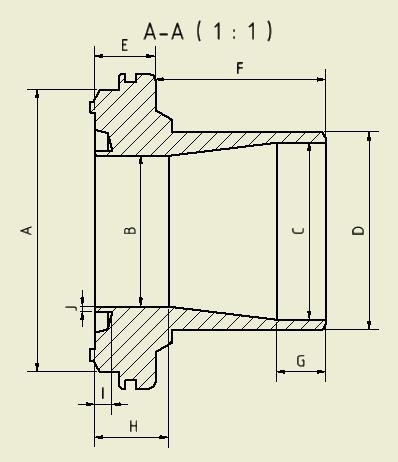
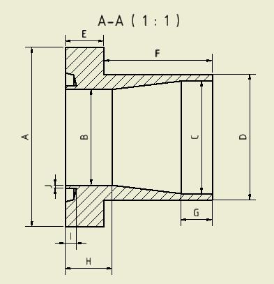
59 59 The specific force is added at the upper surface of the valve. Picture 43. Force at the TONISCO DN100 Gas Valve in Case Axial Forces The axial forces for the different cases and for different pressures can be calculated according to the following equation: g =O h g =O E 4 i The considered diameter depends on the size of the valve and the case. In the following picture the used diameter is shown for all cases.

60 60 Picture 44. Diameter for different Load Cases For case 1 and case 3 the diameter D1 was used to calculate the axial force for certain pressure. For case 2 the diameter D2 was used. Table 2. Diameter for different Load Cases Diameter [mm] DN50 DN80 DN100 Case 1,3 54 Case 2 49,2 Case 1,3 81 Case 2 74,3 Case 1,3 107,1 Case 2 104,2 The following table shows the axial forces which were applied for the different cases and valves in the FEM simulation according to this equation.
61 61 Table 3. Forces for different Load Cases Pressure Force [N] [bar] DN50 DN80 DN100 Case 1,3 Case 2 Case 1,3 Case 2 Case 1,3 Case
62 62 9 RESULTS OF THE LOAD CASES 9.1 Example (DN100, 25 bar) Case 1 Picture 45.Maximum Equivalent Stress in TONISCO DN100 Gas Valve in Case 1
 Picture 47.")
63 63 Picture 46. Maximum Equivalent Stress in TONISCO DN100 Gas Valve in Case 1 (lower Part is hidden) Picture 47.Maximum Equivalent Stress in the Welding of the TONISCO DN100 Gas Valve in Case 1

64 64 Picture 48. Maximum Equivalent Stress without the Welding of the TONISCO DN100 Gas Valve in Case 1 As can be seen the highest stresses occur in the welds at the sluice. It is also possible to show the deformation at the sluice which could affect the sealing effect. Since the maximum deformation of the defined area occurs in the upper part of the valve, the deformation of the lower part at the same area will be added to get the total deformation at the sluice. Picture 49. Deformation at the Sluice in Case 1

65 Case 2 Picture 50. Maximum Equivalent Stress in TONISCO DN100 Gas Valve in Case Picture 51. Maximum Equivalent Stress in TONISCO DN100 Gas Valve in Case 2 (lower Part is hidden)

66 66 Picture 52. Maximum Equivalent Stress in the Welding of the TONISCO DN100 Gas Valve in Case 2 Picture 53. Maximum Equivalent Stress without the Welding of the TONISCO DN100 Gas Valve in Case 2


67 67 As can be seen the highest stresses occur in the welds at the sluice. Picture 54. Deformation at the sluice in Case Case 3 Picture 55. Maximum Equivalent Stress in TONISCO DN100 Gas Valve in Case 3


68 68 Picture 56. Maximum Equivalent Stress in the Welding of the TONISCO DN100 Gas Valve in Case 3 Picture 57. Maximum Equivalent Stress without the Welding of the TONISCO DN100 Gas Valve in Case 3
69 69 As can be seen the highest stresses occur in the welds at the sluice. Picture 58. Deformation at the Sluice in Case 3 In this case the deformation at the sluice can be neglected because the shield should avoid all possible leakages. 9.2 Results 0-40 bar Since the stresses in the welding are the greatest in all cases, the maximums shown in the following graphs are the equivalent stresses in the welding.
70 DN Equivalent Stress [N/mm²] Pressure [bar] Case 1 Case 2 Case 3 Yield Strength (nonminal) Maxiumum allowed stress in welding Graph 9. Stresses in the welding of the TONISCO DN50 Gas Valve In the case simulations up to 40 bar do not show any yielding of the material With a pressure of 22 bar a maximum stress in the welding in case 2 of N/mm² is acquired DD E ' 01123(4,3(14*-. The DN50 valve can be used safely up to a pressure of 22 bar. Therefore this valve can be classified to a nominal pressure of PN16.
71 71 Equivalent Stress [N/mm²] Pressure [bar] Case 1 Case 2 Case 3 Yield Strength (nonminal) Maxiumum allowed stress Graph 10. Stresses without the Welding in the TONISCO DN50 Gas Valve As can be seen the material in the valve doesn t start to yield under a pressure of up to 40 bar. With a pressure of 30 bar a maximum stress in the welding in case 2 of N/mm² is acquired DD E ' 01123(4 The DN50 valve can be used safely up to a pressure of 30 bar. Therefore this valve can also be classified to a nominal pressure of PN25 if the stresses out of the welding are only considered.
72 72 Deformation at the Sluice [mm] 0,018 0,016 0,014 0,012 0,01 0,008 0,006 0,004 0,002 0 Case 1 Case 2 Case Pressure [bar] Graph 11. Deformation at the Sluice DN50 With a pressure of 22 bar (when the maximum allowable stress in the welding occurs) there is a deformation at the sluice of mm in case 1 and of mm in case 2. The deformation at the sluice in case 3 can be neglected because of the shield which keeps possible leakages. In case 1 the compression would decrease from 4.4 % to 4.3 % and in case 2 the compression would decrease from 15.4 % to 15.2 %. For PN16 there is a deformation at the sluice of mm in case 1 and of mm as well in case 2. In case 1 the compression would decrease from 4.4 % to 4.3 % and in case 2 the compression would decrease from 15.4 % to 15.3 %. As can be seen the deformation has not a huge effect on the compression of the seals.
73 DN Equivalent Stress [N/mm²] Pressure [bar] Case 1 Case 2 Case 3 Yield Strength (nominal) Maximum allowed stress in Welding Graph 12. Stresses without the Welding in the TONISCO DN80 Gas Valve As can be seen the material in the welding starts to yield over a yield strength of 355 N/mm². With a pressure of 18 bar a maximum stress in the welding in case 2 of 200 N/mm² is acquired. 200 DD E ' 01123(4,3(14*-. The DN80 valve can be used safely up to a pressure of 18 bar. Therefore this valve can be classified to a nominal pressure of PN16.
74 74 Equivalent Stress [N/mm²] Pressure [bar] Case 1 Case 2 Case 3 Yield Strength (nominal) Maximum allowed stress Graph 13. Stresses in the welding of the TONISCO DN80 Gas Valve As can be seen the material in the valve starts to yield under a yield strength of 355 N/mm². This issue happens probably because of the close connection to the welded part which starts to yield earlier. With a pressure of 25.4 bar a maximum stress in the welding in case 2 of N/mm² is acquired DD E ' 01123(4 The DN80 valve can be used safely up to a pressure of 25.4 bar. Therefore this valve can also be classified to a nominal pressure of PN16 if the stresses out of the welding are only considered.
75 75 0,035 Deformation at the Sluice[mm] 0,03 0,025 0,02 0,015 0,01 0,005 0 Case 1 Case 2 Case Pressure [bar] Graph 14. Deformation at the Sluice DN80 With a pressure of 18 bar (when the maximum allowable stress in the welding occurs) there is a deformation at the sluice of mm in case 1 and of mm in case 2. The deformation at the sluice in case 3 can be neglected because of the shield which keeps possible leakages. In case 1 the compression would decrease from 4.4 % to 4.2 % and in case 2 the compression would decrease from 17.5 % to 17.3 %. For PN16 there is a deformation at the sluice of mm in case 1 and of mm in case 2. In case 1 the compression would decrease from 4.4 % to 4.2 % and in case 2 the compression would decrease from 17.5 % to 17.3 %. As can be seen the deformation has not a huge effect on the compression of the seals.
76 DN100 Equivalent Stress [N/mm²] Pressure [bar] Case 1 Case 2 Case 3 Yield Strength (nominal) Maximum allowed stress in welding Graph 15. Stresses without the Welding in the TONISCO DN100 Gas Valve As can be seen the material in the welding starts to yield over a yield strength of 355 N/mm². The kink in the graph at 235 N/mm² can be seen as a numeric solve problem and because it happens over the allowed stress, it doesn t have to be considered as well. With a pressure of 11.2 bar a maximum stress in the welding in case 2 of N/mm² is acquired DD E ' 01123(4,3(14*-. The DN100 valve can be used safely up to a pressure of 11.2 bar. Therefore this valve can be classified to a nominal pressure of PN10.
77 77 Equivalent Stress [N/mm²] Pressure [bar] Case 1 Case 2 Case 3 Yield Strength (nominal) Maximum allowed stress Graph 16. Stresses in the welding of the TONISCO DN100 Gas Valve As can be seen the material in the valve starts to almost yield at a yield strength of 355 N/mm². With a pressure of 13.7 bar a maximum stress in the welding in case 2 of N/mm² is acquired DD E ' 01123(4 The DN100 valve can be used safely up to a pressure of 13.7 bar. Therefore this valve can be classified to a nominal pressure of PN10.
78 78 Deformation at the Sluice [mm] 0,1 0,09 0,08 0,07 0,06 0,05 0,04 0,03 0,02 0,01 0 Case 1 Case 2 Case Pressure [bar] Graph 17. Deformation at the Sluice DN100 With a pressure of 11.2 bar (when the maximum allowable stress in the welding occurs) there is a deformation at the sluice of mm in case 1 and of mm in case 2. The deformation at the sluice in case 3 can be neglected because of the shield which keeps possible leakages. In case 1 the compression would decrease from 4.4 % to 4.0 % and in case 2 the compression would decrease from 17.5 % to 17.1 %. For PN10 there is a deformation at the sluice of mm in case 1 and of mm in case 2. In case 1 the compression would decrease from 4.4 % to 4.0 % and in case 2 the compression would decrease from 17.5 % to 17.1 %. As can be seen the deformation has not a huge effect on the compression of the seals.
79 79 10 CONCLUSION Table 4. PN Classification In the welding Outside the welding PN Size Allowable stress [N/mm²] Simulated stress [N/mm²] at pressure [bar] Allowable stress [N/mm²] Simulated stress [N/mm²] at pressure [bar] Classification DN at at 30.0 PN10 DN at , at 25.4 PN16 DN at at 13.7 PN16 Because of the possibility to use TONISCO hot tapping gas valves in sizes DN50 and DN80 for a higher pressure than PN10, we have to re-categorize them according to Annex II of the Pressure Equipment Directive according to their level of hazard (DN50 for PN16, DN80 for PN16) =800 for DN =1280 for DN80 Because the solution of this categorization method for DN80 is higher than 1000, category II of Annex II must be applied and therefore the manufacturing has to be done by considering Module A1, D1 and E1 of Annex III of the Pressure Equipment Directive (Annex II section 1). For the DN50 gas valve only Module A has to be considered. (Pressure Equipment Directive 97/23/EC. 1997, 48.) Furthermore a datasheet for every certain valve is given in Appendix 3.
80 80 11 DISCUSSION AND CHALLENGES 11.1 Discussion Based on the FEA and the further calculations the TONISCO hot tapping gas valves can be seen as safe for given limitations which include the occurring conditions at the construction side (4-8 bar). The considered safety factor and the joint coefficient consider even reserves of the material and therefore the TONISCO hot tapping gas valves could be even used for higher stresses theoretically. Since the given standards are dictating the safety factor and the joint coefficient, it is not allowed to exceed the allowable stresses in the material. The local stress peaks have a very small influence to the gas valves which can be seen in the deformation at the sluice. The deformation depends linear on the pressure which shows that the stress peaks should be neglected technically. It would also be possible to consider the FKM-Guideline for the occurring stress peaks as an alternative calculation because the FKM-Guideline is not an accepted standard but is based on the latest technology. The highest stresses occur at the corners of the sluice. This area is welded and therefore the corners which were considered do not exist in reality. Probably there are smaller notches which could cause lower stresses. Since the highest stresses occur only for a short time in case 1 and case 2 which represent the installation of the TONISCO hot tapping gas valve, a surcharge for the wear of the valve in that area doesn t have to be considered. The highest stresses during the installation of the TONISCO hot tapping gas valves (case 2) are approximately 2.4 times higher than the stresses during the long term use of the valves (case 3). Therefore a safety factor of 3.6 for the long term use of the valves could be given in worst case for the highest allowable pressure.
81 81 Generally we could also consider the real material properties in the welding which are better than the properties of the main material and therefore we could give higher allowable pressures for the valves. Because this procedure is not allowed in any kind of standard because of the uncertainty of the joints, it is not recommended to use it. The deformation at the sluice can be neglected as well for usual conditions because they are as small that they do not affect the compression of the seals much Challenges Because the main purpose of my studies are in process engineering, I saw the solidity survey of TONISCO hot tapping gas valves as a great chance also to develop my experiences in mechanical engineering in the field of process engineering. Because the main market of the TONISCO hot tapping gas valves is in process engineering, it was a great opportunity to connect both subjects and therefore increase my ability to grasp larger issues in the future. Since the TONISCO hot tapping gas valves have difficult geometries some parts of the hand calculations and the modelling for the subsequently simulation with ANSYS Workbench was challenging. Also taking the right standards and regulations into account as well as the right choice of the material behavior and its properties was not easy at all to get reliable results for this survey. A great part of this thesis can be also seen as a practical part in which I familiarized myself with the FEM software ANSYS Workbench and with the CAD software Autodesk Inventor 2014 professional which I also see as a great chance to raise my experiences with such software. The implementation of this thesis was more challenging than I thought when I decided to write about this topic. Since I have used several other CAD software before, familiarizing myself with Autodesk Inventor 2014 professional was easier than I thought. But subsequently to learn how to use ANSYS Workbench was a big challenge for me, because I haven t done
82 82 anything with FEM before and therefore not with FEM software like ANSYS Workbench as well. The right understanding of the operation of the TONISCO hot tapping valves was challenging as well. The modelled parts have to be interpreted correctly and the right load cases have to be selected for the right solidity survey.
83 83 REFERENCES DIN EN [1] Flansche und ihre Verbindungen, Rohrleitungsteile, Definition und Auswahl von PN. Beuth Verlag GmbH Grote, K.-H., Feldhusen, J Dubbel Taschenbuch für den Maschinenbau. Germany: Springer Verlag Heinze, P Rechnerischer Festigkeitsnachweis mit der FKM-Richtline. Germany: Hochschule Wismar. Herz, Rolf Grundlagen der Rohrleitungs- und Apparatetechnik.Germany: Vulkan Verlag Neuberg Schweisstechnik Datasheet of joint fillers. Read Pressure Equipment Directive 97/23/EC Rust, Wilhelm Nichtlineare Finite Elemente Berechnung. Kontakt, Geometrie, Material. Germany: Vieweg und Teubner Smart Engineering Description of FEM. Read TONISCO. 2014a. Description of the company. Read TONISCO. 2014b. TONISCO welding information. Finland: TONISCO TONISCO. 2014c. TONISCO user manual. Description of the implementation of hot tapping. Read TONISCO. 2014d. TONISCO Internal Hot Tapping manual. TONISCO TONISCO. 2014e. Construction Information, Sealing Information. Finland: TONISCO Tüv e.v AD 2000 Regelwerk. Germany: Beuth Verlag GmbH Wittel H., Muhs D., Jannasch D.,Voßiek J. 2009a. Roloff/Matek Maschinenelemente. Germany: Springer Vieweg Wittel H., Muhs D., Jannasch D.,Voßiek J. 2009b. Roloff/Matek Maschinenelemente Tabellenbuch. Germany: Springer Vieweg Wossog, Günter Handbuch Rorleitungsbau Berechnung. Germany: Vulkan Verlag


84 84 APPENDICES Appendix 1. Modelling of the Welding Modelled welding DN50 Modelled welding DN80

85 Modelled welding DN100 85

 Simplifications of the")
86 86 Appendix 2. Simplifications Simplifications for calculations (DN50 as an example) Simplifications of the lower part Original: Simplified:
87 87 Simplifications of the upper part Original: Simplified:
STRESS ANALYSIS OF BICYCLE PADDLE AND OPTIMIZED BY FINITE ELEMENT METHOD. S. Abeygunasekara 1, T. M. M. Amarasekara 2
 - 96 - STRESS ANALYSIS OF BICYCLE PADDLE AND OPTIMIZED BY FINITE ELEMENT METHOD S. Abeygunasekara 1, T. M. M. Amarasekara 2 1 Faculty of Engineering & Technology, Colombo International Nautical Engineering
Design and Optimization of Weld Neck Flange for Pressure Vessel
 V th International Symposium on Fusion of Science & Technology, New Delhi, India, January 18-22, 2016 ID: 2016-ISFT-430 Design and Optimization of Weld Neck Flange for Pressure Vessel Vinod Kumar 1, Vivek
P-04 Stainless Steel Corrugated Hoses and Metal Bellows Expansion Joints
 Guideline No.P-04 (201510) P-04 Stainless Steel Corrugated Hoses and Metal Bellows Expansion Joints Issued date: 20 th October 2015 China Classification Society Foreword This Guideline is a part of CCS
STUDY OF UNDERWATER THRUSTER (UT) FRONT COVER OF MSI300 AUTONOMOUS UNDERWATER VEHICLE (AUV) USING FINITE ELEMENT ANALYSIS (FEA)
 FRONT COVER OF MSI300 AUTONOMOUS UNDERWATER VEHICLE (AUV) USING FINITE ELEMENT ANALYSIS (FEA)") STUDY OF UNDERWATER THRUSTER (UT) FRONT COVER OF MSI300 AUTONOMOUS UNDERWATER VEHICLE (AUV) USING FINITE ELEMENT ANALYSIS (FEA) M. Sabri 1, 2, T. Ahmad 1, M. F. M. A. Majid 1 and A. B. Muhamad Husaini
STUDY OF UNDERWATER THRUSTER (UT) FRONT COVER OF MSI300 AUTONOMOUS UNDERWATER VEHICLE (AUV) USING FINITE ELEMENT ANALYSIS (FEA) M. Sabri 1, 2, T. Ahmad 1, M. F. M. A. Majid 1 and A. B. Muhamad Husaini
2.1 Introduction to pressure vessels
 2.1 Introduction to pressure vessels Pressure vessels in the form of cylinders and tanks are used for storing variety of liquids and gasses at different temperatures and pressures. Some of the substances
FEA ANALYSIS OF PRESSURE VESSEL WITHDIFFERENT TYPE OF END CONNECTIONS
 FEA ANALYSIS OF PRESSURE VESSEL WITHDIFFERENT TYPE OF END CONNECTIONS Deval Nitin Bhinde 1 and Rajanarsimha S. 2 1 MTech CAD-CAM & Robotics, 2 Facculty, Department of Mechanical Engineering K.J. Somaiya
Stress evaluation of a bicycle crank arm connection using BEM
 Stress evaluation of a bicycle crank arm connection using BEM C. J. Hoff, R. E. Dippery & 3. Knapp Department of Mechanical Engineering Kettering University, USA Abstract An interesting problem encountered
Liquefied gas cargo tanks and process pressure vessels
 .1 -.3 Liquefied gas cargo tanks and process pressure vessels.1 General.1.1 The present texts give the general principles which are applied by Classification Societies for approval and survey of the relevant
Design and Analysis of Pressure Safety Release Valve by using Finite Element Analysis
 Design and Analysis of Pressure Safety Release Valve by using Finite Element Analysis Mr.V.D.Rathod* 1, Prof.G.A.Kadam* 2, Mr.V. G. Patil* 3 * 1 M.E. Design (Pursuing), SKN Sinhgad Institute of Technology&
OPENINGS AND REINFORCEMENTS 26
 ASME BPVC.VIII.1-2015 UG-35.2 UG-36 (4) It is recognized that it is impractical to write requirements to cover the multiplicity of devices used for quick access, or to prevent negligent operation or the
Hermetic Compressor Manifold Analysis With the Use of the Finite Element Method
 Purdue University Purdue e-pubs International Compressor Engineering Conference School of Mechanical Engineering 2008 Hermetic Compressor Manifold Analysis With the Use of the Finite Element Method Rinaldo
Published by: PIONEER RESEARCH & DEVELOPMENT GROUP (www.prdg.org) 113
 113") Design, Develop And Analysis Of Effortless Pressure Regulator Considering Pressure Vessel Aspect M. B. Chopade 1, S.N. Khan2 1, 2 Mechanical (Design), Pune University Rajarshi Shahu College of Engineering,
Design, Develop And Analysis Of Effortless Pressure Regulator Considering Pressure Vessel Aspect M. B. Chopade 1, S.N. Khan2 1, 2 Mechanical (Design), Pune University Rajarshi Shahu College of Engineering,
STRUCTURAL ANALYSIS OF THE VACUUM VESSEL FOR THE LHCb VERTEX LOCATOR (VELO)
") National Institute for Nuclear Physics and High Energy Physics Kruislaan 409 1098 SJ Amsterdam The Netherlands NIKHEF Reference no.: MT-VELO 04-1 EDMS no: 432626 OF THE VACUUM VESSEL FOR THE LHCb VERTEX
National Institute for Nuclear Physics and High Energy Physics Kruislaan 409 1098 SJ Amsterdam The Netherlands NIKHEF Reference no.: MT-VELO 04-1 EDMS no: 432626 OF THE VACUUM VESSEL FOR THE LHCb VERTEX
Tresca s or Mises Yield Condition in Pressure Vessel Design
 Tresca s or Mises Yield Condition in Pressure Vessel Design Franz Rauscher Institute for Pressure Vessels and Plant Technology Vienna University of Technology Austria Why using Tresca s yield condition
ISSN: Page 410
 Study of Structural Stability of Globe Valve in Petroleum and Sugar Industries Anil Rathod 1, Dr. S N Kurbet 2 1 PG Student Mechanical branch (machine Design) BEC Bagalkot, Karnataka India, 2 HOD of Mechanical
Pressure Equipment Directive (PED) 97/23/EC Page 033 of 124
 97/23/EC Page 033 of 124") Pressure Equipment Directive (PED) 97/23/EC Page 033 of 124 13.7 Pressure Equipment Directive (PED) 97/23/EC 1 The Pressure Equipment Directive (PED) 97/23/EC applies to the design, manufacturing and conformity
Pressure Equipment Directive (PED) 97/23/EC Page 033 of 124 13.7 Pressure Equipment Directive (PED) 97/23/EC 1 The Pressure Equipment Directive (PED) 97/23/EC applies to the design, manufacturing and conformity
6995(Print), ISSN (Online) Volume 4, Issue 1, January- April (2013), IAEME TECHNOLOGY (IJDMT)
, ISSN (Online) Volume 4, Issue 1, January- April (2013), IAEME TECHNOLOGY (IJDMT)") International INTERNATIONAL Journal of Design JOURNAL and Manufacturing OF DESIGN Technology AND MANUFACTURING (IJDMT), ISSN 0976 TECHNOLOGY (IJDMT) ISSN 0976 6995 (Print) ISSN 0976 7002 (Online) Volume
International INTERNATIONAL Journal of Design JOURNAL and Manufacturing OF DESIGN Technology AND MANUFACTURING (IJDMT), ISSN 0976 TECHNOLOGY (IJDMT) ISSN 0976 6995 (Print) ISSN 0976 7002 (Online) Volume
Engineering Practice on Ice Propeller Strength Assessment Based on IACS Polar Ice Rule URI3
 10th International Symposium on Practical Design of Ships and Other Floating Structures Houston, Texas, United States of America 2007 American Bureau of Shipping Engineering Practice on Ice Propeller Strength
The Powerful Sealing Calculation
 KLINGER expert 6.0 The Powerful Sealing Calculation The KLINGER expert 6.0 gasket design program is a versatile software to assist users in the selection of non-metallic gasket materials. www.klinger.co.at
Fatigue Resistant Sockets for Dynamic Loads PFEIFER Cable Structures. Cable structures technology Info Nr PFEIFER SEIL- UND HEBETECHNIK GMBH
 Fatigue Resistant Sockets for Dynamic Loads Cable Structures Cable structures technology Info Nr. 3 4-2012 SEIL- UND HEBETECHNIK GMBH DR.-KARL-LENZ-STRASSE 66 D-87700 MEMMINGEN TELEPHONE +49 (0) 83 31-937-393
FEA case Study: Rubber expansion joint for piping systems
 FEA case Study: Rubber expansion joint for piping systems Introduction The FEA Toolbox of Taniq makes it possible to simulate the behavior of a pipe expansion joint accurately under several load cases.
Elastic-Plastic Finite Element Analysis for Zhongwei--guiyang Natural Gas Pipeline Endangered by Collapse
 Abstract Elastic-Plastic Finite Element Analysis for Zhongwei--guiyang Natural Gas Pipeline Endangered by Collapse Gengxin Wu,Peng Zhang,Zhixiang Li,Zunhai Ke,Guizhi Li,Anmin Jiang 2 School of Civil Engineering
DESIGN AND ANALYSIS OF PRESSURE VESSEL
 DESIGN AND ANALYSIS OF PRESSURE VESSEL Vrushali Dilip Solapurkar 1 Assistant Professor, Mechanical Engineering Department, Vadodara Institute of Engineering, Gujarat, India ABSTRACT This technical paper
STRESS ANALYSIS OF RATCHET PAWL DESIGN IN HOIST USING FINITE ELEMENT ANALYSIS
 STRESS ANALYSIS OF RATCHET PAWL DESIGN IN HOIST USING FINITE ELEMENT ANALYSIS 1* Hariyali M.Patil, 2 P.A.Chandak 1 (Department of MechanicalEngineering, DMIETR/ Nagpur, India) 2( Department of MechanicalEngineering,
Experimental Method to Analyse Limit Load in Pressure Vessel
 International OPEN ACCESS Journal Of Modern Engineering Research (IJMER) Dilip M. Patel 1, Dr. Bimlesh Kumar 2 1 Mechanical Department D.N.Patel COE, Shahada 2 Mechanical Department COE, Faizpur Abstract:
DESIGN AND DEVELOPMENT OF A RIG FOR THE PRESSURE TESTING OF WEAK VESSELS AND SUBSEQUENT WORK RELATING TO THE STRENGTH OF FLAT PLATES
 DESIGN AND DEVELOPMENT OF A RIG FOR THE PRESSURE TESTING OF WEAK VESSELS AND SUBSEQUENT WORK RELATING TO THE STRENGTH OF FLAT PLATES D.F. Pilkington Ph.D. B.Sc(Eng)*, G Piatt B.Sc.*, G. Norton B.Sc.**
Design and Analysis of an Unfired Pressure Vessel for Conducting Pressure Test
 IJIRST International Journal for Innovative Research in Science & Technology Volume 4 Issue 3 August 2017 ISSN (online): 2349-6010 Design and Analysis of an Unfired Pressure Vessel for Conducting Pressure
Pressure Equipment Directive PED 2014/68/EU Commission's Working Group "Pressure"
 H. INTERPRETATION OF OTHER ESSENTIAL SAFETY REQUIREMENTS Guideline H-02 Guideline related to: Annex I Section 3.2.2 and 7.4 Final assessment (Annex I Section 3.2.2) of pressure equipment must include a
Plastic non-symmetric bifurcation buckling of circular cylinders under uniform external hydrostatic pressure
 icccbe 2010 Nottingham University Press Proceedings of the International Conference on Computing in Civil and Building Engineering W Tizani (Editor) Plastic non-symmetric bifurcation buckling of circular
Návrh vratného kanálu u dvoustupňového kompresoru Return channel design of the two stage compressor
 Návrh vratného kanálu u dvoustupňového kompresoru Return channel design of the two stage compressor J. Hrabovský, J. Vacula, M. Komárek L. K. Engineering, s.r.o C. Drápela, M. Vacek, J. Klíma PBS Turbo
The Industrial Accident Resulted from the Failure of Bolt
 The Industrial Accident Resulted from the Failure of Bolt Hyun Wook YEO 1, Jae Min LEE 2 and Sang Won CHOI 1, * 1 Occupational Safety and Health Research Institute, Korea Occupational Safety and Health
Structural Design and Analysis of the New Mobile Refuge Chamber
 Key Engineering Materials Online: 2013-09-10 ISSN: 1662-9795, Vol. 584, pp 175-178 doi:10.4028/www.scientific.net/kem.584.175 2014 Trans Tech Publications, Switzerland Structural Design and Analysis of
Modeling and FEA Analysis of Ball Valve
 Modeling and FEA Analysis of Ball Valve Parth Mandanaka Krishna M Tadvi 2 Prof. Hitesh Raiyani 3 Post-Graduate Student, 2 Post-Graduate Student, 3 Assistant Professor, Mechanical Engineering Department,
Copyright by Turbomachinery Laboratory, Texas A&M University
 Proceedings of the 2 nd Middle East Turbomachinery Symposium 17 20 March, 2013, Doha, Qatar Effectiveness of Windage Features on High Speed Couplings Steven Pennington Global Engineering Manager John Crane
Mounting and Operating Instructions EB 3007 EN. Self-operated Pressure Regulators. Differential Pressure Regulators (opening) Type Type 42-25
 Type Type 42-25") Self-operated Pressure Regulators Differential Pressure Regulators (opening) Type 42-20 Type 42-25 Type 42-20 Differential Pressure Regulator Type 42-25 Differential Pressure Regulator Mounting and Operating
Self-operated Pressure Regulators Differential Pressure Regulators (opening) Type 42-20 Type 42-25 Type 42-20 Differential Pressure Regulator Type 42-25 Differential Pressure Regulator Mounting and Operating
Study to Establish Relations for the Relative Strength of API 650 Cone Roof Roof-to-Shell and Shell-to- Bottom Joints
 Thunderhead Engineering Consultants I N C O R P O R A T E D 1006 Poyntz Ave. Manhattan, KS 66502-5459 785-770-8511 www. thunderheadeng.com Study to Establish Relations for the Relative Strength of API
Design and Analysis of Rotary Lawn Mower
 Design and Analysis of Rotary Lawn Mower Vivek P Revi Vishnu N V Akhil K A Rohith P Kevin Rozario Abstract- KAMCO Industries, Athani, India is a reputed industry undertaken by Kerala state government producing
Spilt body Flange ball valve. TC-205MFF-PN1640 User Manual English Version. Document No: TC-205MFF-PN1640.Ur-manual. Date: 2007/04/2617. Version: 1.
 Spilt body Flange ball valve TC-205MFF-PN1640 Series PED Category I,II TC-205MFF-PN1640 User Manual English Version Use for company in Europe who will place the product on the market, please amend which
Sense Element Pump Ripple Fatigue
 white paper Sense Element Pump Ripple Fatigue Providing and analyzing solutions to protect sensitive components in aircraft hydraulic systems from prolonged exposure to pump ripple. 2 CONTENTS Sense Element
A New Piston Gauge to Improve the Definition of High Gas Pressure and to Facilitate the Gas to Oil Transition in a Pressure Calibration Chain
 A New iston Gauge to Improve the Definition of High Gas ressure and to Facilitate the Gas to Oil Transition in a ressure Calibration Chain ierre Delajoud, Martin Girard DH Instruments, Inc. 4765 East Beautiful
General page Straight unions page Angle unions page Tee and L-unions page Gauge connection unions page 42
 C 2610-00 Table of contents General page 3-13 DILO unions for pressure ranges from 100 320 bar Straight unions page 14-25 Weld-on tube unions page 14-16 Screw-in tube unions page 17-25 with metric / Whitworth-
Analysis of dilatometer test in calibration chamber
 Analysis of dilatometer test in calibration chamber Lech Bałachowski Gdańsk University of Technology, Poland Keywords: calibration chamber, DMT, quartz sand, FEM ABSTRACT: Because DMT in calibration test
DESIGN OF AN UNDERWATER TOWFISH USING DESIGN BY RULE AND DESIGN BY ANALYSIS
 Proceedings of the ASME 204 Pressure Vessels & Piping Conference PVP204 July 20-24, 204, Anaheim, California, USA PVP204-2822 DESIGN OF AN UNDERWATER TOWFISH USING DESIGN B RULE AND DESIGN B ANALSIS Martin
Hilti, Inc South 122 nd East Avenue Tulsa, OK
 Attached are page(s) from the 2014 Hilti North American Product Tech Guide. For complete details on this product, including data development, product specifications, general suitability, installation,
Design Project 2 Sizing of a Bicycle Chain Ring Bolt Set ENGR 0135 Sangyeop Lee November 16, 2016 Jordan Gittleman Noah Sargent Seth Strayer Desmond
 1 Design Project 2 Sizing of a Bicycle Chain Ring Bolt Set ENGR 0135 Sangyeop Lee November 16, 2016 Jordan Gittleman Noah Sargent Seth Strayer Desmond Zheng 2 Abstract This report will analyze our calculations,
CHAPTER IV FINITE ELEMENT ANALYSIS OF THE KNEE JOINT WITHOUT A MEDICAL IMPLANT
 39 CHAPTER IV FINITE ELEMENT ANALYSIS OF THE KNEE JOINT WITHOUT A MEDICAL IMPLANT 4.1 Modeling in Biomechanics The human body, apart of all its other functions is a mechanical mechanism and a structure,
Finite Element Analysis of an Aluminium Bike Frame
 Finite Element Analysis of an Aluminium Bike Frame Word Count: 1484 1 1. Introduction Each new bike model must pass a series of structural tests before being released for public retail. The purpose of
Optimize Nozzle Location For Minimization Of Strees In Pressure Vessel
 IJIRST International Journal for Innovative Research in Science & Technology Vol. 1, Issue 1, June 2014 ISSN(online): 2349-6010 Optimize Nozzle Location For Minimization Of Strees In Pressure Vessel Shyam
Analysis of Shear Lag in Steel Angle Connectors
 University of New Hampshire University of New Hampshire Scholars' Repository Honors Theses and Capstones Student Scholarship Spring 2013 Analysis of Shear Lag in Steel Angle Connectors Benjamin Sawyer
STIFFNESS INVESTIGATION OF PNEUMATIC CYLINDERS. A. Czmerk, A. Bojtos ABSTRACT
 59 th ILMENAU SCIENTIFIC COLLOQUIUM Technische Universität Ilmenau, 11 15 September 2017 URN: urn:nbn:de:gbv:ilm1-2017iwk-148:6 STIFFNESS INVESTIGATION OF PNEUMATIC CYLINDERS A. Czmerk, A. Bojtos Budapest
Residual Stresses in Railway Axles
 Residual Stresses in Railway Axles ŘEHA BOHUSLAV 1,a,*, VÁCLAVÍK JAROSLAV 2,b NÁVRAT TOMÁŠ 3,c and DAVID HALABUK 3,d 1 GHH-BONATRANS GROUP a.s., Revoluční 1234, 735 94 Bohumín, Czech Republic 2 Výzkumný
MAE 322 Machine Design Lecture 5 Fatigue - 2. Dr. Hodge Jenkins Mercer University
 MAE 322 Machine Design Lecture 5 Fatigue - 2 Dr. Hodge Jenkins Mercer University Returning to Stress-Life Fatigue Modeling Fatigue Stress-Life: S f -N Diagram for steels Stress levels below S e (Endurance
Research Article Volume 6 Issue No. 6
 DOI 10.4010/2016.1835 ISSN 2321 3361 2016 IJESC ` Research Article Volume 6 Issue No. 6 Design, Analysis and Development of Pressure Vessel Lug Support Vishal S. Telgote 1, Prof.G.E.Kondhalkar, Guide,
The Relationship between the Depth Embedded Pipe Pile and the Force of Clamping Jaw
 IOP Conference Series: Materials Science and Engineering PAPER OPEN ACCESS The Relationship between the Depth Embedded Pipe Pile and the Force of Clamping Jaw To cite this article: Yu Wentai et al 018
PVP Copyright 2009 by ASME
 Proceedings of PVP 009 009 ASME Pressure Vessel and Piping Division Conference July 6-30, 009, Prague, Czech Republic PVP009-7746 UPDATE OF THE TABULATED «M AND Y» VALUES IN THE NEW REVISIONS OF FRENCH
Mechanical Anchoring Systems HDA Undercut Anchor Product description. HDA-P Undercut Anchor Pre-Set Type
 Mechanical Anchoring Systems 3.3 3.3.1 HDA Undercut Anchor 3.3.1.1 Product description The Hilti HDA undercut anchor is a heavy-duty mechanical anchor with carbide-tipped undercut segments used to perform
Bottom End-Closure Design Optimization of DOT-39 Non-Refillable Refrigerant Cylinders
 Y. Kisioglu a) Department of Mechanical Education, Kocaeli University, Izmit, Kocaeli, 41100, Turkey J. R. Brevick Industrial and Systems Engineering, The Ohio State University, Columbus, Ohio G. L. Kinzel
Analysis of Jump-Out Loads about Connectors of Buttress and Round Threads of Casing
 nalysis of Jump-Out Loads about onnectors of uttress and Round Threads of asing Lian Zhanghua, Liu Yonggang, Tang o Southwest Petroleum Institute, P.R. Of hina Han Jianzeng, Zhang Yi Shanghai aoshan Iron
3-PIECE BALL VALVE, 3600 PSI/ PN 248, WITH ISO DIRECT MOUNTING PAD 306M SERIES/ PED Category II
 3-PIECE BALL VALVE, 3600 PSI/ PN 248, WITH ISO DIRECT MOUNTING PAD 306M SERIES/ PED Category II 306M User Manual English Version Use for company in Europe who will place the product on the market, please
Design of Pressure vessel for the Hydrocarbon release from the Vent Header Lines
 Design of Pressure vessel for the Hydrocarbon release from the Vent Header Lines Bhargav Mangesh Joshi 1 1Student, Department of mechanical engineering, Modern college of engineering, Pune-5 ---------------------------------------------------------------------***---------------------------------------------------------------------
Analysis and Optimization of Stress on Horizontal Pressure Vessel by Varying Opening Angle and Location
 Analysis and Optimization of Stress on Horizontal Pressure Vessel by Varying Opening Angle and Location Bhupendra V. Barjod #1, Prof. Ronak Shah *2 # PG student Mechanical Department, Kalol Institute of
Design and Safety Document for the Vacuum Windows of the NPDGamma Liquid Hydrogen Target at SNS
 Design and Safety Document for the Vacuum Windows of the NPDGamma Liquid Hydrogen Target at SNS Prepared: Checked: Approved: H. Nann W. Fox M. Snow The NPDGamma experiment is going to run at BL13 at SNS
Analysis of Pressure Safety Relief Valve using Finite Element Analysis
 Analysis of Pressure Safety Relief Valve using Finite Element Analysis 1 Mr. M. V. Awati, 2 Prof. S. G. Jadhav, 3 Vinay G. Patil 1 P.G.Student, 2 Proffessor, 3 Consultant 1 Mechanical Department, Veermata
Engineering Data Sheet
 Page 1 of 6 CE MARKING AND THE PRESSURE EQUIPMENT DIRECTIVE 97/23/EC Valves must be installed into a well designed system and it is recommended that the system be inspected in accordance with the appropriate
TIGHTNESS. Glass sealing Thanks to our glass-sealing technology, ODU products can meet the most demanding tightness requirements.
 TIGHTNESS Glass sealing Thanks to our glass-sealing technology, ODU products can meet the most demanding tightness requirements. ODU has the necessary expertise for developing and manufacturing connectors
International Journal of Scientific & Engineering Research, Volume 6, Issue 9, September-2015 ISSN
 827 MEMS PRESSURE RELIEF VALVE: DESIGN, MODEL AND STATIC ANALYSIS Anand M. Shelke, Amit Cherian, Sandesh A. Ghate Guided by Prof. DRS Raghuraman M.Tech (Mechatronics) School of Mechanical and Building
Operating instruction for the quick-change tap holders type:
 type: HF 20 HF 30 Date of edition: 15.07.2008 Stage of alteration: 4 Please keep this for future use! Contents: 1 Application range, safety instructions and technical data... 3 1.1 Application range,
STRESS ANALYSIS OF BELL CRANK LEVER
 STRESS ANALYSIS OF BELL CRANK LEVER Mr. M. M. Dange 1, Prof. S. R. Zaveri 2 1 Department of Mechanical Engineering, R.C.E.R.T., R.T.M.N.U, Chandrapur, (India) 2 Department of Mechanical Engineering, R.C.E.R.T.,
Queue analysis for the toll station of the Öresund fixed link. Pontus Matstoms *
 Queue analysis for the toll station of the Öresund fixed link Pontus Matstoms * Abstract A new simulation model for queue and capacity analysis of a toll station is presented. The model and its software
Telefon (+45) Telefax (+45)
 Telefax (+45)") Uni-Valve A /S VENTILER & INSTRUMENTER Telefon (+45) 43 43 82 00 Telefax (+45) 43 43 74 75 mail@uni-valve.com www.uni-valve.com UNI-S83 / S84 3/4-way ball valve Installation and Operating manual 3/4-WAY
Uni-Valve A /S VENTILER & INSTRUMENTER Telefon (+45) 43 43 82 00 Telefax (+45) 43 43 74 75 mail@uni-valve.com www.uni-valve.com UNI-S83 / S84 3/4-way ball valve Installation and Operating manual 3/4-WAY
BSI BSI 5200 THE NEW CAST 60 FITTINGS AN EASY ASSEMBLY A KNOWN PRODUCT, SAFE AND RELIABLE AVAILABLE IN CARBON AND STAINLESS STEEL
 THE NEW CAST 60 FITTINGS AN EASY ASSEMBLY A KNOWN PRODUCT, SAFE AND RELIABLE AVAILABLE IN CARBON AND STAINLESS STEEL 55 THEORY OF OPERATION The CAST S.p.A. fitting according to the norms, is a mechanical
The Study of Half-tooth Master Gear Structure Optimization Yazhou Xie a, Zhiliang Qian b
 X 3rd International Conference on Mechatronics, Robotics and Automation (ICMRA 2015) The Study of Half-tooth Master Gear Structure Optimization Yazhou Xie a, Zhiliang Qian b School of Mechanical and Electric
WELCOME to CAUx Local India 2018
 WELCOME to CAUx Local India 2018 Flange Design In Detail Prepared by Sachin Pol and Fauzan Badiwale Some Typical Flange Images 3 Some Typical Gasket Images 4 Flange Design As Per ASME Sec.VIII Div.1 Mandatory
ASME Boiler & Pressure Vessel Code Analysis of the 1497 MHz High-Current Cryomodule Helium Vessel
 1.0 Introduction ASME Boiler & Pressure Vessel Code Analysis of the 1497 MHz High-Current Cryomodule Helium Vessel Katherine Wilson 28 May 2007 To minimize the hazards associated with vacuum and pressure
Materials : Stainless steel ASTM A351 CF8M
 Certificat 3.1 Size: Ends : Min Temperature : Max Temperature : DN 15 to DN 200 PN16 Flanges R.F. - 20 C + 200 C Max Pressure : 16 Bars Specifiations : Removable stainless steel filter Bolted bonnet with
Ball Valves for Heating and District Heating. Date 1
 Ball Valves for Heating and District Heating Date 1 Underground Ball Valves DN 20 DN 600, PN25 Underground valves are installed in pre insulated pipe systems, transporting hot water from production to
Continental Industries TRANSITION FITTINGS or FAX Visit
 Continental Industries TRANSITION FITTINGS 1-800-558-1373 or FAX 1-800-788-1668 Visit www.conind.com ABOUT US Our Company Continental Industries, headquartered in Tulsa, Oklahoma, was formed in 1958 and
OPTIMIZATION OF SINGLE STAGE AXIAL FLOW COMPRESSOR FOR DIFFERENT ROTATIONAL SPEED USING CFD
 http:// OPTIMIZATION OF SINGLE STAGE AXIAL FLOW COMPRESSOR FOR DIFFERENT ROTATIONAL SPEED USING CFD Anand Kumar S malipatil 1, Anantharaja M.H 2 1,2 Department of Thermal Power Engineering, VTU-RO Gulbarga,
Vessels subject to External Pressure
 Basic principles of compressive force Vessels subject to External Pressure Before After The result of just air pressure! Presented by: Ray Delaforce Basic principles of compressive force Consider For a
Fatigue Life Evaluation of Cross Tubes of Helicopter Skid Landing Gear System
 IJSRD - International Journal for Scientific Research & Development Vol. 3, Issue 04, 2015 ISSN (online): 2321-0613 Fatigue Life Evaluation of Cross Tubes of Helicopter Skid Landing Gear System Madhu S
MAKING MODERN LIVING POSSIBLE. Pilot operated internal safety valves type POV REFRIGERATION AND AIR CONDITIONING DIVISION.
 MAKING MODERN LIVING POSSIBLE Pilot operated internal safety valves type POV REFRIGERATION AND AIR CONDITIONING DIVISION Technical leaflet Contents Page Introduction...3 Features...3 Design...4 Technical
PVP2006-ICPVT
 Proceedings of PVP2006 / ICPVT-11: 11 th International Conference on Pressure Vessel Technology July 23-37, 2006, Vancouver, Canada PVP2006-ICPVT11-93020 DESIGN OF A LARGE RECTANGULAR FLANGE Bharat Batra,
Gas Pressure Regulator HON 200
 Product information serving the gas industry worldwide Applications, characteristics, technical data Application Gas supply to municipal, industrial and individual consumers Regulator for low-load rails
Sizes Weight Gripping force Stroke per finger Workpiece weight Pieces : kg N mm kg
 MPG-plus Sizes Weight Gripping force Stroke per finger Workpiece weight Pieces : 7 0.06.. 0.63 kg 25.. 350 N 1.5.. 10 mm 0.19.. 1.25 kg Application example Pneumatically driven, dual-axis pick-andplace
MPG-plus. Application example. Pneumatic 2-Finger Parallel Gripper Gripper for small components. Gripping force 38 N 175 N. Sizes
 MPG-plus Sizes 25 40 Weight 0.06 kg 0.24 kg Gripping force 38 N 175 N Stroke per finger 3 mm 6 mm Workpiece weight 0.19 kg 0.7 kg Application example Pneumatically driven, dual-axis pick-and-place machine
CAST IRON SAFETY VALVE TYPE 6301
 CHARACTERISTICS The 6301 safety valve is dedicated to protect the equipment from potential overpressure. This is an automatic device that closes when the pressure conditions are back to normal. It is a
Design and Finite Element Analysis of Fabricated Panama chock with 225T capacity
 LOWER HULL TOP DEC K EL. 3 1 ' - 2 " AB L [ 9 5 0 0 ] ( E) AIR DUC T ( INB D) ( E) B HD 1 4 m m `AH' ( E) PL. 1 2 m m `AH' ( E) L 1 5 0 x9 0 x1 2 m m `AH' - DO- - DO- SMIT BRACKET PANAMA CHOCK International
Unit 24: Applications of Pneumatics and Hydraulics
 Unit 24: Applications of Pneumatics and Hydraulics Unit code: J/601/1496 QCF level: 4 Credit value: 15 OUTCOME 2 TUTORIAL 9 ACCUMULATORS The material needed for outcome 2 is very extensive so there are
INTRODUCTION TABLE OF CONTENTS
 2 INTRODUCTION Thank you for choosing Servometer to design and manufacture your unique, new electrodeposited bellows for your particular application. The definitions, formulas and design parameters inside
Characterizing Flow Losses Occurring in Air Vents and Ejector Pins in High Pressure Die Castings
 This paper is subject to revision. Statements and opinions advanced in this paper or during presentation are the author s and are his/her responsibility, not the Association s. The paper has been edited
ZIN Technologies PHi Engineering Support. PHi-RPT CFD Analysis of Large Bubble Mixing. June 26, 2006
 ZIN Technologies PHi Engineering Support PHi-RPT-0002 CFD Analysis of Large Bubble Mixing Proprietary ZIN Technologies, Inc. For nearly five decades, ZIN Technologies has provided integrated products and
DN 1/2" to 2" Female BSP + 0 C C Max Pressure : 16 Bars Specifications : Stainless steel removable filter Female / Female With draining valve
 Size : Ends : Min Temperature : Max Temperature : DN 1/2" to 2" Female BSP + 0 C + 120 C Max Pressure : 16 Bars Specifications : Stainless steel removable filter Female / Female With draining valve Materials
The Discussion of this exercise covers the following points:
 Exercise 3-2 Orifice Plates EXERCISE OBJECTIVE In this exercise, you will study how differential pressure flowmeters operate. You will describe the relationship between the flow rate and the pressure drop
International Journal of Modern Trends in Engineering and Research e-issn No.: , Date: 2-4 July, 2015
 International Journal of Modern Trends in Engineering and Research www.ijmter.com e-issn No.:2349-9745, Date: 2-4 July, 2015 Fillet Radius Optimization of Bell Crank Lever Swapneel R. Zende 1, Mohammed
EEF. Fatigue Testing Unit PROCESS DIAGRAM AND UNIT ELEMENTS ALLOCATION. Engineering and Technical Teaching Equipment
 Engineering and Technical Teaching Equipment Fatigue Testing Unit EEF PROCESS DIAGRAM AND UNIT ELEMENTS ALLOCATION ISO 9001: Quality Management (for Design, Manufacturing, Commercialization and After-sales
Safety relief valves Type BSV-8
 Data sheet Safety relief valves Type BSV-8 BSV is a standard, back pressure independent safety relief valve, especially designed for protection of small components against excessive pressure and as a pilot
Wafer Check Valve. Contents. User s Manual. (1) Be sure to read the following description of our product warranty 1
 Be sure to read the following description of our product warranty 1") Serial No. H-V066-E-3 Wafer Check Valve User s Manual Contents (1) Be sure to read the following description of our product warranty 1 (2) General operating instructions 2 (3) General instructions for
Serial No. H-V066-E-3 Wafer Check Valve User s Manual Contents (1) Be sure to read the following description of our product warranty 1 (2) General operating instructions 2 (3) General instructions for
σ = force / surface area force act upon In the image above, the surface area would be (Face height) * (Face width).
 * (Face width).") Aortic Root Inflation Introduction You have already learned about the mechanical properties of materials in the cantilever beam experiment. In that experiment you used bending forces to determine the Young
Aortic Root Inflation Introduction You have already learned about the mechanical properties of materials in the cantilever beam experiment. In that experiment you used bending forces to determine the Young
Safety Manual VEGAVIB series 60
 Safety Manual VEGAVIB series 60 NAMUR Document ID: 32005 Contents Contents 1 Functional safety... 3 1.1 General information... 3 1.2 Planning... 4 1.3 Adjustment instructions... 6 1.4 Setup... 6 1.5 Reaction
CONVECTION SECTION FAILURE ANALYSIS AND FITNESS-FOR-SERVICE ASSESSMENT
 ASSET INTEGRITY INTELLIGENCE CONVECTION SECTION FAILURE ANALYSIS AND FITNESS-FOR-SERVICE ASSESSMENT JAMES R. WIDRIG, Manager Advanced Engineering at Quest Integrity Group VOLUME 23, ISSUE 6 NOVEMBER DECEMBER