Engineering Letter. Pump Protection
|
|
|
- Gertrude Nash
- 5 years ago
- Views:
Transcription
1 Engineering Letter Pump Protection
2
3 Content 1. Introduction What systems are available to ensure the minimum flow through the pump at all times? Continuous Bypass System Controlled Bypass System Automatic Recirculation Valves The Automatic Recirculation Valve Application - Details General ARV Information ARV Installation Recommendations Schroedhal ARV Types The ARV Functioning / Flow Curve ARV Operation on Pump Curve ARV Application with Speed Operated Pumps Engineering Guideline for ARVs ARV Data Sheet for Communication and RFQ Signal Exchange of the Minimum Flow Control System Schematic Arrangement for Control Valve Solution with Venturi Nozzle at Pump Discharge and Signal Controlled Pump Speed...14 Notes...15


4
5 Introduction Owing to necessary cost reductions, a higher system efficiency and risk management, a reliable system to ensure a minimum flow through the pump is a prime requirement, especially for high pressure applications. Besides protecting the pump against overheating, a well-engineered, modulating, controlled bypass system improves the stable operation of the complete system. The system itself is usually a closed loop application and therefore consists of a suction and recirculation line from and back to the tank. Much consideration is given to the materials to be used for the valves in order to minimise corrosion and erosion under high velocity conditions or special medium applications. Important advice In general and especially for high pressure applications, all equipment including the valves should fulfil the following requirements: Reliable operation Production stops are very costly and it pays to accept higher initial investment rather than go for the most inexpensive solution (inexpensive can be very expensive!). Ease of maintenance, good serviceability Although platform personnel includes highly trained technicians, the equipment should be maintenance-free or require little maintenance by the platform engineers. Time is scarce, and time costs money, especially on platforms. Long life of the valve and its trim parts In order to prevent production loss or unnecessary doubling of control systems. Again, a cost factor! 1
6 1.1 What systems are available to ensure the minimum flow through the pump at all times? Continuous Bypass System These systems continuously bypass the flow that is required as a minimum to prevent overheating of the high pressure injection pumps. Minimum flow is usually approx. 30 % of the normal flow. The pressure at which the water is injected causes a tremendous loss of energy. Therefore, the pump to be selected should be larger in size as well as the installed capacity of the driver (130 %). Tank Also, a pressure reduction system has to be provided with orifice plates which are subject to cavitation and wear. An additional check valve is needed! Pay attention to saving costs for high pressure applications! In a typical high pressure injection system with a normal flow of 625 m 3 /h (per pump), the bypass flow required is a minimum of 125 m 3 /h (usually m 3 /h). At a pump head of 2150 m the extra power consumption of the larger pumps would be 950 kw per hour. In continuous operation (say 300 days per year) and energy costs of 3 cents per kw/h, the extra energy costs would be roughly $200,000. This system is therefore very costly and it is bad engineering practice. 2
7 1.1.2 Controlled Bypass System This system consists of: A control valve in the bypass. This control valve should be designed for high pressure reduction (e.g. from 200 bar down to 5 bar or lower). Usually, a four-stage trim (or more, depending on the make) is required and it should be equipped with an actuator to provide modulating control. It should also be available in the materials as required. Tank A flow sensor in the suctionline, which senses the low flow conditions to the pump. Also available in a material as specified. A control loop which transmits the signal from the flow sensor to the control valve actuator. This requires an air or electrical supply system and requires regular maintenance and calibration. An additional check valve is needed! The check valve is located on the pump outlet to prevent back flow if the pump is not running. Again, the availability of the correct material for this check valve should be considered. This system has been applied (and still is) in many high pressure systems. It offers a good control of the bypass flow but has some drawbacks when compared to the system of an Automatic Recirculation Valve. 3
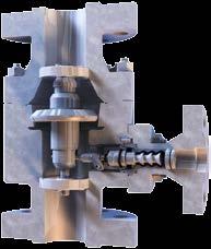
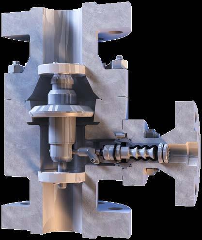
8 1.1.3 Automatic Recirculation Valves The Automatic Recirculation Valve, manufactured and marketed by SCHROEDAHL for almost 50 years, combines the 4 functions as outlined earlier in one simple unit (see below). Tank The SCHROEDAHL ARV is distinguished by: 1. Flow sensing and modulating function 2. Check valve 3. Automatic bypass end connection 4. Pressure reduction of the bypass flow without cavitation This results in the following advantages compared to conventional systems: One self-operated unit only, which can be mounted directly on the pump outlet. No external energy required. Reliable, direct operation with little hysteresis. No special maintenance required; the unit is self-lubricating (pump fluid). Conclusion The SCHROEDAHL valves are the most reliable valves providing minimum flow through a pump. They have many advantages over other systems and are low in initial cost (approx % of a conventional system).the valves are based on the latest technology and SCHROEDAHL has nearly 50 years of experience since the valve was invented by Mr. Odendahl of SCHROEDAHL. 4
9 The Automatic Recirculation Valve Application Details 2.1 General ARV Information Q P 2 Suction tank Q A P A P N Q min Q Manual start-up* P 1 Bypass Pump P V *Manual start-up on request /optional Explanation The Automatic Recirculation Valve (ARV) protects centrifugal pumps against overheating and cavitation problems by automatically maintaining a minimum flow when the system flow is in low load condition. The application itself is usually a closed loop application and consists of a suction and recirculation line from and to the tank. Typically the ARV is directly mounted on the pump discharge flange. The valve system comprises a high quality check valve in the main line (see symbol above right) and a special control device for the minimum flow recirculation (the bypass control system). The general valve functioning is related to the process flow quantity all SCHROEDAHL ARVs are flow sensitive. Simplified function explanation: an increasing process flow will automatically reduce the bypass flow. At a certain level of process flow (the valve switch point), the recirculating bypass is closed. 5
10 2.1 General ARV Information ARV - Valve Function Description and Options The ARV comprises a high quality check valve in the main line and a special modulating control device for the minimum flow recirculation (bypass system). The general valve functioning is related to the process flow quantity all SCHROEDAHL ARVs are flow sensitive. Simplified function explanation: an increasing process flow will automatically reduce the bypass flow (modulating). At a certain level of process flow (the valve switch point), the recirculation bypass is closed. Definitions: Q100 - (m3/h, US GPM) Rated process flow (for ARV valve design) QM - (m3/h, US GPM) Pump minimum flow (for ARV bypass design) HM - (m, feed) Pump differential pressure at minimum flow Pv - (bar g, psi g) Pump suction pressure Pn - (bar g, psi g) Bypass back pressure (at bypass flange of ARV) Normal or Special Operation Range Definition and Bypass Back Pressure The pump operation data is the basic design data for the automatic pump protection valve and has therefore an influence on the valve design. The relation between the normal rated flow and the pump minimum flow is also important. Normally the pump minimum flow is not more than 30% of rated flow. The following example pump curve should explain the ARV functioning with the minimum flow point and the rated process flow point. Please note: at the minimum flow point, the ARV bypass is completely open, and at the rated point, the full pump flow is going to the system. Pump Pressure H vs. Pump Flow Q [in%] 180 % 160 % B) Special Application Pump Head in % 140 % 120 % 100 % 80 % 60 % Minimum Flow Point PM [QM; HM] Valve Bypass Switch Point SP Rated Point P100 [Q100; H100] 40 % 20 % A) Normal Application 0 % 0 % 20 % 40 % 60 % 80 % 100 % 120 % 140 % Pump Flow in % H [%] Design Points Valve Switch Point 6
11 A valve optimum design can only be achieved when the operation data are complete. Therefore the pump protection has to be split into NORMAL and SPECIAL. A) Normal Application is defined when the process flow is typically not lower than 40% of the rated flow (beside short start-up phases). B) Special Application is defined when the system flow range is from 0% to 100% specified. If then also the pump pressure is great than 120 bar / 1740 psi, then a Back Pressure Valve (BPV) is required, as a simple orifice cannot ensure that the back pressure Pn is minimum 4 bar / 58 psi higher than saturation pressure (guide value, value range is 4 to 10 bar / 58 to 145 psi). Note: A) Differentiation of Normal and Special: Normal: An application will be classified as Normal (A): when no operation range information is given. Special: The Special Application (B) (>120 bar / >1740 psi) needs information about the static and dynamic bypass back pressure Pn (stat./dyn.) as well as a check about the correct bypass piping system with incorporation of the medium temperature rise at minimum flow. B) High Pressure Applications For applications with 120 bar / >1740 psi differential pressure, a Back Pressure Valve (BPV) is recommended. The BPV should be installed directly before the inlet into the tank to keep the pressure in the recirculation line (Pn) minimum 4 bar / 58 psi higher (rough thermodynamic safety margin, maximum up to 10 bar / 145 psi possible and confirmed by SCHROEDAHL). Medium Temperature Rise Based on thermodynamic rules due to the pressure increase and decrease, plus friction losses, the temperature of the medium rises within the pump (refer to I. J. Karassik) and ARV bypass system. With typical low efficiency of the pump at minimum flow, the temperature rises between 10 C and 20 C (for HP feed water applications). Please consider this for the recirculation system up to the inlet of the deaerator / feed water tank (flashing and choked flow collapse). 7
12 2.2 ARV Installation Recommendations To the system Straight pipe run 3 x DN Place for BPV or Orifice As near as possible to the tank Note: Vertical installation of the ARV directly on the pump discharge is best! ARV Tank Best Distance: zero! or maximum 3m with straight pipe run of 2 x DN No elbow allowed at inlet! Back Pressure Valve Information If a Back Pressure Valve (BPV) or Anti Flashing Device is requested, it should be installed as near as possible to the tank and the downstream pipe size should be preferably 1 size larger due to flashing! Recommended individual bypass line for 2 x 50 % pumps. Installation Conditions Vertical installation is preferred, horizontal on request. Preferred installation is directly on the pump discharge flange. Otherwise, if possible, no farther downstream than about 3 metres after the pump (depends on the application). For 2 x 50% pumps application The recommended straight pipe run at the inlet should then be at least 2 x DN (no elbows at the inlet). Downstream of the bypass should be in a straight pipe run of 3 x DN (no elbows). Standard filter mesh size should be 0.3 to 0.5 mm (pump suction side). For commissioning we recommend using a smaller mesh size (of 0.1 mm). After commissioning a valve inspection is recommended. High Pressure Piping Low Pressure Piping possible BPV Possibility for rating step down. 8
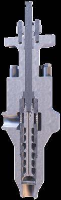
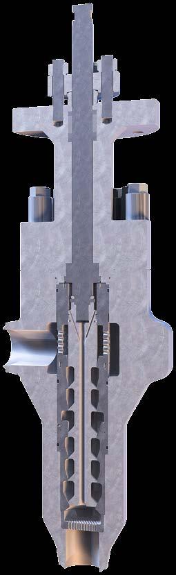
13 2.3 SCHROEDAHL ARV Types SUL Type Max. Class 300 / PN 64 Cast Body Economic and Efficient Design TDL Type Max. Class 300 / PN 64 Forged Body Check Valve in the Bypass Venturi Ring Design TDM Type Max. Class 1500/2500 / PN 250/400 Forged Body High Pressure Reduction Bypas Device (up to 5 Stages) Non return Function in Bypass MRK/MRM Type Max. Class 4500 / PN 640 Forged Body High Pressure Reduction Bypass System for Pressure Reduction up to 500 bar. 9
14 2.4. The ARV Functioning / Flow Curve Modulating Bypass Function All SCHROEDAHL valves have a modulating function; they do not have a simple ON / OFF function. Therefore, with the modulating function, they can handle load cases between zero process flow and the minimum pump operating conditions without loss of energy. During zero process flow, the bypass is completely open. The pump is running with the specified minimum flow. When increasing the process flow, the bypass flow will decrease accordingly , ,900 Main Flow in m 3 /h Switch Point SP P 0,700 0,500 0,300 Pressure Drop in bar R Bypass 0,100 Bypass Flow Pump Flow P Process Flow R 0 Pressure Drop 0% 10% 20% 30% 40% 50% 60% 70% 80% 90% 100% Lift of Check Valve in % Example curve with design conditions: Above flow curve shows the valve behavior for the flow reduction process (shut-down event). Q100 % = 100 m 3 /h Qmin = 30 m 3 /h Valve switch point (SP) For normal operation conditions with TDM-Valves, where the bypass flow is not higher than about 30 % of the rated pump flow, the valve switch point is about 25 % higher than the specified minimum flow: SP ~ Qm x 1.25 This very low switch point is one of the advantages of SCHROEDAHL valves! 10
15 2.5 ARV Operation on Pump Curve Please refer to the following principal pump curve to understand the characteristics of an ARV according to the typical pump curve (pressure head over pump flow). Q vs. H [in%] 180 % 160 % Normal Operation Range Pump Head in % 140 % 120 % 100 % 80 % 60 % Minimum Flow Point PM [QM; HM] Valve Bypass Switch Point SP Rated Point P100 [Q100; H100] 40 % 20 % 0 % 0 % 20 % 40 % 60 % 80 % 100 % 120 % 140 % Pump Flow in % H [%] Design Points Valve Switch Point Definition For the curve, the normal operation point (rated point) is stated as the 100 % case with H= 100 % at Q= 100 % Explanation The bypass flow will decrease when the flow to the system (process flow) is increased. Therefore, the bypass flow reduces from the minimum flow point to the switch point. At the ARV switch point, the bypass flow is closed. Usually, the system operation is between 40 % to 100 % and therefore above the valve switch point (see graph above: normal operation). Operation Range of Pump Protection HP applications, which should operate from 0 % to 100 % process flow, require detailed engineering and have to be confirned before order processing (see section 2.1). 11
16 2.6. ARV Application with Speed Operated Pumps 3900 Q Vs. H Max. Speed Curve Head - Metres Line of Minimum Pump Flow Min. Speed Curve Flow - m 3 /h Picture: Typical Speed Operated Pump Curve The ARV is flow sensitive As the ARV functioning is related only to the process flow quantity, the valve will not have a problem when it must operate at lower pump speeds / lower pump pressures. This is a very big advantage of the ARV solution compared with a Control Valve system. Valve calculation For the valve design we calculate / incorporate all given speeds with its minimum flow points and will ensure that all different operation points are covered (worst case scenario). The ARV pump protection will have a large and sufficient operational range. The ARV is able to handle speed operated pumps easily! Note: Please also inform us about the load data if a booster pump with constant speed is installed. 12
17 2.7 Engineering Guideline for ARV s Materials Standard temperature range from -196 C to +260 C (LP up to +400 C) Standard sealing material is EPDM, NBR, FKM, FFKM SUL valves are available in CS and SS housing material only (cast body) TD, MRM and MRK valves: CS, SS, LT, Duplex, Super Duplex Special materials on request! Differential Pressure at Rated Flow The differential pressure at rated flow (based on normal medium velocities of 4 to 5 m/s): SUL approx. 0.3 bar TDL approx. 0.4 bar TDM approx. 1.0 bar (approximate figures, depending on load conditions) Installation Conditions Preferred vertical, horizontal on request. Preferred installation is directly on pump discharge flange, otherwise, if possible, no farther downstream than about 3 metres after the pump (depends on application). Standard filter mesh size should be 0.3 to 0.5 mm (pump suction side). For commissioning we recommend a smaller filter size of 0.1 mm. Examinations, Tests and Certificates Standard certificates acc. EN / 3.1 and 97/23/EG (PED for CE-Marking for Europe). Leakage: Main Check Valve: FCI 70.2 Class IV (all valves) Bypass: FCI 70.2 Class IV (only TDM / MRM valves); TDL and SUL are not tight closing (LP application). Witnessed inspection by customer or third party inspection. Non-destructive examinations on request for TD, MRM and MRK series (not for SUL type). Bypass Kv Value test certificate, on request. Flow curve for TDM, MRM and MRK series, on request. 13
18 2.8 ARV Data Sheet for Communication and RFQ Automatic Recirculation Valve RFQ Datasheet Client: Customer Ref.: TAG No.: Qty.: Project: System Description: Valve Inlet DN PN Flange Standard (DIN EN/ ASME;..): Valve Outlet DN Installation: (vertical = standard) Bypass DN Painting: (Stand./ Spec.) Manual Start-Up (if req.) DN Certificates: (e.g. EN / 3.1,...) Specification/ Specials/ NDT Requirements: Carbon Steel, Stainless Steel, Duplex, others: Housing Material: Medium: Operating Temperature: C S.G.: in kg/dm³, t/m³ Design Temperature: C Design Pressure: bar g Q 100 = m 3 /h H 100 = m Suction Pressure p V : bar g Q max = m 3 /h H 0 = m Back Pressure Bypass p N : bar g Q M = m 3 /h H M = m Back Pressure Start-up p A : bar g Q A = m 3 /h H A = m Head H in m H O H M H 50 H 100 H Qmax Q M Normal range Q max Mainflow Q in % Q A Operatingpoint Manualstart-up on request p 1 p A Q p 2 p N Bypass Q min Pump Suction tank Q p V 14
19
20 2016 XYQOM GmbH / rev. 2016_UK_004 SCHROEDAHL GmbH Alte Schönenbacher Str Reichshof-Mittelagger GERMANY Phone Fax schroedahl@circor.com
Installation, maintenance, assembly and operating manual for minimum flow valves of type TDM
 Page 1 of 41 Installation, maintenance, assembly and operating manual for minimum flow valves of BA-TDM-01-EN Version: 05.2017 Page 2 of 41 Content 1 General... 4 1.1 Customer service and procedure when
Installation, maintenance, assembly and operating manual for minimum flow valves of type TDL
 Page 1 of 33 Installation, maintenance, assembly and BA-TDL-01-EN Version: 05.2017 Page 2 of 33 Content 1 General... 4 1.1 Customer service and procedure when servicing... 4 1.2 About this manual... 4
Pressure reducing valves Index
 Index General information page Introduction 506 General introduction 507 for a steam plant 509 Product information BSP thread page Brass 510 ; BSP female thread 511 ; BSP male thread 513 Stainless steel
Pressure and/or Temperature Pilot Operated Steam Regulators Series 2000
 Hoffman Specialty Regulators Regulators Pressure and/or Temperature Operated Regulators Series 2000 The Hoffman Specialty Series 2000 consists of main valves, pilot valves, wells and hardware kits. They
BACK PRESSURE / SUSTAINING
 In many liquid piping systems, it is vital that line pressure is maintained within relatively narrow limits. This is the function of the 108 Pressure Relief / Back Pressure Series of the OCV control valves.
BACK PRESSURE / SUSTAINING
 SPECIFICATIONS DIMENSIONS In many liquid piping systems, it is vital that line pressure is maintained within relatively narrow limits. This is the function of the 108 Pressure Relief / Back Pressure Series
OIL SUPPLY SYSTEMS ABOVE 45kW OUTPUT 4.1 Oil Supply
 OIL SUPPLY SYSTEMS ABOVE 45kW OUTPUT 4.1 Oil Supply 4.1.1 General The primary function of a system for handling fuel oil is to transfer oil from the storage tank to the oil burner at specified conditions
NAF-Trimball Control Ball Valves
 NAF-Trimball Control Ball Valves Size DN 50-500, Size 2-20 PN 10 40, ANSI Class 150 and 300 Fk 41.65(9)GB 11.04 Primary characteristics The NAF-Trimball represents an entirely new approach for addressing
BERMAD Waterworks. Level Control Valve with Altitude Pilot. 700 Series. Model X. Features and Benefits. Major Additional Features
 Level Control Valve with Altitude Pilot High level reservoirs & water towers Energy cost critical systems Systems with poor water quality Inherent refreshing Level sustaining at reservoir outlet The Level
Model TB 3-16 TECHNICAL BULLETIN. Secure-Gard Pilot Operated Vent Valve (POVV) BENEFITS TYPICAL APPLICATIONS FEATURES
 BENEFITS TYPICAL APPLICATIONS FEATURES") TECHNICAL BULLETIN 1049 - TB 3-16 Model 1049 Secure-Gard Pilot Operated Vent Valve (POVV) ISO Registered Company The Model 1049 is a pilot operated vent valve specifically designed for low-pressure storage
TECHNICAL BULLETIN 1049 - TB 3-16 Model 1049 Secure-Gard Pilot Operated Vent Valve (POVV) ISO Registered Company The Model 1049 is a pilot operated vent valve specifically designed for low-pressure storage
FILTER BYPASS CONTROL
 Differential Control Valve Series 110 The Series 110 Differential Control Valve is designed to accurately control the pressure difference between any two points. In some systems this means the valve remains
Paul Ladage 26 September 2017 MOVING THINGS AROUND - LATEST TRENDS IN HONEYWELL FLAGSHIP REGULATORS
 Paul Ladage 26 September 2017 MOVING THINGS AROUND - LATEST TRENDS IN HONEYWELL FLAGSHIP REGULATORS Agenda 1 What do we sell? Flagship Products HON 5020 HON R100 NG HON 512, class 150 Q&A Where Do Honeywell
DN300 DN2000 C Plunger Valve
 ל DN300 DN2000 C Plunger Valve P.O.B 46 MOSHAV SHTULA WESTERN GALILEE 2286500 Tl. +972-(0)77-6656101, Fax. +972-(0)77-6656196 Website: www.saisanketvalves.com www.saisanket.com email: saisanket@saisanket.com
Series 42 Self-operated Regulators Differential Pressure Regulators with Type 2424/Type 2428 Actuator (closing) Type Type 42-28
 Type Type 42-28") Series 42 Self-operated Regulators Differential Pressure Regulators with Type 2424/Type 2428 Actuator (closing) and balanced Type 2422 Valve Type 42-24 Type 42-28 Application Differential pressure regulators
Series 42 Self-operated Regulators Differential Pressure Regulators with Type 2424/Type 2428 Actuator (closing) and balanced Type 2422 Valve Type 42-24 Type 42-28 Application Differential pressure regulators
Pressure and Flow Control Valves DBGM, German and European Patents
 Pressure and Flow Control Valves DBGM, German and European Patents Absolutely Reliable Pressure and Flow Control In water mains of sizes DN 50 to DN 150, ERHARD Control Valves in straight or angle pattern
Pressure Independent Control Series
 Document No. 155-522 Pressure Independent Control Series Two-Way Cast Iron Flanged Bodies, ANSI 125 and 250 Description Siemens Pressure Independent Control Valves integrate three functions into a single
SINGLE VALVE WITH LOW-FLOW BYPASS
 CONTROL VALVES Pressure Reducing Valve Sizing Guide Sizing pilot operated reducing valves is not a complicated process. It starts with determining requirements and following these guidelines in valve size
94270 Vapor Guard Tank Blanketing Valve Vapor Guard Tank Blanketing Valve What is Tank Blanketing? Features How does it work?
 94270 What is Tank Blanketing? blanketing systems are used to prevent the escape of liquid vapors into the atmosphere or to prevent moisture from entering a tank and contaminating its contents. A tank
2/2-Way Solenoid Control Valve
 2/2-Way Solenoid Control Valve Excellent range (1:200) Very good response Compact valve design Orifice sizes 0.05... 2.0 mm Port connection 1/8 or sub-base Type 2871 can be combined with Type 8605 Digital
T 2523 EN Type 2406 Excess Pressure Valve Self-operated Pressure Regulators ANSI version
 T 2523 EN Type 2406 Excess Pressure Valve Self-operated Pressure Regulators ANSI version Application Excess pressure valve for set points from 0.075 to 150 psi (5 mbar to 10 bar) Valve size NPS ½ to 2
Gas Pressure Regulator HON 200
 Product information serving the gas industry worldwide Applications, characteristics, technical data Application Gas supply to municipal, industrial and individual consumers Regulator for low-load rails
6301 TYPE CAST IRON SAFETY VALVES
 Pressure (bar) 6301 TYPE CAST IRON SAFETY VALVES FEATURES The 6301 type safety valve is a device designed to protect installations against possible overpressure. It operates automatically and closes when
Chapter 10: Bidirectional Flow Controls
 Chapter 10: Bidirectional Flow Controls Objectives Learn about the patented, bidirectional flow control valves. Understand how the flow force affects the performance of the ZL70-36. Learn why there is
KSB Delta Compact Type Series Booklet
 Pressure Booster System KSB Delta Compact Type Series Booklet Legal information/copyright Type Series Booklet KSB Delta Compact All rights reserved. The contents provided herein must neither be distributed,
G type DUCTED EXHAUST SAFETY VALVE 2871 AND 288X SERIES. Model/Ref:
 Model/Ref: 28713 www.lauridsenindustri.com CHARACTERISTICS The G type safety valves are dedicated to protect the equipment from potential overpressure. They are automatic and close when the pressure conditions
FOAM TANK (1/2) DATA SHEET
 DATA SHEET") FIRE FIGHTING EQUIPMENT DATA SHEET FOAM TANK (1/2) DATA SHEET JOB NO. : RFQ. NO. : ISSUE : SHEET OF 01 CUSTOMER : ITEM NO. : 02 PROJECT : QUANTITY : 03 LOCATION : SERVICE : FOAM SYSTEM 04 05 CODE & STANDARDS
FIRE FIGHTING EQUIPMENT DATA SHEET FOAM TANK (1/2) DATA SHEET JOB NO. : RFQ. NO. : ISSUE : SHEET OF 01 CUSTOMER : ITEM NO. : 02 PROJECT : QUANTITY : 03 LOCATION : SERVICE : FOAM SYSTEM 04 05 CODE & STANDARDS
V311. Venta. Three-way Plug Valve, Flanged PN 16
 1 Three-way Plug Valve, Flanged PN 16 can be used in a wide range of applications, such as heating, cooling, air handling and domestic hot water systems. Soft EPDM seals provide tight shut off. The valve
Mounting and Operating Instructions EB 3007 EN. Self-operated Pressure Regulators. Differential Pressure Regulators (opening) Type Type 42-25
 Type Type 42-25") Self-operated Pressure Regulators Differential Pressure Regulators (opening) Type 42-20 Type 42-25 Type 42-20 Differential Pressure Regulator Type 42-25 Differential Pressure Regulator Mounting and Operating
Self-operated Pressure Regulators Differential Pressure Regulators (opening) Type 42-20 Type 42-25 Type 42-20 Differential Pressure Regulator Type 42-25 Differential Pressure Regulator Mounting and Operating
PRESSURE REDUCING VALVE RP45 (EN)
") PRESSURE REDUCING VALVE RP45 (EN) DESCRIPTION The ADCA RP45 series pressure reducing valves are single seat bellows sealed controllers, operating without auxiliary energy, designed for use on steam, compressed
PRESSURE REDUCING VALVE RP45 (EN) DESCRIPTION The ADCA RP45 series pressure reducing valves are single seat bellows sealed controllers, operating without auxiliary energy, designed for use on steam, compressed
Self-operated Pressure Regulators Type 2405 Pressure Reducing Valve
 Self-operated Pressure Regulators Type 2405 Pressure Reducing Valve ANSI version Application Pressure reducing valve for set points from 0.075 to 150 psi (5 mbar to 10 bar) Valve size NPS ½ to 2 1) (DN
2-step solenoid valve Type ICLX
 Data sheet 2-step solenoid valve ICLX 32-150 ICLX 2-step solenoid valves belong to the ICV family. ICLX are used in suction lines for the opening against high differential pressure, e.g. after hot gas
Installation, maintenance, assembly and operating manual for back pressure regulator type BPV
 manual for back pressure regulator type BPV Page 1 of 30 Installation, maintenance, assembly and operating manual for back pressure regulator type BPV BA-BPV-01-EN Version: 01.2018 manual for back pressure
The Shand & Jurs Model Vapor Guard Tank Blanketing Valve
 Lower maintenance due to fewer parts Occupies less space, less stress to tank Teflon is inert to most chemicals; extends service life Simplifies and lowers maintenance cost Optimizes flow of blanketing
Materials : Carbon steel ASTM A216 WCB
 Certificate 3.1 Size : Ends : Min Temperature : Max Temperature : DN 50 to DN 400 ( NPS 2" to 16" ) Flanges R.F. Class 150 (PN20) - 29 C + 425 C Max Pressure : 20 Bars Specifications : Removable stainless
CAST IRON SAFETY VALVE TYPE 6301
 CHARACTERISTICS The 6301 safety valve is dedicated to protect the equipment from potential overpressure. This is an automatic device that closes when the pressure conditions are back to normal. It is a
FOAM TANK (1/2) DATA SHEET
 DATA SHEET") FIRE FIGHTING EQUIPMENT DATA SHEET FOAM TANK (1/) DATA SHEET JOB NO. : RFQ. NO. : ISSUE : SHEET OF 01 CUSTOMER : ITEM NO. : 0 PROJECT : QUANTITY : 0 LOCATION : SERVICE : FOAM SYSTEM 0 05 CODE & STANDARDS
FIRE FIGHTING EQUIPMENT DATA SHEET FOAM TANK (1/) DATA SHEET JOB NO. : RFQ. NO. : ISSUE : SHEET OF 01 CUSTOMER : ITEM NO. : 0 PROJECT : QUANTITY : 0 LOCATION : SERVICE : FOAM SYSTEM 0 05 CODE & STANDARDS
Rate of Flow Valve Series 120
 SPECIFICATIONS Rate of Flow Valve Series DIMENSIONS The OCV Series 120 Rate of Flow control valve is designed to control or limit flow to a predetermined rate, regardless offl uctuations in downstream
CALEFFI. Ball zone valves. series /03 GB
 all zone valves series cert. n ISO / Function Zone valves are used to automatically shut-off the flow of carrier fluid distributed to a system. Specifically: -In central heating systems, they support the
Automatic Balancing Valve Pressure difference controller with integrated flow limiter AB-PM DN
 Data sheet Automatic Balancing Valve Pressure difference controller with integrated flow limiter AB-PM DN 40-100 Description AB-PM is ideal for staged installation and commissioning AB-PM is a combined
Pilot HON 625. Entwurf. Product information. serving the gas industry worldwide
 Pilot HON 62 Entwurf Product information serving the gas industry worldwide Pilot HON 62 Application, characteristics Application Pilot for the gas pressure regulator HON 02 Pilot for outlet pressure control
E 328 E 498 Tank top mounting Connection up to G1½ / -24 SAE and SAE 2 Nominal flow rate up to 600 l/min / gpm
 Return-Suction Filters E 8 E 98 Tank top mounting Connection up to G½ / - SE and SE Nominal flow rate up to 6 l/min / 8. gpm Description pplication For operation in units with hydrostatic drives, when
VB-7323 Series. Application. Features. Applicable Literature. 1/2 to 2 Screwed NPT Three-Way Diverting Valves General Instructions
 VB-7323 Series 1/2 to 2 Screwed NPT Three-Way Diverting Valves General Instructions Application VB-7323 series three-way diverting valves control hot or chilled water in heating or air conditioning systems.
Materials : Stainless steel ASTM A351 CF8M
 Certificat 3.1 Size: Ends : Min Temperature : Max Temperature : DN 15 to DN 200 PN16 Flanges R.F. - 20 C + 200 C Max Pressure : 16 Bars Specifiations : Removable stainless steel filter Bolted bonnet with
VB-7212 Series. Application. Features. Applicable Literature. 5/8" O.D., 45 SAE Flared Stem Up Open, Two-Way Valves General Instructions
 VB-7212 Series 5/8" O.D., 45 SAE Flared Stem Up Open, Two-Way Valves General Instructions Application VB-7212 series single seat, stem up open, two-way valves control water from 20 to 281 F (-7 to 138
Self-operated Pressure Regulators Type 2405 Pressure Reducing Valve
 Self-operated Pressure Regulators Type 2405 Pressure Reducing Valve Application Pressure reducing valve for set points from 5 mbar to 10 bar Nominal size DN 15 to 50 Nominal pressure PN 16 to 40 Suitable
Versions. Benefits. Balancing DN15-32 DN40 DN50 DN15, DN20, DN25, DN32, DN40, DN50. Dimensions
 Ballorex Delta Description The Ballorex Delta is a differential pressure control valve used in hydronic heating or cooling systems. By ensuring a constant differential pressure across motorized or static
POP Safety Valve. POP Safety Valve INTRODUCTION DEFINITIONS
 POP Safety Valve POP Safety Valve INTRODUCTION The effects of exceeding safe pressure levels in an unprotected pressure vessel or system, can have catastrophic effects on both plant and personnel. Safety
PILOT OPERATED RELIEF VALVE SAFETY PRODUCTS THAT PROTECT EQUIPMENT, LIVES & THE ENVIRONMENT
 PILOT OPERATED RELIEF VALVE SAFETY PRODUCTS THAT PROTECT EQUIPMENT, LIVES & THE ENVIRONMENT Model Number Model Description Page # Pilot operated Relief Valves Pilot Operated Relief Valves 3-27 Operation
2-step solenoid valve Type ICLX
 Data sheet 2-step solenoid valve ICLX 32-150 ICLX 2-step solenoid valves belong to the ICV family. ICLX are used in suction lines to open against high differential pressure, e.g. after a hot gas defrost
Pressure Reducing Valve DMV 750
 ASV Stübbe GmbH & Co. KG Hollwieser Straße 5 D-32602 Vlotho Fon +49 (0) 57 33-7 99-0 Fax +49 (0) 57 33-7 99-2 00 www.asv-stuebbe.de contact@asv-stuebbe.de Pressure Reducing Valve DMV 750 Advantages reduction
2-port and 3-port seat valves, PN16
 s 4 47 VVI47 VXI47 CVTIX 2-port and 3-port seat valves, PN6 with internally threaded connections VVI47.. VXI47.. ronze valve body CC49K (Rg5) DN 5...5 k vs 2.5...4 m 3 /h Internally threaded connections
Hydronic Systems Balance
 Hydronic Systems Balance Balancing Is Misunderstood Balancing is application of fundamental hydronic system math Balance Adjustment of friction loss location Adjustment of pump to requirements By definition:
KSB Delta Compact Type Series Booklet
 Pressure Booster System KSB Delta Compact Type Series Booklet Legal information/copyright Type Series Booklet KSB Delta Compact All rights reserved. The contents provided herein must neither be distributed,
Model MTB-ASME Vertical Bladder Tanks
 DATA SHEET Model MTB-ASME Vertical Bladder Tanks Features n UL Listed for use with various proportioners and foam concentrates n 175 psi (12.1 bar) maximum allowable working pressure (design pressure)
Mass Flow Controller (MFC) for Gases
 for Gases") Mass Flow Controller (MFC) for Gases Bypass MFC with capillary technology for nominal flow rates from 5 ml N /min to 15 l N /min Applicable for aggressive gases Compact design and digital communication
Mass Flow Controller (MFC) for Gases Bypass MFC with capillary technology for nominal flow rates from 5 ml N /min to 15 l N /min Applicable for aggressive gases Compact design and digital communication
Technote. Frese ALPHA cartridges. Application. Features. Benefits.
 Page 1 of 7 Application is used in heating and cooling systems for the distribution of flow in various sections of the system. The dynamic balancing valve ensures easy and reliable balancing of the system,
Safety Shut-Off Valve HON 720
 Safety Shut-Off Valve HON 70 Product information serving the gas industry worldwide Application, Characteristics, Technical Data Application main safety device for gas pressure regulating stations suitable
Gas Pressure Regulator HON 300
 Product information serving the gas industry worldwide Applications, characteristics, technical data Applications direct acting gas pressure regulator, for systems in accordance with DVGW working instruction
Pressure Reducing Valve DMV 750 set range: bar
 Pressure Reducing Valve DMV 750 set range:.0-6.0 bar Advantage pressure setting possible at any time, also during operation hermetically sealed by valve diaphragm high level of operating safety and long
Safety shut-off valve Control Control Lock-up Over pressure set point Under pressure set point pressure range accuracy class
 MR HP20 Gas pressure regulator Inlet pressure 20 bar Nominal diameter DN 25, DN 50, DN 80, DN 100 Applications Pressure reduction for: - District distribution - Industrial uses Brief information The gas
Model MTB-ASME Vertical Bladder Tanks
 DATA SHEET Model MTB-ASME Vertical Bladder Tanks Features n UL Listed for use with various proportioners and foam concentrates n 175 psi (12.1 bar) maximum allowable working pressure (design pressure)
Size : Ends : Min Temperature : Max Temperature : Materials : Cast iron body
 Size : Ends : Min Temperature : Max Temperature : DN 15 to DN 400 Flanges GN10/16-10 C + 120 C Max Pressure : 16 Bars up to DN 200 ( 10 bars over ) Specifications : Removable stainless steel filter Bolted
TECHNICAL DATA. Page 1 of 12
 Page 1 of 12 1. DESCRIPTION The Viking Regulating Valve is a direct-acting, single-seated, spring-loaded diaphragm valve. When installed as a pilot regulating valve on a Viking Model H or J Flow Control
Ball Float Steam Trap UNA 43 PN 16/CL 125/JIS 10K UNA 46 PN 40/CL 150/CL 300/JIS 10K/JIS 20K DN 80, 100, 150, 3", 4", 6"
 Data Sheet 819584-00 Issue Date: 01/17 Ball Float Steam Trap UNA 43 PN 16/C 125/JIS 10K UNA 46 PN 40/C 150/C 300/JIS 10K/JIS 20K DN 80, 100, 150, 3", 4", 6" UNA 43 hl, UNA 46 hl UNA 43 v, UNA 46 v with
Overview of types. T5-R B2/R B2 en v Subject to changes 1 / 4. k vs (Sequence 2)
") Technical data sheet R3015-..-..-B2 / R3020-..-..-B2 Characterised control valves, 6-way, with internal threads Two sequences (cooling/heating) With a rotary actuator 90 Water-side switching or modulating
Technical data sheet R3015-..-..-B2 / R3020-..-..-B2 Characterised control valves, 6-way, with internal threads Two sequences (cooling/heating) With a rotary actuator 90 Water-side switching or modulating
Mass Flow Controller (MFC) for Gases
 for Gases") Mass Flow Controller (MFC) for Gases Type 8713 can be combined with... Direct flow measurement by MEMS- Technology for nominal flow rates from 1 ml N /min to 8 l N /min (N 2 ) High accuracy and repeatability
Mass Flow Controller (MFC) for Gases Type 8713 can be combined with... Direct flow measurement by MEMS- Technology for nominal flow rates from 1 ml N /min to 8 l N /min (N 2 ) High accuracy and repeatability
CASH VALVE TYPE KP BACK PRESSURE VALVES
 A high capacity pilot operated back pressure valve that offers accurate control and dependable protection against overpressure conditions FEATURES Automatically maintains maximum pressure in a vessel or
E 328 E 498 Tank top mounting Connection up to G1½ and SAE 2 Nominal flow rate up to 600 l/min
 Return-Suction Filters E 8 E 98 Tank top mounting Connection up to G½ and SE Nominal flow rate up to 6 l/min Description pplication For operation in units with hydrostatic drives, when the return flow
TECHNICAL DATA Q= C. Table 1 - Specifications
 September 25, 2013 Pressure Regulation 537a 1. Description The Model B-3 Pilot Operated Pressure Control Valve is a factory assembled unit. The unit consists of a Model J-2 Halar coated Flow Control Valve,
safety Shut-Off Valve HON 721
 safety Shut-Off Valve HON 7 product information serving the gas industry worldwide safety shut-off valve HON 7 safety shut-off valve HON 7 Application, Characteristics, Technical Data Application safety
3-port seat valves with externally threaded connection, PN 16
 4 463 Acvatix 3-port seat valves with externally threaded connection, PN 16 VXG41.. ronze CuSn5Zn5Pb2 valve body DN 15 50 k vs 1.6 40 m 3 /h Flat sealing connections with external thread G to ISO 228-1
Serie 06-M6. Swing wafer check valve. made in. Application fields. Check valves E U R O P E WATER CONDITIONING INDUSTRY
 Swing wafer check valve BRANDONI made in E U R O P E Application fields WATER CONDITIONING INDUSTRY HEATING 38 www.brandoni.it The valves in series 06 are swing wafer check valves, manufactured in accordance
Solenoid Valves, one - or two step, on/off ICLX
 MAKING MODERN LIVING POSSIBLE Technical brochure Solenoid Valves, one - or two step, on/off ICLX 32-150 ICLX servo valves belong to the ICV (Industrial Control Valve) family. ICLX are used in suction lines
TECHNICAL DATA CAUTION
 Page 1 of 12 1. DESCRIPTION The Viking Model C-2 Pilot Pressure Regulating Valve is a direct-acting, single-seated, spring-loaded diaphragm valve. When installed as a pilot regulating valve on a Viking
2-Port Seat Valves with Flange, PN 16
 4 45 2-Port Seat Valves with Flange, PN 6 VVF45... dular cast iron EN-GJS-400-5 valve body DN 50...50 k vs 9...00 m /h Can be equipped with SKB...- or SKC...- electrohydraulic actuators Use For use in
E 158 E 198 E 248. Tank top mounting Connection up to G11 / 4 Nominal flow rate up to 250 l/min e d
 R e t u r n - S u c t i o n F i l t e rs E 158 E 198 E 248 Tank top mounting Connection up to G11 / 4 Nominal flow rate up to 250 l/min 20.90-5e 0.0-2d D e s c r i p t i o n Application For operation in
Ball Float Steam Trap UNA 45 MAX, UNA 46 MAX, UNA 46A MAX PN 40/Class 300 DN 40, 50, 65
 Data Sheet 819346-02 Issue Date: 05/17 Ball Float Steam Trap UNA 45 MAX, UNA 46 MAX, UNA 46A MAX PN 40/Class 300, 50, 65 UNA 45hl MAX, UNA 46hl MAX, UNA 46Ahl MAX UNA 45v MAX with cover for mounting electrode
VPPL VARIABLE DISPLACEMENT AXIAL-PISTON PUMPS FOR INTERMEDIATE PRESSURE SERIES 10
 / ED VPPL VARIABLE DISPLACEMENT AXIAL-PISTON PUMPS FOR INTERMEDIATE PRESSURE SERIES OPERATING PRINCIPLE The VPPL are variable displacement axial-piston pumps with variable swash plate, suitable for applications
Size : Ends : Min Temperature : Max Temperature : Materials : Cast iron body
 Size : Ends : Min Temperature : Max Temperature : DN 40 to DN 300 Flanges R.F. PN10/16-10 C + 80 C Max Pressure : 16 Bars up to DN200 Specifications : Removable stainless steel filter Bolted bonnet with
V5001P. Kombi-Auto Differential Pressure Control Valve. Product specification sheet
 V5001P Kombi-Auto Differential Pressure Control Valve Product specification sheet Content Application...1 Special Features...1 Valve Efficiency...1 Technical Data...2 Construction...2 Materials...2 Method
PTF4 Pivotrol Pump (patented) version Dual Mechanism - Pressure Powered Pump
 version Dual Mechanism - Pressure Powered Pump") Local regulations may restrict the use of this product to below the conditions quoted. In the interests of development and improvement of the product, we reserve the right to change the specification without
Local regulations may restrict the use of this product to below the conditions quoted. In the interests of development and improvement of the product, we reserve the right to change the specification without
Tank Blanketing Pressure Regulators RHPS Series
 www.swagelok.com Tank Blanketing Pressure Regulators RHPS Series Types: pressure reducing and vapor recovery 16L stainless steel construction 1/2, 1, and 2 in. end connections Working pressures up to 22
HYDRAULIC CONTROL VALVES
 HYDRAULIC CONTROL VALVES INC. VALVES, INC HYDRAULIC CONTROL VALVES WORKING PRINCIPALS It is automatic hydraulic control valve designed for make desired modulation processes in main valve network line as
Horizontal Bladder Tanks
 DATA SHEET Horizontal Bladder Tanks Features UL Listed and FM Approved for use with various ANSUL proportioners and foam concentrates 175 psi (12.1 bar) maximum allowable working pressure (design pressure)
MFP14-PPU (Vented) Automatic Packaged Pump Units
 Automatic Packaged Pump Units") 681060/2 IM-P681-02 ST Issue 2 MFP14-PPU (ented) Automatic Packaged Pump Units Installation and Maintenance Instructions 1. Safety information 2. General product information 3. Single MFP14 - PPU installation
681060/2 IM-P681-02 ST Issue 2 MFP14-PPU (ented) Automatic Packaged Pump Units Installation and Maintenance Instructions 1. Safety information 2. General product information 3. Single MFP14 - PPU installation
Vertical Bladder Tanks
 DATA SHEET Vertical Bladder Tanks Features UL Listed and FM Approved for use with various ANSUL proportioners and foam concentrates 175 psi (12.1 bar) maximum allowable working pressure (design pressure)
Differential Pressure Control Valve (DPCV)
") Differential Pressure Control Valve (DPCV) PATENTED Technical Data and Installation Instructions Page 1 V2 The modulating valves ART 241 balance and control the differential pressure (DPCV) automatically
Differential Pressure Control Valve (DPCV) PATENTED Technical Data and Installation Instructions Page 1 V2 The modulating valves ART 241 balance and control the differential pressure (DPCV) automatically
MITIGATING PIPE AND RISER HYDRAULIC PIPELINE ISSUES WITH THE I-RISER PLUS
 24 TH July 2013 MITIGATING PIPE AND RISER HYDRAULIC PIPELINE ISSUES WITH THE I-RISER PLUS Vern Costelow Business Development Consultant AWMA Water Control Solutions INTRODUCTION Surface irrigation is still
Mounting and Operating Instructions EB 3009 EN. Self-operated Regulators. Type RS Check Valve (backflow protection)
") Self-operated Regulators Type 42-10 RS Check Valve (backflow protection) Type 42-10 RS Check Valve (backflow protection) Mounting and Operating Instructions EB 3009 EN Edition December 2015 Definition
Self-operated Regulators Type 42-10 RS Check Valve (backflow protection) Type 42-10 RS Check Valve (backflow protection) Mounting and Operating Instructions EB 3009 EN Edition December 2015 Definition
TECHNICAL DATA. Pressure Regulation 531a. April 24, 2009
 April 24, 29 Pressure Regulation 531a 1. DESCRIPTION The Viking Regulating Valve is a direct-acting, single-seated, spring-loaded diaphragm valve. When installed as a pilot regulating valve on a Viking
Product Sheet Pre-Fabricated Flushing Bypass Assembly for Terminal Applications Mini-Flush 40
 Product Sheet Pre-Fabricated Flushing Bypass Assembly for Terminal Applications Mini-Flush 40 Description Miniflush 40 is a pre-fabricated, flushing bypass arrangement for balance, control, isolation,
Model MTB-ASME Horizontal Bladder Tanks
 DATA SHEET Model MTB-ASME Horizontal Bladder Tanks Features n UL Listed and FM Approved for use with various proportioners and foam concentrates n 175 psi (12.1 bar) maximum allowable working pressure
VB-7213 Series. Application. Features. Applicable Literature. 1/2" to 2" Screwed NPT Stem Up Open, Two-Way Valves General Instructions
 VB-7213 Series 1/2" to 2" Screwed NPT Stem Up Open, Two-Way Valves General Instructions Application VB-7213 series single seat, stem up open, two-way valves control water from 20 to 281 F (-7 to 138 C)
Bermad Pressure Reducing. Model: 42T
 Bermad Pressure Reducing Pilot Operated Pressure Control Valve Model: 42T Installation Operation Maintenance Manual (IOM) REV. 27.7.17 Page 1 of 12 Safety First BERMAD believes that the safety of personnel
SCA Series Inverted Bucket Steam Traps
 0770050/5 IM-P077-06 ST Issue 5 SCA Series Inverted Bucket Steam Traps Installation and Maintenance Instructions 1. General safety information 2. General product information 3. Installation 4. Commissioning
Safety Shut-off Valve SSV
 Safety Shut-off Valve SSV 8200-8300 < Accurate operation < Compact design < Easy maintenance Applications The safety shut-off valve is designed for use in gas distribution, and pressure regulation systems.
Pressure Reducing Valve DMV 755
 Pressure Reducing Valve DMV 755 Nominal size DN 10 50 Nominal size 3/8 2 Nominal pressure PN 10 bar Features pressure setting range 1 to 9 bar control valve for reliable reduction of system pressures to
Ballorex Dynamic Description. Versions. Benefits. Balancing
 Ballorex Dynamic Description The Ballorex Dynamic valve is a combined pressure independent flow limiter and control valve which maintains a constant flow independently of pressure changes in heating or
2-Port Seat Valves with Flange, PN 16
 4 40 2-Port Seat Valves with Flange, PN 6 VVF4... Grey cast iron EN-GJL-250 valve body DN 50...50 k vs 9...00 m /h Can be equipped with SQX- electromotoric or SKD...-, SKB...- or SKC...- electrohydraulic
VERTICAL BLADDER TANK
 Balanced Pressure Proportioning System Reliable Foam System Requiring Only Water Power Perfect For Tight Spaces UL Listed, ASME, National Board Registered Bladder-UL162 Approved, High Tensile Pressure