0311T. General Installation and Maintenance Instructions
|
|
|
- Lionel Thompson
- 5 years ago
- Views:
Transcription

1 0311T General Installation and Maintenance Instructions
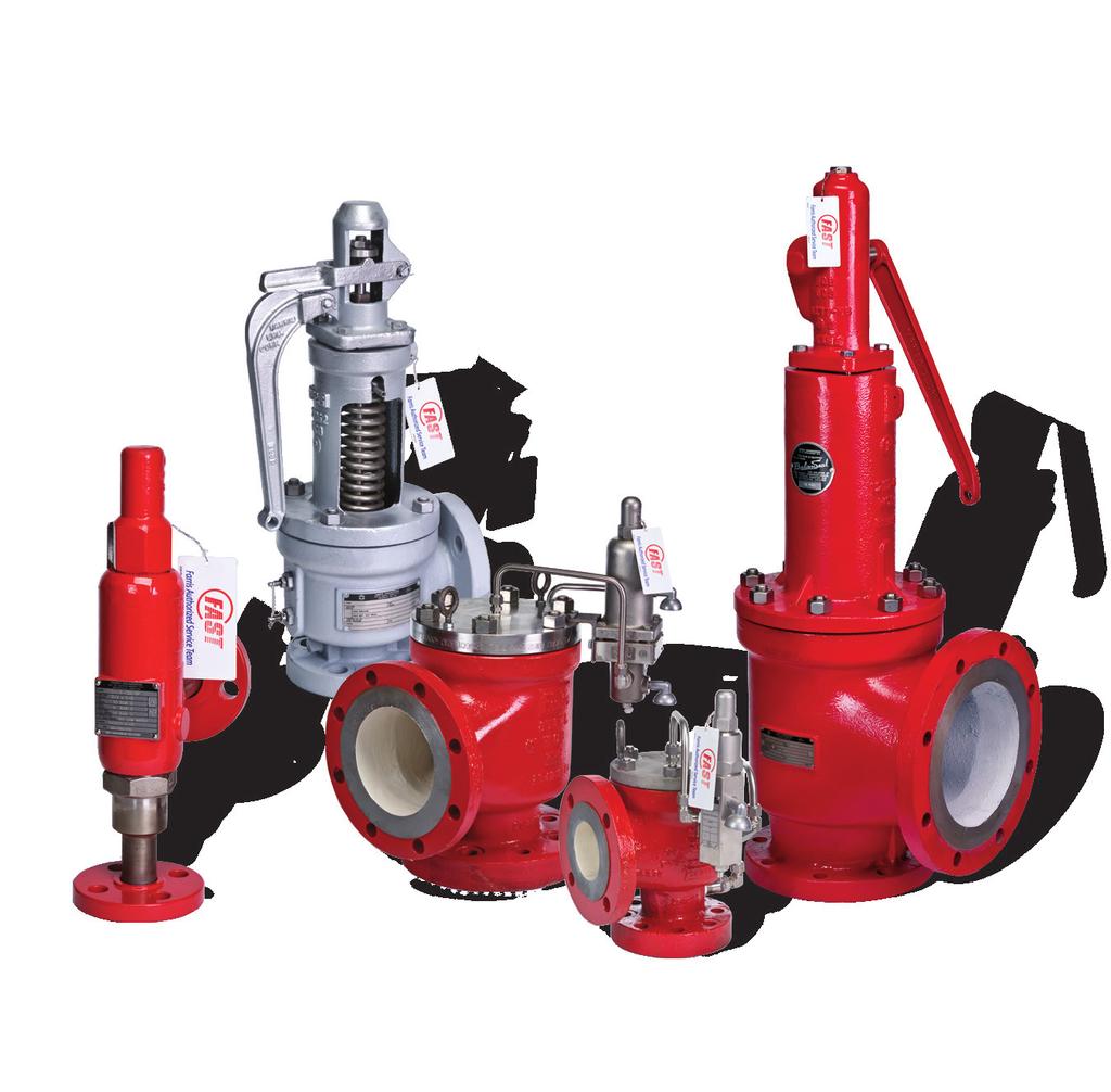
2 Table of Contents These maintenance and installation instructions are applicable to Farris Series 2600, 2700, 2850, 2856, 1890, 1896M, 3800, 4200 and 6400 pressure relief valves. Safety Warning & Instruction System...1 General Safety Instructions Introduction...3 Receiving Inspection, Storage & Handling...3 Installation Typical PRV Installation Schematic...4 Maintenance Basics...5 Valve Reference Drawings Pre-Installation Testing...3 Farris Product Line Scope Series ASME Certification Pressure Equipment Directive Section Test Fluids Code Symbol Compliance Directive Mark 2600 Section VIII Air, Steam & Water yes 2600L Section VIII Water & Air yes 2700 Section VIII Air, Steam & Water yes 3800 Section VIII Air, Steam & Water yes 4200 Sections I & VIII Air & Steam yes 6400 Sections I & VIII Air & Steam no 1890 Section VIII Air, Steam, & Water no V V 1896M Section VIII Air, Steam, & Water no Not Available 2850* Section VIII Air & Steam no 2856* Section VIII Air & Steam no *Available for non-asme code liquid applications. General Notes 1. All valves are stamped with the appropriate ASME Code V or UV stamp as noted above. 2. In addition to the appropriate ASME Code stamp, valves shipped into the European market are marked with the CE symbol indicating compliance with the Pressure Equipment Directive. 3. Valves may also be supplied to ASME Code Section III, NV stamp.
3 Safety Warning & Instruction System You will find safety warnings and instruction labels in this manual. These have been included to ensure your safety and must be followed. Safety labels are vertically oriented rectangles as shown in the samples below. These labels consist of three panels inside a border. Each safety label will communicate the following three key pieces of information using narrative and pictorials. The nature and severity of the hazard. The consequence of the hazard, if not avoided. The precautions and measures required to avoid the hazard. The top panel of the safety label illustrates the signal word (DANGER, WARNING, or CAUTION) which communicates the severity of the hazard, per the explanations to the right. The center panel contains a pictorial which communicates the nature of the hazard, and the possible consequence of hazard if not avoided. In some cases, the pictorial may depict the precautions or measures required to avoid the hazard. The bottom panel will then contain the remaining narrative information needed to ensure all three key pieces of information have been conveyed. DANGER Content included here will describe the nature of the dangerous condition and/or how to prevent the danger hazard from occurring. WARNING Content included here will describe the nature of the warning condition and/or how to prevent the warning hazard from occurring. CAUTION Content included here will describe the nature of the caution condition and/or how to prevent the caution hazard from occurring. Content included here will describe instructions regarding how to prevent property, product or environmental harm. SAFETY INSTRUCTIONS Content included here will describe processes or procedures which ensure safety if properly followed. DANGER: Indicates hazards which, if not avoided, will result in serious injury or death. WARNING: Indicates hazards which, if not avoided, could result in serious injury or death. CAUTION: Indicates hazards which, if not avoided, could result in minor or moderate injury. : is reserved for instructions given to prevent property, product, or environmental harm. SAFETY INSTRUCTIONS: SAFETY INSTRUCTIONS indicates processes or procedures recommended to ensure safety. General Safety Instructions These general installation and maintenance instructions are provided by Farris Engineering to its customers as general guidance for the handling, storage, and installation of Farris valves. Pressure relief valves are critical components in pressurized systems that ensure the safety of personnel and property. Always follow all manufacturer and industry standard recommendations relating to proper installation, testing, maintenance, and reconditioning. This should not be considered an exhaustive manual and it does not cover the full maintenance and repair of valves. Certain configurations, applications, and usages may not be covered. All information presented in this manual is subject to change without notice. If there is specific information needed that is not covered in this manual, the customer is advised to contact Farris. The purchaser should also contact Farris regarding any possible changes in information or specifications. Please use the contact information on the back of this manual. To ensure reliable and safe operation of Farris valves, installation, testing, maintenance, adjustment, and repair shall only be performed by qualified personnel having the required skills and training. No repair, assembly, adjustment or testing performed by individuals other than Farris-authorized representatives shall be covered by the warranty extended by Farris to its customers. All applicable regulations, directives, codes and standards shall be adhered to when performing these activities. Failure to follow proper test procedures or failure to use proper test equipment will lead to incorrect test results, damage to the valve and will invalidate the warranty. Likewise, use of parts in any maintenance or repair activity other than factory-supplied OEM parts will invalidate the warranty extended by Farris to its customers. Incorrect selection or application of Farris valves on the part of the customer is not covered by the warranty extended by Farris to its customers. These general instructions have been provided not only to ensure the proper installation and maintenance of Farris pressure relief valves, but also to provide for the safety of personnel who handle our products. Failure to follow these procedures could result in severe bodily harm or even death. 1
4 General Safety Instructions, cont. All possible hazards may not be identified in this manual. Conduct your own safety risk assessment given your specific system, environment, and configuration, and ensure proper control procedures are in place to prevent personal injury or illness and property, product or environmental harm. DANGER When the valve is under pressure, do not place any part of your body near or in the path of the outlet of the main valve or other discharge areas. Doing so will result in serious injury or death upon valve discharge. If a test gag is provided with the valve, it must be removed prior to installation. Failure to do so will result in equipment failure, serious injury or death in the instance of an overpressure event. WARNING Never attempt to remove, adjust, maintain, or repair a pressure relief valve while it is installed in a pressurized system unless you have been properly trained to do so. Doing so may result in serious injury or death. Ensure proper isolation of any energy sources and residual pressures by complying with all local, state and country-specific regulations/ directives applying to energy control procedures (lockout/tagout). Ensure that the pressure relief valve and system is at an ambient temperature before inspecting, servicing, or repairing. The valve, system, and contents may be extremely hot or cold. Failure do so may result in serious injury. The discharge from the main valve outlet or any other vents, should be piped or vented to a safe location to eliminate the potential for serious injury or damage during relief operation. To ensure the valve is free to operate, check the inlet and outlet piping for potential obstructions which may exist as a result of process fluid solidification, polymerization or other system problems. Failure to do so could render the valve inoperable, leading to serious injuries or damage in the event of system over-pressurization. Use extreme caution when inspecting a pressure relief valve for leakage. Always stay clear of the valve outlet during seat leakage testing as the valve can suddenly open fully causing serious injury. Doing so could result in serious burn, chemical or injection injury. Use all appropriate personal protective equipment to protect against process hazards, including but not limited to, pressurization, temperature extremes, noise, and chemical hazards. Failure to do so could result in serious injury or death. CAUTION Always use the appropriate tools, and in the correct manner, for adjustment or servicing of valves. Failure to do so could result in injury. SAFETY INSTRUCTIONS It is the responsibility of the customer and user of Farris valves to properly train their personnel on all required maintenance procedures and safety standards to prevent injuries. Farris can provide comprehensive training on the maintenance and repair of all Farris products. Contact your local Farris representative or the factory. Improper handling, storage, installation and maintenance of a PRV can cause damage to the valve and will invalidate the warranty. Please follow all recommended procedures. Prior to valve disassembly, ensure that proper controls are implemented to address potential exposures to hazardous substances, including gases, liquids, or process byproducts contained in or contaminating the valve. Consult applicable material safety data sheets (MSDSs) and established exposure limits for the substances expected to be present to ensure proper exposure controls are implemented. Failure to do so could result in serious injury or illness. 2
5 Introduction These installation and maintenance instructions WARNING are being provided to ensure the proper installation, repair and safe operation of Farris pressure relief valves. Pressure relief valves are precision instruments and should only be installed and repaired by personnel who have been properly trained and qualified to provide this service. Correct installation is essential for plant, property, personnel and public safety. Failure of a pressure relief valve can lead to catastrophic overpressure of equipment and/or the release of effluent under pressure. Effluent may be hazardous and all precautions should be taken to ensure safe disposal. Receiving Inspection, Storage & Handling Cleanliness is essential to WARNING the satisfactory operation and tightness of a pressure relief valve. Prior to installation the following practices should be followed: Upon receipt, look for any shipping damage. Inspect packaging for evidence that the valve has been tipped over or dropped. Failure to inspect, store and handle the PRV can cause improper functioning of the valve. Please read and follow these instructions. Verify the nameplate data against ordering documents. Confirm that factory wire seals are in place and not broken. If it appears that the wire seal has been broken, the name plate information does not match documentation, or if the packaging or valve appear to have been damaged in transit, please contact your local Farris representative. Inlet & outlet covers should be left in place until the valve is installed. Valves should be moved and installed with the stem upright, in the vertical position. Note: Pilot operated relief valves should never be lifted or handled using the tubing, piping, pilot, or pilot brackets. Use the lifting eyes provided on the main valve body to move the valve. Care should be taken to keep the inlet and outlet clean and free of foreign material. Valves that are not immediately installed in service should be stored indoors, in the original container and in an area free of dirt and other contamination. The storage area should be at normal temperatures (50 to 100 F / 10 to 38 C). Pre-Installation Testing Before installation, it is important to confirm the set pressure and seat tightness. This testing should only be performed by trained and qualified personnel using proper test equipment. When performing pre-installation testing please note the following: Testing must only be performed using the correct test fluids. Air, gas and vapor service valves must be tested using air as the test fluid. Liquid service valves should be tested on water and steam service valves must be tested on steam. Note: For pilot operated relief valves on liquid service, introducing liquid into the dome area of the main valve and pilot assembly during pre-installation testing may later cause problems when the valve is placed into service. An air test may be substituted to confirm valve functions, but set pressures may vary from actual setting due to the difference in test media. Set pressure testing must be performed first, followed by seat leakage testing. Seat leakage testing is performed at 90% of set pressure. For valves set at 50 psig (3.45 barg) or below, the test pressure is 5 psig (0.35 barg) below the set pressure. If qualified personnel and proper test equipment are not available the pre-installation testing should be skipped. Installation Failure to follow proper test procedures or to use proper test equipment will lead to incorrect test results, damage to the valve and will void the warranty. Pressure relief valve performance can be WARNING adversely affected by improper installation. To ensure good performance and safe operation of the valve these guidelines should be followed. Failure to do so could result in valve failure, serious injury or death. Pressure relief valves may contain sharp surfaces. Proper personal protective equipment (PPE) should be used. Before installing a valve, depressurize the system. Always install valves upright with the stem in the vertical position and the inlet at the bottom. Remove the optional test gag, if supplied. Install valves close to the pressure source so that inlet pressure loss is no more than 3% of set pressure. To avoid reducing the valve s actual capacity, be sure piping connected to the valve s inlet/outlet connections is equal to or larger than the valve connections. Avoid installing valves close to equipment that can cause pressure fluctuations, such as compressor discharge lines. 3
6 Install valves away from equipment that may cause turbulence, such as reducing stations, orifice plates/nozzles, and other valves and fittings. Make sure all inlet and outlet piping is properly supported to avoid putting excessive load on the valve. Provide drainage from the discharge piping or valve body. On valves with bellows, remove plastic shipping plugs from the bonnet and vent in a safe direction. Do not pipe bonnet vents to a pressurized system that would introduce backpressure. Clean inlet and outlet flange surfaces and valve interior cavity to remove rust inhibitors. Remove the inlet and outlet flange protectors and any extraneous packing or documentation materials inside the valve body or nozzle. Test levers are provided on some valves to allow the user to manually verify that the valve trim is free to move. Test levers should only be pulled when system pressure is greater than 75% of set pressure in order to avoid potential damage to the valve. In addition the valve should never be carried by the test lever as this can move the disc off the seat resulting in damage to both parts. Tighten all inlet and outlet flange bolts evenly. Leave enough room to allow for in-line maintenance and adjustments. Additional Instructions for Pilot Valve: Pilot valves are equipped with bug vent(s) on the pilot control bonnet and/or body. Check to be sure vents have not been plugged. The pilot control discharge is vented to atmosphere since the volume released when the valve opens is small. If a release to atmosphere is not permitted, then vent the discharge to a safe location. Do not pipe discharge to a pressurized system that would introduce backpressure unless it is a balanced pilot control design. On pilot valves supplied with field test connections, remove the plastic shipping plug from the isolation valve and assure that it is partially open. System Start Up and Testing: It is recommended that the valve be isolated during pressure testing of the system either by blanking, closing a stop valve or using a test tag. If a test gag is used, exercise extreme caution to avoid damaging the valve stem or seat by over tightening the gag screw. Gag screws should be installed hand tight and should always be removed after system testing has been completed. Remove the optional test gag, if supplied. Valve will not function with test gag in place. Typical PRV Installation API RP 520, Part II Installation Support to resist weight and reaction forces Pressure relief valve Body drain Pressure drop not more than 3% of set pressure Long radius elbow Vessel Cap may be required for weather protection If connected to a closed system, specific care should be taken to keep piping strains away from the pressure relief valve under all conditions of process operation. Support to resist weight and reaction forces Pressure relief valve Body drain Pressure drop not more than 3% of set pressure Long radius elbow Vessel Cap may be required for weather protection If connected to a closed system, specific care should be taken to keep piping strains away from the pressure relief valve under all conditions of process operation. Stop valve preferably should have full round port area and be equal to or greater than the inlet size of the pressure relief valve. This stop valve should be used only as permitted in the applicable codes. 4 Recommended Typical Pressure Relief Valve Installation Without Shutoff Valve Recommended Typical Pressure Relief Valve Installation With Shutoff Valve Figure 1.1 Figure 1.2
7 Maintenance Basics Pressure relief valve maintenance should only WARNING be performed by trained and qualified personnel using proper test equipment. Repairs by unqualified personnel or use of improper test equipment may lead to poor valve performance. These basic instructions apply to all Farris valve series. They do not provide information specific to product lines. For more detailed maintenance instructions, please consult the appropriate manuals for the valve under consideration. As a general rule, these procedures apply to all pressure relief valves: Proper personal protective equipment (PPE) should be used. Before repairing or servicing a valve, depressurize the system. For valves, that have been in service, a review of the material safety data sheet (MSDS) of process effluent should be done prior to disassembly. Proper controls should be in place to address potential exposures to hazardous substances, including gases, liquids, process media, or process by-products contained in the valve. External surfaces of the valve, including flange face surfaces and threaded connections, should be examined for any signs of damage or rough handling. Completely disassemble the valve and thoroughly clean all parts. Parts should be examined for signs of corrosion or excessive wear. Particular attention should be given to ensure all threads are clean and free of burrs. Examine the stem to ensure it is straight. Lap the nozzle seat and disc seating surfaces to a flat mirror finish. Reassemble valve making sure to lubricate all OEM parts only! threaded and bearing surfaces. Standard repair procedure requires that all gaskets and soft goods such as O-ring seals be replaced with new parts. This section is for general guidance only. Please consult appropriate product line specific manuals for detailed maintenance instruction. Failure to use Farris OEM parts can create dangerous operating conditions, poor valve performance and will void the warranty. Valve should be calibrated to the set pressure indicated on the nameplate unless a new pressure is required. When the set pressure is being changed maintenance personnel must confirm if the existing spring is acceptable or if a new spring is required. Testing must only be performed using the correct test fluids. Air, gas and vapor service valves must be tested using air as the test fluid, liquid service valves should be tested on water, and steam service valves must be tested on steam. Note: For pilot operated relief valves on liquid service, introducing liquid into the dome area of the main valve and pilot assembly during maintenance testing may cause problems when placed in service. The setting and testing of the pilot control may be done separately from the main valve on the proper fluid. An air test may be substituted to confirm valve functions, but set pressures may vary from actual setting due to the difference in test media. Set pressure testing must be performed first, followed by seat leakage testing. Seat leakage testing is performed at 90% of set pressure. For valves set at 50 psig (3.45 barg) or below, the test pressure is 5 psig (0.35 barg) below the set pressure. After the repair has been completed, all external adjustments should be wire-sealed to prevent tampering. Inlet and outlet openings should be sealed until the valve is ready for installation in order to prevent foreign material from entering the valve. 5

8 Farris Valve 2600 Series cap bonnet stem Figure 1.6 BalanSeal Bellows Safety Valve Note: Bonnet vent must be open on bellows design. disc body blow down ring nozzle 6 direction of flow
9 Farris Valve 2700 Series cap bonnet stem disc body 7 direction of flow

10 Farris Valve 3800 Series cover pilot control discharge vent piston 3800 Series Snap-Acting Control nozzle body 3800 Series Main Valve bonnet vent 8 discharge vent 3800 Series Modulating Control direction of flow
 stem disc")


11 Farris Valves 4200, 6400/6600 Series Steam Valves cap lever bonnet (open) stem disc adjusting ring body nozzle 4200 Series 6400 Series Farris Valves 1890/1896, 2850/2856 Series cap bonnet stem disc blow down ring body & 1896M Series 2850 & 2856 Series direction of flow


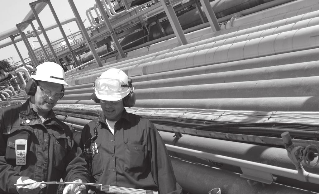
12 Farris Aftermarket Services Real Value Behind Every Valve. Farris Engineering s aftermarket department and global FAST Center Network adds value to every Farris valve. At Farris, our work is never done. Once we sell you a valve, our FAST Team is there to keep your valves in service and your plant safe. Our FAST Centers are: Responsive. Farris Engineering and its FAST Centers understand the need to quickly and efficiently respond to customer needs. Global Access - FAST Centers work with and in our extensive representative network, providing support to all global regions. 24/7 Valve Service and Replacement - FAST Centers offer quick, localized testing and repair of valves, or the prompt installation of new Farris ASME certified valves. Mobile Repair Units - Available at select FAST Centers. Experienced. Farris Engineering recognizes the value of having pressure relief valve experts as close to the customer as possible. This is accomplished through comprehensive training offered at the factory or on-site. FAST Center sales personnel and technicians are able to provide valuable experience to their customers. Valve Expertise - Every FAST Center is technically supported by Farris Engineering, a leader in valve design. Factory Trained Technicians - FAST technicians go through mandatory training consisting of classroom lecture and hands-on practical instruction on Farris Engineering pressure relief valves, repair procedures and applicable codes and standards. The result is a team of highly skilled technicians capable of handling both routine and complex pressure relief valve requirements around the world. OEM parts - FAST Centers use only OEM parts, restoring valves to OEM specifications. All valves are assembled and tested to ASME standards. Dedicated. FAST Centers have committed to large investments in inventory, equipment and certifications to better support the customers in their territory. Local Inventory - Every FAST Center carries a large inventory of new pressure relief valves and spare parts, backed by a web-based global inventory to draw from. ASME Certification - FAST Centers carry all the required certifications to assemble, set and test Farris valves. VR Certification - FAST Centers have VR certification issued by The National Board of Boiler and Pressure Vessel Inspectors to effectively and efficiently repair all pressure relief valves where applicable. Farris Authorized Service Team Responsive. Experienced. Dedicated. Farris Engineering Curtiss-Wright Flow Control Phone: (440) V NV Brecksville Road, Brecksville, OH USA Telephone: Fax: Facilities: Brecksville, Ohio, USA; Brantford, Ontario, Edmonton, Alberta, Canada; Corby, Northants, UK; Delhi, India; Tianjin, Beijing, China; Dubai, U.A.E. Offices Worldwide: For a listing of our global sales network, visit our website at While this information is presented in good faith and believed to be accurate, Farris Engineering, division of Curtiss-Wright Flow Control Corporation, does not guarantee satisfactory results from reliance on such information. Nothing contained herein is to be construed as a warranty or guarantee, expressed or implied, regarding the performance, merchantability, fitness or any other matter with respect to the products, nor as a recommendation to use any product or process in conflict with any patent. Farris Engineering, division of Curtiss-Wright Flow Control Corporation, reserves the right, without notice, to alter or improve the designs or specifications of the products described herein Farris Engineering Printed in U.S.A. 0311T 01/14 25M R3
SAPAG. Safety valves, type 5700 Storage, Use, Operation and Maintenance Instructions. IMPORTANT NOTICE
 SAPAG IMPORTANT NOTICE Contents Important notice 1 0 Valve identification 2 1 Storage 2 2 Installation 2 3 Operation 2 4 Maintenance 3 4.1 Dismantling 3 4.2 Inspection 3 4.3 Repair 3 4.4 Assembly 4 4.5
Type S301 & S302 Gas Regulators INTRODUCTION INSTALLATION. Scope of Manual. Description. Specifications. Type S301 and S302. Instruction Manual
 Fisher Controls Instruction Manual Type S301 & S302 Gas Regulators October 1981 Form 5180 WARNING Fisher regulators must be installed, operated, and maintained in accordance with federal, state, and local
Atmospheric relief valve type 1100 Installation and maintenance instructions
 SAPAG 1. Description Sapag atmospheric relief valves type 1100 have been selected for installation because of their performance features, reliability and ease of maintenance. They are designed to protect
ANDERSON GREENWOOD SERIES 9000 POSRV INSTALLATION AND MAINTENANCE INSTRUCTIONS
 Procedure-assembly-functional test and performance requirements 1 SCOPE 1.1 This document establishes the general procedure for assembly, functional testing and normal performance requirements of low Series
The flow direction must be observed during installation. It can be recognized by the following features: Flow direction. Gasket
 6.2 Installation of the Safety Valve The correct installation within a plant is essential for the proper operation of a safety valve. Installation in this sense is e.g. - the choice of the gaskets - the
Manual Actuated Boiler Blowdown Valves
 Manual Actuated Boiler Blowdown Valves Installation and Maintenance Instructions 1. Safety information 2. General product information 3. Installation 4. Operation 5. Maintenance 6. Spare parts p.1 1. Safety
COMMITTEE DRAFT. API 520 Part I 10 th Edition Ballot Item 2.1. This ballot covers the following item:
 This ballot covers the following item: API 520 Part I 10 th Edition Ballot Item 2.1 2008 12 Modify guidance to PRV datasheets (Line 17) to assist user s with determining the temperature to use for selecting
29 SERIES - SAFETY VALVE
 INDUSTRIES, INC. 29 SERIES - SAFETY VALVE INSTALLATION, OPERATION, & MAINTENANCE Part I Document Number: ES1016-1 Revision Level: A Issued By: David Edmonds Date: 6/20/04 Approved By: Date: 10/4/04 Conbraco
Type 1367 High-Pressure Instrument Supply System with Overpressure Protection
 Instruction Manual D100343X012 Type 1367 November 2017 Type 1367 High-Pressure Instrument Supply System with Overpressure Protection TYPE 252 FILTER 2ND-STAGE TYPE 67CF FILTER-STYLE REGULATOR INLET TYPE
What is pressure relief valve? Pressure relief valve
 What is pressure relief valve? Pressure relief valve What is: Relief valve Safety valve Safety relief valve Type of pressure relief valve Pressure relief valve sizing base What are the sizing basis of
ANDERSON GREENWOOD. Provides reliable overpressure protection in a cost effective package. Flow Control
 ANDERSON GREENWOOD Provides reliable overpressure protection in a cost effective package. Product Overview Anderson Greenwood s LCP Series pilot operated safety valve is designed to provide the reliable
INSTALLATION, MAINTENANCE & OPERATING INSTRUCTIONS 2-4 REDUCED PORT/ FULL PORT (5700/6700) ANSI CLASS 150/300/600/900/1500/2500 TRUNNION BALL VALVES
 ANSI CLASS 150/300/600/900/1500/2500 TRUNNION BALL VALVES") PBV-USA,Inc. 12735 Dairy Ashford. Stafford, Texas USA 77477 281-340-5400; 800-256-6193 FAX: 281-340-5499 INDUSTRIAL BALL VALVES IM0 69 April 2001 Rev 9 INSTALLATION, MAINTENANCE & OPERATING INSTRUCTIONS
PBV-USA,Inc. 12735 Dairy Ashford. Stafford, Texas USA 77477 281-340-5400; 800-256-6193 FAX: 281-340-5499 INDUSTRIAL BALL VALVES IM0 69 April 2001 Rev 9 INSTALLATION, MAINTENANCE & OPERATING INSTRUCTIONS
TITAN FLOW CONTROL, INC.
 PREFACE: This manual contains information concerning the installation, operation, and maintenance of Titan Flow Control (Titan FCI) Simplex Basket Strainers. To ensure efficient and safe operation of Titan
WHEATLEY Series 500 Swing Check Valve
 Document Number: TC003001-13 Revision: 02 WHEATLEY Series 500 Swing Check Valve Installation, Operation, and Maintenance Manual TABLE OF CONTENTS BILL OF MATERIALS...3 SCOPE...5 INSTALLATION AND OPERATION
Apollo Standard Port, Full Port & One Piece Flanged Ball Valves Installation, Operation, & Maintenance Manual
 I854000.D Apollo Standard Port, Full Port & One Piece Flanged Ball Valves Installation, Operation, & Maintenance Manual Introduction This manual presents guidelines for the Installation, Operation and
PV4 and PV6 Piston Valves
 1181250/1 IM-P118-05 ST Issue 1 PV4 and PV6 Piston Valves Installation and Maintenance Instructions 1. Safety information 2. General product information 3. Installation 4. Commissioning 5. Operation 6.
756 Safety Relief Valves
 756 S a fe t y R e l i e f Va l ve s INTRODUCTION 756 Safety Relief Valves The effects of exceeding safe pressure levels in an unprotected pressure vessel or system, can have catastrophic effects on both
SERIES SAFETY VALVE
 R Manufactured by Conbraco Industries, Inc. 10-600 SERIES SAFETY VALVE INSTALLATION, OPERATION, & MAINTENANCE Part I Document Number: ES-1325 Revision Level: B Issued By: T.HAMILTON Date: 3/3/16 Approved
PROCEDURES FOR REPAIRS TO ASME NV STAMPED PRESSURE RELIEF DEVICES OF NUCLEAR SAFETY RELATED PRESSURE RELIEF VALVES
 NB16 0603 NR Task Group 1 9 16 1. One update by NR task group page 3: 7/17/19 2. Two updates to S6.1 and S6.3 on page 1: 7/19/17 SUPPLEMENT 6 PROCEDURES FOR REPAIRS TO ASME NV STAMPED PRESSURE RELIEF DEVICES
CAST IRON SAFETY VALVE TYPE 6301
 CHARACTERISTICS The 6301 safety valve is dedicated to protect the equipment from potential overpressure. This is an automatic device that closes when the pressure conditions are back to normal. It is a
299H Series. Introduction. P.E.D. Categories. Specifications. Installation. Warning. Installation Guide English September 2012
 Installation Guide English September 2012 299H Series Introduction This Installation Guide provides instructions for installation, startup, and adjustment of 299H Series regulators. To receive a copy of
WHEATLEY WHEATLEY SERIES 500 SWING CHECK VALVE. Installation, Operation and Maintenance Manual
 WHEATLEY SERIES 500 SWING CHECK VALVE STANDARD INTEGRAL SEAT & OPTIONAL REMOVABLE SEAT 2" FP - 6" FP 150# - 1500# 8" FP - 12" FP 150# - 900# API 6D and B16.34 2" FP - 4" FP 5000# DRILLING PRODUCTION VALVE
FV Flash Vessel Installation and Maintenance Instructions
 4041050/5 IM-P404-10 EMM Issue 5 FV Flash Vessel Installation and Maintenance Instructions 1. Safety information 2. Specific product safety information 3. Product information 4. Installation 5. Commissioning
FUNDAMENTALS OF PRESSURE RELIEF VALVES IN NATURAL GAS INSTALLATION - OPERATION - MAINTENANCE. Gary S. Beckett
 FUNDAMENTALS OF PRESSURE RELIEF VALVES IN NATURAL GAS INSTALLATION - OPERATION - MAINTENANCE Gary S. Beckett Flow Safe Supply 10727 Tower Oaks Boulevard Houston, Texas 77070 What Are They and Why Are They
776 Cryogenic Safety Valve
 776 Cryogenic Safety Valve INTRODUCTION 776 Cryogenic Safety Valve The effects of exceeding safe pressure levels in an unprotected pressure vessel or system, can have catastrophic effects on both plant
Mooney * Noise Controller Installation, Operation, and Maintenance Manual
 GE Oil & Gas Mooney * Noise Controller Installation, Operation, and Maintenance Manual imagination at work Scope This manual provides instructions for installation, operation and maintenance of the Mooney
Fisher DVI Desuperheater Venturi Inline
 Instruction Manual DVI Desuperheater Fisher DVI Desuperheater Venturi Inline Contents Introduction... 1 Scope of Manual... 1 Description... 1 Principle of Operation... 2 Installation... 3 Operating Instructions...
INSTALLATION, OPERATION, AND MAINTENANCE MANUAL WELKER RELIEF VALVE
 INSTALLATION, OPERATION, AND MAINTENANCE MANUAL WELKER RELIEF VALVE MODELS RV-1 RV-2 RV-2CP RV-3 DRAWING NUMBERS AD017A[ ] AD018A[ ] AD020A[ ] AD282BO MANUAL NUMBER IOM-033 REVISION Rev. E, 3/28/2016 TABLE
Installation Instructions
 Installation Instructions Durametallic MD-200 Series Gas Dual Cartridge Canister Seal for Mixers and Agitators Experience In Motion 1 Equipment Check 1.1 Follow plant safety regulations prior to equipment
1200B2 Series Service Regulators. Instruction Manual
 00B Series Service Regulators Instruction Manual 00B Series Service Regulators 0 Elster American Meter 00B Series Service Regulators General Information The 00B Series Service Regulators are available
2 Sentry MCL Installation, Operation & Maintenance
 Gas Liquid & Slurry Solid & Powder Steam & Water Installation, Operation & Maintenance Manual Original Instructions Liquid Sampling Manual Low-Emission Samplers S-GA-IOM-00249-7 11-17 Sentry MCL 966 Blue
Un-Pressurized Orefice Fittings FIO EZ. Parts List and Operation Instructions TECHNICAL MANUAL. Dn 2-6 Class Lbs
 Un-Pressurized Orefice Fittings FIO EZ Parts List and Operation Instructions TECHNICAL MANUAL Dn 2-6 Class 150-600 Lbs US US 2 FIO EZ - MT 108-US - 05-2016 FIO EZ Important Instructions US Pietro Fiorentini
WKM Model 320F Floating Ball Valve
 Date: 4 WKM Model 320F Floating Ball Valve Installation, Operation, and Maintenance Manual 1 Date: 4 All the information contained in this manual is the exclusive property of Cameron. Any reproduction
Installation Instructions
 Installation Instructions BW Seals Uniseal Series Cartridge metal bellows single and dual seals Experience In Motion Description The Uniseal metal bellows seal series consists of: Uniseal I - Single seals
POP Safety Valve. POP Safety Valve INTRODUCTION DEFINITIONS
 POP Safety Valve POP Safety Valve INTRODUCTION The effects of exceeding safe pressure levels in an unprotected pressure vessel or system, can have catastrophic effects on both plant and personnel. Safety
KBV21i and KBV40i Key Operated Boiler Blowdown Valves Installation and Maintenance Instructions
 4059051/3 IM-P405-48 EMM Issue 3 KBV21i and KBV40i Key Operated Boiler Blowdown Valves Installation and Maintenance Instructions 1. Safety information 2. General product information 3. Installation 4.
Installation Operation Maintenance
 682 Seal Cooler New generation seal cooler to meet and exceed the seal cooler requirements stated in the 4th Edition of API Standard 682 Installation Operation Maintenance Experience In Motion Description
Installation, Operation and Maintenance Manual for Back Pressure Regulator
 Installation, Operation and Maintenance Manual for Back Pressure Regulator Model 8860 2009 Groth Corporation IOM-8860 Rev. B 12541 Ref. ID: 95565 Page 2 of 13 Table of Contents I. INTRODUCTION 3 II. DESIGN
64 Series Pressure Reducing Regulators
 Instruction Manual Form 1245 64 Series March 2006 64 Series Pressure Reducing Regulators W1943 Figure 1. 64 Series Regulator Introduction Scope of Manual This manual provides instructions for the installation,
Float Operated Level Controllers
 CONTENTS Float Operated Level Controllers IM0015 Nov. 2014 PAGE Introduction 1 Scope 1 Description 1 Specification 1 Control Installation 2 INTRODUCTION Side Mount Back Mount Prior to installing, the instructions
INSTALLATION COMMISSIONING, OPERATION & MAINTENANCE MANUAL
 WedgeRock RW Series Worm Gear Actuators INSTALLATION COMMISSIONING, OPERATION & MAINTENANCE MANUAL Revision 01 Date 4/3/17 Page 1 Table of Contents 1.0 INTRODUCTION... 4 1.1 PURPOSE... 4 1.2 AUDIENCE...
FLANGED TWO-PIECE BALL VALVES
 INTRODUCTION This instruction manual includes installation, operation, and maintenance information for FNW flanged split-body ball valves. This manual addresses lever operated ball valves only. Please
EASTERN ENERGY SERVICES PTE LTD. 60 Kaki Bukit Place #02-19 Eunos Tech Park Singapore, SG Singapore Telephone: Fax:
 2 Table Of Contents 1. Introduction 3 2. About this Manual 3 3. Contacting YZ Systems 3 4. Vessel Components 4 5. Specifications 5 6. Application 6 7. Theory of Operation 7 8. DuraSite Installation & Use
Safety Valves. Expertise and solutions for steam, gas and liquid applications MECHANICAL SOLUTIONS
 Safety Valves Expertise and solutions for steam, gas and liquid applications MECHANICAL SOLUTIONS s a f e t y v a l v e s o l u t i o n s expert source for all your safety valve needs Spirax Sarco...the
RHPS Series RD(H)F40 User Manual. Read the complete manual before installing and using the regulator.
F40 User Manual. Read the complete manual before installing and using the regulator.") RHPS Series RD(H)F40 User Manual Read the complete manual before installing and using the regulator. 2 WARNING Before removing a regulator from the system for service, you must depressurize system purge
RHPS Series RD(H)F40 User Manual Read the complete manual before installing and using the regulator. 2 WARNING Before removing a regulator from the system for service, you must depressurize system purge
BUTTERFLY VALVES Series 800
 BUTTERFLY VALVES Series 800 WARNING Before proceeding read ALL instructions and become familiar with the equipment and associated drawings. Follow ALL applicable safety regulations and codes for pressurized
1800C and 1800C-HC Series Service Regulators
 1800C and 1800C-HC Series Service Regulators Installation Instructions www.elster-americanmeter.com General Information: The 1800C and 1800C-HC Regulators are available as Full Capacity Internal Relief
WHEATLEY Series 822/820 Swing Check Valve
 Document Number: TC003001-12 Revision: 02 WHEATLEY Series 822/820 Swing Check Valve Installation, Operation, and Maintenance Manual TABLE OF CONTENTS BILL OF MATERIALS...3 SCOPE...4 INSTALLATION AND OPERATION
INSTALLATION INSTRUCTIONS. CVS 67CFR Pressure Reducing Instrument Supply Regulator INTRODUCTION
 INSTALLATION INSTRUCTIONS CVS 67CFR Pressure Reducing Instrument Supply Regulator INTRODUCTION The CVS Controls 67CFR Filter regulator is a pressure reducing supply regulator typically used for pneumatic
Crosby style JCE Safety Valve Installation, Maintenance and Adjustment Instructions CROSBY
 CROSBY Table of contents 1. Installation 1 1.1. Drainage 1 1.2. Discharge pipework 1 1.3. Preparation for installation 1 2. Pressure adjustment 1 3. Maintenance 1 4. Dismantling 1 4.1. All valve types
6301 TYPE CAST IRON SAFETY VALVES
 Pressure (bar) 6301 TYPE CAST IRON SAFETY VALVES FEATURES The 6301 type safety valve is a device designed to protect installations against possible overpressure. It operates automatically and closes when
N2 Blanketing Valve DST100 / DST200 TYPE INSTRUCTION MANUAL CONTENTS K.S.P.C. General Description Operation. Installation Maintenance
 DST100 / DST200 TYPE N2 Blanketing Valve INSTRUCTION MANUAL CONTENTS General Description Operation Installation Maintenance K.S.P.C 488-1 Wolha-ro, Tongjin-eup, Gimpo-si, Gyeonggi-Do, Korea Tel : +82-31-998-3825~7
KTM OM-2 SPLIT BODY FLOATING BALL VALVES INSTALLATION AND MAINTENANCE INSTRUCTIONS
 Before installation these instructions must be fully read and understood SECTION 1 - STORAGE 1.1 Preparation and preservation for storage All valves should be properly packed in order to protect the parts
ROTATING DISK VALVES INSTALLATION AND MAINTENANCE 1. SCOPE 3 2. INFORMATION ON USAGE 3 3. VALVE TYPES 3 4. OPERATORS 5 5. VALVE CONSTRUCTION 6
 Sub Section INDEX Page Number 1. SCOPE 3 2. INFORMATION ON USAGE 3 3. VALVE TYPES 3 4. OPERATORS 5 5. VALVE CONSTRUCTION 6 6. INSTALLATION AND OPERATION 6 7. MAINTENANCE 8 8. REPAIR 9 9. ASSEMBLY 10 10.
Types S100K and S102K Pressure Regulators
 Instruction Manual Form 5624 Types S0K and S2K 01/01 Types S0K and S2K Pressure Regulators W7478-1 Figure 1. Types S0K and S2K Pressure Regulator Introduction Scope of Manual This manual provides instructions
FLANGED TWO-PIECE BALL VALVES
 INTRODUCTION This instruction manual includes installation, operation, and maintenance information for FNW flanged split-body ball valves. This manual addresses lever operated ball valves only. Please
SA121, SA122, SA123, SA128 and SA1219 Self-acting Temperature Control Systems (Dial Adjustment)
") 3820050/4 IM-P382-01 CH Issue 4 SA121, SA122, SA123, SA128 and SA1219 Self-acting Temperature Control Systems (Dial Adjustment) Installation and Maintenance Instructions 1. Safety information 2. Use 3.
3820050/4 IM-P382-01 CH Issue 4 SA121, SA122, SA123, SA128 and SA1219 Self-acting Temperature Control Systems (Dial Adjustment) Installation and Maintenance Instructions 1. Safety information 2. Use 3.
HAYWARD FLOW CONTROL Series PBV Back Pressure Valve and Series RPV Pressure Relief Valve INSTALLATION, OPERATION, AND MAINTENANCE INSTRUCTIONS
 HAYWARD FLOW CONTROL Series PBV Back Pressure Valve and Series RPV Pressure Relief Valve INSTALLATION, OPERATION, AND MAINTENANCE INSTRUCTIONS Page 1 of 20 Page 2 of 20 TABLE OF CONTENTS Safety Warnings
TESCOM 50-4X Series Safety, Installation & Start-Up Procedures
 Operations & Service Manual TESCOM 50-4X Series Safety, Installation & Start-Up Procedures Do not attempt to select, install, use or maintain this product until you have read and fully understood this
TA10A and TA10P Steam Tracing Temperature Control Valves Installation and Maintenance Instructions
 3500032/2 IM-P350-02 CH Issue 2 TA10A and TA10P Steam Tracing Temperature Control Valves Installation and Maintenance Instructions 1. Safety information 2. General product information 3. Installation 4.
Safety Selector Valves Dual Pressure Relief Device System
 ANDERSON GREENWOOD Features and enefits Provides a safe, efficient method of switching from an active pressure relief device to a standby, maintaining system overpressure protection regardless of Safety
Installation & Operation Manual Proven Quality since 1892
 Content 1. ERIKS operating companies 2. Product description 3. Requirements for maintenance staff 4. Transport and storage 5. Function 6. Application 7. Installation 8. Maintenance 9. Service and repair
KBV21i and KBV40i Air Actuated Boiler Blowdown Valves
 4059051/1 IM-P405-48 AB Issue 1 KBV21i and KBV40i Air Actuated Boiler Blowdown Valves Installation and Maintenance Instructions 1. Safety information 2. General product information 3. Installation 4. Commissioning
Anderson Greenwood Series 93 Positive Pressure POSRV Installation and Maintenance Instructions
 Before installation these instructions must be fully read and understood Installation and maintenance instructions for Series 93 Positive Pressure Pilot Operated Safety Relief Valves (POSRV). The intent
SALCO PRODUCTS, INC. PRESSURE RELIEF VALVE STORAGE, INSTALLATION, OPERATING, MAINTENANCE/TESTING, AND INSPECTION INSTRUCTIONS
 STORAGE INSTRUCTIONS Until it is time to install a new or reconditioned valve on the car, the valve must be kept in its original packaging in order to protect it from dirt and damage. INSTALLATION INSTRUCTIONS
Installation, Operating and Maintenance Instructions. V914 Cast Iron Flanged Swing Check Valve V914
 Installation, Operating and Maintenance Instructions V914 Cast Iron Flanged Swing Check Valve V914 THE PRESSURE EQUIPMENT DIRECTIVE 97/23/EC and CE MARKING The Pressure Equipment Regulations 1999 (SI 1999/2001)
G type DUCTED EXHAUST SAFETY VALVE 2871 AND 288X SERIES. Model/Ref:
 Model/Ref: 28713 www.lauridsenindustri.com CHARACTERISTICS The G type safety valves are dedicated to protect the equipment from potential overpressure. They are automatic and close when the pressure conditions
RD(H)20/25 Pressure-Reducing Regulator User Manual
20/25 Pressure-Reducing Regulator User Manual") RD(H)20/25 Pressure-Reducing Regulator User Manual Read the complete manual before installing and using the regulator. 2 Safe Product Selection When selecting a product, the total system design must be
RD(H)20/25 Pressure-Reducing Regulator User Manual Read the complete manual before installing and using the regulator. 2 Safe Product Selection When selecting a product, the total system design must be
THE BP-301 SERIES. Operating and Service Manual. Series includes all variants of BP-301 (LF 0.1Cv / MF 0.5Cv)
") THE BP-301 SERIES Operating and Service Manual Series includes all variants of BP-301 (LF 0.1Cv / MF 0.5Cv) Issue B October 2015 1 TABLE OF CONTENTS 1. Description... 3 2. Installation... 3 3. Operation...
THE BP-301 SERIES Operating and Service Manual Series includes all variants of BP-301 (LF 0.1Cv / MF 0.5Cv) Issue B October 2015 1 TABLE OF CONTENTS 1. Description... 3 2. Installation... 3 3. Operation...
Type ACE97. Introduction. Installation. P.E.D. Categories. Specifications. Overpressure Protection. Installation Guide English May 2002
 Installation Guide English May 2002 Type ACE97 Introduction This installation guide provides instructions for installation, startup, and adjustment. To receive a copy of the instruction manual, contact
MST21 Stainless Steel Balanced Pressure Thermostatic Steam Trap
 1250650/6 IM-P125-07 ST Issue 6 MST21 Stainless Steel Balanced Pressure Thermostatic Steam Trap Installation and Maintenance Instructions 1. Safety information 2. General product information 3. Installation
CROSBY STYLE JOS-E, JBS-E, JLT*-JBS-E, JLT*-JOS-E VALVES INSTALLATION AND MAINTENANCE INSTRUCTIONS
 Before installation these instructions must be read fully and understood TABLE OF CONTENTS 1 Introduction... 4 2 Storage and handling... 4 3 Installation... 4 4 Hydrostatic pressure tests... 5 5 Setting,
USER MANUAL. 1. Principle of operation. 2. Delivery condition. SPRING-LOADED SAFETY VALVES zarmak. Edition: 07/2016 Date: V (ex.
 ZETKAMA Sp. z o.o. ul. 3 Maja 12 PL 57-410 Ścinawka Średnia SPRING-LOADED SAFETY VALVES zarmak USER MANUAL 782V (ex. 782) Edition: 07/2016 Date: 01.07.2016 TABLE OF CONTENTS 1. Principle of operation 2.
SA121, SA122, SA123, SA128 and SA1219 Self-acting Temperature Control Systems (Knob Adjustment)
") 3810050/5 IM-P381-01 CH Issue 5 SA121, SA122, SA123, SA128 and SA1219 Self-acting Temperature Control Systems (Knob Adjustment) Installation and Maintenance Instructions 1. Safety information 2. Use 3.
3810050/5 IM-P381-01 CH Issue 5 SA121, SA122, SA123, SA128 and SA1219 Self-acting Temperature Control Systems (Knob Adjustment) Installation and Maintenance Instructions 1. Safety information 2. Use 3.
Eaton Filtration, LLC
 Eaton Filtration, LLC 900 Fairmount Avenue, Elizabeth, NJ 07207 Phone: 908-787-1000 Fax: 908-351-7893 E-Mail: filtration@eaton.com Web: www.filtration.eaton.com Installation, Operation & Service Manual
SV60 Safety valves. for use with steam, gas and liquids
 SV60 Safety valves for use with steam, gas and liquids Spirax Sarco safety valves - protecting people, plant and profit The SV60 spring loaded full lift safety valve range from Spirax Sarco has been designed
RS(H)10,15 USER MANUAL. Read the complete manual before installing and using the regulator.
10,15 USER MANUAL. Read the complete manual before installing and using the regulator.") RS(H)10,15 USER MANUAL Read the complete manual before installing and using the regulator. WARNING INCORRECT OR IMPROPER USE OF THIS PRODUCT CAN CAUSE SERIOUS PERSONAL INJURY AND PROPERTY DAMAGE. Due to
RS(H)10,15 USER MANUAL Read the complete manual before installing and using the regulator. WARNING INCORRECT OR IMPROPER USE OF THIS PRODUCT CAN CAUSE SERIOUS PERSONAL INJURY AND PROPERTY DAMAGE. Due to
TITAN FLOW CONTROL, INC.
 PREFACE: This manual contains information concerning the installation, operation, and maintenance of Titan Flow Control (Titan FCI) WYE Type Strainers. To ensure efficient and safe operation of Titan FCI
1805 Series Relief Valves
 Instruction Manual Form 1211 1805 Series October 2011 1805 Series Relief Valves! WARNING Failure to follow these instructions or to properly install and maintain this equipment could result in an explosion
Design DSA Steam-Atomized Desuperheater
 Instruction Manual DSA Desuperheater Design DSA Steam-Atomized Desuperheater Contents Introduction............................... 1 Scope of Manual......................... 1 Description..............................
Dri-Line Mk2 Spirax-Monnier Compressed Air Drain Trap
 0509950/2 IM-P050-21 CH Issue 2 Dri-Line Mk2 Spirax-Monnier Compressed Air Drain Trap Installation and Maintenance Instructions 1. Safety information 2. General product information 3. Installation and
RHPS Series PRV 6 User Manual
 RHPS Series PRV 6 User Manual Read the complete manual before installing and using the valve. 1 WARNING Before removing a valve from the system for service, you must depressurize system purge the system
Welcome to the LESER Seminar, Taipei 28. June Design_of_safety_relief_valves_250804_Cal
 Welcome to the LESER Seminar, Taipei 28. June 2006 1 Design of safety relief valves 2 Design of safety valves Target Classification of Pressure Relief Devices General design of Safety Relief valves 3 Design
Pressure Regulators. Operating Instructions. Instrumentation
 Pressure Regulators Operating Instructions FAILURE OR IMPROPER SELECTION OR IMPROPER USE OF THIS PRODUCT CAN CAUSE DEATH, PERSONAL INJURY AND PROPERTY DAMAGE. This document and other information from the
Fisher and Whisper Disk Diffusers
 Instruction Manual Inline and Vent Diffusers Fisher 6010 -- 6015 and Whisper Disk Diffusers Contents Introduction... 2 Scope of Manual... 2 Description... 2 Principle of Operation... 3 Piping Considerations...
FLANGED MULTI-PORT BALL VALVES
 INTRODUCTION This instruction manual includes installation, operation and maintenance information for flanged multi-port ball valves. This manual addresses lever operated ball valves only. Please refer
COSASCO 3600 PSI SINGLE ISOLATION SERVICE VALVE (FR) MAINTENANCE
 MAINTENANCE") COSASCO 3600 PSI SINGLE ISOLATION SERVICE VALVE (FR) MAINTENANCE Rohrback Cosasco Systems, Inc. 11841 E. Smith Avenue Santa Fe Springs, CA 90670 Tel: (562) 949-0123 (800) 635-6898 Fax: (562) 949-3065 www.cosasco.com
COSASCO 3600 PSI SINGLE ISOLATION SERVICE VALVE (FR) MAINTENANCE Rohrback Cosasco Systems, Inc. 11841 E. Smith Avenue Santa Fe Springs, CA 90670 Tel: (562) 949-0123 (800) 635-6898 Fax: (562) 949-3065 www.cosasco.com
INSTALLATION, OPERATION, AND MAINTENANCE MANUAL WELKER FILTER DRYER
 INSTALLATION, OPERATION, AND MAINTENANCE MANUAL WELKER FILTER DRYER MODEL F-4 DRAWING NUMBERS AD042C[ ] AD054C[ ] MANUAL NUMBER IOM-046 REVISION Rev. F, 4/23/2018 TABLE OF CONTENTS SAFETY 3 1. PRODUCT
1. Preface Important Safety Notes Brief Product Information Product Working Principle Installation Guidelines...
 Table of Contents 1. Preface...1 2. Important Safety Notes...1 3. Brief Product Information...3 4. Product Working Principle...5 5. Installation Guidelines...6 6. Startup and Commissioning...8 7. Maintenance
Model Secure-Gard Pilot Operated Vent Valve SECTION II. Remove all packing material inside and outside of the valve prior to installation.
 INSTALLATION, OPERATION AND MAINTENANCE MANUAL (IOM) IOM - 1049 01-17 Model 1049 Secure-Gard Pilot Operated Vent Valve ISO Registered Company SECTION I I. DESCRIPTION AND SCOPE The Model 1049 Secure-Gard
AIR DISTRIBUTOR. PART NUMBER (Including, but not inclusive) AD28483-_ALB, AD28563-_ALB, AD36097-_ALB, AD36098-_ALB, AD28485-_ALB
 AD28483-_ALB, AD28563-_ALB, AD36097-_ALB, AD36098-_ALB, AD28485-_ALB") Manual #: MM-AD001 12/5/11 Rev. A Page 1 of 8 PART NUMBER (Including, but not inclusive) AD28483-_ALB, AD28563-_ALB, AD36097-_ALB, AD36098-_ALB, AD28485-_ALB Manual #: MM-AD001 12/5/11 Rev. A Page 2 of
Manual #: MM-AD001 12/5/11 Rev. A Page 1 of 8 PART NUMBER (Including, but not inclusive) AD28483-_ALB, AD28563-_ALB, AD36097-_ALB, AD36098-_ALB, AD28485-_ALB Manual #: MM-AD001 12/5/11 Rev. A Page 2 of
Eaton Filtration, LLC
 Eaton Filtration, LLC 900 Fairmount Avenue, Elizabeth, NJ 07207 Phone: 908-787-1000 Fax: 908-351-7893 E-Mail: filtration@eaton.com Web: www.filtration.eaton.com Installation, Operation & Service Manual
OPERATING MANUAL. Contents. Bottom outlet ball valve Type ecoline
 OPERATING MANUAL Bottom outlet ball valve Type ecoline Contents 1 General Information 2 Safety 3 Packing, Handling, Storing 4 Product description 5 Preparation, Assembly 6 Commissioning 7 Handling 8 Attendance
Engineering Data Sheet
 Page 1 of 6 CE MARKING AND THE PRESSURE EQUIPMENT DIRECTIVE 97/23/EC Valves must be installed into a well designed system and it is recommended that the system be inspected in accordance with the appropriate
TECHNICAL DATA Q= C. Table 1 - Specifications
 September 25, 2013 Pressure Regulation 537a 1. Description The Model B-3 Pilot Operated Pressure Control Valve is a factory assembled unit. The unit consists of a Model J-2 Halar coated Flow Control Valve,
Dri-Line Mk3 Monnier Compressed Air Drain Trap
 5044050/2 IM-P504-24 CH Issue 2 Dri-Line Mk3 Monnier Compressed Air Drain Trap Installation and Maintenance Instructions 1. Safety information 2. General product information 3. Installation and Operation
GREIG FILTERS, INC. OPERATION MANUAL
 GREIG FILTERS, INC. OPERATION MANUAL MODEL DCFH 3P 15/3 100 S4 DOE/222 DUAL CARTRIDGE FILTER HOUSING TABLE OF CONTENTS I. INTRODUCTION II. CARTRIDGE FILTER HOUSING UNIT A. OPERATION B. INSTALLATION C.
VALVCHEQ BACKFLOW PREVENTERS FIGURE RP03
 Reduce pressure zone device suitable for high and medium hazard rated applications Flanged end connections FEATURES GENERAL APPLICATION The RP03 provides protection from both backsiphonage and backpressure
English. Introduction. Safety Instructions. All Products. Inspection and Maintenance Schedules. Parts Ordering. Specifications WARNING WARNING
 Contents All Products... Gb-1 Control Valves... Gb-2 Control Valve Actuators... Gb-3 Regulators... Gb-3 Relief Valves... Gb-4 Instruments, Switches, and Accessories... Gb-4 Products Covered by Battery
TECHNICAL DATA MAINTENANCE AIR COMPRESSOR MODEL G-1
 Dry 131h 1. DESCRIPTION The Viking Model G-1 Maintenance Air Compressor is an electric motor-driven, aircooled, single-stage, oil-less compressor. The unit is equipped with a check valve and provides a