Bermad Pressure Reducing. Model: 42T
|
|
|
- Bertina Sparks
- 5 years ago
- Views:
Transcription

 REV. 27.")
1 Bermad Pressure Reducing Pilot Operated Pressure Control Valve Model: 42T Installation Operation Maintenance Manual (IOM) REV Page 1 of 12
2 Safety First BERMAD believes that the safety of personnel working with and around our equipment is the most important consideration. Please read all safety information below and any other relevant source before attempting to perform any maintenance function. Comply with all approved and established precautions for working with your type of equipment and/or environment. Authorized personnel should perform all maintenance tasks. Prior to performing a procedure, read it through to the end and understand it. If anything is not clear, ask the appropriate authority. When performing a procedure, follow the steps in succession without omission. 1. General Bermad 42T Pressure Reducing Valve is a pilot operated, diaphragm actuated, straight through flow type with low pressure loss. It is an automatic pressure control valve that reduces higher inlet pressure to lower constant outlet pressure regardless of fluctuating flow rates and/or varying inlet pressure. 2. Pressure and Flow Ratings The Bermad 42T pressure reducing control valves are rated for the following pressure and flow capacities detailed in table 1. Table 1: Pressure and Flow Ratings Valve Size in. (mm) Max. Inlet pressure bar (psi) Pressure setting range bar (psi) Kv (Cv) Leq m (ft) Note 1 Max. recommended flow m³/h (gpm) 1.5 (40) 68 (79) 2 (7) 24 (106) 2 2.5" (50 65) (92 121) 4 (14) 56 (247) 3 (80) 190 (219) 7 (24) 82 (360) 4 (100) 345 (398) 8 () 145 (640) Pilot Valve model 2 PB 2 PB 2 PB 2 PB Recommended Relief (3) valve size, inch (mm) 3/4" (20) 3/4" (20) 1.5" (40) 2" (50) 6 (150) 790 (912) 8 (26) 330 (1450) 2 PB / PBL 3" (80) 8 (200) 1160 (1340) 13 (43) 580 (70) 2 UL / PBL 3" (80) 10 (0) 1355 (1652) 27 (89) 910 (4000) 2 UL / PBL 4" (100) Notes: 1) Valve Equivalent Length Value (Steel Pipe), for use in hydraulically calculated system. 2) Maximum Recommended differential pressure 12 bar (175 psi). 3) The minimum applicable relief valve size by is 1/2". 12 (300) 21 (300) 2370 (2737) 55 (179) 1360 (6000) 14" (350) 21 (300) 2850 (3292) 38 (1) 1635 (7198) IOM 16" (400) 21 (300) 34 (3758) 66 (215) 2170 (9555) 2 HC 2 HC 2 HC 4" (100) 2 x 4" (2x100) 2 x 4" (2x100) 2.1 Head Loss The minimum ΔP across the valve is 0.4 bar (5.8 psi). In cases where the inlet pressure falls below or is equal to the intended outlet pressure, the outlet pressure shall be determined according to the "Valve Outlet Pressure Fall off Chat" in Appendix A In the case of zero (static) flow through the valve, the maximum increase in the downstream (outlet) pressure above the set pressure of the valve will not exceed 0.5 bar (7.2 psi), it is applicable only when an appropriate relief valve is insulated. 3. Approvals The Bermad 42T pressure reducing valve size 1.5, 2, 2.5, 3, 4, 6, 8, 10, 12, 14 and 16 inch are UL Listed when installed with specific system components as described in this installation manual. Consult Bermad for any component approval recently to appear in any equipment directory. Note: A Listed Pressure Relief Valve must be supplied for installation with every pressure reducing valve, see table 1 for Bermad recommended size, the minimum applicable size by is 1/2". Page 2 of 12

3 4. Installation 4.1 Allow enough room around the Bermad 42T pressure reducing valve assembly for any adjustments and future maintenance/disassembly work. 4.2 Before the valve is installed, flush the pipeline to remove any dirt, scale, debris, etc. Failure to do this might result in the valve being rendered inoperable. 4.3 A UL listed and FM approved indicating valves should be installed upstream and downstream of the Bermad 42T pressurereducing valve to allow future maintenance, see fig Install the valve in the pipeline with the valve flow arrow on the body casing in the proper direction. Use the lifting eye provided on the main valve cover for lifting and lowering the valve. Note: A small bypass diameter pressure reducing valve may be required when large diameter pressure reducing valve is used, to accommodate low flow conditions such as those created by the flow of a hose connection or a single sprinkler. 4.5 The Bermad 42T pressure reducing valve is suitable for horizontal or vertical installation. Ensure that the valve is positioned so that the cover is facing upwards and can be easily removed for future maintenance. 4.6 After installation, carefully inspect/correct any damaged accessories, piping, tubing, or fittings. 4.7 A UL listed and FM approved pressure relief valve shall be installed in accordance with NFPA 13. The pressure relief valve must be installation with every pressure reducing valve. Install the pressure relief valve offline, downstream of the Bermad 42T pressure reducing valve, see fig. 1. Note: The pressure relief valve shall be set to open at bar (8 16 psi) above the 42T valve setting, see table 1 for recommended size. 4.8 Install a listed pressure gauge on both the upstream & downstream of the Pressure Reducing Control Valve, see fig. 1 for indicated installation. 4.9 Install the Bermad 42T pressure reducing valve in accordance with the Standard for Installation of Fire Sprinkler Systems, NFPA 13, or the Standard for Installation of Standpipe and Hose System, NFPA 14, as appropriate. The Bermad 42T pressurereducing valve is to be tested after installation in accordance with NFPA The Bermad 42T pressure reducing valve is to be inspected, tested and maintained in accordance with the Standard for the Inspection, Testing and Maintenance of Water Based Fire Protection Systems, NFPA. 5. Factory Fitted Options 5.1 Valve Position Indicator (code I): this option provides the means for Visual Indicating of the Main Valve Position at all times 5.2 Valve Position Limit Switch (code S or S9): for Remote Indication of the Valve Position. 5.3 Large Control Filter (code F): provides extra capacity means for filtering of the water supplied to the pilot system, it is recommended for those cases where there is any doubt as to the level of particulate matter in the water. 5.4 Valve Seat Ring (code T): corrosion Resistance Seat Ring Inserted to the main valve. 5.5 Non Return Feature (code 20): allowing the valve to prevent return flow by adding check valves to the 42T pilot system, see fig. 2B for operation principle and item 7 and 3B item 5 for specific arrangement. 5.6 Closing Speed Control (code 01): allowing valve reaction speed adjustments, see fig. 2A / 2B item 3. IOM Figure 1: Installation Drawing Sprinkler System Pressure Reduction Reduces a high, unstable pressure supply to a preset, stable system pressure Sets the sprinkler pressure to suit the system design For zonal pressure control Hose System Pressure Reduction Reduces a high/unstable pressure supply to suit fire hose pressure Limits fire hose pressure to 7 bar (100 psi) to meet NFPA 14 regulations for maximum allowable hose pressure supply Two Stage Pressure Reduction High pressure reduction ratio, when pressure differential is more than 12 bar/175 psi Redundancy Backup Pressure Reduction Backup valve inline to a master valve to secure pressure rating at all times. NFPA 14 required that failure of a single device does not allow pressure increase above the pressure rating Page 3 of 12
4 6. Operation The pressure regulating pilot senses downstream pressure and modulates the upper control chamber causing the main valve to throttle, thus maintaining constant downstream pressure. When the downstream pressure falls below the pilot setting, the pilot opens, pressure in the upper control chamber decreases, and the main valve modulates open to increase downstream pressure and maintain pilot setting. If the downstream pressure rises above the pilot setting, the pilot valve closes pressure in the upper chamber increases and the main valve throttles close to decrease downstream pressure to the pilot setting. The pressure reducing pilot valve is equipped with an adjusting screw to preset the desired downstream pressure and factory pre set restrictor to control the closing speed. 6.1 Starting up When performing this procedure refer to fig. 2A / 2B Gradually open upstream indicating valve Open a hydrant, relief valve, drain valve, or other flow consumer downstream of the Bermad 42T Pressure Reducing Valve, creating a system demand Gradually open downstream indicating valve to fully open, allowing flow through the Bermad 42T Pressure Reducing Valve Wait for downstream pressure stability Slowly close the flow consumer that was opened in step #1 above to fully close There is no flow; the pressure on the downstream side of the system that is reflected through the pressure gauge. Should be according to the factory pre set adjusted pressure plus up to an additional 10%. 6.2 Readjusting The pilot valve is factory pre set according to the stated demands of the customer. The pre set is clearly indicated on the pilot valve tag. If readjustment to either the pressure or valve response is required, follow the following steps When readjusting the outlet pressure, the inlet pressure should be at least 20 psi (1.4 bar) higher than the set outlet pressure The flow rate during adjustment should be as close as is possible to the systems design flow rate. Where this is not possible at least a minimal flow is essential Free the tension between the adjusting screw on the pressure reducing pilot valve (item 4, fig. 2A/2B) and the fastening nut by turning the fastening nut counterclockwise By alternately turning the adjusting screw on the pilot valve a half turn and then reading the downstream pressure, gradually adjust the pressure: Counterclockwise to decrease ( ) the downstream pressure, or Clockwise to increase (+) the downstream pressure Repeat the Starting up procedure, steps CAUTION: If needle valve is furnished (optional), changes in the adjustment of the needle valve have great impact on the valve performance. The needle valve is factory set at one half turn open to one and one half turn open. The maximum number of turns is 3 from fully closed to fully open. More than 3 turns toward open might cause the valve to perform at less than optimal functioning. Perform step 6.5 with this in mind. Page 4 of 12


5 Figure 2A: Operation Drawing 42T Pressure Reducing Valve Figure 2B: Operation Drawing 42T Pressure Reducing valve with Non Return Feature 7. Maintenance and Inspection Test 7.1 Normal Conditions WARNING: Do not turn off the water supply to make repairs without placing a roving fire patrol in the area covered by the system. The patrol should continue until the system is back in service. Prior to turning off any valves or water supply, notify local site fire officials. In any of the following inspections or testing procedures, if an abnormal condition exists, see Troubleshooting for possible cause and corrective action. The Bermad 42T Pressure Reducing Valve is to be inspected, tested and maintained in accordance with the Standard for the Inspection, Testing and Maintenance of Water Based Fire Protection Systems, NFPA All main isolating valves should indicate a fully open position Upstream pressure gauge should (item 2, fig. 2) reflect the upstream pressure supplied to the valve Downstream pressure gauge should be according to the system design criteria. Page 5 of 12
6 7.2 Quarterly Inspection The system should be checked for normal condition Check that the main valve, pilot system, accessories, tubing & fittings, are all in good condition, damage free and not leaking The fastening nut of the pilot valve (item 4, fig. 2) adjusting screw should be fastened tightly. 7.3 Annual Inspection and Test Complete Quarterly Inspection Conduct a flow test in systems nominal flow. The downstream pressure gauge should show the adjusted downstream pressure, and according to the system design criteria, this pressure should be stable. If readjusting is needed it should be according to paragraph Five Years Inspection and Test Complete Weekly and Monthly inspections Place the system out of service (See Removing the System from Service above) The interior of the Control Valve should be cleaned and inspected The Elastomeric Diaphragm Assembly shall be inspected for wear, it is recommended to be replaced with a new intact Diaphragm Assembly Place the system back in service. (See instructions "Placing the System in Service") The valve and the pilot system must be activated at full flow Take all additional measures as required by NFPA "Standard for the Inspection Testing and Maintenance of Water Based Fire Protection Systems. 7.5 Abnormal Conditions CAUTION: any maintenance or cleaning will cause the valve to open fully. Close downstream isolation valve or omit the below activities or test if this may cause damage. Symptom Probable Cause Remedy Valve fails to regulate Valve fails to open Valve fails to seal properly Restrictor (item 3, fig. 2) is blocked Filter (item 2, fig. 2) blocked Air trapped in main valve cover Insufficient inlet pressure No downstream demand Clean and flash the restriction Remove filter cap and screen to clean Loosen cover tube fitting at the highest point, bleed air and re tighten Check/create inlet pressure Create demand/flow Pilot valve is adjusted to low Readjust according to paragraph 6.2 Isolation valves closed Filter (item 2, fig. 2) blocked Debris trapped in main valve Diaphragm in main valve is leaking Open those valves Remove filters cap and screen to clean, see Note below Remove the valve cover and diaphragm, clean the seat and the interiors from debris Remove the valve cover and Inspect the diaphragm and replace if damaged Note: In cases where the filter screen frequently becomes blocked, it is recommended replacing the standard filter with Bermad Large Filter Mark F (see paragraph 5.3). 7.6 Difficulty in Performance Where difficulty in performance is experienced, the manufacturer or his authorized representative should be contacted if any field adjustment is to be made. Page 6 of 12
 Exact dimensions for the trim envelope may vary with specific component positioning (4) Model #2PB/L for 1.")
7 Figure 3A: Model 42T Pressure Reducing, General Arrangement (GA) Drawing Notes: (1) Refers to the length dimensions for Raised Face ANSI #150, ISO 16 Flanged, Threaded and Grooved valves (2) Refers to the length dimensions for Raised Face ANSI #300 and ISO Flanged valves (3) Exact dimensions for the trim envelope may vary with specific component positioning (4) Model #2PB/L for 1.5" 10", model #2HC for 12" 16" valve sizes (5) Provide ample clearance for future maintenance Page 7 of 12
8 Figure 3B: Model 42T Pressure Reducing with Non Return Feature GA Drawing Notes: (1) Refers to the length dimensions for Raised Face ANSI #150, ISO 16 Flanged, Threaded and Grooved valves (2) Refers to the length dimensions for Raised Face ANSI #300 and ISO Flanged valves (3) Exact dimensions for the trim envelope may vary with specific component positioning (4) Model #2PB/L for 1.5" 10", model #2HC for 12" 16" valve sizes (5) Provide ample clearance for future maintenance Page 8 of 12


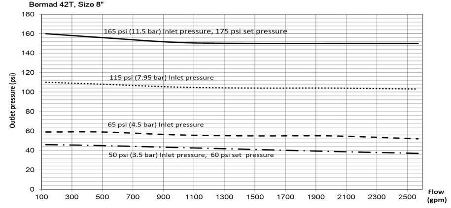
9 APPENDIX A: Fall Off Charts Bermad 42T Pressure Reducing Valve Outlet Pressure Verses Flow, Should inlet pressure falls below the valve outlet set pressure: Bermad 42T, Size 1.5, 2 and 2.5" Page 9 of 12


10 Page 10 of 12 IOM
11 Bermad 42T, Size 12" IOM Bermad 42T, Size 14" Bermad 42T, Size 16" Page 11 of 12
12 Page 12 of 12 IOM
Model: 720-UL INSTALLATION OPERATION MAINTENANCE. Bermad Pressure Reducing Valve IOM. Model: FP -720-UL Sizes: 2"-12" BERMAD. Application Engineering
 Bermad Pressure Reducing Valve Model: 720-UL INSTALLATION OPERATION MAINTENANCE Application Engineering BERMAD 1. Safety First BERMAD believes that the safety of personnel working with and around our equipment
Model: 43T. Bermad Pressure Relief Valve
 Model: 43T Bermad Pressure Relief Valve Installation Operation Maintenance Manual () Rev.C1_01.08.17 Page 1 of 10 Safety First BERMAD believes that the safety of personnel working with and around our equipment
I T T Pressure Reducing Valve WARNING INSTALLATION, OPERATION, AND MAINTENANCE MANUAL
 INSTALLATION, OPERATION, AND MAINTENANCE MANUAL I-867-4T 867-4T Pressure Reducing Valve HANG THESE INSTRUCTIONS ON THE INSTALLED VALVE FOR FUTURE REFERENCE WARNING Read and understand all instructions
Model 420-HY Pressure Regulating Hydrant Valve
 Model 420-HY Pressure Regulating Hydrant Valve INSTALLATION OPERATION MAINTENANCE 1. Safety First BERMAD believes that the safety of personnel working with and around our equipment is the most important
Installation Operation Maintenance. Bermad Level Control Valve with Modulating Horizontal Float Pilot valve One Way Flow IOM.
 Bermad Level Control Valve with Modulating Horizontal Float Pilot valve One Way Flow Model: FP 450-80 Installation Operation Maintenance PAGE 1 OF 5 1. Safety First BERMAD believes that the safety of personnel
WW-730. Pressure Sustaining/Relief Control Valve
 WW-730 Pressure Sustaining/Relief Control Valve Installation Operation & Maintenance Page 1 of 6 1. DESCRIPTION The Model 730 Pressure Relief / Sustaining Valve is an automatic control valve designed to
Bermad Model:
 Bermad Model: 405-02 Manually Operated Hydraulic Valve INSTALLATION OPERATION MAINTENANCE Application Engineering BERMAD 1. Safety First BERMAD believes that the safety of personnel working with and around
WW-720. Pressure Reducing Control Valve
 WW-720 Pressure Reducing Control Valve (Size Ranges: 2-4 and 6-14 ) Installation Operation & Maintenance Page 1 of 6 1. DESCRIPTION The Model 720 Pressure Reducing is an automatic control valve (powered
WW-720. Pressure Reducing Control Valve
 WW-720 Pressure Reducing Control Valve (Size Ranges: 2-4 and 6-14 ) Installation Operation & Maintenance Page 1 of 6 1. DESCRIPTION The Model 720 Pressure Reducing is an automatic control valve (powered
INSTALLATION OPERATION MAINTENANCE
 Bermad Electrically Controlled On-Off Deluge Valve Model: 400E-3D INSTALLATION OPERATION MAINTENANCE Application Engineering BERMAD 1. Safety First BERMAD believes that the safety of personnel working
TECHNICAL DATA Q= C. Table 1 - Specifications
 September 25, 2013 Pressure Regulation 537a 1. Description The Model B-3 Pilot Operated Pressure Control Valve is a factory assembled unit. The unit consists of a Model J-2 Halar coated Flow Control Valve,
TECHNICAL DATA. the Viking Pilot Pressure Regulating Valve 1 Model A-1 Speed Control Assembly: OBSOLETE. the Viking Speed Control Assembly 1
 November 30, 1994 534 a 1. PRODUCT NAME VIKING 2" (50mm), 3" (75mm), 4" (100mm), 6" (150mm) 2. MANUFACTURER THE VIKING CORPORATION 210 N. Industrial Park Road Hastings, Michigan 49058 U.S.A. Telephone:
TECHNICAL DATA. Table 1 - Specifications
 Page 1 of 6 1. DESCRIPTION Model A-3 Pilot Operated Pressure Control Valves are factory assembled units. Each unit consists of a Model H-2 Halar coated Flow Control Valve, a Speed Control Valve, a Model
Operation & Maintenance Manual Place this manual with valve or person responsible for maintenance of the valve
 Operation & Maintenance Manual Place this manual with valve or person responsible for maintenance of the valve Model CYCLE GARD II, CI & CNA YOUR PRODUCT INFORMATION: Model Number: Date: Serial Number:
TECHNICAL DATA. Q = C v P S
 Page 1 of 13 1. DESCRIPTION The Viking 6 Model G-6000 Dry Valve Riser Assembly consists of a small profile, light weight, pilot operated valve that is used to separate the water supply from the dry sprinkler
Pressure Reducing Control Valve w/ Hydraulic Check Feature
 PERTIN INSTRUTINS peration The BEE Model PR- Pressure Reducing ontrol alve with Hydraulic heck eature is a pilot controlled diaphragm valve designed to reduce a fluctuating higher upstream pressure to
Differential Pressure Regulator Type Type 45-6 (0.1 to 1 bar, DN 15) Mounting and Operating Instructions EB 3226 EN
 Mounting and Operating Instructions EB 3226 EN") Differential Pressure Regulator Type 45-6 Type 45-6 (0.1 to 1 bar, DN 15) Mounting and Operating Instructions EB 3226 EN Edition March 2008 Contents Contents Page 1 Design and principle of operation...................
Differential Pressure Regulator Type 45-6 Type 45-6 (0.1 to 1 bar, DN 15) Mounting and Operating Instructions EB 3226 EN Edition March 2008 Contents Contents Page 1 Design and principle of operation...................
TECHNICAL DATA. Q= Cv S
 Page 1 of 13 1. DESCRIPTION The Viking 4 inch Model G-4000 Dry Valve Riser Assembly consists of a small profile, light weight, pilot operated valve that is used to separate the water supply from the dry
TECHNICAL DATA. Page 1 of 12
 Page 1 of 12 1. DESCRIPTION The Viking Regulating Valve is a direct-acting, single-seated, spring-loaded diaphragm valve. When installed as a pilot regulating valve on a Viking Model H or J Flow Control
TECHNICAL DATA CAUTION
 Page 1 of 6 1. DESCRIPTION The Viking Model D-2 Accelerator is a quick-opening device, with an integral anti-flood assembly, used to increase the operating speed of a differential type dry pipe valve.
DS06D,G Dial Set Pressure Regulating Valve
 DS06D,G Dial Set Pressure Regulating Valve PRODUCT DATA FEATURES APPLICATION Built-in, factory-calibrated outlet pressure adjustment dial. Noncorroding unitized cartridge contains all working parts and
TECHNICAL DATA. Pressure Regulation 531a. April 24, 2009
 April 24, 29 Pressure Regulation 531a 1. DESCRIPTION The Viking Regulating Valve is a direct-acting, single-seated, spring-loaded diaphragm valve. When installed as a pilot regulating valve on a Viking
TECHNICAL DATA 3 MODEL G-3000 DRY VALVE RISER ASSEMBLY
 Page 1 of 13 1. DESCRIPTION The Viking 3 Model G-3000 Dry Valve Riser Assembly is equipped with a small profile, light weight, pilot operated valve that is used to separate the water supply from the dry
Discontinued. Powers Controls. Technical Instructions Document No P25 RV Rev. 1, May, RV 201 Pressure Reducing Valves.
 Powers Controls RV 201 Pressure Reducing Valves Description Features Product Numbers Dual Pressure PRV Technical Instructions Document No. 155-049P25 RV 201-1 Single Pressure PRV The RV 201 Pressure Reducing
End Connection. Thread x Thread N/A N/A N/A N/A Flange x Flange N/A
 Worldwide Contacts www.tyco-fire.com Model RV-1 Pressure Relief Valve, Pilot-Operated, Globe and Angle Body Styles General Description Valves, through inch (DN50 through DN00), are factory assembled and
TECHNICAL DATA Q = C. v P S. 2 Model G-2000 Dry valve. Page 1 of 13
 Page 1 of 13 1. Description The Viking 2 Model G-2000 Dry Valve Riser Assembly consists of a small profile, light weight, pilot operated valve that is used to separate the water supply from the dry sprinkler
TECHNICAL DATA. Inlet Type Outlet Type OBSOLETE. 4. TECHNICAL DATA Approvals:
 February 11, 2005 Deluge Valves 218 a 1. PRODUCT NAME Viking Model F-1 Deluge Valve 8" - Manufactured since 2002 4" & 6" - Manufactured since 2003 2-1/2" & 3" - Manufactured since 2004 2. MANUFACTURER
CAST IRON VALVES FLOAT VALVE
 CAST IRON VALVES FLOAT VALVE NETAFIM CAST IRON VALVES FLOAT VALVE INLINE 25-400MM ANGLE 50-100MM SPECIFICATIONS Manufactured to ISO 9001 Available Valve sizes INLINE Flanged 50mm to 600mm & Threaded 19mm
RS(H)10,15 USER MANUAL. Read the complete manual before installing and using the regulator.
10,15 USER MANUAL. Read the complete manual before installing and using the regulator.") RS(H)10,15 USER MANUAL Read the complete manual before installing and using the regulator. WARNING INCORRECT OR IMPROPER USE OF THIS PRODUCT CAN CAUSE SERIOUS PERSONAL INJURY AND PROPERTY DAMAGE. Due to
RS(H)10,15 USER MANUAL Read the complete manual before installing and using the regulator. WARNING INCORRECT OR IMPROPER USE OF THIS PRODUCT CAN CAUSE SERIOUS PERSONAL INJURY AND PROPERTY DAMAGE. Due to
Pressure Reducing Valve for Steam Type 2333 A
 Pressure Reducing Valve for Steam Type 2333 A Fig. 1 Type 2333 A 1. Design and principle of operation The pressure reducing valve consists of a balanced control valve and a closing actuator equipped with
TECHNICAL DATA DELUGE VALVE, MODEL F-1 STRAIGHT THROUGH STYLE
 Page 1 of 10 1. DESCRIPTION The Viking Model F-1 Deluge Valve is a quick opening, differential diaphragm and flood valve with one moving mechanism. The Deluge Valve is used to control water flow in Deluge
TECHNICAL DATA CAUTION
 Page 1 of 12 1. DESCRIPTION The Viking Model C-2 Pilot Pressure Regulating Valve is a direct-acting, single-seated, spring-loaded diaphragm valve. When installed as a pilot regulating valve on a Viking
D05 Pressure Regulating Valves
 D05 Pressure Regulating Valves FEATURES PRODUCT DATA Noncorroding unitized cartridge contains all working parts and is easily replaceable. Includes built-in strainer and thermal bypass. Balanced seat construction
DS05C,D,G Dial Set Pressure Regulating Valves
 DS05C,D,G Dial Set Pressure Regulating Valves APPLICATION The Honeywell DS05C,D,G Dial Set Pressure Regulating Valve is a high quality pressure regulating valve that maintains a constant outlet pressure
Combination Air Valve
 Combination Air Valve For Sewage and Wastewater Model C50 Installation, Operation and Maintenance Manual (IOM) Table of Contents General... Page 2 Safety... Page 2 Operational Data... Page 3 Materials
TECHNICAL DATA. Page 1 of 8. model f /2 (dn40) & 2 (dn50)
 & 2 (dn50)") Page 1 of 8 1. DESCRIPTION The Viking Model F-1 Deluge Valve is a quick opening, differential diaphragm, flood valve with one moving mechanism. The Deluge Valve is used to control water flow in Deluge
Page 1 of 8 1. DESCRIPTION The Viking Model F-1 Deluge Valve is a quick opening, differential diaphragm, flood valve with one moving mechanism. The Deluge Valve is used to control water flow in Deluge
Model GP PRESSURE REDUCING VALVE Installation & Operation Manual
 Model GP-2000 PRESSURE REDUCING VALVE Installation & Operation Manual Please read this bulletin thoroughly before using the pressure reducing valve, so that you may do so correctly and safely. Please carefully
PRS(TC)4,8 USER MANUAL. Read the complete manual before installing and using the regulator.
4,8 USER MANUAL. Read the complete manual before installing and using the regulator.") PRS(TC)4,8 USER MANUAL Read the complete manual before installing and using the regulator. WARNING INCORRECT OR IMPROPER USE OF THIS PRODUCT CAN CAUSE SERIOUS PERSONAL INJURY AND PROPERTY DAMAGE. Due to
PRS(TC)4,8 USER MANUAL Read the complete manual before installing and using the regulator. WARNING INCORRECT OR IMPROPER USE OF THIS PRODUCT CAN CAUSE SERIOUS PERSONAL INJURY AND PROPERTY DAMAGE. Due to
Anti-flood device Model B-1
 December 4, 2009 Dry Systems 123a 1. DESCRIPTION The Anti-flood Device is required when Viking accelerators are installed on dry systems according to Viking Model E-1 Accelerator Trim Charts. In the SET
Discharge Relief Valve Operation & Maint.
 Relief Valve Operation & Maint. CZ Series Centrifugal Fire Relief svalve Operation and Maintenance Instructions 1410 Operation and Maintenance Form No. F-1031 Section 2302.6 2111 Issue Date 04/90 11/95
Rate of Flow Valve Series 120
 SPECIFICATIONS Rate of Flow Valve Series DIMENSIONS The OCV Series 120 Rate of Flow control valve is designed to control or limit flow to a predetermined rate, regardless offl uctuations in downstream
SUBMITTAL NOTES PROJECT: Ross Model 50RWR-A Pilot Operated Surge Relief Valve with Hydraulic Anticipation. Size: inch / mm
 SUBMITTAL NOTES PROJECT: Ross Model 50RWR-A Pilot Operated Surge Relief Valve with Hydraulic Anticipation Size: inch / mm Every Ross Valve shall be hydrostatically tested for body integrity and tight seating
D05T Compact Design Pressure Regulating Valves
 D05T Compact Design Pressure Regulating Valves FEATURES PRODUCT DATA Non-corroding unitized cartridge contains all working parts and is easily replaceable. Includes built-in strainer and thermal bypass.
V43 Pressure Actuated Water Regulating Valve
 FANs 125, 121 Product/Technical Bulletin V43 Issue Date 0996 V43 Pressure Actuated Water Regulating Valve The V43 Pressure Actuated Water Regulating Valves are designed to regulate water flow for water-cooled
TECHNICAL DATA ANTI-FLOOD DEVICE MODEL B-1 1. DESCRIPTION
 Page 1 of 6 1. DESCRIPTION The Model B-1 Anti-flood Device is required when Viking accelerators are installed on dry systems according to Viking Model E-1 Accelerator Trim Charts. In the SET condition,
Type S301 & S302 Gas Regulators INTRODUCTION INSTALLATION. Scope of Manual. Description. Specifications. Type S301 and S302. Instruction Manual
 Fisher Controls Instruction Manual Type S301 & S302 Gas Regulators October 1981 Form 5180 WARNING Fisher regulators must be installed, operated, and maintained in accordance with federal, state, and local
TECHNICAL DATA PILOT PRESSURE REGULATED DELUGE SYSTEM CONTROLLED BY PNEUMATIC RELEASE. 1. DESCRIPTION (Refer to Figures 1, 2 or 3.
 Page 1 of 8 1. DESCRIPTION A Viking Pilot Pressure Regulated Deluge System utilizes a Viking Flow Control Valve to control water flow into the deluge system. The flow control valve must be installed with
1800C and 1800C-HC Series Service Regulators
 1800C and 1800C-HC Series Service Regulators Installation Instructions www.elster-americanmeter.com General Information: The 1800C and 1800C-HC Regulators are available as Full Capacity Internal Relief
Model GPR Primary Pressure Regulating Valve. Instruction Manual
 Model GPR-2000 Primary Pressure Regulating Valve Instruction Manual Please read this instruction manual thoroughly before using the primary pressure regulating valve, so that you may do so correctly and
BACK PRESSURE / SUSTAINING
 In many liquid piping systems, it is vital that line pressure is maintained within relatively narrow limits. This is the function of the 108 Pressure Relief / Back Pressure Series of the OCV control valves.
SINGER MODEL 106/206-RPS-L&H
 DESCRIPTION: Model 106/206-RPS-L&H dissipates surges caused by power failure to pumps. The valve anticipates the surge by opening on low line pressure associated with sudden stopping of pumps. This assures
BACK PRESSURE / SUSTAINING
 SPECIFICATIONS DIMENSIONS In many liquid piping systems, it is vital that line pressure is maintained within relatively narrow limits. This is the function of the 108 Pressure Relief / Back Pressure Series
Mounting and operating instructions EB 2530 EN. Self-operated Pressure Regulator. Pressure Reducing Valve Type M 44-2
 Self-operated Pressure Regulator Pressure Reducing Valve Type M 44-2 Type M 44-2, connection G 1 4, K VS = 0.15 Type M 44-2, connection G 1, K VS = 6 Fig. 1 Type M 44-2 Pressure Reducing Valve Mounting
Installation, Operation and Maintenance Manual for Back Pressure Regulator
 Installation, Operation and Maintenance Manual for Back Pressure Regulator Model 8860 2009 Groth Corporation IOM-8860 Rev. B 12541 Ref. ID: 95565 Page 2 of 13 Table of Contents I. INTRODUCTION 3 II. DESIGN
INSTALLATION INSTRUCTIONS. CVS 67CFR Pressure Reducing Instrument Supply Regulator INTRODUCTION
 INSTALLATION INSTRUCTIONS CVS 67CFR Pressure Reducing Instrument Supply Regulator INTRODUCTION The CVS Controls 67CFR Filter regulator is a pressure reducing supply regulator typically used for pneumatic
TECHNICAL DATA ACCELERATOR MODEL E-1
 Page 1 of 10 1. PRODUCT DESCRIPTION The Viking Model E-1 Accelerator is a quick-opening device. When installed with the required external Anti-flood Device, the assembly is designed to increase the operating
RHPS Series RD(H)F40 User Manual. Read the complete manual before installing and using the regulator.
F40 User Manual. Read the complete manual before installing and using the regulator.") RHPS Series RD(H)F40 User Manual Read the complete manual before installing and using the regulator. 2 WARNING Before removing a regulator from the system for service, you must depressurize system purge
RHPS Series RD(H)F40 User Manual Read the complete manual before installing and using the regulator. 2 WARNING Before removing a regulator from the system for service, you must depressurize system purge
TECHNICAL DATA. Deluge Valves 218a. November 30, 2007 DELUGE VALVE MODEL F-1 STRAIGHT THROUGH STYLE 2-1/2 (DN65) - 8 (DN200)
 - 8 (DN200)") November 30, 2007 Deluge Valves 218a DESCRIPTION The Viking Model F-1 Deluge Valve is a quick opening, differential diaphragm and fl ood valve with one moving mechanism. The Deluge Valve is used to control
November 30, 2007 Deluge Valves 218a DESCRIPTION The Viking Model F-1 Deluge Valve is a quick opening, differential diaphragm and fl ood valve with one moving mechanism. The Deluge Valve is used to control
Regulator from 1800 B series
 Regulator from 1800 B series Regulator from 1800 B series Measuring of industrial gases frequently requests a precise pressure regulation for the purpose of dosage and proccesing. UNIS FAGAS has two kinds
TECHNICAL DATA. Q = C v P S
 Preaction 346a 1. Description The 6 Model G-6000P Electric Release Preaction System Riser Assembly can be used as a Single Interlock Preaction System with Electric Release, or as a Double Interlock Preaction
BERMAD Waterworks. Level Control Valve with Altitude Pilot. 700 Series. Model X. Features and Benefits. Major Additional Features
 Level Control Valve with Altitude Pilot High level reservoirs & water towers Energy cost critical systems Systems with poor water quality Inherent refreshing Level sustaining at reservoir outlet The Level
DESIGN DATA A WET PIPE BLADDER TANK FOAM/WATER SYSTEM WITH HYDRAULICALLY ACTUATED DELUGE CONCENTRATE CONTROL VALVE
 February 9, 1998 Foam 101a A BLADDER TANK WITH 1. DESCRIPTION A Wet Pipe Bladder Tank Foam/Water System is a standard wet pipe automatic sprinkler system capable of discharging a foam/water solution automatically
for Building facilities Industrial facilities etc.,multipurpose Pilot operated type(high capacity)
") for Building facilities Industrial facilities etc.,multipurpose Pilot operated type(high capacity This is a Pilot operated pressure reducing valve. It is suitable to install in the steam lines with the
for Building facilities Industrial facilities etc.,multipurpose Pilot operated type(high capacity This is a Pilot operated pressure reducing valve. It is suitable to install in the steam lines with the
MEGR-1627 Instruction Manual
 MEGR-1627 HIGH FLOW GAS REGULATOR Instruction Manual- Look Inside For: Description Installation Remote Vent Line Installations Startup and Adjustment Shutdown Maintenance Body Maintenance Procedures Diaphragm
KTM 50 (DN ) Installation, maintenance and operating instructions
 Installation, maintenance and operating instructions") 52 762-306 09.2014 KTM 50 (DN 100-200) Installation, maintenance and operating instructions General High-performing and compact, these pressure-independent control valves for variable flow heating and
52 762-306 09.2014 KTM 50 (DN 100-200) Installation, maintenance and operating instructions General High-performing and compact, these pressure-independent control valves for variable flow heating and
RD(H)20/25 Pressure-Reducing Regulator User Manual
20/25 Pressure-Reducing Regulator User Manual") RD(H)20/25 Pressure-Reducing Regulator User Manual Read the complete manual before installing and using the regulator. 2 Safe Product Selection When selecting a product, the total system design must be
RD(H)20/25 Pressure-Reducing Regulator User Manual Read the complete manual before installing and using the regulator. 2 Safe Product Selection When selecting a product, the total system design must be
Anderson Greenwood Series 93 Positive Pressure POSRV Installation and Maintenance Instructions
 Before installation these instructions must be fully read and understood Installation and maintenance instructions for Series 93 Positive Pressure Pilot Operated Safety Relief Valves (POSRV). The intent
Models 106-RF / 206-RF Rate of Flow Control Valve
 Rate of Valve KEY FEATURES Accurately limits low to a pre-set maximum Easily adjustable low limit Paddle-style oriice plate included Optional oriice plate housing 106-RF Globe Product Overview The 106-RF
TECHNICAL DATA OBSOLETE
 April 9, 2009 Preaction 326a 1. DESCRIPTION Viking supervised Double-Interlocked Electric/Pneumatic Release Preaction Systems utilizing the Viking G-4000P Deluge Valve. The small profi le, lightweight,
FILTER BYPASS CONTROL
 Differential Control Valve Series 110 The Series 110 Differential Control Valve is designed to accurately control the pressure difference between any two points. In some systems this means the valve remains
Pressure Independent Control Series
 Document No. 155-522 Pressure Independent Control Series Two-Way Cast Iron Flanged Bodies, ANSI 125 and 250 Description Siemens Pressure Independent Control Valves integrate three functions into a single
299H Series. Introduction. P.E.D. Categories. Specifications. Installation. Warning. Installation Guide English September 2012
 Installation Guide English September 2012 299H Series Introduction This Installation Guide provides instructions for installation, startup, and adjustment of 299H Series regulators. To receive a copy of
HYDRAULIC CONTROL VALVES
 HYDRAULIC CONTROL VALVES INC. VALVES, INC HYDRAULIC CONTROL VALVES WORKING PRINCIPALS It is automatic hydraulic control valve designed for make desired modulation processes in main valve network line as
1200B2 Series Service Regulators. Instruction Manual
 00B Series Service Regulators Instruction Manual 00B Series Service Regulators 0 Elster American Meter 00B Series Service Regulators General Information The 00B Series Service Regulators are available
TECHNICAL DATA. Q = C v P S
 January 6, 2012 Preaction 331a 1. Description Viking supervised Double-Interlocked Electric/Pneumatic Release Preaction Systems utilize the Viking G-3000P Valve. The small profile, lightweight, pilot-operated
APPLYING VARIABLE SPEED PRESSURE LIMITING CONTROL DRIVER FIRE PUMPS. SEC Project No
 APPLYING VARIABLE SPEED PRESSURE LIMITING CONTROL DRIVER FIRE PUMPS SEC Project No. 1803007-000 November 20, 2006 TABLE OF CONTENTS I. ABSTRACT...1 II. INTRODUCTION...1 III. HISTORY...2 IV. VARIABLE SPEED
TECHNICAL DATA. Q = C v P S
 January 6, 2012 Preaction 333a 1. Description Viking supervised Surefire Preaction Systems Utilize the Viking G-3000P Valve. The small profile, lightweight, pilot-operated Viking G-3000P Valve comes complete
BERMAD Fire Protection Hydraulic Control Valves
 BERMAD Fire Protection Hydraulic Control Valves Control Solutions with the Power to Protect BERMAD - The Company Since its foundation in 1965, BERMAD has focused its efforts on innovation, quality and
Wet pipe low flow foam/water system
 December 6, 2010 Foam 14a 1. The Viking Low Flow Foam/Water proportioning system, is a UL Listed and FM Approved system, for use with Viking supplied foam concentrates. This system consists of a standard
TECHNICAL DATA. Q = C v P S
 January 6, 2012 Preaction 348a 1. Description Viking supervised Surefire Preaction Systems utilize the Viking G-6000P Valve. The small profile, lightweight, pilot operated Viking G-6000P Valve comes complete
DESIGN DATA OBSOLETE. C. Inspections - It is imperative that the system be inspected and tested on a regular basis. See Inspection
 February 9, 1998 Foam 201a 1. DESCRIPTION A Deluge Bladder Tank Foam/Water System is a standard deluge system capable of discharging a foam/water solution automatically through open sprinklers, spray nozzles,
Waterous Relief Valve
 Operating Instructions 1. Reduce pump discharge pressure with engine throttle. Make sure four way (On/Off) valve is OFF. 2. Open at least one discharge valve. Accelerate engine until pressure gage indicates
TECHNICAL DATA. Deluge Valves 211a. November 30, 2007 DELUGE VALVE MODEL E-1 ANGLE STYLE 3 (DN80), 4 (DN100) & 6 (DN150)
, 4 (DN100) & 6 (DN150)") November 30, 2007 Deluge Valves 211a DESCRIPTION The Viking Model E-1 Deluge Valve is a quick-opening, differential diaphragm, fl ood valve with one moving mechanism. The deluge valve is used to control
November 30, 2007 Deluge Valves 211a DESCRIPTION The Viking Model E-1 Deluge Valve is a quick-opening, differential diaphragm, fl ood valve with one moving mechanism. The deluge valve is used to control
Combination Air Valve Model
 Combination Air Valve Model Model C10 /C11 Installation, Operation and Maintenance Manual (IOM) Table of Contents General...Page 2 Safety...Page 2 Operational Data...Page 3 Materials and Connections...Page
TECHNICAL DATA PILOT PRESSURE REGULATED DELUGE SYSTEM CONTROLLED BY ELECTRIC RELEASE 1. DESCRIPTION 2. LISTINGS AND APPROVALS 3.
 Page 1 of 8 1. DESCRIPTION A Viking Pilot Pressure Regulated Deluge System utilizes a Viking flow control valve to control water flow into the deluge system. The flow control valve must be installed with
TECHNICAL DATA. Q = C v P S
 January 6, 2012 Preaction 347a 1. Description Viking supervised Double-Interlocked Electric/Pneumatic Release Preaction Systems utilize the Viking G-6000P Valve. The small profile, lightweight, pilot operated
LRS(H)4 USER MANUAL. Read the complete manual before installing and using the regulator.
4 USER MANUAL. Read the complete manual before installing and using the regulator.") LRS(H)4 USER MANUAL Read the complete manual before installing and using the regulator. WARNING INCORRECT OR IMPROPER USE OF THIS PRODUCT CAN CAUSE SERIOUS PERSONAL INJURY AND PROPERTY DAMAGE. Due to the
LRS(H)4 USER MANUAL Read the complete manual before installing and using the regulator. WARNING INCORRECT OR IMPROPER USE OF THIS PRODUCT CAN CAUSE SERIOUS PERSONAL INJURY AND PROPERTY DAMAGE. Due to the
SINGLE VALVE WITH LOW-FLOW BYPASS
 CONTROL VALVES Pressure Reducing Valve Sizing Guide Sizing pilot operated reducing valves is not a complicated process. It starts with determining requirements and following these guidelines in valve size
WHEATLEY WHEATLEY SERIES 500 SWING CHECK VALVE. Installation, Operation and Maintenance Manual
 WHEATLEY SERIES 500 SWING CHECK VALVE STANDARD INTEGRAL SEAT & OPTIONAL REMOVABLE SEAT 2" FP - 6" FP 150# - 1500# 8" FP - 12" FP 150# - 900# API 6D and B16.34 2" FP - 4" FP 5000# DRILLING PRODUCTION VALVE
TECHNICAL DATA. TRIMPAC Model B-5 & B-5B
 September 16, 2013 Trimpac 250a 1. DESCRIPTION DEsCRIPTIoN is a factory assembled trim package for a ed an electric/pneumatic release module in a metal enclosure. The standard trim normally required on
Assembly Drawing: W-311B-A01, or as applicable Parts List: W-311B-A01-1, or as applicable Special Tools: , , &
 REDQ Regulators Model 411B Barstock Design Powreactor Dome Regulator OPERATION AND MAINTENANCE Contents Scope..............................1 Installation..........................1 General Description....................1
LRS(H)4 Pressure-Reducing Regulator User Manual
4 Pressure-Reducing Regulator User Manual") LRS(H)4 Pressure-Reducing Regulator User Manual Read the complete manual before installing and using the regulator. 2 Safe Product Selection When selecting a product, the total system design must be considered
LRS(H)4 Pressure-Reducing Regulator User Manual Read the complete manual before installing and using the regulator. 2 Safe Product Selection When selecting a product, the total system design must be considered
TECHNICAL DATA. than the water inlet pressure to the concentrate
 Foam102a 1. DESCRIPTION The Viking Low Flow Foam/Water proportioning system, is a UL Listed and FM Approved system, for use with 3M foam concentrates. This system consists of a standard wet pipe sprinkler
Model 7989T Steel Pipe Squeezer Sch. 40 & Sch. 80. Operations Manual
 10-12 Steel Pipe Squeezer Sch. 40 & Sch. 80 Operations Manual 1.0 Introduction This manual is issued as a basic operation manual covering the Regent Model 7989T, Pipe Squeezer and Pump as manufactured
Mounting and Operating Instructions EB EN. Self-operated Pressure Regulators. Type 2335 Excess Pressure Valve with pilot valve
 Self-operated Pressure Regulators Type 2335 Excess Pressure Valve with pilot valve Type 2335 Excess Pressure Valve Mounting and Operating Instructions EB 2552-2 EN Edition January 2016 Definition of signal
Mounting and Operating Instructions EB 3007 EN. Self-operated Pressure Regulators. Type Type Differential Pressure Regulators (opening)
") Self-operated Pressure Regulators Type 42-20 Type 42-25 Differential Pressure Regulators (opening) Translation of original instructions Type 42-20 Differential Pressure Regulator Type 42-25 Differential
Self-operated Pressure Regulators Type 42-20 Type 42-25 Differential Pressure Regulators (opening) Translation of original instructions Type 42-20 Differential Pressure Regulator Type 42-25 Differential
THE HF-300 SERIES. Operating and Service Manual. Series includes all variants of HF-300/301
 THE HF-300 SERIES Operating and Service Manual Series includes all variants of HF-300/301 Issue A July 2015 1 TABLE OF CONTENTS 1. Description... 3 2. Installation... 3 3. Operation... 4 3.1. Spring Loaded...
Mounting and Operating Instructions EB 2555 EN. Self-operated Pressure Regulators. Pressure Reducing Valves Type 50 ES Type 50 EM.
 Self-operated Pressure Regulators Pressure Reducing Valves Type 50 ES Type 50 EM Type 50 ES Type 50 EM Fig. 1 Pressure reducing valves Mounting and Operating Instructions EB 2555 EN Edition November 2011
VALVES HIDROMATIC VALVE.
 VALVES HIDROMATIC VALVE Hydrodynamic design The Hidromatic valve of Hidroconta is a piston hydraulic valve controlled with the same fluid of the conduction. Its balloon design improves its hydrodynamic
Mounting and Operating Instructions EB 3007 EN. Self-operated Pressure Regulators. Differential Pressure Regulators (opening) Type Type 42-25
 Type Type 42-25") Self-operated Pressure Regulators Differential Pressure Regulators (opening) Type 42-20 Type 42-25 Type 42-20 Differential Pressure Regulator Type 42-25 Differential Pressure Regulator Mounting and Operating
Self-operated Pressure Regulators Differential Pressure Regulators (opening) Type 42-20 Type 42-25 Type 42-20 Differential Pressure Regulator Type 42-25 Differential Pressure Regulator Mounting and Operating