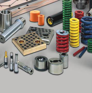
PINS & BUSHINGS METRIC
|
|
|
- Cody Sims
- 5 years ago
- Views:
Transcription


1 PINS & BUSHINGS METRIC
2 PINS & BUSHINGS METRIC CONTENTS PAGE NUMBER General Information 1 Plain & Ball Bearing Guide Posts Press Fit Guide Posts 2 Demountable Guide Posts 4 Automotive Straight Guide Posts 6 Plain Bearing & Self-Lubricating Bushings Automotive Demountable Self-Lubricating Guide Post Bushings 8 Automotive Demountable Self-Lubricating PAD Bushings 9 Automotive Demountable Self-Lubricating Bushings Clamps 10 Lifter Pins 13 Demountable Plain Bearing Bushings (Extra Long, Standard and Short Shoulder Series) 14 Demountable Plain Bearing Low Profi le Bushings 16 Self-Lubricating Ejector Bushings 17 Ball Bearing Components Ball Bearing Cages 18 Ball Bearing Demountable Bushings 19 Ball Bearing Straight Sleeve Bushings 20 Demountable Ball Bearing Stripper Bushings & Cages 21 Technical Information Mounting Accessories 22 Ball Bearing Selection Guide 23 Bore Size Data 30 Clamping Specifi cations for Demountable Post & Bushings 32 Miscellaneous Cage Stopper End Caps 34 Pad Retainers Standard Mount Metric 35 Pad Retainers Reverse Mount Metric 36


3 General Information As the premier die set manufacturer, we offer a co mplete line of catalog die sets as well as custom complex and simple sets. For replacement parts and for those customers wanting to assemble their own sets, an extensive line of catalog guide posts and bushings in both plain bearing and ball bearing styles is available for iediate delivery. Our guide posts are available in press fi t and demountable styles. Both the -82 and -83 posts can be used in a plain bearing or a ball bearing system. The NP line of guide posts fully meet NAAMS standards. Our plain bearing bushings are available in press fit and demountable styles and are equipped with fi gure 8 oil grooves and lubrication fi ttings. They are available in three profi les: standard, short and extra long shoulder to give optimum flexibility in die set design. The bushings are also available in steel, bronze-plated and self-lubricating materials and are ideally suited for running with metric posts. Demountable posts and bushings are tap fi t into location and seat fl ush with the ground face of the punch holder or die shoe. They are held in place with toe clamps and screws which provide perfect alignment of the post and bushing with the bore perpendicular to the ground surface of the punch holder or shoe. The clamp and screws provide four times the holding power compared to pressed-in components, yet they can be easily removed and assembled thus simplifying die building and maintenance. The ball bearing system includes press fi t and demountable guide posts, press fi t sleeves and demountable bushings as well as ball cages. The ball bearing guide posts are manufactured from hardened steel to assure free rolling of balls and high wear resistance. Each post is drilled and tapped at the bottom for mounting of the ball cage washer assembly. This unique mounting method permits the ball cage, except when under pre-load, to freely rotate 360 around the guide post thus eliminating scoring or tracking of the guide post surface. The ball bearings are arranged in the cage in a spiral pattern which also minimizes tracking or grooving and assures uniform wear. Our demountable bushings and guide posts provide ease of assembly. Demountable bushings are secured to the punch holder with clamps and screws, proving four times the holding power of pressed-in bushings. Specially-designed spiral patterns are drilled into our ball cages to control tracking and grooving. Special equipment spins ball bearings in place, then our ball cages move on to rigid quality inspection. 1
4 Plain & Ball Bearing Press Fit Guide Posts Product Features These press fi t guide posts are designed to run in both a plain and ball bearing systems. They are manufactured from high quality hardened steel and fi nish ground for a high precision fi nish. The diameters that are used in ball bearing applications are drilled and tapped on the working end for the mounting of the ball cage washer assembly. This unique mounting method permits the ball cage, except when under preload, to freely rotate 360 degrees around the guide post, thus eliminating scoring or tracking of the guide post surface. NOTES: Press fi t length should be equal to or greater than the diameter of the guide post. See pages for die set boring specifi cations. Ball Cage washer assembly sold separately and dependent on Type I, II or III assembly methods. Refer to page 22 for washer assembly part numbers. The diameters that are used in ball bearing applications are drilled and tapped on the working end for the mounting of the ball cage washer assembly. D L 100 U
5 Plain & Ball Bearing Press Fit Guide Posts D L U D L U D L U M M M M M M

6 Plain & Ball Bearing Demountable Guide Posts Product Features These demountable guide posts are designed to run in both plain and ball bearing systems. They are manufactured from high quality hardened steel and fi nish ground for a high precision fi nish. The diameters that are used in ball bearing applications are drilled and tapped on the working end for the mounting of the ball cage washer assembly. This unique mounting method permits the ball cage, except when under preload, to freely rotate 360 degrees around the guide post, thus eliminating scoring or tracking of the guide post surface. There are two ways of mounting the demountable posts into the die set: they can be either held in place with toe clamps and screws or they can be mounted using a retainer plug. Either mounting option offers the benefi t of easy removal, even multiple times without damaging or distorting the mounting holes in the die set, thus simplifying die building and maintenance. Demountable posts are also used to replace press fi t posts when the press fit hole has been damaged and the straight pin no longer fi ts securely in the hole. NOTES: All demountable guide posts are supplied with mounting clamps and screws. See pages for clamping dimensions or to order additional toe clamps or mounting screws. Ball Cage washer assembly sold separately and dependent on Type 1, 2 or 3 assembly methods. Refer to page 22 for washer assembly part numbers. D D5 E1 Tap Size L Tap Size U M M M M6 M M M6 M M M10 M M M12 M M16 M M16 M10 Retainer plugs must be ordered separately. Refer to page 32 for part numbers and dimensional information. The diameters that are used in ball bearing applications are drilled and tapped on the working end for the mounting of the ball cage washer assembly. 4
7 Plain & Ball Bearing Demountable Guide Posts D F1 D F1 D F

8 Automotive Straight Guide Posts NPH Product Features NAAMS guide posts are manufactured in accordance with the North American Automotive Metric Standards. They are manufactured from high quality hardened steel and finish ground for a high precision finish. Hardness is RC with a minimum depth of 0.8 min. These posts are ideally suited for the self-lubricating NAAMS bushings. To reduce tooling weight, the 100 and 125 diameter posts, NPH series, are manufactured with a through hole. For NP Series (Solid Posts) For NPH Series (Hollow Posts) NAAMS Code GM Chrysler Ford NP25-80 G NP G NP NP G NP G WDX NP G WDX NP G WDX NP G NP G NP NP G WDX NP G WDX NP G WDX NP G WDX NP NP G WDX NP G WDX NP G WDX NP G WDX NP G WDX NP NP G WDX NP G WDX NP G WDX NP G WDX NP G WDX NP G WDX NP G WDX NP D1 & D2 D2 Tol r6 D3 L L2 L3 R Pressed Fit Bore
9 Automotive Straight Guide Posts NAAMS Code GM Chrysler Ford NP NP G WDX NP G WDX NP G WDX NP G WDX NP G WDX NP G WDX NP G WDX NP NP G NP NP G WDX NP G WDX NP G WDX NP G WDX NP G WDX NP WDX NP G WDX NP A 250 NP A 280 NP G WDX NP G WDX NP G WDX NP A NP G A WDX NP A WDX NP A WDX NP A 650 NPH B 315 NPH B 355 NPH B NPH B* NPH B NPH B* 550 NPH B* 600 NP G NP G NP A 315 NP A 355 NP G A 400 NP G A NP G A NP G A NP G A 600 NP G A 650 NP G A 700 NPH B 315 NPH B* WDX ** 355 NPH B WDX ** 400 NPH B WDX ** NPH B WDX ** NPH B WDX ** 550 NPH B WDX ** 600 NPH B WDX ** 650 D1 & D2 D2 Tol r6 D3 L L2 L3 R Pressed Fit Bore * Not for North American Operations use. ** Non-standard parts. s must be ordered as shown. 7

10 Automotive Demountable Self-Lubricating Guide Post Bushings NM25 Product Features Demountable NAAMS bushings are self-lubricating and are available in guide post and pad styles. These bushings fully conform to the NAAMS, GM, Chrysler and Ford standards. Self-lubricating bushings contain graphite plugs which are impregnated with oil. When the bushings reach F as a result of friction between the bushing and guide post, oil is drawn from the plug, thus lubricating the wear surface. A dark smear pattern is created on the wear surface as the oil and graphite are imbedded into the bronze or steel grain. This provides the lubrication necessary for continuous performance of the tool. Demountable bushings are tap fit into location and seat flush with the ground face of the punch holder. The bushings are held in place with toe clamps and screws which provide perfect alignment of the bushing with the bore perpendicular to the ground surface of the punch holder. Multipe standard clamps are available. D1 D2 D3 D4 L1 L2 L3 R NAAMS Bushing GM Chrysler Ford NM25 G WDX NM32 G WDX NM40 G WDX NM50 G WDX NM63 G WDX NM80 G WDX NM100 G WDX NM100S S NM115 G NM125 G WDX CLAMP NOTES: See pages for clamp part numbers and dimensional information. OUR bushings will be supplied with (3) M8 toe clamps and screws (#6-99-1). NAAMS bushings will be supplied with (3) M8 toe clamps and screws (#6-99-1). GM bushings are supplied with NO clamps and screws. Order separately: for 25-50, order (1) A clamp per bushing; for , order (2) B clamps per bushing. CHRYSLER guide post bushings are supplied with NO clamps or screws. Order STOP/BUSHING CLAMP COMBINATION BLOCK separately. See Table 1 for sizes and part numbers. Ford bushings: are supplied with (1) toe clamp (#MMC0219); are supplied with (2) toe clamps (#MMC0219). TABLE 1 STOP BLOCK/BUSHING CLAMPS Chrysler Bushing ID

11 Automotive Demountable Self-Lubricating PAD Bushings NM25PAD D1 D2 D3 L1 L2 NAAMS Code GM Chrysler Ford NM25PAD G WDX NM32PAD G WDX NM40PAD G WDX NM50PAD G * WDX NM63PAD G * WDX NM63-125PAD * NM80PAD G * WDX NM80-140PAD * NM100PAD G WDX NM PAD NM125PAD G CLAMP NOTES: See pages for clamp part numbers and dimensional information. OUR PAD bushings will be supplied with (3) M8 toe clamps and screws (#6-99-1). NAAMS PAD bushings will be supplied with (3) M8 toe clamps and screws (#6-99-1). GM PAD bushings are supplied with NO clamps and screws. Order separately; for 25-50, order (1) A clamp per bushing; for , order (2) B clamps per bushing. CHRYSLER PAD bushings are supplied with (3) M10 toe clamps and screws ( ). Chrysler PAD bushings with * DO NOT come with M10 clamps and screws (10/15/07 Die Standards). They use the PAD Bushing Retainer Block shown in Table 2 and must be ordered separately. Ford PAD bushings: are supplied with (1) toe clamp (#MMC0219); are supplied with (2) toe clamps (#MMC0219). TABLE 2 PAD BUSHING RETAINER BLOCK CLAMPS Chrysler Pad Bushing ID RECOMENDED BORE SIZES FOR NAAMS GUIDE POST BUSHINGS AND PAD BUSHINGS D1 Wring Fit Bore / / / / / / / / /
12 Automotive Demountable Self-Lubricating Bushing Clamps CLAMP SPECIFICATIONS DANLY / IEM / NAAMS / CHRYSLER NAAMS Chrysler A B C D G720000C N/A M8 x G730000C M10 x 1.5 NOTE: D1 = ID of bushing D3 = OD of bushing shoulder PART # (NAAMS #G720000C) D1 D3 BC N PART # (NAAMS #G730000C) D1 D3 BC N CLAMP SPECIFICATIONS GM GM A B Bushing I.D C D E F G H J K Clamps Required NOTE: Clamps are to be ordered with each bushing. 10
13 Automotive Demountable Self-Lubricating Bushing Clamps CLAMP SPECIFICATIONS CHRYSLER STOP/BUSHING CLAMP COMBINATION BLOCK D1 D2 Chrysler Bushing Code I.D CLAMP SPECIFICATIONS CHRYSLER PAD BUSHING RETAINER BLOCK TOP VIEW Chrysler Bushing I.D. A B C D E * * * * For bottoming of pads/lower rings. SIDE VIEW 11
14 Automotive Demountable Self-Lubricating Bushing Clamps CLAMP SPECIFICATIONS FORD TOE CLAMPS 25 PART NUMBER MMC-0217 Ford Bushing L1 L2 L3 L4 L5 L6 L7 L8 D1 D2 Size WDX NOTE: For FORD 25 bushing only CLAMP SPECIFICATIONS FORD TOE CLAMPS PART NUMBER MMC-0219 Ford Bushing L1 L2 L3 L4 L5 L6 L7 L8 D1 D2 Size WDX NOTE: For FORD bushings only 12

15 Lifter Pins Product Features Lifter pins are manufactured from 1144 steel and are coonly used to handle large die sets. They conform to NAAMS standards. The internal spring provides added assurance that the fall ring will function properly during the course of the pin s use. LP NAAMS + 0 A -.03 B C D E F Total Die Wt. in Code Metric Tons (t) LP L LP L LP L LP L

16 Demountable Plain Bearing Bushings & Product Features Demountable bushings are available in three profi les: extra long, long, and short shoulder to give optimum fl exibility in die set design. The bushings are manufactured from hardened steel and are ideally suited for running with press fi t or demountable posts. The bronzeplated bushings offer superior resistance to seizure, the major cause of bushing wear. They are recoended in high speed applications and where high side thrust loads are present. Demountable bushings are tap fi t into location and seat fl ush with the ground face of the punch holder. The bushings are held in place with toe clamps and screws which provide perfect alignment of the bushing with the bore perpendicular to the ground surface of the punch holder. The clamp and screws provide four times the holding power compared to pressed-in bushings, yet they can be easily removed and assembled thus simplifying die building and maintenance. All bushings are equipped with figure 8 oil grooves and lubrication fi ttings. EXTRA LONG SHOULDER Steel Bronze D1 D2 D3 D4 E F L Plated NOTES: All demountable bushings are supplied with mounting clamps and screws. See page for clamping dimensions or to order additional toe clamps or mounting screws. Bronze-plated bushings should not be pressed-in or honed. See pages for die set boring specifi cations. 14


17 Demountable Plain Bearing Bushings & LONG SHOULDER Steel Bronze D1 D2 D3 D4 E F L Plated & SHORT SHOULDER Steel Bronze D1 D2 D3 D4 E F L Plated

18 Demountable Plain Bearing Low Profile Bushings Product Features Low profi le demountable bushings are designed so that the main body of the bushing is contained within the punch holder while only a minimum of the bushing projects below the punch holder and into the die area. With minimal bushing projection, this model is ideal for dies running in presses with automatic transfer devices. Since the bushings do not need to be removed during grinding, it is well suited for applications that require often die sharpening. The bronze-plated bushings offer superior resistance to seizure, the major cause of bushing wear. They are recoended in high speed applications and where high side thrust loads are present. Demountable bushings are tap fi t into location and seat fl ush with the ground face of the punch holder. The bushings are held in place with toe clamps and screws which provide perfect alignment of the bushing with the bore perpendicular to the ground surface of the punch holder. The clamp and screws provide four times the holding power compared to pressed-in bushings, yet they can be easily removed and assembled, thus simplifying die building and maintenance. NOTES: All demountable bushings are supplied with mounting clamps and screws. See pages for clamping dimensions or to order additional toe clamps or mounting screws. Bronze-plated bushings should not be pressed-in or honed. See pages for die set boring specifi cations. D1 D2 D3 D4 E F L Hole Location G Steel Bronze- Plated


19 Self-Lubricating Ejector Bushings Product Features These self-lubricating bushings contain graphite plugs which are impregnated with oil. When the bushing reach F as a result of friction between the bushing and guide post, oil is drawn from the plug, thus lubricating the wear surface. A dark smear pattern is created on the wear surface as the oil and graphite are imbedded into the bronze or steel grain. This provides the lubrication necessary for continuous performance of the tool. MME25 NOTES: See pages for die set boring specifi cations. 5 D A B C L1 L MME MME MME30 17


20 Ball Bearing Cages Product Features Ball cages are manufactured from a heat treated aluminum alloy which provides tough, wear resistant qualities. The ball bearings are vacuum degassed quality, fatigue resistant steel and are inspected to ensure roundness, smoothness and dimensional conformance. The ball bearings are arranged in the cage in a spiral pattern to minimize tracking or grooving and assure uniform wear. Ball cages are mounted to drilled and tapped guide posts by a special washer assembly which permits the cage to rotate freely around the guide post when not under preload. TYPE I For Type I Ball Bearing Bushing Assembly TYPE II For Type II and Type III Ball Bearing Bushing Assemblies D C S X Type I Type II D C S X Type I Type II

21 Ball Bearing Demountable Bushings Product Features Demountable bushings are tap fit into location and seat flush with the ground face of the punch holder. The bushings are held in place with toe clamps and screws which provide perfect alignment of the bushing with the bore perpendicular to the ground surface of the punch holder. The clamp and screws provide four times the holding power compared to pressed-in bushings, yet they can be easily removed and assembled thus simplifying die building and maintenance D D1 D2 D3 D4 E F L NOTES: All demountable bushings are supplied with mounting clamps and screws. See pages for clamping dimensions or to order additional toe clamps or mounting screws. See pages for die set boring specifi cations. 19

22 Ball Bearing Straight Sleeve Bushings Product Features Press fit bushings are manufactured from high quality hardened steel, the bushings are finish ground for a press fit. Like all ball bearing components, these straight sleeve bushings are completely interchangeable INSTALLATION INSTRUCTIONS In order to avoid the bushing close-in which occurs as a result of pressfi t, these bushings should be retained with a Bushing Mount. When so installed, it is not necessary to hone the bushing bore after installation, and the bushing fi t will be correct. APPLICATION OF THE BUSHING MOUNT 1. Degrease bushing OD and die shoe bore with alcohol, acetone or other volatile solvent and wipe dry. 2. Apply Bushing Mount sparingly and wring bushing into die shoe. 3. Allow a 4-hour cure at 72 F (23 C). Do not disturb bushing until cure is complete. Bushing Mount number: Post Diameter D1 D2 L2 Post Diameter D1 D2 L

23 Demountable Ball Bearing Stripper Bushings and Cages Product Features Type III cages are made using the same material and control standards as our Type I & II cages. Type III cages use an external snap ring to act as a cage carrier and stop. This allows the cage to rotate freely around the guide post when not under preload and prevents the cage from pushing through the guide bushing at full stroke. Ball bearings are arranged in a spiral pattern in the cage to minimize tracking or grooving and assure uniform wear. Low profi le demountable bushings give maximum fl exibility in die set design. The low profile bushing, coupled with low mount clamping, provide maximum available die set use. The bushings are manufactured from hardened steel and are designed for use with Type III cage components. These demountable bushings are a tap fi t into location and seat flush with the ground face of the die holder. The bushings are held in place with low mount clamps and screws which provide perfect alignment of the bushing with the bore perpendicular to the ground surface of the die holder. Cage Data & D L G D Bushing Data Post Diameter NOTES: D1 D2 D E F All demountable bushings are supplied with mounting clamps and screws. See pages for clamping dimensions or to order additional toe clamps or mounting screws. See pages for die set boring specifi cations. 21 L
24 Mounting Accessories BALL CAGE WASHER ASSEMBLY Snap Ring- Nominal Washer Assembly Bushing Hex Head Ball Bearing Post Stop Washer-Retainer Stop Washer Screw Cages Diameter Type I Type II Type Type Type Type Type A Assembly Assembly I II and III II and III I, II and III II and III M6 x 20 DIN933 8G or 10K M10 x 25 DIN G or 10K NOTES: TYPE I Assembly includes stopwasher retainer and head hex screw. TYPE II Assembly includes stopwasher retainer, bushing stopwasher, hex head screw and snap ring. BUSHING MOUNT/RETAINING COMPOUND NOTES: Volume A bushing mount/retaining compound is used when installing straight sleeve ml ball bearing bushings to avoid bushing close-in as a result of press-fi t. BALL CAGE WASHER ASSEMBLY Guide Post Tap Sizes Required Seating Torque Diameter O Tap Size N-m In-lbs M6 x M10 x M10 x BALL BEARING BUSHING LUBRICATION RECOMMENDATION During the operation of the Ball Bearing Bushing Assembly, add lubricant once each 8-hour shift by spray or brush application. Use a refi ned mineral oil of viscosity 290/ F (38 C) containing EP additives and rust inhibitors. 22
25 Ball Bearing Components Selection Guide Product Features For proper post, bushing and cage selection, the operating conditions of the die must be taken into consideration. Factors such as press speed, shut height, stroke length and operating environment all play a role in selecting the appropriate operating condition to give the best performance possible of your components. The operating conditions include full preload, relieved and total disengagement. Type I Full Pre-Load Throughout Stroke Type I component assemblies ensure that all ball bearings remain in constant contact with the guide post and bushing throughout the entire press stroke. This assembly is recoended for higher speed, short stroke dies. NOTES: Type II Pre-Load Relived or ially Relieved Type II component assemblies are designed so the ball cage never leaves the bushing; however the guide post disengages the bushing at the beginning of each stroke. This assembly is often preferred as pinch points are eliminated and foreign matter cannot get inside the assembly and damage the components. This assembly is often utilized in medium and long stroke dies. Type III Total Disengagement of Cage from Bushing Type III component assemblies are designed so the ball cage totally disengages from the bushing. This assembly is utilized on long stroke applications. See ball bearing lubrication recoendation on page
26 Type I Component Selection Guide Post Diam. Z E U1 D PRESS FIT POSTS 1. Calculate L, the desired guide post length, using one of the following 2 formulas: Assembly with Straight Sleeve Bushings: L=T-U 1 -Z Assembly with Demountable Bushings: L=T-U 1 -Z-J+E 2. Select a post length from the catalog that is equal to L calculated above. If the calculated L value is not a standard catalog length, you have two options. Choose the next longest length and cut off to the calculated L dimension or select a shorter length and recess the post in the punch holder to obtain correct L dimension. Note: Press fi t length should be equal to or greater than the diameter of the guide post. DEMOUNTABLE POSTS 1. Calculate F 1, the desired guide post length, using one of the following 2 formulas: Assembly with Straight Sleeve Bushings: F 1 =T-U 1 -Z-K (Note F+J+K+Y<T) Assembly with Demountable Bushing: F 1 =T-U 1 -Z-J+E-K (Note L 2 +K+Y<T) 2. Select a post length from the catalog that is equal to F 1 calculated above. If the calculated F 1 value is not a standard catalog length, choose a catalog length that is close to but less than the calculated F 1. Note: Demountable posts cannot be cut off. See page 4 for standard post lengths (F 1 ). BUSHING & CAGE SELECTION Selection of a Type 1 Ball bearing bushing and cage assembly is based on the required stroke and the guide post diameter. 1. Determine the guide post diameter required and the stroke required. 2. Using the selection chart on page 25, fi nd the desired stroke. Move down this column to the colored square on the horizontal line opposite the required post diameter. 3. Select the required bushing length which is listed to the left of the selected square in the columns labeled demountable shoulder and straight sleeve. Note: For applications with no off-center loading, select the bushing with the shortest overall length from the selection chart. However for longer stroke applications or where side-loading may be present select the bushing with the longest possible length to provide optimal guidance. 4. Select the required cage length which is also listed to the left of the selected square in the column labeled Ball Cage. Note: Shut height permitting, select the longest cage length possible for optimal performance. NOTES: If die grind is not required, stroke may be increased by the amount of die grind allowance, dimension X, found in the right most column of the selection chart. A die set designed for a particular stroke may be used in any press of lesser stroke but never in any press where the stroke is greater than originally chosen. Die shoe thickness must be greater than E dimension when shoulder bushings are selected. 24
 36 48 36 48 48 60 70 84 98 98 25")
27 Type I Component Selection Guide ( )
28 Type II & III Component Selection Guide D Z E U1 U2 Y
29 Type II & III Component Selection Guide PRESS FIT POSTS 1. Calculate L, the desired guide post length, using one of the following 2 formulas: Assembly with Straight Sleeve Bushings: L=T-U 2 -Z Assembly with Demountable Bushings: L=T-U 2 -Z-J+E 2. Select a post length from the catalog that is equal to L calculated above. If the calculated L value is not a standard catalog length, you have two options. Choose the next longest length and cut off to the calculated L dimension or select a shorter length and recess the post in the punch holder to obtain correct L dimension. Note: Press fi t length should be equal to or greater than the diameter of the guide post. DEMOUNTABLE POSTS 1. Calculate F 1, the desired guide post length, using one of the following 2 formulas: Assembly with Straight Sleeve Bushings: F 1 =T-U 2 -Z-K (Note F+J+K+Y<T) Assembly with Demountable Bushings: F 1 =T-U 1 -Z-J+E-K (Note L 2 +K+Y<T) 2. Select a post length from the catalog that is equal to F 1 calculated above. If the calculated F 1 value is not a standard catalog length, choose a catalog length that is close to but less than the calculated F 1. Note: Demountable posts cannot be cut off. See page 4 for standard post lengths (F 1 ). BUSHING & CAGE SELECTION Selection of a Type II and Type III Ball bearing bushing and cage assembly is based on the required stroke and the guide post diameter. 1. Determine the guide post diameter required and the stroke required. 2. Determine the desired operating condition or the extent to which the cage leaves the bushing. 3. Determine if a demountable or straight sleeve bushing is to be used. 4. Using the selection chart on pages 28 & 29, fi nd the desired stroke (S). Move down this column to the colored square on the horizontal line opposite the required post diameter. Find the colored square in the desired operating condition. 5. Select the required bushing length which is listed to the left of the selected square in the columns labeled demountable shoulder or straight sleeve. Note: For applications with no off-center loading, select the bushing with the shortest overall length from the selection chart. However for longer stroke applications or where side-loading may be present select the bushing with the longest possible length to provide optimal guidance. 6. Select the required cage length which is also listed to the left of the selected square in the column labeled Ball Cage. Note: Shut height permitting, select the longest cage length possible for optimal performance. NOTES: If stroking rate is under 150 rpm, Figure B (on page 28) is recoended, which allows the ball cage to reposition at each stroke. A die set designed for a particular stroke may be used in any press of lesser stroke but never in any press where the stroke is greater than originally chosen. Die shoe thickness must be greater than E dimension when shoulder bushings are selected. 27


30 Type II & III Bushing & Ball Cage Selection Guide CAUTION Be sure bushing does not strike punch holder at minimum shut height. If this condition exists, use shorter bushing and corresponding ball cage. Type II and III components provide Type I operating conditions Figure A ial Preload Figure B Preload Relieved Figure C Unlimited stroke cage leaves bushing NOTES: Sleeve Bushing: L 2 + K must be less than T Shoulder Bushing: J + F + K must be less than T Demountable Bushing: Maximum F = T - J - K Sleeve Bushing: Maximum L 2 = T - K 28


31 Type II & III Bushing & Ball Cage Selection Guide 29
32 Bore Size Data for Bushings BORE SIZES FOR DEMOUNTABLE PLAIN BEARING BUSHINGS Bushing Punch Holder Bushing Locating Diameter Bore Diameter M6 H BORE SIZES FOR STRAIGHT SLEEVE BALL BEARING BUSHINGS Post Diameter Assembly Fit LOOSE TIGHT LOOSE TIGHT LOOSE TIGHT LOOSE TIGHT LOOSE TIGHT LOOSE TIGHT LOOSE TIGHT BORE SIZES FOR DEMOUNTABLE BALL BEARING BUSHINGS Bushing Die Shoe Bushing Locating Diameter Bore Diameter D2 H Bushing Diameter D Die Shoe Bore H Assembly Fit LOOSE LOOSE LOOSE LOOSE LOOSE LOOSE Assembly Fit LOOSE TIGHT LOOSE TIGHT LOOSE TIGHT LOOSE TIGHT LOOSE TIGHT LOOSE TIGHT 30
33 Bore Size Data for Guide Posts BORE SIZES FOR DEMOUNTABLE GUIDE POSTS Guide Post Diameter Bore Diameter S6 Assembly Fit LOOSE TIGHT LOOSE TIGHT LOOSE TIGHT LOOSE TIGHT LOOSE TIGHT LOOSE TIGHT LOOSE TIGHT LOOSE TIGHT LOOSE TIGHT LOOSE TIGHT LOOSE TIGHT TIGHT TIGHT BORE SIZES FOR PRESS FIT GUIDE POSTS Guide Post Diameter Bore Diameter S

34 Clamping Specifications DEMOUNTABLE SHOULDER BUSHING CLAMP ARRANGEMENT SELECTION DATA NOTE: If not specifi ed, clamp arrangement A will be furnished. Clamp arrangement B is furnished on Center Post Sets. CLAMP ARRANGEMENTS & DIMENSIONS FOR BUSHINGS & GUIDE POSTS Clamp Screw A B C D M M M M M M CLAMP PART NUMBERS CLAMP PART NUMBERS RETAINER PLUG DIMENSIONAL DATA D2 D3 A B D4 L4 H NOTES: All tapped holes for retainer plugs are tapped to two (2) times the diameter of the screw. We offer two ways of mounting the pins into the die plate: clamps or a retainer plug. 32


35 Clamping Specifications CLAMP ARRANGEMENTS FOR DEMOUNTABLE BUSHINGS Clamps & Post Diam. Clamp Screw Screw M N Screws per # # Desc. Bushing 18 & M & M & M8 x & M8 x & M8 x M8 x M8 x Bushing 3 Clamp Arrangement CLAMP ARRANGEMENTS FOR LOW PROFILE DEMOUNTABLE BUSHINGS Clamps & Post Diam. Clamp Screw Screw M N Screws per # # Desc. Bushing 18 & M & M & M & M8 x & M8 x M8 x M8 x Bushing 2 & 4 Clamp Arrangement CLAMP ARRANGEMENTS FOR DEMOUNTABLE GUIDE POSTS Clamps & Post Diam. Clamp Screw Screw M N P Screws per # # Desc. Post 18 & M & M & M8 x & M8 x & M8 x M8 x M8 x Guide Post 3 Clamp Arrangement Guide Post 4 Clamp Arrangement 33


 B () D () SHCS Used 25 31.75 22.23 CS-2512 M6 32 38.10 28.")
36 Cage Stopper End Cap Metric Product Features The Cage Stopper End Cap is an alternative method to attach the ball bearing cage to a Danly ball bearing guide post. The Cage Stopper attaches to the guide post, allowing the ball bearing cage to rotate when not in preload position. The Cage Stopper is a good option when cage travel required is more than what is available with our traditional Danly ball bearing cages. A socket head cap screw is also included. D B Guide Pin Diameter () B () D () SHCS Used CS-2512 M CS CS CS-5012 M CS CS-8012 Socket Head Cap Screw included 34

 L1 () D1 () L4 () NR50-30 30 40 NR50-40 40 45 NR50-45 45 50 NR50-50 50 55 NR50-60 60 65 NR50-65 65 70 NR50-70 70 75 40 50 NR50-75 75 75 NR50-90 90 100 NR50-100 100 110 NR50-115")
37 Pad Retainers Standard Mount Metric Product Features These pad retainers are manufactured from 1144 steel and hardened to Rockwell C-scale. They are machined to precise tolerances in order to retain the pad and assure parallelism during use. NR50-50 PART LOAD NUMBER D1 D2 L2 L3 S1 S2 RATING NR M27 x 2 M16 x kN NR M36 x 3 M20 x kN PART Diam. Length Diam. Length NUMBER D2 () L1 () D1 () L4 () NR NR NR NR NR NR NR NR NR NR NR NR NR NR NR NR NR NR NR NR NR NR NR NR NR NR NR

38 Pad Retainers Reverse Mount Metric Product Features These pad retainers are manufactured from 1144 steel and hardened to Rockwell C-scale. They are machined to precise tolerances in order to retain the pad and assure parallelism during use. NR50-50R PART LOAD NUMBER D1 D2 F L3 RATING NR kN NR kN PART Diam. Length Diam. T1 NUMBER D2 () L1 () D1 () () NR50-30R 30 NR50-40R NR50-45R 45 NR50-50R NR50-60R 60 NR50-65R 65 NR50-70R NR50-75R M16 x 2.0 NR50-90R 90 NR50-100R 100 NR50-115R 115 NR50-130R 130 NR50-140R 140 NR50-160R 160 NR70-40R 40 NR70-45R 45 NR70-50R 50 NR70-60R 60 NR70-65R 65 NR70-70R 70 NR70-75R M20 x 2.5 NR70-90R 90 NR70-100R 100 NR70-115R 115 NR70-130R 130 NR70-140R 140 NR70-160R


39 PINS & BUSHINGS METRIC The IEM Value Proposition I. IEM is recognized as the leader in manufacturing quality die components to the global parts forming industry. Our reputation has been built by satisfying customer needs, and we are very strong in the automotive and appliance industries. II. IEM offers outstanding delivery on a consistent basis. Choosing us as a supplier means that our customers have a competitive advantage in delivering their products to the market. III. IEM has complex machining capabilities on die components at several facilities. With extensive machining capabilities in the USA and China, we have taken the lead role in creating and bringing new products to customers and helping them fi nd solutions that improve their operations. IV. IEM s vast breadth of products assures innovative solutions. We strive to address customer problems by utilizing our research and development department as well as other technical professionals. V. IEM has a technically trained sales force and distributor channels with Engineering support. Sales, Marketing and Engineering professionals are available to support our product lines. Competitive Prices Reliability and Performance...A LEADING MANUFACTURER AND INNOVATOR OF DIE COMPONENTS SUPPLIED GLOBALLY TO THE METAL FORMING INDUSTRY... High Quality Design & Construction Outstanding Service & Support


40 PINS & BUSHINGS - METRIC Distributed by: 403 S. Hawley Rd. Milwaukee, WI Tel: DS562-A4 (W) 11/12
Selective Fit Pins and Bushings Precision Guiding for Dies Innovation, Quality, and a Full Line, both Inch and Metric
 THE INNOVATOR OF OUR INDUSTRY Selective Fit Pins and Bushings Precision Guiding for Dies Innovation, Quality, and a Full Line, both Inch and Metric Protected by U.S. and International Patents Overview
A COMPLETE LISTING OF OUR WASHERS BY INNER DIAMETER STARTS ON PAGE D32
 A COMPLETE LISTING OF OUR WASHERS BY INNER DIAMETER STARTS ON PAGE D32 Component Flat Washers Component Flat Washers The Largest Selection in the World! Steel, Stainless Steel and Brass The standard Flatwasher
Mate ULTRA IMT Multi Tool Assembly Tooling Installation Instructions
 Installation and assembly instructions for Mate ULTRA IMT Multi Tool Punch and Die Holder assemblies. 8-Station is shown. 3-Station uses the same procedure. Lubrication Port Keep top lubricated (for machine
CHAPTER 5 REWIND STARTERS
 GENERAL INFORMATION CHAPTER 5 REWIND S Rewind starters used on vertical shaft Tecumseh engines are top mount horizontal pull style or side mount vertical pull style. Horizontal shaft engines use side mounted
Hoist Ring Forged Hoist Ring Machined Hoist Ring (Metric) Hoist Ring Swivel Shoulder Eyebolts JD Weld-On Alloy Lifting
 Hoist Ring Swivel Shoulder Eyebolts JD Weld-On Alloy Lifting") Hoist Ring Forged........................... 94 Hoist Ring Machined........................ 95 Hoist Ring (Metric).......................... 96 Hoist Ring Swivel........................... 97 Shoulder
Hoist Ring Forged........................... 94 Hoist Ring Machined........................ 95 Hoist Ring (Metric).......................... 96 Hoist Ring Swivel........................... 97 Shoulder
Assembly Drawing: W-311B-A01, or as applicable Parts List: W-311B-A01-1, or as applicable Special Tools: , , &
 REDQ Regulators Model 411B Barstock Design Powreactor Dome Regulator OPERATION AND MAINTENANCE Contents Scope..............................1 Installation..........................1 General Description....................1
Assembly Instructions
 CS-B-FM Assembly Instructions Thank you for purchasing a Shelti product. All of us at Shelti want you to be completely satisfied with your Pro Foos game, so feel free to contact us for help with the assembly
Gripping rotary modules
 Gripping rotary modules Gripping rotary modules GRIPPING ROTARY MODULES Series Size Page Gripping rotary modules RP 314 RP 1212 318 RP 1216 322 RP 1520 326 RP 2120 330 RP 2128 334 RC 338 RC 1212 342 RC
Torque Specifications
 SENR3130-10 Torque Specifications All Caterpillar Products S/N From the library of Barrington Diesel Club CONTENT General Information 01/07/2005 Introduction to Torque 01/07/2005 Torque-Turn 01/07/2005
MUELLER. Mega-Lite Drilling Machine. Reliable Connections. table of contents PAGE. Equipment 2. Operating Instructions 3-4. Parts Information 5
 operating Instructions manual MUELLER Mega-Lite Drilling Machine table of contents PAGE Equipment 2 Operating Instructions 3-4 Parts Information 5 Travel Charts 6-11! WARNING: 1. Read and follow instructions
Index Table. Model 794. Installation, Operating and Maintenance Instructions
 CLOCKWISE MANUAL MAKING INTO CCW TABLE Index Table Model 794 Installation, Operating and Maintenance Instructions Black & Webster Products Division 545 Hupp Ave. P.O. Box 831, Jackson, Michigan 49204 2009
// ADapters GUIDelines
 // ADapters GUIDelines ADAPTER SELECTION Selection of an appropriate ALFAGOMMA adapter for a given application depends on the fluid system operating parameters listed below and the tube material and wall
Ford Service Saddles and Tapping Sleeves
 Section AA 5/2001 Ford Service Saddles and Tapping Sleeves The Ford Meter Box Co., Inc. 775 Manchester Avenue, P.O. Box 443, Wabash, Indiana, USA 46992-0443 Telephone: 219/563-3171 FAX: 1-800-826-3487
35 TON HYDRAULIC PUNCH WARNING
 OPERATORS GUIDE REL-35T-PNC 35 TON HYDRAULIC PUNCH NOTICE Sizes, weights and tool specifications listed in this manual are subject to change without notice. Please consult factory for information and updates.
MASTER TRUING STAND TS-3. Optional Dial indicator set with brackets Dial indicator bracket set only
 MASTER TRUING STAND TS-3 3 2 1 3 8 9 4 10 7 6 5 12 13 Optional 1555-1 Dial indicator set with brackets 1556-1 Dial indicator bracket set only 49 11 16 14 15 48 32 31 37 38 20 19 17 18 34 39 21 36 22 33
Operating instruction for the quick-change tap holders type:
 type: HF 20 HF 30 Date of edition: 15.07.2008 Stage of alteration: 4 Please keep this for future use! Contents: 1 Application range, safety instructions and technical data... 3 1.1 Application range,
MAGNETIC INDOOR CYCLING BIKE
 MAGNETIC INDOOR CYCLING BIKE SF-B1805 USER MANUAL IMPORTANT! Please retain owner s manual for maintenance and adjustment instructions. Your satisfaction is very important to us, PLEASE DO NOT RETURN UNTIL
BRONZE BUSHING REPLACEMENT PROCEDURE DN345 & NL450C
 1 BRONZE BUSHING REPLACEMENT PROCEDURE V.2 12/3/2014 DN345 & NL450C 2 Safety Instructions Removing Walking Beams 3 1. Position spreader on a flat concrete surface capable of supporting weight of spreader
Continental Industries TRANSITION FITTINGS or FAX Visit
 Continental Industries TRANSITION FITTINGS 1-800-558-1373 or FAX 1-800-788-1668 Visit www.conind.com ABOUT US Our Company Continental Industries, headquartered in Tulsa, Oklahoma, was formed in 1958 and
Sizes Weight Gripping force Stroke per finger Workpiece weight Pieces : kg N mm kg
 MPG-plus Sizes Weight Gripping force Stroke per finger Workpiece weight Pieces : 7 0.06.. 0.63 kg 25.. 350 N 1.5.. 10 mm 0.19.. 1.25 kg Application example Pneumatically driven, dual-axis pick-andplace
OHIO GEAR REDUCERS DESIGN FEATURES
 REDUCERS Cast Iron NEMA C Flange with machined fits for precision alignment for motor and bearings. Seal Guard on quill-input styles protects input seals from damage during motor installation. Oversized
310 SERIES TILT-TO-LOAD ROTATOR. The Specialist In Drum Handling Equipment
 OPERATOR S MANUAL FOR MORSE TILT-TO-LOAD DRUM ROTATOR SAFETY INFORMATION: While Morse Manufacturing Co. drum handling equipment is engineered for safety and efficiency, a high degree of responsibility
Continental Industries STEEL SERVICE TEES or FAX Visit
 Continental Industries STEEL SERVICE TEES 1-800-558-1373 or FAX 1-800-788-1668 Visit www.conind.com ABOUT US Our Company Continental Industries, headquartered in Tulsa, Oklahoma, was formed in 1958 and
AWWA C504 COMPLIANT VALVES FROM 3 THRU 108
 AWWA C504 COMPLIANT VALVES FROM 3 THRU 108 PO Box 411 Berwick PA 18603 800-247-VALV www.crispinvalve.com 500 SERIES: Sizes 3-20 Available The K-Flo 500 Series is a heavy-duty resilient seated butterfly
KTM OM-2 SPLIT BODY FLOATING BALL VALVES INSTALLATION AND MAINTENANCE INSTRUCTIONS
 Before installation these instructions must be fully read and understood SECTION 1 - STORAGE 1.1 Preparation and preservation for storage All valves should be properly packed in order to protect the parts
Installation Instructions For Flat Seated Bolted Type RAH Series Disk Holders
 Installation Instructions For Flat Seated Bolted Type RAH Series Disk Holders RA Series Rupture Disks 1. WARNING a) Read the complete instructions before attempting to install the rupture disk and holder
Sprocket Selection Guidelines
 Sprocket Selection Guidelines Table 1 Information Necessary to Order Sprockets 1. Chain Size Number, type, or drawing number of the chain to be used on the sprocket. (The suitability of a sprocket depends
4400 TwinHybrid Gas Seal
 4400 TwinHybrid Gas Seal EQUIPMENT PREPARATION MECHANICAL SEAL INSTALLATION INSTRUCTIONS 1 2 200.005" 0,13 mm 125 µ" 3,2 µm R a 3 4 32 µ" 0,8 µm R a 1000 ±.002" 0,05mm CAUTIONS These instructions are general
MUELLER GAS. No-Blo Operations Using D-5. Drilling Machine. Reliable Connections. General Information 2
 operating Instructions manual MUELLER GAS TAble of contents PAGE No-Blo Operations Using D-5 General Information 2 Installing No-Blo Service Tees, Service Stop Tees and Curb Stop Tees 3-8 Reconditioning
MPG-plus. Application example. Pneumatic 2-Finger Parallel Gripper Gripper for small components. Gripping force 38 N 175 N. Sizes
 MPG-plus Sizes 25 40 Weight 0.06 kg 0.24 kg Gripping force 38 N 175 N Stroke per finger 3 mm 6 mm Workpiece weight 0.19 kg 0.7 kg Application example Pneumatically driven, dual-axis pick-and-place machine
Threaded Closures Installation, Operation & Maintenance
 Howard Street Bulletin TT Louisville, KY 0 USA Revised Jan 0 Phone 0--0 Fax 0--00 Threaded Closures Installation, Operation & Maintenance Caution: Operating a closure can be a hazardous activity and certain
U.S. Patent No. 7,922,246. Patents Pending
 U.S. Patent No. 7,922,246 Patents Pending 2 Table of Contents Page General Information... 3 Warnings and Cautions... 4 Tools... 6 SmartDock Parts... 6 Initial Set-Up and Adjustment... 7 Select Valve Retaining
General page Straight unions page Angle unions page Tee and L-unions page Gauge connection unions page 42
 C 2610-00 Table of contents General page 3-13 DILO unions for pressure ranges from 100 320 bar Straight unions page 14-25 Weld-on tube unions page 14-16 Screw-in tube unions page 17-25 with metric / Whitworth-
HP-104 & HP-106 Tapping Machine OPERATIONS MANUAL
 30230 Los Alamos Rd. Murrieta, CA 92563 800-279-5659 FAX 951-926-2334 TappingMachines.com HP-104 & HP-106 Tapping Machine OPERATIONS MANUAL & OPERATING INSTRUCTIONS WARNING READ: Before using this product,
COMPACT NITROGEN DIE SYSTEMS
 COMPACT NITROGEN DIE SYSTEMS CONTENTSENTS 3 2 Compact Die Systems Fundamentals 3 Spring rates and scales 45 Standard cylinders Type CDS (3.3 100 kn) 6 Pad mounted cylinders Type CDSP (3.3 200 kn) 7 Low
6146XX-X OPEN STYLE HOSE REELS
 OPERATOR S MANUAL INCLUDING: OPERATION, INSTALLATION & MAINTENANCE 6146XX-XXX OPEN STYLE HOSE REELS LOW, MEDIUM & HIGH PRESSURE (FOR AIR, WATER & PETROLEUM PRODUCTS) 6146XX-X RELEASED: 2-5-90 REVISED:
Self-Aligning Cylindrical Roller Bearings. Plummer Block Housing. Series ACB, sealed on both sides. Series SLG01
 Self-Aligning Cylindrical Roller Bearings Series ACB, sealed on both sides Plummer Block Housing Series SLG01 KRW Self-Aligning Cylindrical Roller Bearings sealed on both sides ACB self-aligning cylindrical
ZIPP VUMAQUAD INSTALLATION INSTRUCTIONS
 ZIPP VUMAQUAD INSTALLATION INSTRUCTIONS CAUTION All Zipp Crank and BB products should be installed by a professional bicycle mechanic using the appropriate tools. Zipp assumes no responsibility for damages
SPINNER RIDE GETTING STARTED GUIDE. Welcome to a personalized fitness experience for your members
 This addendum accompanies your equipment documentation and is additional information concerning the heart rate features for your equipment and console. Important The heart rate feature is intended for
INSTRUCTION GUIDE S-WORKS ROAD CARBON CRANKSET (Carbon and Alloy OSBB cups)
") INSTRUCTION GUIDE S-WORKS ROAD CARBON CRANKSET (Carbon and Alloy OSBB cups) THIS BRIEF INSTRUCTION GUIDE CONTAINS IMPORTANT INFORMATION. PLEASE READ CAREFULLY AND STORE IN A SAFE PLACE. Congratulations!
INSTRUCTION GUIDE S-WORKS ROAD CARBON CRANKSET (Carbon and Alloy OSBB cups) THIS BRIEF INSTRUCTION GUIDE CONTAINS IMPORTANT INFORMATION. PLEASE READ CAREFULLY AND STORE IN A SAFE PLACE. Congratulations!
TECHNICAL INFORMATION
 TECHNICAL INFORMATION Models No. TD0101, TD0101F Description Impact Driver L PRODUCT P 1/ 14 CONCEPT AND MAIN APPLICATIONS Models TD0101 and TD0101F are cost-competitive 100N.m-class impact driver developed
Installation, Operation and Maintenance Manual for Back Pressure Regulator
 Installation, Operation and Maintenance Manual for Back Pressure Regulator Model 8860 2009 Groth Corporation IOM-8860 Rev. B 12541 Ref. ID: 95565 Page 2 of 13 Table of Contents I. INTRODUCTION 3 II. DESIGN
GAS DISTRIBUTION PRODUCTS TRANSITION FITTINGS
 GAS DISTRIBUTION PRODUCTS TRANSITION FITTINGS CONTINENTAL INDUSTRIES, INC. The Ultimate Connection CONTINENTAL INDUSTRIES, INC. ABOUT US THE ULTIMATE CONNECTION Our Company Continental Industries, Inc.,
Components for air preparation and pressure adjustment. OUT port position ( ) connected Rear side. of IN port. Air tank. directly.
 connected Rear side. of IN port. Air tank. directly.") Components preparation and pressure adjustment ABP Overview ABP is a component that enables boosting by s only up to twice primary pressure (.0MPa max.) in combination with using air tank but not using
Components preparation and pressure adjustment ABP Overview ABP is a component that enables boosting by s only up to twice primary pressure (.0MPa max.) in combination with using air tank but not using
SpeciÞcations. Engine Dimensions Dimensions in millimeters. Inch equivalents shown in [].
![SpeciÞcations. Engine Dimensions Dimensions in millimeters. Inch equivalents shown in [].](/thumbs/77/75006228.jpg "SpeciÞcations. Engine Dimensions Dimensions in millimeters. Inch equivalents shown in [].") SpeciÞcations Engine Dimensions Dimensions in millimeters. Inch equivalents shown in []. Ê ßÔ Ê ÛÝ Ñ Ê Û ÎÊ Û É 5 ENGINE IDENTIFICATION NUMBERS Kohler engine identiþcation numbers (model, speciþcation
SpeciÞcations Engine Dimensions Dimensions in millimeters. Inch equivalents shown in []. Ê ßÔ Ê ÛÝ Ñ Ê Û ÎÊ Û É 5 ENGINE IDENTIFICATION NUMBERS Kohler engine identiþcation numbers (model, speciþcation
Ball valve HKSF-W100. Ball valve HKSF-W100. RMA Kehl GmbH & Co. KG Oststrasse 17 D Kehl / Germany
 Ball valve HKSF-W100 RMA Kehl GmbH & Co. KG Oststrasse 17 D-77694 Kehl / Germany info@rma-kehl.de www.rma-armaturen.de 1 Design Features: RMA-ball valves type HKSF-W are fully welded and completely maintenance-free
FITTING IDENTIFICATION AMERICANT THREAD TYPES APPENDIX ALFAGOMMA // APPENDIX. Dash numers. NPTF (National Pipe Tapered Fuel)
") // FITTINGS GUIDelines FITTING IDENTIFICATION numers Most fluid piping system sizes are measured by dash numbers. These are universally used abbreviations for the size of component expressed as the numerator
// FITTINGS GUIDelines FITTING IDENTIFICATION numers Most fluid piping system sizes are measured by dash numbers. These are universally used abbreviations for the size of component expressed as the numerator
3/8" Dr. Air Butterfly Impact Wrench
 8192106 3/8" Dr. Air Butterfly Impact Wrench Owner s Manual Read and understand all instructions before use. Retain this manual for future reference. Specifications Construction: Polished aluminum and
Hydraulic Punch Drivers
 SERVICE MANUAL 7804SB / 7806SB Quick Draw 7704SB / 7706SB Quick Draw Flex Quick Draw Hydraulic Punch Drivers Serial Codes AHJ and YZ Read and understand all of the instructions and safety information in
600 / 600FC OWNER'S MANUAL
 PROGRESSION 600 / 600FC OWNER'S MANUAL Issue 2 / Version E - Dec. 10, 1997 Copyright 1997 GAMMA Sports - All Rights Reserved PROGRESSION 600 / 600FC OWNER'S MANUAL TABLE OF CONTENTS PAGE 1... WARRANTY
PFH. Application example. Pneumatic 2-Finger Parallel Gripper Long-stroke Gripper. Weight 2.65 kg 12.6 kg. Gripping force 630 N 2950 N
 PFH www.comoso.com Sizes 30 50 Weight 2.65 kg 12.6 kg Gripping force 630 N 2950 N Stroke per finger 30 mm 100 mm Workpiece weight 3.15 kg 13 kg Application example Assembly unit for intermediate sleeves
SAPAG. Safety valves, type 5700 Storage, Use, Operation and Maintenance Instructions. IMPORTANT NOTICE
 SAPAG IMPORTANT NOTICE Contents Important notice 1 0 Valve identification 2 1 Storage 2 2 Installation 2 3 Operation 2 4 Maintenance 3 4.1 Dismantling 3 4.2 Inspection 3 4.3 Repair 3 4.4 Assembly 4 4.5
Engineering Data Sheet
 Page 1 of 6 CE MARKING AND THE PRESSURE EQUIPMENT DIRECTIVE 97/23/EC Valves must be installed into a well designed system and it is recommended that the system be inspected in accordance with the appropriate
Plummer Block Housings
 Plummer Block Housings TECHNICAL INFORMATION Feature The majority of SLB Plummer Block Housing is made of Gray Cast Iron and is of the models of 'SN', 'SNU' and 'SAF'. Its basic size conforms with 'ISO'
INSTRUCTION MANUAL FOR UNDERWATER OPERATION
 INSTRUCTION MANUAL FOR UNDERWATER OPERATION FOR HYDRAULIC HAMMER MODELS: GH7, GH9, GH10, GH12, GH15, GH18, GH23, GH30, GH40, GH50, E208, E210A, E213, E216, E220, E225, E240A, E260A Use Genuine NPK Parts
EXH. Specifications. Descriptions. Min. working pressure MPa
 Functional explanation Primary pressure flowed from passes through check valve on side, and flows in chamber A and B. Primary pressure also passes through pressure adjustment section and switching valve,
Mini-Mac Applicator Specification Sheet Part No (Replaces )
") Mini-Mac Applicator Specification Sheet Part No. 63801-2900 (Replaces 19814-1000) FEATURES ΠQuick set-up time; plus the crimp height, track and feed adjustments can be preset in applicator ΠConductor
Mini-Mac Applicator Specification Sheet Part No. 63801-2900 (Replaces 19814-1000) FEATURES ΠQuick set-up time; plus the crimp height, track and feed adjustments can be preset in applicator ΠConductor
IMPORTANT: RECEIVING INSTRUCTIONS:
 Instruction Sheet Sidewinder Mechanical Bender IMPORTANT: RECEIVING INSTRUCTIONS: Visually inspect all components for shipping damage. If any shipping damage is found, notify carrier at once.shipping damage
OD plug gauge. for bores and internal profiles from dia. 2,5 mm. OD plug gauge in open design. Special designs Accessories. OD plug gauge for various
 OD plug gauge for various bore diameters Cross sleeve Cross sleeve with runners OD plug gauge for bores and internal profiles from dia. 2,5 300 Oskar Schwenk GmbH & Co. Esslinger Straße 84 70736 Fellbach
Gripping modules Pneumatic 2-finger parallel gripper Long-stroke gripper for small components Gripping force 120 N..
 GM Sizes 85.. 205 Mass 0.48 kg.. 2.7 kg 120 N.. 595 N Stroke per finger 16 mm.. 30 mm Workpiece weight, force-fit gripping Up to 2.3 kg Application example 3 5 3 4 2 5 2 1 1 Pneumatic double pick & place
Foos 300 Assembly Instructions
 Foos 300 Assembly Instructions Thank you for purchasing a Shelti product. All of us at Shelti want you to be completely satisfied with your Foos game, so feel free to contact us for help with the assembly
ST Shimano Total Integration. Technical Service Instructions. General Safety Information SI-6CT0B
 Technical Service Instructions SI-6CT0B t ST-4400 Shimano Total Integration Shimano Total Integration Features The Shimano Total Integration TIAGRA series features a dual action control lever which actuates
INSTALLATION, OPERATION AND MAINTENANCE GUIDE
 INSTALLATION, OPERATION AND Placement in Pipeline System When installing Process Development & Control s ElastoTITE Elastomer-Hinged Check Valves in a pipeline, a minimum of five pipe diameters should
OWNER'S MANUAL LOCK-N-LOAD BULLET FEEDER (PISTOL)
") OWNER'S MANUAL LOCK-N-LOAD BULLET FEEDER (PISTOL) Table of Contents ASSEMBLY ASSEMBLY Pistol Bullet Feeder... Page 3 CHANGE-OVERS The Hornady Lock-N-Load Pistol Bullet Feeder is capable of feeding most
OWNER'S MANUAL LOCK-N-LOAD BULLET FEEDER (PISTOL) Table of Contents ASSEMBLY ASSEMBLY Pistol Bullet Feeder... Page 3 CHANGE-OVERS The Hornady Lock-N-Load Pistol Bullet Feeder is capable of feeding most
High Pressure Equipment Pressure Vessels and Reactors Index
 Pressure Vessels and Reacrs High Pressure Equipment Company designs and manufactures a broad range of pressure vessels and reacrs for both bench-scale and pilot plant applications. We have over 0 standard
Timken TQO Bearing Maintenance Manual
 Timken TQO Bearing Maintenance Manual WARNING Failure to observe the following warnings could create a risk of serious injury. Proper maintenance and handling practices are critical. Failure to follow
Lock-N-Load. Bullet Feeder
 Lock-N-Load Bullet Feeder table of contents steps Overview... 2 List of required hand tools... 2 1: Mounting the Bullet Feeder to the Bench... 3 2: Mounting the Bullet Feed Hopper... 4 3: Bullet Feed Hopper
Model A Sleeve Valve Cement Retainer
 Ret. O.D. Model A Sleeve Valve Cement Retainer DIMENSIONAL DATA A B C D E F G H J K L M N P Q R 3.593 3.593 3.500 2.500 3.531 3.531 1.345 3.375.750.437 2.437 2.187 7.062 2.437 5.312 11.685 20.093 3.937
COMPACT NITROGEN DIE SYSTEMS
 COMPACT NITROGEN DIE SYSTEMS CONTENTSENTS 3 2 Compact Die Systems Fundamentals 3 Spring rates and scales 45 Standard cylinders Type CDS (3.3 100 kn) 6 Pad mounted cylinders Type CDSP (3.3 200 kn) 7 Low
Design and Application Details MICRO-RATIO Valves
 Flow Control Valves Page 7003 Design and Application Details MICRO-RATIO Valves Principle of Operation MICRO-RATIO Valve assemblies typically consist of a fixed-gradient air butterfly valve mechanically
#59114 Rola 2-Bike Rack Carrier (Shown Assembled) (A) (C) (B)
 (A) (C) (B)") Use for Parts: #59114 Rola -Bike Rack System #59115 Rola 1-Bike Add-On TOOLS REQUIRED 10mm or 13/3 Socket & Wrench #59114 Rola -Bike Rack Carrier (Shown Assembled) Tray Attachment Hardware: (3) Plastic
Use for Parts: #59114 Rola -Bike Rack System #59115 Rola 1-Bike Add-On TOOLS REQUIRED 10mm or 13/3 Socket & Wrench #59114 Rola -Bike Rack Carrier (Shown Assembled) Tray Attachment Hardware: (3) Plastic
Installation and Maintenance Manual. Dual Medical Gas Outlets
 Installation and Maintenance Manual Dual Medical Gas Outlets Contents Product Description 3 Cleaning and Lubricating 4 Inspection and Testing 4 Installation and Dimensions 5-6 Model Numbers 7 Service 8
PFH. Application example. Pneumatic 2-Finger Parallel Grippers Long-stroke Grippers. Sizes Gripping force 510 N N
 PFH Sizes 30.. 50 Weight 2.65 kg.. 9.7 kg Gripping force 510 N.. 2650 N Stroke per finger 30 mm.. 50 mm Workpiece weight 2.55 kg.. 11.5 kg Application example Assembly unit for intermediate sleeves in
Rocky Mountain Instinct / Pipeline Alloy Frame Assembly Guide. Date: April 7, 2017
 Rocky Mountain Instinct / Pipeline Alloy Frame Assembly Guide Date: April 7, 2017 1 Table of Contents Front Triangle Preparation... 4 Parts Needed... 4 Instructions... 4 Chain Stay Preparation... 6 Parts
Section 3000 CONVEYOR CHAIN LUBRICATION SCHEMATIC...39 AIR OPERATED SPRAY DISPENSERS - CENTRAL ACRYLIC RESERVOIR Section 3000 Index
 Section 3000 AIR OPERATED SPRAY DISPENSERS - CENTRAL ACRYLIC RESERVOIR...36 Versatile type of lubrication able to feed liquid to elevated, distant or inaccessible points. CONVEYOR CHAIN LUBRICATION SCHEMATIC...39
F13.11 PARALLEL HINGES F13 PROJECT-OUT WINDOWS AND TOP HUNG WINDOWS
 F13 PROJECT-OUT WINDOWS AND TOP HUNG WINDOWS F13.11 01.06.2018 Waregemstraat 5-9870 Zulte - Belgium - T. +32 9 388 88 81 - F. +32 9 388 88 21 - commercial@sobinco.com - www.sobinco.com CONTENTS 1. General...F13.11.03
AutoDrill s OUTSTANDING FEATURES
 PRODUCTION DRILLING & TAPPING SOLUTIONS Reduce Your Costs and Increase Your Production The Affordable, Powerful, Compact Solution AutoDrill s OUTSTANDING FEATURES Self Feeding with Air or Oil Thrust Capacity
Tapered Roller Bearings in X-life quality Customer Information. Business Unit TRB Schweinfurt, 2013
 Tapered Roller Bearings in X-life quality Customer Information Business Unit TRB Schweinfurt, 2013 X-life roll-out BU TRB Agenda Tapered Roller Bearings in X-life quality 1 2 3 4 X-life what is it? X-life
Special Note: Single Pawl Spacer is required when using a Ratchet Pawl Assembly.
 Line Overview The automatic spring-fed knives feature of this tool prevents excessive strain from being applied from the rig floor that could cause the knives to burn or break before the cut is completed.
Universal Gage. Multimar 844 T
 Universal Gage Multimar 844 T Operating Instructions 3722483 0315 Mahr GmbH Standort Esslingen Reutlinger Str. 48, 73728 Esslingen Tel. +49 711 9312-600, Fax +49 711 9312-756 mahr.es@mahr.de, www.mahr.com
SHUR-LOK CORPORATION TECHNICAL SALES BULLETIN
 Page 1 of 11 1. SCOPE: 1.1. This provides the minimum design, port preparation, and installation and removal requirements for SLAS5103 plugs and is applicable when specified on engineering drawings. These
Hydraulic Piston Accumulators
 Ride Control Engineering Services PWCE Extendavator Paul Wever Construction Equipment Co., Inc. P.O. Box 85 401 Martin Drive Goodfield, IL 61742-0085 Phone (309) 965-2005 Fax (309) 965-2905 1-800-990-PWCE
Trilogy Theory of Operation
 INSTALLATION & OVERVIEW... 2 Load Height... 2 Approach Angle... 2 Footprint... 3 Protrusion... 3 Mounting the... 4 General Torque Specs... 4 OPERATION OF BIKE RACK... 5 Loading Bikes... 5 Unloading Bikes...
Utility Anchor System
 Utility Anchor System The Dayton Superior Utility Anchor System is designed to economically simplify the lifting and handling of precast concrete elements. Its economics, ease of use and versatility will
Instruction Manual. Model TC1-S TopSide Clamp. top side clamp. For your personal safety READ and UNDERSTAND instructions before using tools.
 Instruction Manual Model TC1-S TopSide Clamp top side clamp (406)755-4258 (406)257-2711 www.timberlinetool.com 90 Conestoga Ct. Kalispell, MT 59901 USA For your personal safety READ and UNDERSTAND instructions
Crossed Roller Bearings Series Crossed Roller Bearings Series:
 Crossed Roller Bearings Series Crossed Roller Bearings Series: Proprietary 2V Grinding Technology 102 Crossed Roller Bearing Series: Overview High Precision Bearing Sets Proprietary 2V Grinding Technology
B-Too Drilling and Tapping Machine
 Material Specifications Powered by hand or with Ridgid 690 (TM-29) High strength, modular aluminum and steel components Inserts any 3 /4" to 1" corporation stop under pressure Extracts threaded corporation
BRINGING YOU THE SINCE 1980
 BRINGING YOU THE QUALIT Y YOU DESERVE SINCE 1980 2 0 16 P R O D U C T C ATA LO G A Division of Vermont Precision Tools, Inc. QUALITY POLICY Our policy is to consistently achieve or exceed customer satisfaction
UTILITY SPRINGS SeRvIce We DeLIveR and QUaLITY YoU can DePeND on DaYToN LaMINa DaYToN LaMINa
 Service We Deliver and Quality You Can Depend On DAYTON LAMINA is a leading manufacturer of die and mold components supplied globally to the metalstamping and parts forming industry. Backed by years of
MANUFACTURER OF DOWN HOLE HAMMERS AND BITS CARE & MAINTENANCE INSTRUCTIONS
 CARE & MAINTENANCE INSTRUCTIONS P.O. Box 348 646 Thompson Road Thompson, CT 06277 USA US Toll Free: (800) 356-NUMA Tel: (860) 923-9551 Fax: (860) 923-2617 E-mail: numa@numahammers.com Website: www.numahammers.com
MUELLER. A Wall Type. Indicator Post. Reliable Connections. General Information 2. Technical Data/ Dimensions 3. Installation 4-5.
 Installation Instructions manual MUELLER table of contents PAGE A-20814 Wall Type General Information 2 Technical Data/ Dimensions Installation 4-5 Maintenance 6 Parts 7 Indicator Post! WARNING: 1. Read
TBV OPERATION AND MAINTENANCE MANUAL SERIES 2800: FLANGED BALL VALVE. For technical questions, please contact the following:
 TBV OPERATION AND MAINTENANCE MANUAL SERIES 2800: FLANGED BALL VALVE For technical questions, please contact the following: Engineering Department 1537 Grafton Road Millbury, MA 01527 Phone: (508) 887-9400
Agilent 1290 Infinity Pump Head Maintenance
 Agilent 1290 Infinity Pump Head Maintenance Technical Note Agilent Technologies Notices Agilent Technologies, Inc. 2012-2015, 2016 No part of this manual may be reproduced in any form or by any means (including
ORG. Application example. Special Grippers O-ring Assembly Gripper. Weight 1.35 kg. Ring diameter O.D. Assembly appr.ø 5 mm.. ø 160 mm.
 Sizes 85 Weight 1.35 kg Ring diameter O.D. Assembly appr.ø 5 mm.. ø 160 mm Ring diameter I.D. Assembly appr. ø 10 mm.. ø 120 mm Application example Automatic machine for the internal or external assembly
Pneumatic Gripping Modules. Pneumatic 2-Finger Radial Grippers
 Pneumatic Gripping Modules Pneumatic 2-Finger Radial Grippers Pneumatic Gripping Modules Pneumatic 2-Finger Radial Grippers 2-FINGER RADIAL GRIPPERS Series Size Page Universal Grippers GWB 676 GWB 34 680
Dean Pump Self-Priming Chemical Process Pumps
 Bulletin C 1.2.34.7 Dean Pump Self-Priming Chemical Process Pumps php Series HEAD CAPACITY RANGE CHARTS php Self Primer - 2 Pole 3500 RPM 500 CAPACITY M 3 /HR 2900 RPM 50 HERTZ 25 50 75 125 150 400 TOTAL
Copyright MAY, 2008 By Grizzly Industrial, Inc. Warning: No portion of this manual may be reproduced in any shape or form without the written
 MODEL G5789/G5790 13-PIECE 3 4" IMPACT WRENCH KIT INSTRUCTION MANUAL Copyright MAY, 2008 By Grizzly Industrial, Inc. Warning: No portion of this manual may be reproduced in any shape or form without the
VACUUM REGULATORS CONTENTS
 CAD drawing data catalog is available. ACCESSORIES GENERAL CATALOG AIR TREATMENT, AUXILIARY, VACUUM, AND FLUORORESIN PRODUCTS CONTENTS Small Regulators Features 759 Specifications, Order Codes, Flow Rate
INSTALLATION, OPERATION & MAINTENANCE GUIDE
 INSTALLATION, OPERATION & MAINTENANCE GUIDE INTERNATIONAL BRAZIL SOUTHERN USA HEADQUARTERS REPAIR & SERVICE 1 Jackson Street Rua Javaés, 441/443 1719 South Sonny Avenue Essex Junction, VT 05452 Bom Retiro,