38999 Space grade ESA/SCC Section. MIL-DTL Space Grade Circular Connectors
|
|
|
- Cuthbert Wade
- 6 years ago
- Views:
Transcription

1 38999 Space grade ESA/SCC 3401 Section II MI-DT Space Grade Circular Connectors 59
2 38999 Space Grade ESA/SCC 3401 Contents Space Grade ESA/SCC 3401 SCC Specification Quality Assurance Testing CHART V - ot Acceptance Tests Materials & Finishes Electrical characteristics Environmental characteristics Series I ESA/SCC Part Number / Ordering information TYPE 00 : Square flange receptacle front mounting TYPE 03 : Square flange receptacle back mounting TYPE 06G : Plug with grounding ring TYPE 07 : Single hole mounting receptacle Series II ESA/SCC Part Number / Ordering information TYPE 03 : Square flange receptacle (back mounting) TYPE 06 and 06G : Plug TYPE 07 : Single hole mounting receptacle Series III ESA/SCC Part Number / Ordering Information TYPE 00 : Square flange receptacle TYPE 06G : Plug with grounding ring TYPE 66G : Plug with mirror image contact TYPE 07 : Single hole mounting receptacle Series III ESA/SCC Type 00 : Square flange receptacle straight spill Type 07 : Single hole mounting receptacle straight spill Series III - Hermetic receptacle ESA/SCC Part Number / Ordering Information TYPE 00 : Square flange receptacle TYPE 01 : Solder mount receptacle TYPE 07 : Single hole mounting receptacle TYPE 77 H : Feedthrough receptacle Series I, II, III & III Hermetic Contact layouts for ESA/SCC , , & Series : Crimp Contacts Crimp contacts Tooling for crimp contacts Series : Accessories Part Number / Ordering Information Table of variant types Dimensions

3 38999 Space Grade ESA/SCC 3401 MI-DT Circular connectors and savers The following lines have been qualified to ESA/SCC 3401 : MI-DT Series I : bayonet locking «scoop-proof» shell MI-DT Series II : bayonet locking «low-profile» shell «non scoop-proof» MI-DT Series III : screw-type locking «scoop-proof» shell Electrical contact sizes range from # 22 to # 4. SCC Specification/MI DT class G ESA/SCC Part numbers SOURIAU Part numbers Description SCC 3401/052 8TS Connectors with removable crimp contacts according to Series I SCC 3401/044 Connectors with removable crimp contacts according to Series II SCC 3401/ xxxx Crimp contacts for 3401/052 and 3401/056 SCC 3401/056 Connectors with removable crimp contacts according to Series III SCC 3401/ xxxx Crimp contacts for 3401/044 SCC 3401/057 -H Hermetic receptacles according to Series III SCC 3401/062 - Backshells for 3401/052, 3401/056 and 3401/044 SCC 3401/066 SN 1767 Triax crimp for 3401/056 SCC 3401/070 Straight spill version Quality Assurance Testing Qualification Is the European Source approved to ESA/SCC circular connectors specifications and USA MI-DT Class G QP Source Production control Visual (100%) Insulation resistance (100%) Contact retention (100%) Dimensional (by sampling) Dielectric withstanding voltage (100%) Female contact capability (100%) Final production tests Visual (100%) Dimensional (by sampling) Intermateability ot acceptance tests Two levels are proposed according to the ESA/SC specification 3401 CHART V. ot acceptance level shall be specified in the purchase order (AT1 and AT2). AT 1 Environmental and mechanical sub-group AT2 Endurance sub-group 61
4 38999 Space Grade ESA/SCC 3401 CHART V - ot Acceptance Tests EVE 1 5 Mated Connectors Sets, 10 Contacts Sets (1) Environmental and Mechanical Subgroup EVE 2 2 Mated Connector Sets, 10 Contact Sets (1) 3 Connector Sets Endurance Subgroups EVE 3 None Wiring (para. 9.10) Climatic Sequence (para. 9.13) Permanence Marking (para.9.19) Corrosion (para. 9.22) Seal Test (para. 9.9) Non-removable contacts Contact Retention (para. 9.17) 2 Connector Sets Wiring (para. 9.10) Rapid Change of Temperature (para. 9.16) Removable contacts Maintenance Ageing (para. 9.27) 10 Contact Sets Engage / Separa. Forces (para. 9.28) Oversize Pin Exclusion (para. 9.29) Probe Damage (para. 9.30) Plating Thickness (2) (para. 9.14) Endurance (para. 9.18) Seal Test (para. 9.9) Joint Strength (para. 9.15) No failure allowed No failure allowed EVE 2 ot Acceptance EVE 1 ot Acceptance Notes : (1) For distribution within the sample, see Para (2) Hermetic connectors only. All Para. refer to ESA/SCC Generic Specification n
5 38999 Space Grade ESA/SCC 3401 Materials & Finishes Materials Plating Shells Aluminium alloy Matt Electroless Nickel plated, Burr free Hermetic : Passivated stainless steel Note : Series II, plug with grounding : shell size 8, 10 and 12 are gold plated body and grounding (1,27 micron gold mini) Grounding Beryllium copper Nickel plated Insulators Bounded sandwich thermoset / silicone Qualified non outgassing materials or Thermoplastic / silicone Hermetic : Sintered glass TM : 1% CVCM : 0,1% according to ECSS-Q-70.02A Contacts retaining clip Beryllium copper Contacts Copper alloy. Plating 1,27 1,27 micron gold mini. over 2 micron nickel Hermetic : Nickel Iron Backshells Aluminium alloy Nickel plated Electrical characteristics Characteristics Symbol Rating Unit Rated current # 22 contacts 5,0 # 20 contacts 7,5 # 16 contacts I 13 A # 12 contacts 23 # 8 contacts 46 # 4 contacts 80 Insulation resistance RI MΩ Contact resistance (low level current) All under 10 ma Rcl max. 8,0 mω Contact resistance (rated current) # 22 contacts 14,0 # 20 contacts 7,0 # 16 contacts Rcr max. 4,0 mω # 12 contacts 3,5 # 8 contacts 0,55 # 4 contacts 0,45 Environmental characteristics Characteristics Rating Unit ESA/SCC 3401 test method Operating temperature range -65 to +200 C - Storage temperature 1000 h/200 C - Para Thermal shock from -65 to +200 C Para Damp heat 10 cycles 24 h - Para Mechanical endurance 500 cycles Para Vibrations 20 g Para Shock 50 g with an 11 ms - Para duration pulse Contact retention Para # 22 contacts 44 # 20 contacts 67 # 16 contacts 111 N # 12 contacts 111 # 8 contacts 150 # 4 contacts 180 Vacuum test (125 C/24 h) 10-6 Torr Para

6 38999 Series I Applications Satellite auncher Space station Shuttle hardware Standards ESA/SCC 3401/052/MI-DT class G (QP) Circular connectors with removable crimp contacts ESA/SCC 3401/052 are used with 3401/058 crimp contacts. This series is suitable for Flight Models. 8TS Series uses the same components as 3401/052 it is derived from. They are delivered without traceability and AT testing which often complies with Engineering Models requirements. Part Number / Ordering information SCC specification number B P N Type of variant ESA not to be modified B testing level not to be modified Shell type 00 : square flange receptacle (front mounting) 03 : square flange receptacle (rear mounting) 06 : plug (with grouding ring) 07 : single hole mounting receptacle Shell size Contact arrangement (see table page 83) P : pin S : socket Clocking position N : normal (standard clocking position) Other positions : A, B, C & D : connectors ordered without contacts ( is not marked on the connector) connectors are only supplied less contacts 8TS Series 8TS P N Shell type 00 : square flange receptacle (front mounting) 03 : square flange receptacle (rear mounting) 06G : plug («G» for grounding) 07 : single hole mounting receptacle Shell size Contact arrangement (see table page 83) P : pin S : socket Clocking position N : normal Other positions : A, B, C & D : connectors ordered without contacts ( is not marked on the connector) connectors are only supplied less contacts 64
7 38999 Series I Type 00 : Square flange receptacle front mounting Shell size min Max min Max min Max min Max min Max min Max min Max min Max min Max A B C 32,02 32,02 32,02 32,02 32,02 32,02 32,02 32,02 32, ,53 18,53 18,53 18,53 18,53 18,53 15,3 15,3 15, ,5 2,5 2,5 2,5 2,5 2,5 2,5 2,5 2, D UNEF-2A E F G H 23,95 24,55 26,3 26,9 28,7 29,3 31,05 31,65 33,45 34,05 36,6 37,2 39,8 40,4 42,95 43,55 46,2 46, ,26 20,62 23,01 24,61 26,97 29,36 31,75 34,93 38, ,41 14,53 17,66 17,78 21,47 21,59 24,65 24,77 27,82 27,94 30,54 30,66 33,71 33,83 36, ,06 40, ,15 3,45 3,15 3,45 3,15 3,45 3,15 3,45 3,15 3,45 3,15 3,45 3,15 3,45 3,63 3,93 3,63 3, ,5 2,5 2,5 2,5 2,5 2,5 2,5 2,5 2, Type 03 : Square flange receptacle back mounting Shell size min Max min Max min Max min Max min Max min Max min Max min Max min Max A B C 31,33 31,33 31,33 31,33 31,33 31,33 31,33 31,33 31, ,83 20,83 20,83 20,83 20,83 20,83 20,08 20,08 20, ,5 2,5 2,5 2,5 2,5 2,5 2,5 2,5 2, D UNEF-2A E F G H 23,95 24,55 26,3 26,9 28,7 29,3 31,05 31,65 33,45 34,05 36,6 37,2 39,8 40,4 42,95 43,55 46,2 46, ,26 20,62 23,01 24,61 26,97 29,36 31,75 34,93 38, ,41 14,53 17,66 17,78 21,47 21,59 24,65 24,77 27,82 27,94 30,54 30,66 33,71 33,83 36, ,06 40, ,45 3,15 3,15 3,45 3,15 3,45 3,15 3,45 3,15 3,45 3,15 3,45 3,15 3,45 3,63 3,93 3,63 3, ,5 2,5 2,5 2,5 2,5 2,5 2,5 2,5 2,
8 38999 Series I Type 06G : Plug with grounding ring Shell size A C 31, , , , , , , , D UNEF-2A , , , , , , , , , , Type 07 : Single hole mounting receptacle Shell size min Max min Max min Max min Max min Max min Max min Max min Max min Max A B C E F 31,68 31,68 31,68 31,68 31,68 31,68 31,68 31,68 31, ,36 23,36 23,36 23,36 23,36 23,36 23,36 23,36 23, ,43 16,63 18,97 19,17 23,72 23,92 26,87 27,07 30,05 30,25 33,22 33,42 36,40 36,60 39,57 39,77 42,75 42, D UNEF-2A ,25 22,45 25,45 25,65 30,20 30,40 33,35 33,55 36,55 36,75 39,70 39,90 42,90 43,10 46,05 46,25 50,85 51, ,95 27,75 31,70 32,50 34,91 35,71 39,09 38,89 41,23 42,03 45,97 46,77 49,18 49,98 52,36 53,16 55,53 56, ,20 3,20 3,20 3,20 3,20 3,20 3,20 3,20 3,

9 38999 Series II Applications Satellite auncher Space station Shuttle hardware Standards ESA/SCC 3401/044/MI-DT class G (QP) Circular connectors with removable crimp contacts ESA/SCC 3401/044 are used with 3401/045 crimp contacts. This series is suitable for Flight Models. Series uses the same components as 3401/044 it is derived from. They are delivered without traceability and AT testing which often complies with Engineering Models requirements. Part Number / Ordering information SCC specification number B P N Type of variant ESA not to be modified B testing level not to be modified Shell type 03 : square flange receptacle (rear mounting) 06 : plug (without grounding) 06G : plug («G» for grounding) 07 : single hole mounting receptacle Shell size Contact arrangement (see table page 83) P : pin Clocking position N : normal (standard clocking position) Other positions : A, B, C & D S : socket : connectors ordered without contacts ( is not marked on the connector) connectors are only supplied less contacts Series P N Shell type 03 : square flange receptacle (rear mounting) 06 : plug (without grounding) 06G : plug («G» for grounding) 07 : single hole mounting receptacle Shell size Contact arrangement (see table page 83) P : pin Clocking position N : normal (standard clocking position) Other positions : A, B, C & D S : socket : connectors ordered without contacts ( is not marked on the connector) connectors are only supplied less contacts 67
10 38999 Series II Type 03 : Square flange receptacle (back mounting) Shell size AMax 25,37 25,37 25,37 25,37 25,37 25,37 25,37 25,37 27, BMax 11,35 11,35 11,35 11,35 11,35 11,35 11,35 11,35 11, CMax 12,04 15,02 19,08 22,25 25,43 28,61 31,78 34,95 38, D UNEF-2A EMax 21,03 24,23 26,59 28,98 31,34 33,73 36,91 40,08 43, F 15,09 18,26 20,62 23,01 24,61 26,97 29,36 31,75 34, GMax 1,75 1,75 1,75 1,75 1,75 1,75 1,75 1,75 1, HMax 3,30 3,30 3,30 3,30 3,30 3,30 3,30 3,30 3, JMax 13,89 17,07 21,44 24,61 27,79 30,96 34,14 37,31 40, Max 3,71 3,71 3,71 3,71 3,71 3,71 4,27 4,27 4, Type 06 and 06G : Plug Shell size AMax 23,27 23,27 23,27 23,27 23,27 23,27 23,27 23,27 25, CMax 19,05 21,82 26,19 29,36 32,54 35,71 38,89 41,68 44, D UNEF-2A Type 07 : Single hole mounting receptacle Shell size AMax 26,48 26,48 26,48 26,48 26,48 26,48 26,32 26,32 27, BMax 11,26 11,26 11,26 11,26 11,26 11,26 11,92 11,92 11, CMax 12,04 15,02 19,08 22,25 25,43 28,61 31,78 34,95 38, D UNEF A EMax 27,40 30,61 33,75 36,96 40,10 43,31 46,45 51,23 54, F 32,16 35,34 38,51 41,69 45,65 48,42 51,62 54,77 57, GMax 2,67 2,67 2,67 2,67 2,67 2,67 2,67 2,67 2, KMax 35,34 38,51 41,69 45,65 48,42 51,62 54,79 57,94 61, Max 2,90 2,90 2,90 2,90 2,90 2,90 2,90 2,90 2,

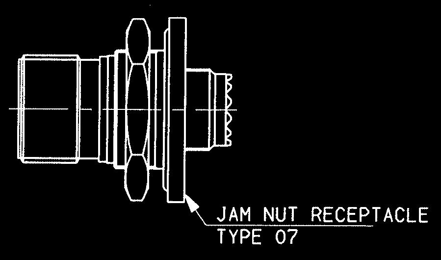
11 38999 Series III Applications Satellite auncher Space station Shuttle hardware Standards ESA/SCC 3401/056/MI-DT class G (QP) Circular connectors with removable crimp contacts ESA/SCC 3401/056 are used with 3401/058 crimp contacts. This series is suitable for Flight Models. Series uses the same components as 3401/056 it is derived from. They are delivered without traceability and AT testing which often complies with Engineering Models requirements. Note : The ESA/SCC 3401/056 are fully intermateable with NATC (NASA Thread Coupling) connectors (according to NASA specification SSQ 21635). Part Number / Ordering information SCC specification number B P N Type of variant ESA not to be modified B testing level not to be modified Shell type 00 : square flange receptacle (front mounting) 06 : plug (with grounding ring) 07 : jam nut receptacle 66 : plug (with grounding ring) with mirror image contact Shell size Contact arrangement (see table page 83) P : pin S : socket Clocking position N : normal (standard clocking position) Other positions : A, B, C, D & E : connectors ordered without contacts ( is not marked on the connector) connectors are only supplied less contacts Series P N Shell type 00 : square flange receptacle (front mounting) 06G : plug («G» for grounding) 07 : jam nut receptacle 66G : plug (G for grounding) with mirror image contact Shell size Contact arrangement (see table page 83) P : pin S : socket Clocking position N : normal (standard clocking position) Other positions : A, B, C, D & E : connectors ordered without contacts ( is not marked on the connector) connectors are only supplied less contacts 69


12 38999 Series III Type 00 : Square flange receptacle Shell size min Max min Max min Max min Max min Max min Max min Max min Max min Max A B C E F G H J 31,50 32,02 32,02 32,02 32,02 32,02 32,02 32,02 32, ,90 20,90 20,90 20,90 20,90 20,90 20,01 20,01 20, ,50 2,50 2,50 2,50 2,50 2,50 2,50 2,50 2, D M12 x 1-6 g M15 x 1-6 g M18x 1-6 g M22 x 1-6 g M25 x 1-6 g M28 x 1-6 g M31 x 1-6 g M34 x 1-6 g M37 x 1-6 g 23,50 24,10 25,90 26,50 28,30 28,90 30,70 31,30 33,00 33,60 36,20 36,80 39,40 40,00 42,60 43,20 45,70 46, ,16 18,36 20,52 20,72 22,91 23,11 24,51 24,71 26,87 27,07 29,26 29,46 31,65 31,85 34,83 35,03 38,00 38, ,99 15,19 18,16 18,36 20,52 20,72 22,91 23,11 24,51 24,71 26,87 27,07 29,26 29,46 31,65 31,85 34,83 35, ,05 3,45 3,05 3,45 3,05 3,45 3,05 3,45 3,05 3,45 3,05 3,45 3,05 3,45 3,71 4,11 3,71 4, ,29 5,69 4,73 5,13 4,73 5,13 4,73 5,13 4,73 5,13 4,73 5,13 4,73 5,13 5,95 6,35 5,95 6, ,5 2,5 2,5 2,5 2,5 2,5 2,5 2,5 2, Type 06G : Plug with grounding ring / Type 66G : Plug with mirror image contact Shell size A C , , , D M12x1-6g M15x1-6g M18x1-6g M22x1-6g M25x1-6g M28x1-6g M31x1-6g M34x1-6g M37x1-6g , , , ,
13 38999 Series III Type 07 : Single hole mounting receptacle Shell size min Max min Max min Max min Max min Max min Max min Max min Max min Max A B C 32,50 32,50 32,50 32,50 32,50 32,50 32,50 32,50 32, ,60 22,60 22,60 22,60 22,60 22,60 20,01 20,01 20, ,38 16,63 18,92 19,17 23,67 23,92 26,82 27,07 30,00 30,25 33,17 33,42 36,35 36,60 39,52 39,77 42,70 42, D M12 x 1-6 g M15 x 1-6 g M18x 1-6 g M22 x 1-6 g M25 x 1-6 g M28 x 1-6 g M31 x 1-6 g M34 x 1-6 g M37 x 1-6 g E F 24,00 27,00 32,00 36,00 37,00 41,00 46,00 50,00 51, ,60 27,40 31,40 32,20 34,50 35,30 37,70 38,50 40,90 41,70 45,60 46,40 48,80 49,60 52,00 52,80 55,20 56, ,20 3,20 3,20 3,20 3,20 3,20 3,20 3,20 3,
14 38999 Series III Part Number / Ordering information SCC specification number B P N Type of variante ESA not to be modified B testing level not to be modified Shell type 00 : square flange receptacle 07 : jam nut receptacle 06 : plug with RFI shielding Dash - mandatory Dash - mandatory Shell type: 9 Dash - mandatory Contact arrangement (see table page 83) P : Pin S : Socket Clocking position N : normal (standard clocking position) Other positions : A, B, C, D & E : connectors ordered without contacts ( is not marked on the connector) Series P N Shell type 00 : square flange receptacle (front mounting) 06G : plug («G» for grounding) 07 : jam nut receptacle 66G : plug (G for grounding) with mirror image contact Shell size Contact arrangement (see table page 83) P : pin S : socket Clocking position N : normal (standard clocking position) Other positions : A, B, C, D & E : connectors ordered without contacts ( is not marked on the connector) connectors are only supplied less contacts 72

15 38999 Series III Connector, Electrical, Triax, Crimp for 34010/56 Connectors 73
16 38999 Series III Contact electrical, Triax, Crimp for 34010/56 Connectors Symb. Min. Min. Min. B B B C ØD ØD2* 6.53 E ØF ØF * After crimping Male Female Contact Type ESA/ESA/SCC P/N SOURIAU P/N MAE B SN 1767K 988-A FEMAE B SN 1767K 988-A 74
 14.5 5.5 8.5 7.")
 34.5 10.5 7 4.")
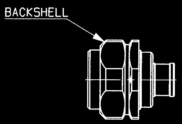
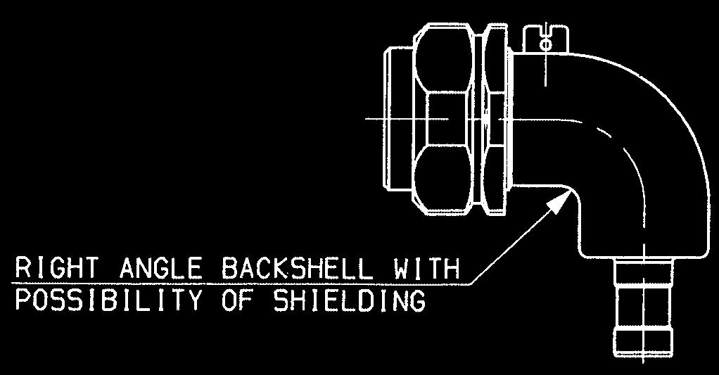
17 38999 Series III Backshell for 3401/056 monotriax connectors Straight Short Backshell ØB C C1 ØD ØD1 20(1) ESA/SCC P/N SOURIAU P/N B A Straight Sheild Termination ØB C C1 ØD ØD1 ± (1) ESA/SCC P/N SOURIAU P/N B A 90 Sheild Termination ØB ØC ØD ØD1 ±0.25 E F 20(1) ESA/SCC P/N SOURIAU P/N B A 75
18 38999 Series III Part Number / Ordering information SCCP specification : pin S : socket number B 00 C P N Type of variant ESA not to be modified B testing level not to be modified Shell type 00 : square flange receptacle 07 : jam nut receptacle Contact post it : long spill C : short spill Shell size: Dash - mandatory Contact arrangement (see table page 83) P : pin S : socket Clocking position N : normal (standard clocking position) Other positions : A, B, C, D & E Suplied only with contacts fitted Series 00 C P N Shell type 00 : square flange receptacle 07 : jam nut receptacle Contact post it : long spill C : short spill Shell size: Dash - mandatory Contact arrangement (see table page 83) P : pin S : Socket Clocking position N : Normal Other positions : A, B, C, D & E Suplied only with contacts fitted 76
19 38999 Series III Connector, Electrical, Square Flange receptacle (triple start, with straight spill contacts) 3401/070 & 00 Series 5 : Shells sizes 9 to ± 0.10 Shells sizes 21 to ± 0.10 ØA 4CM 4CF 4CM 4CF 4CM 4CF 3 Shell size # 22D # 22D # 20 # 20 # 16 # 16 # 22D # # Min Min Min Min Min Min P # 22D PC # 22D P # PC # P # PC # CM: male contact CF: female contact P: long spill PC: Short spill 77
20 38999 Series III Connector, Electrical, Jam-nut mounted receptacle (triple start, with straight spill contacts) 3401/070 & 07 series ØA 2CM 2CF 2CM 2CF 2CM 2CF 3 Shell size # 22D # 22D # 20 # 20 # 16 # 16 # 22D # # Min Min Min Min Min Min P # 22D PC # 22D P # PC # P # PC # CM: male contact CF: female contact P: long spill PC: Short spill 78

21 38999 Series III Hermetic receptacle Applications Satellite auncher Space station Shuttle hardware Standards ESA/SCC 3401/057 Circular connectors with solder contacts ESA/SCC 3401/057 Hermetic series, suitable for Flight Models, is in accordance with MI-DT class H. -H Series uses the same components as 3401/057 it is derived from. They are delivered without traceability and AT testing which these are aceptable for Engineering Models requiremens. Part Number / Ordering information SCC specification number B 00 H P N Type of variant ESA not to be modified B testing level not to be modified Shell type 00 : square flange receptacle 01 : solder mount receptacle 07 : single hole mounting receptacle 77 feedthrough 77 : through bulkhead Hermetic version Shell size Contact arrangement (see table page 83) P : pin only Clocking position N : normal (standard clocking position) Other positions : A, B, C, D & E -H Series 00 H P N Shell type 00 : square flange receptacle 01 : solder mount receptacle 07 : single hole mounting receptacle 77 : through bulkhead Hermetic version Shell size Contact arrangement (see table page 83) P : pin only Clocking position N : normal (standard clocking position) Other positions : A, B, C, D & E 80
22 38999 Series III Hermetic receptacle Type 00 : Square flange receptacle Shell size min Max min Max min Max min Max min Max min Max min Max min Max min Max A B C E F G H J K 5,7 5,7 5,7 5,7 5,7 5,7 5,7 5,7 5, ,4 21,4 21,4 21,4 21,4 21,4 21,4 21,4 21, ,9 2,6 1,9 2,6 1,9 2,6 1,9 2,6 1,9 2,6 1,9 2,6 1,9 2,6 1,9 2,6 1,9 2, ,50 24,10 25,90 26,50 28,30 28,90 30,70 31,30 33,00 33,60 36,20 36,80 39,40 40,00 42,60 43,20 45,70 46, ,16 18,36 20,52 20,72 22,91 23,11 24,51 24,71 26,87 27,07 29,26 29,46 31,65 31,85 34,83 35,03 38,00 38, ,99 15,19 18,16 18,36 20,52 20,72 22,91 23,11 24,51 24,71 26,87 27,07 29,26 29,46 31,65 31,85 34,83 35, ,05 3,45 3,05 3,45 3,05 3,45 3,05 3,45 3,05 3,45 3,05 3,45 3,05 3,45 3,71 4,11 3,71 4, ,29 5,69 4,73 5,13 4,73 5,13 4,73 5,13 4,73 5,13 4,73 5,13 4,73 5,13 5,95 6,35 5,95 6, ,5 10,54 9,5 10,54 9,5 10,54 9,5 10,54 9,5 10,54 9,5 10,54 9,5 10,54 9,5 10,54 9,5 10, Type 01 : Solder mount receptacle Shell size min Max min Max min Max min Max min Max min Max min Max min Max min Max A B C D E F K 9,7 9,7 9,7 9,7 9,7 9,7 9,7 9,7 9, ,8 17,8 17,8 17,8 17,8 17,8 17,8 17,8 17, ,6 1,2 0,6 1,2 0,6 1,2 0,6 1,2 0,6 1,2 0,6 1,2 0,6 1,2 0,6 1,2 0,6 1, ,1 19,9 23,1 26,2 29,4 31, ,2 41, ,4 21,8 24,9 28,1 31,3 33,6 36, , ,1 5,1 5,1 5,1 5,1 5,1 5,1 5,9 5, ,5 10,54 9,5 10,54 9,5 10,54 9,5 10,54 9,5 10,54 9,5 10,54 9,5 10,54 9,5 10,54 9,5 10,
23 38999 Series III Hermetic receptacle Type 07 : Single hole mounting receptacle Shell size min Max min Max min Max min Max min Max min Max min Max min Max min Max A B C E F G H K 29,2 29,2 29,3 29,3 29,3 30,1 30,1 30,1 30, ,6 22,6 22,6 22,6 22,6 22,6 22,6 22,6 22, ,38 16,63 18,92 19,17 23,67 23,92 26,82 27, ,25 33,17 33,42 36,35 36,6 39,52 39,77 42,7 42, , ,6 27,4 31,4 32,2 34,5 35,3 37,7 38,5 40,9 41,7 45,6 46,4 48,8 49, ,8 55, ,1 16,3 19,1 19,4 22,4 22,7 25,6 25,9 28, ,9 32,2 35,1 35,4 38,3 38,6 41,4 41, ,3 5,3 5,3 5,3 5,3 5,3 5,3 5,3 5, ,5 10,54 9,5 10,54 9,5 10,54 9,5 10,54 9,5 10,54 9,5 10,54 9,5 10,54 9,5 10,54 9,5 10, ,6 3,2 1,6 3,2 1,6 3,2 1,6 3,2 1,6 3,2 1,6 3,2 1,6 3,2 1,6 3,2 1,6 3, Feedthrough Receptacle : Shell Type 77 H Shell size min Max min Max min Max min Max min Max min Max min Max min Max min Max A B C D E F G K Ø
24 38999 Series I, II, III & III Hermetic shell size 8TS Contact layouts for circular connector series ESA/SCC 3401/52 (8TS), 3401/044 (), 3401/56 (), 3401/057 (), 3401/070 (), MI-DT series I (8TS), series II (), series III (), Space grade 8TS (series I), (series II), (series III) 35 8TS -H 6 # 22D 35 8TS -H 13 # 22D 35 8TS 22 # 22D 35 8TS -H 37 # 22D 35 8TS 98 8TS -H 3 # TS -H 6 # TS -H 19 # TS 19 # TS 01 8TS 1 # TS 8 # TS 5 # TS TS -H 05 8TS 5 # # 22 2 # TS 8 # 20 4 # TS 04 8TS 4 # TS 4 # TS -H 18 # # 22D 26 # 20 6 # 12 8 # 16 2 # # TS 32 8TS 11 8TS H # 22D 35 8TS 32 # TS 11 # TS 11 8TS 39 8TS size 20 contacts size 16 contacts size 8 contacts 79 # 22D 41# # # # 20 2 # 16 size 4 contacts TS 53 8TS 21 8TS size 12 contacts size 8 triax contact # 22D 35 8TS 53 # TS -H 21 # TS 03* * ESA only 128 # 22D 29 8TS 61 # TS 19 # TS 1 # 8 2 # 4 07* # # # # # 12 7 # 8 83
25 38999 Series: Crimp contacts Crimp contacts Contact size Conductor section AWG # 22 # 22, # 24 & # 26 # 20 # 20, # 22 & # 24 # 16 # 16, # 18 & # 20 # 12 # 12 & # 14 # 8 # 8 & # 10 # 4 # 4 & # 6 # 4 # 8 & # 10 Part number ESA/SCC SOURIAU in ESA/SCC SOURIAU in & accordance with ESA: accordance with ESA: connectors 8TS & connectors connectors connectors pin B B socket B B pin B B socket B B pin B B socket B B pin B B socket B B pin B socket B pin B socket B pin B socket B Tooling for crimp contacts Part number Contact size Designation Crimping tool ocator Insertion and removable plastic tools # 22 pin M22520/2-01 M22520/2-09 M81969/14-01 socket M22520/2-01 M22520/2-07 M81969/14-01 # 20 pin / socket M22520/1-01 M22520/1-04 M81969/14-10 # 16 pin / socket M22520/1-01 M22520/1-04 M81969/14-03 # 12 pin / socket M22520/1-01 M22520/1-04 M81969/14-04 # 8 pin / socket M22520/23-01 # 4 wire 4/6 pin / socket M22520/23-01 # 4 wire 8/10 pin / socket M22520/23-01 *Removable only M22520/23-09 Point : M22520/23-02 M22520/23-11 Point : M22520/ Point : M22520/23-02 M81969/29-02* M81969/29-03* M81969/29-03* M22520/1-01 with locator M

26 38999 Series: Backshells Applications Satellite auncher Space station Shuttle hardware Standards ESA/SCC 3401/062 Accessories for circular connectors ESA/SCC 3401/062 backshells are approved for Flight Models. These accessories are not submitted to ESA/SCC 3401 CHART IV and CHART V. So, they are delivered without AT testing but with a date code limited traceability. The ESA/SCC product are also proposed for Engineering Models. The accessories are without ESA logo printing. Part Number / Ordering information SCC specification number B Variant type B testing level (see table below) (not to be modified) Table of variant types Variant Backshell description For connections Shell size 01 nut 02 nut 03 nut 04 nut 05 nut 06 nut 07 nut 08 nut 09 nut 10 straight cable clamp 11 straight cable clamp 12 straight cable clamp 13 straight cable clamp 14 straight cable clamp 15 straight cable clamp 16 straight cable clamp 17 straight cable clamp 18 straight cable clamp cable clamp cable clamp cable clamp /052 (Series I) 09 /044 (Series II) 08 /052 (Series I) 11 /044 (Series II) 10 /052 (Series I) 13 /044 (Series II) 12 /052 (Series I) 15 /044 (Series II) 14 /052 (Series I) 17 /044 (Series II) 16 /052 (Series I) 19 /044 (Series II) 18 /052 (Series I) 21 /044 (Series II) 20 /052 (Series I) 23 /044 (Series II) 22 /052 (Series I) 25 /044 (Series II) 24 /052 (Series I) 09 /044 (Series II) 08 /052 (Series I) 11 /044 (Series II) 10 /052 (Series I) 13 /044 (Series II) 12 /052 (Series I) 15 /044 (Series II) 14 /052 (Series I) 17 /044 (Series II) 16 /052 (Series I) 19 /044 (Series II) 18 /052 (Series I) 21 /044 (Series II) 20 /052 (Series I) 23 /044 (Series II) 22 /052 (Series I) 25 /044 (Series II) 24 /052 (Series I) 09 /044 (Series II) 08 /052 (Series I) 11 /044 (Series II) 10 /052 (Series I) 13 /044 (Series II) 12 Variant Backshell description For connections Shell size cable clamp /052 (Series I) 15 /044 (Series II) cable clamp /052 (Series I) 17 /044 (Series II) cable clamp /052 (Series I) 19 /044 (Series II) cable clamp /052 (Series I) 21 /044 (Series II) cable clamp /052 (Series I) 23 /044 (Series II) cable clamp /052 (Series I) 25 /044 (Series II) nut /056 (Series III) straight cable clamp /056 (Series III) cable clamp /056 (Series III)


 01 to 09 variants (2) 28 to 36 variants Straight cable clamp Shell A B C D E F size (1) (2) (1) (2) Max (1) UNEF-2B (2) min 08/09 27,5 27,9 19,1 21,79 23,1.")
27 38999 Series: Backshells Dimensions (in mm/inch) Nut Shell A B C Ø D Ø E size (1) (2) (1) (2) Max (1) UNEF-2B (2) min 08/09 13,7 16,8 19,1 21,79 6, M12 x 1-6h 6, /11 13,7 16,8 21,5 24,99 6, M15 x 1-6h 9, /13 13,7 16,8 25,4 29,39 6, M18 x 1-6h 12, /15 13,7 16,8 27,9 32,49 6, M22 x 1-6h /17 13,7 16,8 31,8 35,71 6, M25 x 1-6h 19, /19 13,7 16,8 35,6 38,5 6, M28 x 1-6h 21, /21 13,7 16,8 38,1 41,7 6, M31 x 1-6h 24, /23 13,7 16,8 41,9 44,91 6, M34 x 1-6h 27, /25 13,7 16,8 44,5 47,98 6, M37 x 1-6h 30, Notes : (1) 01 to 09 variants (2) 28 to 36 variants Straight cable clamp Shell A B C D E F size (1) (2) (1) (2) Max (1) UNEF-2B (2) min 08/09 27,5 27,9 19,1 21,79 23, M12 x 1-6h 2,49 5,94 21, /11 27,9 27,9 21,5 24,99 23, M15 x 1-6h 3,89 5,49 22, /13 30,5 30,5 25,4 29,39 25, M18 x 1-6h 4,83 8,33 27, /15 31,8 31,8 27,9 32,49 26, M22 x 1-6h 6,6 11,61 29, /17 34,3 24,3 31,8 35,71 29, M25 x 1-6h 7,19 15, /19 40,6 40,6 35,6 38,5 35, M28 x 1-6h 8,26 16,1 38, /21 43,2 43,2 38,1 41,7 38, M31 x 1-6h 8,71 17,73 40, / ,9 44,91 42, M34 x 1-6h 9,68 20,9 43, /25 49,5 49,5 44,5 47,98 44, M37 x 1-6h 10,62 21,67 45, Notes : (1) 10 to 18 variants (2) 37 to 45 variants 90 cable clamp Shell A B C D E F G size (1) (2) (1) (2) (1) (2) (1) (2) min 08/09 30,5 35,1 19,1 21,79 25,7 29,5 see above 2,49 5,94 21,6 25, /11 30,5 35,1 21,5 24,99 25,7 29,5 see above 3,89 5,49 22,5 27, /13 35,6 37,1 25,4 29,39 30,7 31,5 see above 4,83 8,33 27,9 27, /15 36,8 41,4 27,9 32,49 32,0 35,8 see above 6,6 11,61 29,2 31, /17 40,6 45,7 31,8 35,71 35,8 40,1 see above 7,19 15,6 33,0 33, /19 43,2 46,2 35,6 38,5 38,4 40,6 see above 8,26 16,1 38,1 38, /21 47,0 48,3 38,1 41,7 42,2 42,7 see above 8,71 17,73 40,6 40, /23 49,5 51,1 41,9 44,91 44,7 46,2 see above 9,68 20,9 43,2 44, /25 53,3 54,6 44,5 47,98 48,5 49,0 see above 10,62 21,67 45,7 47, Notes : (1) 19 to 27 variants (2) 46 to 54 variants 86
Amphenol RF. Type N. Type N Connectors. Type N. Description. Features/Benefits. Applications
 Amphenol RF 144 Connectors Description Named after Paul Neill of Bell Labs after being developed in the 1940 s, the offered the first true microwave performance. The connector was developed to satisfy
Pegasus Series Amphenol Pcd
 Pegasus Series Amphenol Pcd Amphenol Pcd is one of the world s leading suppliers of interconnect products for Military, Commercial Aerospace and Industrial applications. Located north of Boston in Beverly,
*NOTE: 75 OHM SERIES CONNECTORS ARE NOT INTERMATEABLE WITH THE 50 OHM SERIES.
 The Connex N connectors with screw coupling are fully interchangeable with N connectors made to the MIL-C-39012 specification. Designed for use in all systems where very good R.F. and mechanical performance
PRODUCT SPECIFICATION
 MINI-FIT SR. SERIES 1.0 SCOPE This specification covers the 10.00 mm / (.394 in.) centerline tin and gold plated connector series, single and dual row versions in wire to wire and wire to printed circuit
Outer contact 1.0 milliohm max.
 MCX.4 11/27/01 5:17 PM Page 17 Connex MCX Series connectors are ideal for applications and designs where weight and space savings are critical. This series has a 50 ohm impedance structure which operates
SMB/SMC Coaxial Connectors
 The Amphenol SMB/SMC subminiature coaxial connectors with 50 ohm impedance are for applications to 4 GHz (SMB) or 10 GHz (SMC). Generally less expensive then SMA, these connectors are used primarily in
D-Sub Vertical Surface Mount Connectors RoHS compliant Economical Interface Solution for SMT Applications
 D-Sub Vertical Surface Mount Connectors RoHS compliant Economical Interface Solution for SMT Applications General In the manufacture of assemblies, the trend toward using SMT components is unbroken. Whereas
Luminus Series Amphenol Pcd
 Luminus Series Amphenol Pcd Amphenol Pcd is one of the world s leading suppliers of interconnect products for Military, Commercial Aerospace and Industrial applications. Located north of Boston in Beverly,
RESISTORS, HEATERS, FLEXIBLE, SINGLE AND DOUBLE LAYER. ESCC Detail Specification No. 4009/002
 Page 1 of 16 RESISTORS, HEATERS, FLEXIBLE, SINGLE AND DOUBLE LAYER ESCC Detail Specification Issue 8 February 2018 Document Custodian: European Space Agency see https://escies.org PAGE 2 LEGAL DISCLAIMER
PRODUCT SPECIFICATION. SFP+ Cage and Cage Assembly 1 of 8 A
 SFP+ Cage and Cage Assembly 1 of 8 A 1.0 Objective This specification defines the performance, test, quality and reliability requirements of the _Small Form-factor Pluggage (SFP+) product. 2.0 Scope This
COMPONENT SPECIFICATION M80-7XX SERIES CONNECTORS - THREE ROW
 COMPONENT SPECIFICATION M80-7XX SERIES CONNECTORS - THREE ROW JUN 200 CONTENTS: SECTION TITLE PAGE Description of Connector and Intended Application 2 2 Marking of Connector and/or Package 2 3 Ratings
EPIC Rectangular Connector Inserts. HBE Series. Technical Data Number of Contacts:
 HBE Series HBE series inserts provide reliable termination and performance in the vast majority of medium power and control applications. Methods of termination include screw, crimp, and spring cage clamp.
Pegasus Series Amphenol Pcd
 is one of the world s leading suppliers of interconnect products for Military, Commercial Aerospace and Industrial applications. Located north of Boston in Beverly, Massachusetts, the company designs and
RECTANGULAR CONNECTORS
 RECTANULAR CONNECTORS CN-360 SERIES EATURES Many applications Various connectors are available for connection by means of soldering, wire wrapping, crimping, PC board mounting, and insulation displacement
MDM Accessories
 Accessories General Hardwares are the screwlock assemblies or the brackets used for the mounting of connectors on panels or PC, or for the fixing of plugs and receptacles. They are not fixed on the connectors
ibridge and ibridge Ultra
 2.00 mm Board to Cable Connectors ED. 06 10.2016 Catalog EA IB001 erni.com erni.cn TABLE OF CONTENTS OVERVIEW General 03 Technical Details 04 Features 05 Electrical and Mechanical Characteristics 10 Ordering
Glenair Well-Master TM 260 Micro-D Withstands Extreme High Temperature
 Section : Well-Master Micro- + P eader lenair Well-Master TM Micro- Withstands Extreme igh Temperature Standard Micro- connectors are rated for +125. lenair's MWM Micro- can withstand +150 continuous operating
SMB Series. SMB Series. Specifications. Interface Dimensions. Available in 50 Ohm and 75 Ohm versions. Snap-on interface reduces installation time.
 Available in 50 Ohm and 75 Ohm versions. Snap-on interface reduces installation time. Self-cleaning outer spring withstands moderate vibration. Small & lightweight. Frequency Range: Up to 4 GHz Specifications
Datamate Specification. Pin Numbering. Mating Profiles. Materials. Mechanical. 3 Row 6.
 Datamate Specification Materials Mechanical Mouldings: Glass-filled thermoplastic UL94V-0 Female contacts: rass shell, with eryllium opper inner contact Male contacts: Phosphor bronze Finish: See individual
Teledyne Oil & Gas North Williamson Blvd. Daytona Beach, FL USA (phone) (fax)
 (fax)") PER CO # 33537 Approved By: M. Bartell Originator: Checked By: S. Jackson B. Cornelius 1 of 8 ODN-084-23 23 TITLE: Installation and Operation Manual for Dry- Teledyne Oil & Gas 1026 North Williamson Blvd.
PER CO # 33537 Approved By: M. Bartell Originator: Checked By: S. Jackson B. Cornelius 1 of 8 ODN-084-23 23 TITLE: Installation and Operation Manual for Dry- Teledyne Oil & Gas 1026 North Williamson Blvd.
Plok. Rapid Mating Multi-Pin Industrial Connector. Amphenol Industrial Sine Systems * Pyle Connectors Corporation
 - Plok Rapid Mating Multi-Pin Industrial onnector mphenol Industrial Sine Systems * Pyle onnectors orporation eatures and enefits Rapid mate spring loaded, push to mate, pull to unmate coupling system
BNC 50 Ohm. BNC - 50 Ohm. Aviel Electronics 3060 East Post Road, Suite 100, Las Vegas NV 89120
 Find Reverse Polarity on page 51-56 male BNC 50 Ohm female specifications ELECTRICAL SPECIFICATIONS Impedance: 50 Ω Working voltage rating: 500 VRMS @ sea level Frequency range: 0-4 GHz MECHANICAL SPECIFICATIONS
GENERAL APPLICATION NOTES
 GENERAL APPLICATION NOTES There are common considerations when using our connectors. Additional considerations may apply based on the particular connector being used, the application, and conditions in
MMCX Coaxial Connectors
 The Amphenol MMCX series is the next generation of microminiature connectors. Offering a reliable broadband performance from DC to 6 GHz. These 50 ohm connectors incorporate the industryapproved MMCX interface,
JUMO dtrans p30 Pressure Transmitter
 609 Fulda, Germany Postal address: 605 Fulda, Germany Phone: +49 661 600-0 Fax: +49 661 600-607 Phone: +44 179 6 55 Data Sheet 40466 Page 1/6 JUMO dtrans p0 Pressure Transmitter General application Pressure
Prewired position switches FA series
 2 Prewired position switches FA series Selection diagram 01 08 10 11 1 15 1 02 external rubber gasket external rubber gasket 1 51 52 54 55 56 5 ACTUATORS adjustable lever safety adjustable lever 41 45
TURQUOISE SWITCHES ABJ (BJ) SWITCHES
 SWITCHES") Ultra-miniature Size Sealed Switches TURQUOISE SWITCHES ABJ (BJ) SWITCHES Terminal type Mounting hole 2.3 mm type FEATURES Ultra-miniature size, High sealing performance sealed switches Elastomer double
Ultra-miniature Size Sealed Switches TURQUOISE SWITCHES ABJ (BJ) SWITCHES Terminal type Mounting hole 2.3 mm type FEATURES Ultra-miniature size, High sealing performance sealed switches Elastomer double
UHF/Mini-UHF Coaxial Connectors
 UHF/MiniUHF Coaxial Connectors The Amphenol UHF/MINIUHF connectors are popular and economical, used when impedance mating is not required. General purpose units are designed to operate satisfactorily op
CONTENTS PAGE. Introduction... HUM 2 Availability... HUM 2 Applications... HUM 2
 CONTENTS PAGE SECTION PAGE erjjboseries Introduction... HUM 2 Availability... HUM 2 Applications... HUM 2 Testing... HUM 2 Part Number System... HUM 2 General Information... HUM 2 Ampacity Chart for Standard
![[Instruments for vacuum measurement, checking and adjustment] 3](/thumbs/94/121874202.jpg "[Instruments for vacuum measurement, checking and adjustment] 3")
3M Telecommunications Solutions for Networks. Quante QSA (= LSA plus) System Catalogue. Innovation
 System Catalogue. Innovation") 3M Telecommunications Solutions for Networks Quante QSA (= LSA plus) System Catalogue Innovation IDC Modules Overview 3M Quante Cross Connect System QSA QSA Series 1 Connection modules for screw fixing
3M Telecommunications Solutions for Networks Quante QSA (= LSA plus) System Catalogue Innovation IDC Modules Overview 3M Quante Cross Connect System QSA QSA Series 1 Connection modules for screw fixing
Pressure Transmitter P41
 SENSORS FOR AND BIOPHARMA. Product Information P41 Pressure Transmitter P41 Application/Specified usage Pressure measurement in pipes and tanks For process temperatures up to 250 C (428 F) with optional
Primary Terminals & Connectors
 Primary & Pure electrolytic copper with electro-tin plating for corrosion resistance Deep internal serrations promote firm wire grip for maximum strength Insulation (where applicable) is color coded to
PN LINE. Technical remarks PN 11 PN 13 PN 14 PN 15 PN 17 PN 18 PN 20 PN 23 PN 25 PN 26 PN 27 PN 28 PN 29 PN 37 PN 38 PN 39 PN 40 PN 43 PN 10 8_9 10_12
 PN LINE PN 11 PN 13 PN 14 PN 15 PN 17 PN 18 PN 20 PN 23 PN 25 PN 26 PN 27 PN 28 PN 29 PN 37 PN 38 PN 39 PN 40 PN 43 PN 10 Technical remarks PN 11 PN 13 PN 14 PN 15 PN 17 PN 18 PN 20 PN 23 PN 25 PN 26 PN
Pilot Check Valve: Metal Body Type
 INFORMATION Pilot Check Valve: Metal Body Type The use of a metal body improves strength and environmental resistance. Temporary intermediate stops are possible. *1 *1 Precise intermediate stops are not
Flow controller Type ED/CCB311 Instruction manual
 Flow measurement Flow controller Type ED/CCB311 1. GENERAL DESCRIPTION page 4 2. DETAILED DESCRIPTION page 4 3. PIPE - EXPLOITATION page 5 4. PREVENTIVE MAINTENANCE page 5 5. REPLACEMENT OF THE CONTACT
Position switches FP series
 A Position switches FP series Selection diagram 0 08 8 9 0 0 0 Ø 8 mm Ø, mm external rubber stainless steel stainless steel fiber glass rod gasket sphere sphere adjustable lever safety adjustable lever
MUELLER. A Wall Type. Indicator Post. Reliable Connections. General Information 2. Technical Data/ Dimensions 3. Installation 4-5.
 Installation Instructions manual MUELLER table of contents PAGE A-20814 Wall Type General Information 2 Technical Data/ Dimensions Installation 4-5 Maintenance 6 Parts 7 Indicator Post! WARNING: 1. Read
APPLICATIONS ROV & AUV SEISMIC PRODUCTION SYSTEMS DOWNHOLE JUMPER & CABLE SYSTEMS DRILLING CONTROL
 APPLICATIONS ROV & AUV SEISMIC PRODUCTION SYSTEMS DOWNHOLE JUMPER & CABLE SYSTEMS DRILLING CONTROL ROV & AUV PRODUCTS GRE (Glass Reinforced Epoxy) CS-MS 55 & 66 SERIES MINI-CON HUMMER GLOBE-CON ALL-WET
Pneumatic Target Transfer System Model PT01
 Pneumatic Target Transfer System Model PT01 Technical Data Sheet ELEX Commerce LLC Bul. M. Pupina 10Z/IV 11070 Belgrade, Serbia www.elexcomm.com February 2018. Page 2/13 REVISION HYSTORY No. Description
Pneumatic spool valve islands
 Pneumatic spool valve islands P7.GB.R MEGA SPOOL VALVE ISLANDS MEGA pneumatic spool valve islands offer maximum performance along with flexibility, easy installation and simple operation. Due to their
1mm Pitch SMT Board-to-Board Connectors(Standard Interface Connector Compliant with VESA FPDI-1)
") 1mm Pitch SMT Board-to-Board Connectors(Standard Interface Connector Compliant with VESA FPDI-1) DF Series Features 1. Compliant with the VESA FPDI-1 Standard Interface Connector The and contact connectors
1mm Pitch SMT Board-to-Board Connectors(Standard Interface Connector Compliant with VESA FPDI-1) DF Series Features 1. Compliant with the VESA FPDI-1 Standard Interface Connector The and contact connectors
PURA. Pure Gas Dewpoint Transmitter. Users Guide
 PURA Pure Gas Dewpoint Transmitter Users Guide Issue January 2003 Page 2 Table of Contents SECTION PAGE 1 Product Overview 3 2 Preparation 3 3 Installation 3 3.1 PURA Premium & OEM Dewpoint Transmitter
IAPMO GUIDE CRITERIA FOR BALL VALVES IAPMO IGC PURPOSE
 INTERNATIONAL ASSOCIATION OF PLUMBING AND MECHANICAL OFFICIALS IAPMO GUIDE CRITERIA FOR BALL VALVES IAPMO IGC 157-20067 1 PURPOSE 1.1 The purpose of this standard is to establish an acceptable standard
May08 Rev B
 Qualification Test Report 0.64 mm Generation Y Terminal 501-657 20May08 Rev B 1. INTRODUCTION 1.1. Purpose Testing was performed on the Tyco Electronics 0.64 mm Generation Y Terminal to determine its conformance
Technical Specification
 Medical Gas Terminal Units (Gas Outlet Points) Technical Specification EN 9170-1 Terminal Unit Product Description CPX Terminal Units comprise a first fix, second fix and check valve. The first fix assembly
Bourdon tube pressure gauges with glycerine filling, for chemical applications EN 837-1
 Application For aggressive gaseous and liquid media which are not highly viscous and do not crystallize. Suitable for use in corrosive atmospheres. For measurement in areas subject to high vibration levels
Proportional pressure regulators VPPE
 Proportional pressure regulators VPPE Proportional pressure regulators VPPE Product range overview Function Version Pneumatic connection Proportional pressure regulator Nominal size for pressurisation/
RTA Series 1 4 Poles Coded Rotary Switches
 1 4 Poles oded Switches Features/Benefits PB or hand soldering versions Bushing mounting Multiple poles Decimal and hexadecimal codes Screwdriver slot or extended actuator RoHS ompliant Typical Applications
Product Technical Bulletin #48
 AN INTEGRATED SOLUTIONS PROVIDER Product Technical Bulletin #48 Current-Carrying Capacity of R-Series Connectors AirBorn Proprietary Page 1 AN INTEGRATED SOLUTIONS PROVIDER R-Series Current-Carrying Capacity
Operating Instructions
 Operating Instructions Light-metal Ex d enclosures / flameproof enclosure > 8265/0 Empty enclosure > 8265/4 Control panel, integrated in Ex e enclosure > 8265/5 Control panel Table of Contents 1 Table
RECTANGULAR CONNECTORS
 RETNGULR ONNETORS FN360 Series FN-365P FN-365J FN-364P FN-364P FN-364J FN-364J FN-365P FN-365J FN-364P FN-364J FN-362J FN-363J FN-365P FN-367J FN-365P FN-364P FN-361P With type cover FN-365J FN-364P With
Inductive Linear Displacement Transducers Model IW 260 Measuring strokes: 80 mm, 170 mm, 240 mm, 360 mm
 Inductive Linear Displacement Transducers Model IW 260 Measuring strokes 80, 170, 240, 360 Document no. IW 100 HE Date 1.07.201 Contactless, robust sensor system Infinite resolution, no hysteresis Calibrated
TA-FUSION-P. Combined control & balancing valves Pressure independent combined balancing and control valves with independent EQM characteristics
 TA-FUSION-P Combined control & balancing valves Pressure independent combined balancing and control valves with independent EQM characteristics IMI TA / Control valves / TA-FUSION-P TA-FUSION-P These innovative
DMK 458. Pressure Transmitter for Marine and Offshore. Ceramic Sensor. accuracy according to IEC 60770: standard: 0.25 % FSO option: 0.
 Pressure Transmitter for Marine and Offshore Ceramic Sensor accuracy according to IEC 60770: standard: 0.5 % FSO option: 0. % FSO Nominal pressure from 0... 40 mbar up to 0... 0 bar Output signals -wire:
Pressure Measurement Single-range transmitters for general applications
 Siemens A 207 Overview Application The SITRANS P Compact pressure transmitter is designed for the special requirements of the food, pharmaceutical and biotechnology industries. The use of high-grade materials
MX150 System Sealed Product Line
 MX150 System Sealed Product Line 1 of 74 Table of Contents Section 1: Product Introduction Section 2: Product Summary Section 3: Connector Assembly Section 4: Connector Mating Section 5: Service Instructions
1mm Pitch SMT Board to Board Connector(Standard Interface Connector Compliant with VESA FPDI-1)
") 1mm Pitch SMT Board to Board Connector(Standard Interface Connector Compliant with VESA FPDI-1) DF Series Features 1. Compliant with the VESA FPDI-1 Standard Interface Connector The and contact connectors
1mm Pitch SMT Board to Board Connector(Standard Interface Connector Compliant with VESA FPDI-1) DF Series Features 1. Compliant with the VESA FPDI-1 Standard Interface Connector The and contact connectors
Expert Hydrostatic Level Transmitters
 Expert Hydrostatic s General Features MJK Expert hydrostatic level transmitters are designed for level measurement by submerging the transmitter in open channels, drains and tanks. Expert hydrostatic level
INSTRUCTION MANUAL Pressure Relief Device LPT
 INSTRUCTION MANUAL Pressure Relief Device LPT 5COV475800 LPT REV00 CONTENT: 1 SAFETY 1.1 Safety instructions 2 1.2 Specified applications 2 1.3 Safety notes on the equipment operation 2 2 PRESSURE RELIEF
Electromechanical pressure switches
 References : pages / and / page /5 Presentation Functions Pressure switches type XMX and XMA are switches for control circuits, with an adjustable differential. They are used to control the pressure of
Pneumatic valve islands
 Pneumatic valve islands The MEGA solenoid air operated spool valve JOUCOMATIC offers a concept of solenoid air operated spool valves which can be fitted together to form islands. Due to its new patented
Electromechanical pressure switches
 Presentation Electromechanical pressure switches OsiSense XM For power circuits, type XMP Presentation Pressure switches type XMP are switches for power circuits (direct switching), with an adjustable
RTA Series 1 4 Poles Coded Rotary Switches
 1 4 Poles oded Switches Features/Benefits PB or hand soldering versions Bushing mounting Multiple poles Decimal and hexadecimal codes Screwdriver slot or extended actuator RoHS ompliant Typical Applications
CPTCONNECTOR. Board-to-wire. Features. Specifications
 CPTCONNECTOR Board-to-wire HIT AIT AIT- HCM SHC HCH MIO CPT BMD RAD CIT GIT0P GITP HIC SNA NAC- SQS SQM SQH SQS Developed in pursuit of miniaturization and low profile as PC board connector for automobile.
Pressure Switches Application Guideline
 Pressure Switches Application Guideline Product Overview The Fema Pressure Switch product portfolio provides devices suitable for many applications. The portfolio contains Special functions and equipment
Gas density monitor With integrated transmitter Model GDM-100-TI
 SF 6 gas solutions Gas density monitor With integrated transmitter Model GDM-100-TI grid Products WIKA data sheet SP 60.05 for further approvals see page 5 Applications Gas density monitoring of closed
AMS 2710 PCB pressure sensor module with V output
 FEATURES Universal pressure sensor module with 0.. 10 V voltage output Fully calibrated and temperature compensated sensor module Variants for (bidirectional) differential, gage, absolute and barometric
Monitoring device NTS 30
 P R O D U C T I N F O R M A T I O N Electronic level- and temperature monitoring device Monitoring device NTS 30 Contents Description Description... 2 Operating... 3 Design and electrical data... 4 Circuit
INSTRUCTIONS 360 Y-DROP HAGIE STS 2015
 INSTRUCTIONS 60 Y-DROP HAGIE STS 05 INSTRUCTIONS 60 Y-DROP HAGIE STS 05 INTRODUCTION Before beginning, it s important to know where each mounting bracket fits relative to the row spacing involved. The
Zelio Relays RSL Slim Interface Plug-In Relays
 Zelio Relays RSL Slim Interface Plug-In Relays Catalog 8501CT0901 2009 Class 8501 CONTENTS Description............................................. Page Introduction.................................................3
Instruments AQDC. Aluminium Quick Disconnects. Light-weight, quick and reliable method a making a number of pneumatic connections.
 AQDC Aluminium Quick Disconnects Instruments Light-weight, quick and reliable method a making a number of pneumatic connections. 8, 16, 24 and 32 port stainless steel quick disconnects. Available with
TIGHTNESS. Glass sealing Thanks to our glass-sealing technology, ODU products can meet the most demanding tightness requirements.
 TIGHTNESS Glass sealing Thanks to our glass-sealing technology, ODU products can meet the most demanding tightness requirements. ODU has the necessary expertise for developing and manufacturing connectors
K13.12 FACE FIXED PANIC EXIT DEVICE K13 DOORS
 K13 DOORS K13.12 FACE FIXED PANIC EXIT DEVICE 01.03.2018 Waregemstraat 5-9870 Zulte - Belgium - T. +32 9 388 88 81 - F. +32 9 388 88 21 - commercial@sobinco.com - www.sobinco.com CONTENTS 1. Base set n
E10 E10 E10 E10 E10 E10 E10 E10 E10 E10 E10 E10 E10 E10. Cable gland Series 8161/7, 8161/8. Installation Equipment and Accessories E10/1.
 > Explosion protection type "Increased safety" > Degree of protection IP68 > Ex e and Ex i versions > Integrated blind plug (accessory) for closing unused cable glands > Cable diameter ranges from 1 to
ED 701 Hygenic Pressure Transmitter
 ED 701 Hygenic Pressure Transmitter Hygienic process connections Complete range of electrical connections 4... 20 ma and Voltage outputs Accuracy: 0.1%, 0.2% and 0.4% FS Quick response time < 25 ms (Option
HERZ-Motorised flow controler
 HERZ-Motorised flow controler Control and regulating valve Data sheet 46, Issue 214 Dimensions in mm 4 close dimension 9,35 M DN G H1 H2 H2 + Actuator B1 B2 1 2 M 1 46 11 15 3/4 G 66 59 73 134 49 63 48
Compact Pressure Switch
 Compact Pressure Switch Series ZSE1 (For Vacuum)/SE1 (For Positive Pressure) For General Pneumatics Can be integrated with ZM ejector system. RoS Variable hysteresis 1 to 10% of set pressure (Variable)
ST Connectors & Adapters
 Features & Benefits High performance singlemode and multimode pre-polished ferrules ST* compatible bayonet coupling Field installable Standard crimp and crimpless screw type KEVLAR retention Variety of
I.H.S INSTALLATION INSTRUCTIONS
 I.H.S INSTALLATION INSTRUCTIONS TOOLS REQUIRED The following tools will be required for installation of your I.H.S. system. Item Qty Needed 9/16 Open End Wrench 2 3/4 Open End Wrench 1 1/2 Open End Wrench
Low Wind High Yields Series
 Low Wind High Yields Series Wind Turbines USER S MANUAL Introduction Low Wind High Yields Series rotor blades apply the latest advanced thermoplastic engineering and are manufactured by precision injection
HEAVY DUTY PNEUMATIC
 HEAVY DUTY PNEUMATIC Series A4 MEDIUM DUTY HYDRAULIC Series H4 PERMANENTLY LUBRICATED HEAVY DUTY PNEUMATIC Series L4 586.778.7680 SERIES A4/L4/H4 39 A4/L4/H4 FEATURES 1 1 9 9 12 8 7 5 12 3 13 4 10 2 11
CFSW. Hinges with built-in safety multiple switch
 CFSW. Hinges with built-in safety multiple switch ELESA Original design Elesa Standards Main dimensions Fitting Weight Code Description L B f ±0.2 f 1 ±0.2 H h 1 h 2 d 3 d 4 C [Nm]# g 426601 CFSW.110-6-2NO+2NC-C-A
Compact differential pressure switch Flameproof enclosure Ex d Models DE, DEC
 Mechatronic pressure measurement Compact differential pressure switch Flameproof enclosure Ex d Models DE, DEC WIKA data sheet PV 35.41 Process Compact Series Applications Differential pressure monitoring
MULTIFUNCTIONAL CONTROL FOR GAS BURNING APPLIANCE
 SIT Group SIT -3- SIGMA MULTIFUNCTIONAL CONTROL FOR GAS BURNING APPLIANCE 9.955. Subject to change without notice Application Domestic gas appliances: central heating boilers, combi boilers, instantaneous
One-touch Fittings Manifold. Porting. One-touch fitting. One-touch fitting. One-touch fitting. One-touch fitting. One-touch fitting.
 One-touch Fittings Manifold Series KM RoHS Compact piping possible. Manifold piping possible. Many varieties (0 types) are available. s give the most efficient operation. KM1 KM1 orting Rc female thread
Conductor Bushings Series 8174
 > Current lead-in for Ex d enclosures > 1 to 72 conductors combined in one current lead-in > Series screw-in plug-in > For voltages up to max. 1 V > For size conductor up to 7 mm 2 www.stahl.de 3163E The
Magnetic level switch type MR783 Instruction Manual
 Magnetic level switch Magnetic level switch type MR783 1. DESCRIPTION page 3 1.1 Operation page 3 1.2 Application page 3 1.3 Description page 3 2. SPECIFICATIONS page 3 2.1 Service Conditions page 4 2.2
ENGLISH Datasheet IEC Miniature Thermocouple Connector Socket with Stainless Steel mounting bracket Types K, J, T, E, N, B & Copper (IEC Colour Code)
") ENGLISH Datasheet IEC Miniature Thermocouple Connector Socket with Stainless Steel mounting bracket Types K, J, T, E, N, B & Copper (IEC Colour Code) Miniature size in-line Thermocouple Socket with stainless
ENGLISH Datasheet IEC Miniature Thermocouple Connector Socket with Stainless Steel mounting bracket Types K, J, T, E, N, B & Copper (IEC Colour Code) Miniature size in-line Thermocouple Socket with stainless
Ultrasonic. 58 Overview VEGASON 60 VEGASON 61, 62, 63
 Ultrasonic 58 Overview VEGASON 60 VEGASON 61, 62, 63 57 Overview VEGASON Area of application The ultrasonic sensors of the VEGASON series are suitable for non-contact level measurement of liquids and bulk
CCSSL35 Carry out the wiring and testing of electrical circuits and equipment
 Carry out the wiring and testing of electrical circuits and equipment Overview This standard is about the basic competences that you need to wire up and test electrical equipment and circuits for the theatre
EPIC Rectangular Connectors HBE Series
 HBE Series The HBE series inserts are suitable for applications with high voltages and current. The inserts can be terminated in a variety of ways: screw, crimp, or spring cage clamp. TECHNICAL DATA Number
IP 69 Protection against water under pressure
 44 he European echnical Standard DIN EN 50 262 Metric cable glands for electric installations - the end of the PG Cable glands threads. he technical standards Cable Glands for cables and conductors with
Item No.: /
 mounting types; for parallel or perpendicular mounting; pin spacing mm / 0197 in; 4-pole - Item No: 769- Male connector; with CAGE CLAMP connection and fixing flanges; for screw or similar mounting types;
FITTINGS THREAD LUBRICANTS. Fittings 20,000 PSI
 Jetstream offers a wide variety of fittings with various connection types to fit your 20,000 psi application needs. The standard connection types, Type M, MP, and MP Tube lance, are available in standard
Product Specification Spring Finger
 Product Specification 108-115008-3 Spring Finger Restricted to Sony Ericsson Mobile Communications 1. SCOPE 1.1. Content This specification covers the requirements for product performance test methods
Mechanical pressure switches
 18 Technical features / Advantages Diecast aluminium housing IP 54 or IP 65 version also available Wall mounting or directly on the pressure line Switching element (microswitch) Lead sealable setpoint
HOW TO USE THIS MANUAL
 HOW TO USE THIS MAUAL This manual is organized first by HAVERHILL Cable groups and then by the types of RFI connectors available for each group. The connector lists are divided into subgroups by interface
Handling instructions for GISMA connectors HI
 Content 1. GENERAL... 3 2. SCOPE... 3 3. PROTECTION, HANDLING AND SHIPMENT... 3 4. UNPACKING... 4 5. STORAGE... 4 5.1. Short Term Connector Storage... 4 5.2. Long Term Connector Storage... 4 6. Jumper
Proton Monitor Thermal Vacuum Test Procedure GP-B P0635
 Procedure Number P0635 Rev Page Count: 7 W. W. Hansen Experimental Physics Laboratory STANFORD UNIVERSITY STANFORD, CALIFORNIA 94305-4085 Gravity Probe B Relativity Mission Proton Monitor Thermal Vacuum