2014 Zee 2 Owner/Operator Manual
|
|
|
- Edmund Simon
- 5 years ago
- Views:
Transcription


1 2014 Zee 2 Owner/Operator Manual Serial numbers 14 and higher
2 About This Manual Congratulations on the purchase of your new Dixie Chopper mower! When operated and maintained as directed in this manual, Dixie Chopper is confident that this mower will provide you with years of excellent performance, durability, and trouble free service. Should you ever have any questions regarding the operation, maintenance, or safety of your mower, please contact your authorized Dixie Chopper dealer who has been specially trained in the operation and service of Dixie Chopper mowers. Please take time to record the information about your new Dixie Chopper mower in the space below for future reference. Such information may be needed when you contact your authorized Dixie Chopper dealer with questions. The general operation, adjustment, and maintenance procedures contained in this manual are meant for both the beginner and the experienced Dixie Chopper operator. Operating conditions vary greatly, as do individual skill sets, so take time to learn how to safely operate this machine. This owner s manual is considered a permanent part of the mower. It must be available to all of the operators and/or person(s) servicing the mower. Should the mower be resold, this manual must remain with the mower. Illustrations and photographs used in this manual were current as of date of print. Despite this effort, production changes may have occurred after the time of the purchase of your Dixie Chopper; therefore, your unit may vary slightly from what is depicted in this manual. All information, illustrations, and specifications contained in this manual were in effect at the time of publication. Dixie Chopper reserves the right to change, modify, and/or discontinue specifications and/or design without notice. If there is a change that has been made to your mower which is not shown or reflected in this manual, please see your authorized Dixie Chopper dealer before operating and/or servicing equipment. Authorized Dealer: Model #: Serial #: Engine Model #: Engine Serial #: Date purchased: II
3 Table of Contents Topic Page# General Precautions...1 Safety Information...3 Warranty...5 Routine Maintenance...8 Maintenance Schedule...8 Maintenance Record...9 Maintenance Points...10 Start-up & Controls...11 Safety Interlock System...11 Starting the Mower...12 Controls...13 Operation...14 Cut Height Setting...14 Mowing Speed...14 Mowing...15 Shutdown...15 Shutdown Procedures...15 Moving the Mower Without Power...15 Bypass Valve...15 Maintenance & Repair...16 Blade Replacement...16 Under Deck Cleaning...16 Battery Maintenance...16 Mower Cleaning & Off-Season Storage...16 Drive Belt Adjustment...17 Drive Belt Replacement...17 Deck Adjustment...17 Preparation for Storage...18 Preparation for New Mowing Season...18 Belt Routing Diagram...19 Notes III
4 General Safety Precautions PLEASE READ AND UNDERSTAND THIS OPERATION MANUAL AND THE INSTRUCTIONS FURNISHED WITH ATTACHMENTS BEFORE ATTEMPTING TO OPERATE THIS MOWER. 1. Know the location and function of the controls and how to operate them. Know how to stop quickly. 2. Do not allow children under the age of 18 to operate machine. 3. Do not allow anyone to operate the machine without proper instruction. 4. Do not carry passengers. 5. Do not mow when children, pets, or others are present. The operator is responsible for the safety of others within the vicinity of the operation of this mower. 6. While operating the machine, always: place roll over protection system in up position (if applicable) wear seat belt if roll over protection system is installed keep hands and feet inside of the machine. 7. Keep hands, feet, and clothing away from rotating blades or other rotating parts while engine is running. 8. Clear the work area of objects (wire, rocks, toys, or debris of any kind). 9. Disengage all attachment clutches, set parking brake, and place steering speed control levers into neutral-lock (open) position before attempting to start engine. 10. Disengage power to attachments, stop engine, engage parking brake and remove ignition key before leaving the operator position or leaving machine unattended. 11. Do not attempt to adjust or repair the mower deck, the drive system, the mower blades, or any moving parts of the machine while the engine is running. You must disengage power to attachments, disengage PTO (Deck Engagement Switch), set steering speed control levers to neutral-lock, set parking brake, shut off the engine, and remove key before making any repairs or adjustments or attempting any of the following tasks: Adjusting deck pitch unclogging the mower deck chute checking blade mounting bolts for proper tightness at the specified intervals refueling (never add fuel while engine is running or hot) Failure to comply with the above may result in personal injury or death. 12. Disengage power to attachments when transporting unit or when unit is not in use. 13. Never operate this mower on slopes exceeding 5 O - 10 O - 15 O degrees in any specific direction. NOTE: To operate on terrain that exceeds these limits constitutes misuse of the equipment and as such, any and all injuries as a result of said use are expressly disclaimed. 14. Reduce speed and exercise extreme caution on slopes to prevent tipping and/or loss of control of mower. Be especially cautious and slow down when changing directions on steep terrain. 15. DO NOT operate on slopes when grass is wet. 16. When mowing downhill, loss of traction and/or braking ability may occur. Use extreme caution and good judgement before mowing sloped terrain. 17. Stay alert for holes, rocks, roots or other terrain features which may cause loss or sudden increase in traction. Care must be taken to keep away from drop-offs. 18. Use care when pulling loads or using heavy attachments. Use only approved draw bar hitch points. Limit loads to those you can safely control. Do not turn sharply. Use care when reversing. 19. Watch out for traffic when near or crossing roads, and obey traffic laws. Disengage blades and wait for them to stop completely before crossing gravel roads. 20. When using any attachments, never direct discharge of materials toward bystanders, nor allow anyone near the machine while it is in operation. 21. Keep all nuts, bolts, and screws tight to be sure equipment is in safe working condition
5 General Safety Precautions 22. Allow engine to cool before storing in any enclosure. 23. Never attempt to operate mower while under the influence of alcohol or drugs. 24. Handle gasoline with care. Follow these guidelines: Use approved gasoline container Place container out of reach of children Use gasoline only as a fuel, never as a cleaner Never remove fuel cap while engine is running or hot Never add fuel while engine is running or hot Never fill fuel tank indoors Wipe up spilled gasoline Do not smoke while refueling the machine Never store equipment with gasoline in the tank inside a building where fumes may reach an open flame or spark Always have a fire extinguisher present when using gasoline or other flammable substance. 25. Keep vehicle and attachments in good operating condition. Keep safety devices, such as guards, shields, and covers, in place and in working condition. 26. Do not operate the mower or attachments if any guards are missing or are not functioning properly. 27. After striking a foreign object, stop and secure the mower, and then inspect for damage. Repair any damage before restarting and operating the equipment. 28. The machine is calibrated at the factory. Do not change engine governor settings or overspeed the engine. 29. Disengage power to mower deck before backing up. The mower is not designed to mow in reverse. Dixie Chopper s zero turning radius nearly eliminates the need for backing up. Simply turn the mower around within its own dimension and proceed forward. 30. Do not mow with mower blades that are out of balance, have worn, or have been damaged. 31. Personal protection equipment such as safety goggles, hearing protection and other devices must be worn while operating the machine. Do not operate or service the mower when barefoot or wearing open-toed shoes. 32. Use caution when handling mower blades during replacement or maintenance. Wear appropriate protective gloves and clothing. Failure to comply may result in personal injury. 33. Operate mower only in daylight or good artificial light. 34. Do not operate when grass is wet. 35. Do not make sudden turns, stops, starts, reversals, or any other abrupt maneuvers, especially when negotiating slopes. The steering speed control levers are very responsive to slight movement. Rapid, rough, or jerky manipulation of the steering speed control levers may result in damage to equipment and personal injury. 36. Do not run the engine in an enclosure without adequate ventilation. Exhaust fumes contain carbon monoxide which is harmful to animals and humans. Failure to comply can result in personal injury or death. 37. Do not work underneath the mower unless it is adequately supported by jack stands or similar type devices that have a safe working load of at least 2000 lbs or more. Failure to adequately support the machine in this manner may result in property damage, personal injury, or death. 38. Disconnect the negative battery terminal when setting up, adjusting, or doing repairs on your mower. Failure to comply may result in personal injury or death. 39. Do not touch hot parts of the mower. Failure to comply can result in personal injury. 40. Give complete and undivided attention to the job at hand. 41. Obey all safety decals


6 Safety Information Decals

7 Safety Features Steering Neutral Switches Seat Switch PTO On/Off Parking Brake Parking Brake - The parking brake should be engaged whenever the mower is stationary and unoccupied. Safety Interlock System - The mower has a system of safety interlock switches that will not allow the mower to start unless the steering speed control levers are in the neutral lock position, the parking brake is set and the deck engaging switch (PTO) is off. If the seat is vacated during mowing without positioning the controls as previously outlined, the engine will be stopped by the safety interlock system
8 General Warranty Conditions Warranty Dixie Chopper Limited Warranty Dixie Chopper warrants that it will, at its option, adjust, repair, or replace, any factory original part used in the manufacturing of a Dixie Chopper complete unit, found to be defective in material or workmanship. For the purposes of this Warranty, a Dixie Chopper complete unit is defined as a riding lawn mower manufactured by Dixie Chopper. This warranty is non-transferable absent written authorization by Dixie Chopper. Dixie Chopper is in no way liable for any special, incidental or consequential damages for breach of any written or implied warranty on any product. Zee 2 units are designed with residential use in mind. As such, commercial use of any Zee 2 unit will void this warranty. For the purposes of this warranty commercial use is defined as any use of the Zee 2 machine to mow property that is not owned and/or leased by the lawn mowers owner. Purchaser/Operator s Responsibilities under the Warranty As a condition of the Dixie Chopper warranty, the purchaser and or the operator must have fully read and understood the operator s manual. This includes being familiar with how to operate the equipment safely, as well as how to maintain the equipment properly prior to actually operating the equipment. This Warranty applies only to equipment that is operated under normal conditions and maintained per the service schedule specified in this owner s manual. Maintenance of the unit is the sole responsibility of the owner. To obtain warranty service, the unit must be registered before obtaining any warranty work. This information must be submitted to Dixie Chopper within ten (10) days of the original retail purchase date to enable validation of the warranty period. A Dixie Chopper mower requiring repair or warranty work must be returned to an authorized Dixie Chopper service dealer within the warranty period. The expense of transporting the unit to and from the authorized Dixie Chopper service dealer for warranty work will be the sole responsibility of the purchaser/ owner and in no way will be attributed to Dixie Chopper. All warranty work must be performed by an authorized Dixie Chopper dealer using genuine Dixie Chopper parts. Failure to have warranty repair performed by an authorized Dixie Chopper dealer will result in the denial by Dixie Chopper to pay for said warranty repair work. Should a Purchaser encounter problems with receiving warranty service from an authorized Dixie Chopper dealer, or is in need of assistance or clarification of this warranty, contact us at: Magic Circle Corp E. CR. 100 North Coatesville, IN NOTE: This warranty is void for any new products purchased through auction web sites. Warranty is valid only for new products purchased through Authorized Dealer. Proof of purchase required for all claims
9 Warranty (cont.) Warranty Period & Limitations The Zee 2 is warranted to be free of defects in material or workmanship for a period of three (3) years from the retail purchase date by the original purchaser regardless of the amount of hours of service on the machine. For the first two years of the warranty period, Dixie Chopper will be responsible for both parts and labor for all warrantable claims. During the third and final year of the warranty, Dixie Chopper will be responsible for the cost of parts only for warrantable claims. Labor costs will be the sole responsibility of the owner of the machine during the third year of the warranty period. Dixie Chopper original equipment batteries are warranted against OEM factory defects in materials or workmanship for a period of 1 year from the retail purchase date. If a battery failure occurs before one (1) year has passed since the date of retail purchase, the battery will be replaced at the cost of the standard replacement battery. Abuse or using the battery for purposes not associated with its intended use voids the battery warranty. Consumable wear items such as tires, blades, spark plugs, belts, etc. are warranted for a period of ninety (90) days from the date of retail purchase for defects in materials or workmanship. This warranty does not apply to damage or wear of such consumable components as a result of abuse or normal wear and tear. Warranty Exclusions & Remedies Dixie Chopper does not warranty the following: 1) parts not manufactured or sold by Dixie Chopper; 2) after market components or accessories for use on a Dixie Chopper brand mower; 3) repairs, alterations or installation of accessories by non-authorized Dixie Chopper service dealers; 4) repairs or replacement resulting from the installation or use of unauthorized parts, accessories or attachments; 5) damage to a Dixie Chopper unit that occurred as a result of it being used for another purpose other than which it was designed; 6) damage or depreciation as a result of normal wear and tear, or improper or inadequate maintenance of the mower as specified in this owner s manual 7) damage as a result of an act of God to include but not limited to hail, wind, rain, flood, lightning, fire, smoke, sun exposure, earthquake, etc..; 8) repairs or replacement as the result of any alterations or modifications, in the determination of Dixie Chopper, which adversely affects the performance or operation of the mower; 9) costs associated with the routine maintenance of the mower or costs of parts associated with such to include those specified by this owner s manual to include oil, grease, and consumable components; 10) repairs associated with improper fuel usage, to include the use of gasoline containing an excess of 10% ethanol alcohol by volume
10 Warranty (cont.) Dixie Chopper is in no way liable for consequential damages, negligence, strict liability in tort, or any other legal theory. Likewise, Dixie Chopper is not responsible for damages associated with these theories to include but not limited to: 1) lost profits or revenue; 2) loss of the use of any equipment to include the equipment that is subject to this warranty; 3) any down time as a result of warranty work being performed to include temporary replacement equipment; 4) cost of capital; and 5) claims asserted by third parties, including customers. Some jurisdictions prohibit the exclusion or limitation of incidental or consequential damages, so the above may not be applicable to you. DISCLAIMER THE FOREGOING WARRANTIES ARE IN LIEU OF ALL OTHER WARRANTIES, EPRESSED OR IMPLIED, INCLUDING BUT NOT LIMITED TO THE IMPLIED WARRANTIES OF MERCHANTABILITY AND FITNESS FOR A PARTICULAR PURPOSE. IN THE EVENT THAT A DIIE CHOPPER IS PURCHASED FOR CONSUMER USE, ANY IMPLIED WARRANTY OF MERCHANTABILITY OR FITNESS FOR A PARTICULAR PURPOSE IS LIMITED TO THE DURATION OF THIS LIMITED WARRANTY. SOME JURISDICTIONS PROHIBIT LIMITATIONS ON THE LENGTH OF TIME AN IMPLIED WARRANTY LASTS; AS SUCH THIS LIMITATION MAY NOT APPLY TO YOU. THIS WARRANTY PROVIDES YOU WITH SPECIFIC LEGAL RIGHTS, AND OTHER RIGHTS MAY BE PROVIDED IN YOUR JURISDICTION. Complete Warranty Absent a modification in writing signed by all the parties and approved by Magic Circle, this agreement constitutes the complete and exclusive agreement between the parties. This agreement is to replace and or supersede all other prior agreements written or oral
11 Routine Maintenance Maintenance should be performed per the requirements in the chart below or as needed. Routine Maintenance Chart Check Safety Interlock System Inspect unit for loose hardware and/or damaged parts Inspect tires for wear and proper inflation (front 15 psi, rear 10psi) Inspect fuel level Inspect for fuel and/or oil leaks Inspect engine oil coolers for build up Inspect and clean air intake screen Check engine oil level (See engine owner s manual) Check blades for sharpness and wear Check hydraulic overflow tank Change transaxle oil and filter 3 Inspect engine cooling fins under engine shroud (See authorized Dixie Chopper dealer for cleaning if build-up exists). Check engine air cleaner. Replace if necessary 1 Change engine oil and filter (See engine owner s manual) 2 Change engine fuel filter Replace cutting blades Before Each Use Every 25 Hours Every 100 Hours or Annually Every 400 Hours 1 Engine air filters should be cleaned/changed more frequently in dusty conditions or when airborne debris is present. 2 IMPORTANT NOTE: CHANGE ENGINE OIL AND FILTER AFTER FIRST 8 HOURS OF USE AND THEN EVERY 25 HOURS THEREAFTER. Failure to do so will void the engine warranty. 3 IMPORTANT NOTE: CHANGE TRANSALE OIL AND FILTER AFTER FIRST 75 HOURS OF USE AND THEN EVERY 400 HOURS THEREAFTER. Failure to do so will void the TRANSALE warranty. note: the recommended transaxle oil for your mower is dixie chopper part # We strongly urge that you use this oil in the event that you should need to refill or add hydraulic reservoir. However if this is unavailable, you may substitute a motor oil of 89 SUS or better (at 212 degrees Fahrenheit), such as a high grade 10W50,15W40, 15W50, or 20W50 Engine Oil: Consult engine manual. Lube Grease: Dixie Chopper Heavy Duty Grease part number
12 Record Service Dates Routine Maintenance Engine Oil/Filter Change Air Cleaner Inspection/Change Fuel Filter Change
")
13 Routine Maintenance Engine Oil Fill/Dip-stick Engine Air Filter Cover Battery under seat Engine Oil Filter Fuel Filter Grease Zerk (1 Each Side)
14 Controls and Operation Before Starting the Mower: Do not run the mower engine in confined areas such as a closed garage. Take care not to inhale exhaust gases as they contain carbon monoxide, which is a colorless odorless gas, which can cause unconsciousness and is potentially lethal. Handle fuel with care. Use only W NIN approved fuel containers. Never add fuel while the engine is running or hot. Fill fuel tank outdoors, never indoors. Replace the fuel tank cap securely and wipe up all spilled fuel. Failure to comply may result in damage to the equipment and/or injury to persons Before starting the engine, become familiar with all controls. AU N Read and understand this Operation Manual thoroughly. Always check for proper engine oil level before starting engine. Failure to comply may result in damage to the equipment and injury to persons. 1. Ensure that all shields and the mower deck discharge chute are in place. Never attempt to clear discharge areas or the mower deck blades without disengaging mower deck, setting the parking brake, shutting off the engine, and removing the ignition key. 2. Confirm that mower deck blades are sharp and balanced to ensure the optimum quality of cut. NOTE: Refer to blade replacement procedures for detailed instructions on how to safely and properly maintain mower blades. 3. Check tires for wear and proper inflation. 4. Check levels of fuel, engine oil and hydraulic system oil. Safety Interlock System The mower has a system of safety interlock switches that will not allow the mower to start unless the following conditions are met: Steering speed control levers are in neutral lock position. Parking brake is set. Deck engaging switch (PTO) is off. If the seat is vacated during operation without positioning the controls as previously outlined, the engine will be stopped by the safety interlock system. PTO Switch Speed Control Levers Parking Brake

15 The pitch of the steering levers is adjustable to accomodate the comfort of the mower operator. Each lever is independently adjustable by manipulating the bolts on the lower portion of the lever. To adjust the lever: 1. Loosen the two bolts in the bracket which holds the steering lever. Do not remove the bolts. 2. Adjust the angle of the steering lever by using the upper bolt as a pivot point and moving the lever either back or forth. The lower bolt will slide through the opening in the lever. 3. Once the desired position is achieved, re-tighten the steering lever bolts. The height of the steering levers may also be adjusted by moving the entire upper portion of the lever up or down into the pre-drilled holes in the lower bracket (lever shown in the middle position). Controls Steering Level Adjustment To Start the Mower: 1. Place the steering speed control levers in the neutral lock position. 2. Sit in the mower seat. 3. Pull the parking brake lever all the way up to set parking brake. 4. Push the throttle lever forward to 3/4 power. 5. Pull choke knob until it stops. 6. Turn the ignition switch to the START position. Release the key after the engine starts. The Key will automatically return to the RUN position. 7. After the engine has started, push in the choke knob and allow engine to warm up. NOTE: If the engine fails to start after 6-7 seconds of continuous cranking, turn the key to the OFF position and allow the starter motor to cool. See below for location of controls PTO Switch Ignition Switch Throttle Choke Steering Lever Bolts
16 Steering Speed Control Levers: Start-Up and Controls The mower is equipped with a separate Transaxle for each rear wheel and are controlled by the steering speed control levers. The left lever controls the left rear wheel and the right lever controls the right rear wheel. To move forward, push both levers forward at the same time, slowly and evenly. (See below) To speed up the backward movement, pull levers toward you. The closer they are pulled, the faster the mower will travel. NOTE: Never mow in reverse. To turn, slow the mower s ground speed, then further slow the speed of the wheel. Slow the right wheel for a right-hand turn or the left wheel for a left-hand turn. (See below) To speed up the forward movement, push levers farther forward. The farther they are pushed, the faster the mower will travel. To move in reverse, pull both levers backward at the same time, slowly and evenly. (See below) Do not move the steering speed control levers too rapidly or start and stop the mower suddenly, especially on grades. Failure to comply will result in personal injury or death. To reduce the speed of the mower, move the steering speed control levers forward or backward toward the neutral position. Refer to the illustrations of steering speed control levers positions shown below. To execute a Zero Radius turn, you must put one wheel in reverse and one wheel in forward. Refer to illustrations shown below of the steering speed control levers position relative to the mower wheels and the direction in which the levers turn them. FORWARD REVERSE FORWARD RIGHT TURN REVERSE RIGHT TURN ZERO RIGHT TURN


.")

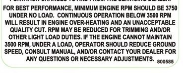
17 Set the mowing deck appropriately to achieve the desired height of your cut. The recommended cutting height is 2-3 inches (5-7 cm), though your preference may be a higher or lower cut. Tall grass or weeds should be cut with the mower deck set to its highest position. The fi rst time you mow, set the cut height slightly higher than normal, then adjust accordingly. 1. Refer to the deck height indicator decal adjacent to the deck height pedal. 2. Determine the appropriate setting for your desired cut height, starting with the highest. 3. Adjust the setting by applying slight pressure to the pedal handle towards the middle of the mower and then raising or lowering the pedal. Ensure the stop in the lever settles into the appropriate notch in the rail. Operation Setting the Cutting Height Mowing Speed The mower is designed to operate most effi ciently at maximum blade speed (engine 3600 rpm). The speed of the mower should allow the mower deck blades to maintain this maximum speed while mowing across turf. Control the ground speed with speed control levers. Slow the mower for cutting tall grass, grass that is heavy with moisture, or when moving uphill. If ground speed is too fast or blade speed is too slow, mowing will be uneven because the mower blades will not be able to lift grass into cutting position as the mower passes over the ground. Fuel level Indicator Handle fuel with care. Use only WA N N approved fuel containers. Never add fuel while the engine is running or hot. Fill fuel tank outdoors, never indoors. Replace the fuel tank cap securely and wipe up all spilled fuel. Failure to comply may result in damage to the equipment and/or injury to persons. Deck Height Setting Indicator *Each hole is approximately 1/2 change in cut height. The fender on the trim side of the mower has a cut out in the stainless steel allowing for easy fuel level assessment. Deck Height Adjustment Pedal Fuel Level Indicator
18 Operation To Mow NOTE: Always set engine speed at full- throttle when mowing. This engine speed will provide the necessary airflow to the engine cowling to prevent overheating and will maintain blade speed for a satisfactory quality of cut. If the engine pulls below full throttle when under load, slow down the ground speed and allow the engine to recover to full throttle. Slow the mower for cutting tall grass or when mowing uphill. If ground speed is too fast or blade speed is too slow, mowing will be uneven because the mower blades will not be able to lift the grass into cutting position as the mower passes over the ground. 1. Set the mowing deck height to desired cut height 2. To release the parking brake, push the parking brake lever all the way down. 3. Set the throttle to full throttle position. 4. Engage the mower deck by pulling up on the deck engaging switch (PTO). 5. Set the throttle at the full-throttle position. 6. Steer and accelerate the mower using the steering speed control levers as explained in this manual. To Tow NOTE: Do not exceed a speed of 2 mph when moving the mower without power. In order to transport the mower without power, you must fi rst release the hydraulic pressure by using the bypass lever located on each transaxle. Gain access to the bypass levers under the main chassis, behind the rear wheels. The levers are held in the front locking notch under spring pressure. Pull the lever toward the back of the mower until detent is felt in handle, enabling the mower to be moved without power. Under rear of mower, looking forward Mower Shutdown Procedure NOTE: Engine may be stopped at any time by turning the ignition key to the OFF position. 1. Move the steering speed control levers to neutral position to stop mower movement. 2. Push the deck engaging switch (PTO) down to disengage mower deck blades. 3. Pull the parking brake lever all the way up. 4. Move the throttle to the idle position. 5. Allow the engine to idle for two minutes. 6. Turn the ignition key to the OFF position and remove the key, even if leaving the mower unattended for only a few minutes. Bypass Lever (1 per transaxle, 2 total)
19 Basic Mower Adjustments, Maintenance, and Repair Blade Replacement NEVER work with mower blades AUT ON while mower is running. Make sure that ignition switch is off, key is removed, PTO switch is disengaged, steering speed control levers are in neutral lock, and parking brake is on. Failure to comply can result in personal injury or death. While setting up, repairing, or A N N transporting your mower, disconnect the negative battery terminal. Failure to comply can result in personal injury or death. A N Use caution when handling mower blades during replacement or maintenance. Wear appropriate protective gloves and clothing. Cover the sharp cutting edges of the blades. Failure to comply can result in personal injury. 1. Chock rear tires. 2. Lift front end of mower and support it with a jack or jack stands that have sufficient safe working load capacities. 3. Wedge a short piece of lumber between the mower blade and the mower deck to immobilize the blade while removing and reattaching hardware. 4. Remove bolts and washers attaching blade to blade spindle shafts, before removing blades. 5. Apply anti-seize compound to threads of attaching bolts before installation of new or sharpened blades. 6. In reverse order as removed, install new or sharpened blade with spacer, washers, and bolts. Make certain to keep the lift area (turned-up section of the blade) facing the underside of mower deck. Ensure that the fiber washer (which acts as a vibration damper) is against the blade. (Replace fiber washer if damaged or degraded) 7. Tighten bolts to a torque of ft-lbs. Under Deck Cleaning Do not clean the underside of AU N the deck with a pressure washer. Water can get in and under seals and cause damage to equipment. Clean the underside of the deck frequently. Accumulation of debris seriously impairs the mower s ability to lift the grass into cutting position and discharge the clippings evenly. Build up on the underside of the mower deck often results in a poor quality of cut. Battery Maintenance During off-season storage, use a trickle charger to maintain the battery. Prior to performing any and all WA N N maintenance, make sure that the ignition switch is off and key removed, PTO switch is disengaged, steering speed control levers are in neutral lock, and parking brake is on. Failure to comply may result in personal injury or death. Mower Cleaning & Off-Season Storage Clean and store the mower at the end of the mowing season as follows: 1. Perform steps as applicable under routine maintenance. 2. Remove all grass, dirt, and debris from the machine. Wash mower with an automotive type detergent. 3. Thoroughly apply grease to grease zerks as shown on page Check tires for proper inflation. 5. Start mower and engage PTO for approximately one minute to remove excess water from belts and pulleys

20 Basic Mower Adjustments, Maintenance, and Repair AU O Never attempt to make any adjustments to mower deck or work under it while mower is running. Make sure that ignition switch is off and key removed, PTO switch is disengaged, steering speed control levers are in neutral lock, and parking brake is on. Failure to comply will result in personal injury or death. Hour Meter Functions: 1. Tachometer 2. Engine Hours 3. System Voltage 4. Initial Oil Change (Break in oil) 5. Scheduled Oil Service Alert 6. Air fi lter service Alert 7. Fuel fi lter service Alert Drive Belt Replacement Replace the drive belts if they show signs of cuts, tears, burns caused by slipping, or excessive wear. Refer to the Routine Maintenance section of this manual for a schedule of replacement. 1. Loosen the tension on the vertical/ horizon tal idler pulley by pulling it away from belt. 2. Remove belt from pulley noting the routing of belt. 3. Install new belt onto pulley, routing it in the same confi guration as the replaced belt. The pulley can be moved as needed. See belt routing on page 19. Deck Drive Belt Tension (Non-Adjustable) Mode Button Operation: Push and release mode button to toggle between functions, the mode button will also be used to clear alerts and/or timers. The service alert timer counts down from a set interval,when the hour meter reaches the GENTLE ALERT INTERVAL for a qualifying function your meter will begin to fl ash messages such as CHG OIL, SVC AIR FILTER and SVC FUEL FILTER. As the interval countdown continues and 0 hours remain for service intervals messages such as CHG OIL NOW, SVC AIR FILTER NOW, SVC FUEL FILTER NOW will be displayed. Engine to Deck Idler Arm Reset Procedure: Select the alert or timer you would like to reset press and HOLD the mode button for 3 to 7 seconds (an alert or timer reset can be performed at any time)

21 Basic Mower Adjustments, Maintenance, and Repair Preparing the Mower for Storage Prepare the engine for storage at the end of the mowing season as follows: 1. Run engine for 15 minutes or longer. 2. Shut off engine. 3. Drain oil while engine is still warm 4. Remove engine oil fi lter. 5. Refi ll crankcase with fresh oil. Refer to engine owner s manual for proper oil type and viscosity. 6. Install new engine oil fi lter. 7. Run the engine until it runs out of gas and/ or use a fuel stabilizer. Gasoline forms harmful gum and varnish deposits in the carburetor and fuel system as it becomes old. Do not store gasoline for more A T ON than 2 months. Failure to comply can cause damage to equipment or personal injury. Tracking Adjustment Steering and tracking may need minor adjustments if the unit steers to the right or left when both steering control levers are pushed all the way forward. (Use caution before adjusting the steering and tracking on your mower. Several elements affect steering and tracking such as rough terrain and tire pressure.) 1. Determine the side of your drive system that has the fastest ground speed. i.e. (If your machine steers to the right your left side is faster than your right side.) 2. Adjusting the fastest side of your drive system to match the speed of your slower drive system component.(manufacturer Recommendation) 3. Adjust the tracking adjustment bolts clockwise to slow the machine down and counter clockwise to speed the machine up. Tracking Adjustment Bolts 8. Remove and replace fuel fi lter if needed. 9. Check oil fi ll and fuel tank caps to make sure they are securely in place. Preparation for New Mowing Season Prepare the stored mower for the new mowing season as follows: 1. Clean mower and remove any debris and dirt accumulation. 2. Check the engine oil levels. 3. Fill fuel tank with fresh gasoline. 4. Run the engine at half speed for 5 minutes and check the operation of the steering speed control levers. Then, stop engine and check for oil leaks, loose fi ttings, etc Ensure all safety devices are operational and review the general safety precautions listed in the front of this manual. 6. Check air pressure in tires. If needed, infl ate to proper pressure: front tires-15 psi and rear tires-10 psi. (See maintenance chart on page 8.)
22 Basic Mower Adjustments, Maintenance, and Repair Belt Routing 1.) Engine to Deck Belt 2.) Engine to Transmission Belt REAR 2 1 FRONT
23 Notes


24 6302 E. County Road 100 North Coatesville, Indiana Specifi cations and instructions subject to change without notice. Dixie Chopper and Magic Circle, are registered trademarks of Magic Circle Corporation any and all use and/or reproductions are strictly prohibited. Printed In USA REV
Parts and Owners Manual
 Parts and Owners Manual MOWER MODEL: SERIAL: ENGINE MODEL & HP: DATE PURCHASED: PURCHASED FROM: You must receive special training from the dealer before operating this mower. 9/30/2005 Commercial Mower
DRAG HARROW SAFETY & OPERATING INSTRUCTIONS. Original Language. Serial No. Order No.
 DR ` DRAG HARROW SAFETY & OPERATING INSTRUCTIONS Serial No. Order No. Original Language DR Power Equipment Toll-free phone: 1-800-DR-OWNER (376-9637) Fax: 1-802-877-1213 Website: www.drpower.com Read and
Serial Numbers Engine Model # Model # Serial # Engine Serial # Date Purchased. Engine Spec. # Iron Eagle Owner s Manual.
 Serial Numbers 8084019 and Higher Model # Serial # Engine Model # Engine Serial # Date Purchased Engine Spec. # 700127 Iron Eagle Owner s Manual March, 2008 About This Manual AUTHORIZED DEALER This owner
44in Side Discharge Mower for Wheel Horse XL 440H Lawn Tractors Model No Serial No and Up
 Form No. 5-8 in Side Discharge Mower for Wheel Horse XL 0H Lawn Tractors Model No. 790 Serial No. 5000000 and Up Operator s Manual Register your product at www.toro.com Original Instructions (EN) Contents
Grounds Equipment Operation Contest Guidelines
 Contest Guidelines The Grounds Equipment Operation contest includes the following: 1. General safety test (true/false and multiple choice)* covering: a. Walk behind power lawn mower. b. Gasoline powered
48 Mower Wheel Horse 5xi Garden Tractor Attachment
 Form No. 6-565 8 Mower Wheel Horse 5xi Garden Tractor Attachment Model No. 786 Serial No. 000000 and Up Model No. 786 Serial No. 000000 and Up Operator s Manual Domestic English (EN) Contents Page Introduction................................
44 Mower Wheel Horse 5xi Tractor Attachment
 Form No. -660 44 Mower Wheel Horse 5xi Tractor Attachment Model No. 7857 890000 and Up Model No. 7858 890000 and Up Operator s Manual Domestic English (EN) Introduction We want you to be completely satisfied
OPERATOR'S MANUAL. MODEL GC-F4 Fabric Grass Catcher P/N 9055 GRASS CATCHER GC-F4. PART Rev.2 SC301G
 OPERATOR'S MANUAL MODEL GC-F4 Fabric Grass Catcher P/N 9055 GRASS CATCHER GC-F4 1 2 8 11 10 9 5 6 7 4 3 SC301G PART 03213 Rev.2 SAFETY INSTRUCTIONS Your mower is only as safe as the operator! As with any
MICHIGAN FFA ZERO TURN MOWER SAFETY, MAINTENANCE & OPERATION - TEST BANK
 MICHIGAN FFA ZERO TURN MOWER SAFETY, MAINTENANCE & OPERATION - TEST BANK NOTE: These are examples of the type and subject of the questions you may see. They may appear re-worded or in another form at the
4-in-1 Professional Inflator Kit
 4-in-1 Professional Inflator Kit Owner s Manual WARNING: Read carefully and understand all ASSEMBLY AND OPERATION INSTRUCTIONS before operating. Failure to follow the safety rules and other basic safety
OPERATOR'S MANUAL GRASS CATCHER GC-4D
 OPERATOR'S MANUAL MODEL GC-4D Metal Grass Catcher P/N 9054 GRASS CATCHER GC-4D 5 1 7 10 11 13 14 6 8 9 3 2 7 4 SC300G PART 032 Rev.1 SAFETY INSTRUCTIONS Your mower is only as safe as the operator! As with
OPERATOR S MANUAL. Fabric Grass Catcher PART NO PRINTED 1/2011 PRINTED IN USA
 OPERATOR S MANUAL Fabric Grass Catcher Models: GC-F4 Congratulations on owning a Scag mower! This manual contains the operating instructions and safety information for your Scag mower accessory. Reading
All it takes is you. No gas, cords or batteries. StaySharp TM Max Reel Mower Model number:
 All it takes is you. No gas, cords or batteries StaySharp TM Max Reel Mower Model number: 362050 Before assembling or using the mower, read through the entire manual and fully understand the safety information.
60 FINISH CUT OWNER S MANUAL MODEL NO. T1360B1 T1360T T1360H T1360K T13560 RK1360 T Assembly Operation Service and Adjustment Repair Parts USA
 www.swisherinc.com OWNER S MANUAL MODEL NO. T1360B1 T1360T T1360H T1360K T13560 RK1360 T17560 60 FINISH CUT TRAILMOWER IMPORTANT Read and follow all Safety Precautions and Instructions before operating
SSFU SUPER SPRAYFAST UNIVERSAL ADHESIVE APPLICATOR
 S S F U SSFU SUPER SPRAYFAST UNIVERSAL ADHESIVE APPLICATOR MACHINERY DIVISION OWNER S MANUAL UNIT INSTRUCTIONS Please follow all SSFU Safety Instructions. Contact your Duro Dyne Tech Service if you have
Vac Bagger Wheelhorse 42 and 48 Mowers for Classic Garden Tractors
 Form No. -80 Vac Bagger Wheelhorse and 8 Mowers for Classic Garden Tractors Model No. 790 000000 & Up Operator s Manual Domestic English (EN) Contents Page Introduction................................
Zero Turning Radius Contest Guidelines
 Zero Turning Radius Contest Guidelines This contest will cover safety and procedures for operating a ZTR. The ZTR contest shall consist of the following: 1. General written safety test. 2. A skill contest
Bradley Stand-On Hydro Drive Mower Owner s Manual
 Bradley Stand-On Hydro Drive Mower Owner s Manual TABLE OF CONTENTS About This Manual... 3 Warranty... 4 Safety Information Before Using Equipment... 5 Operation of Equipment... 6 Safety Information Decals...
100C Air Compressor Kit
 10010 100C Air Compressor (standard mounting bracket, CE Spec) 10014 100C Air Compressor (no leader hose or check valve, CE Spec) 10016 100C Air Compressor (with Omega Bracket, CE Spec) IMPORTANT: It is
OWNERS MANUAL. Model Shown with optional Primary Mooring Cleats. Portable Mooring System SAFETY OPERATION MAINTENANCE PARTS
 OWNERS MANUAL Model 2400 Shown with optional Primary Mooring Cleats. Portable Mooring System SAFETY OPERATION MAINTENANCE PARTS CAUTION: Before using your new Pier Tender, read rules for Safety, Operation,
1000-Lb. Rapid Lift Hydraulic Table
 1000-Lb. Rapid Lift Hydraulic Table Owner s Manual WARNING: Read carefully and understand all ASSEMBLY AND OPERATION INSTRUCTIONS before operating. Failure to follow the safety rules and other basic safety
HAZARDS AND RISKS ASSOCIATED WITH THE USE OF RIDE ON MOWERS
 Safe Systems of Working Use of Ride on Mowers INTRODUCTION This Method Statement covers the safe working practices to be followed when using a ride on mower and should be used alongside the manufacturers
250C-IG COMPRESSOR KIT 12V PART NO C-IG COMPRESSOR KIT 24V PART NO
 250C-IG COMPRESSOR KIT 12V PART NO. 25050 250C-IG COMPRESSOR KIT 24V PART NO. 25058 IMPORTANT: It is essential that you and any other operator of this product read and understand the contents of this manual
OPERATOR S MANUAL. Striper. Models: SZL, SFZ, SFZP, SPZ, SCZ48/52 STRIPER STC, STCII, SCZ61/72, STT, STTII STRIPER
 OPERATOR S MANUAL Striper Models: SZL, SFZ, SFZP, SPZ, SCZ48/2 STRIPER STC, STCII, SCZ1/72, STT, STTII STRIPER This manual contains the operating instructions and safety information for your Scag mower
TABLE OF CONTENTS. INTRODUCTION to the AirVAC... 2 SAFETY INFORMATION... 3 DIMENSIONS & SPECIFICATIONS... 5 UNIT OVERVIEW... 6
 TABLE OF CONTENTS INTRODUCTION to the AirVAC... 2 SAFETY INFORMATION... 3 DIMENSIONS & SPECIFICATIONS... 5 UNIT OVERVIEW... 6 OPERATING PROCEDURE... 7 REPLACEMENT PARTS... 8 MAINTENANCE PROCEDURES... 11
IMPORTANT SAFETY INSTRUCTIONS
 IMPORTANT SAFETY INSTRUCTIONS CAUTION - To reduce risk of electrical shock: - Do not disassemble. Do not attempt repairs or modifications. Refer to qualified service agencies for all service and repairs.
250C-IG COMPRESSOR KIT 12V PART NO C-IG COMPRESSOR KIT 24V PART NO
 250C-IG COMPRESSOR KIT 12V PART NO. 25050 250C-IG COMPRESSOR KIT 24V PART NO. 25058 IMPORTANT: It is essential that you and any other operator of this product read and understand the contents of this manual
MODEL NUMBER: P-A AUTOMATIC PORTABLE COMPRESSOR
 MODEL NUMBER: 45043-450P-A AUTOMATIC PORTABLE COMPRESSOR IMPORTANT: It is essential that you and any other operator of the product read and understand the contents of this manual before installing and
444C DUAL PERFORMANCE VALUE PACK
 (Chrome) PART NO. 44432 IMPORTANT: It is essential that you and any other operator of this product read and understand the contents of this manual before installing and using this product. SAVE THIS MANUAL
400C & 450C DUAL PERFORMANCE VALUE PACKS
 (Chrome) PART NO. 40013 (Silver) PART NO. 45012 (Chrome) PART NO. 45013 IMPORTANT: It is essential that you and any other operator of this product read and understand the contents of this manual before
200 PSI COMPRESSORS - MODEL NUMBERS
 200 PSI COMPRESSORS - MODEL NUMBERS 380C AIR COMPRESSOR KIT PART NO. 38033 480C AIR COMPRESSOR KIT PART NO. 48043 380C 480C IMPORTANT: It is essential that you and any other operator of this product read
Pressure Relief Valve Instruction Manual
 CVR3-M0_062017 Pressure Relief Valve Instruction Manual MODEL: CVR3 SFA Companies 10939 N. Pomona Ave. Kansas City, MO 64153 Tel: 888-332-6419 * Fax: 816-448-2142 E-mail: sales@bvahydraulics.com Website:
450P AUTOMATIC PORTABLE COMPRESSOR EXTREME SERIES
 EXTREME SERIES PART NO. 45043 IMPORTANT: It is essential that you and any other operator of this product read and understand the contents of this manual before installing and using this product. SAVE THIS
Installation. 48in, 54in, or 60in Recycler Kit TimeCutter or TimeCutter HD Riding Mower WARNING. Loose Parts. Installation Instructions
 48in, 54in, or 60in Recycler Kit TimeCutter or TimeCutter HD Riding Mower Model No. 36-7488 Model No. 36-7489 Model No. 36-7490 Form No. 346-558 Rev A Installation Instructions WARNING CALIFORNIA Proposition
420C AIR COMPRESSOR KIT PART NO C AIR COMPRESSOR KIT PART NO
 420C AIR COMPRESSOR KIT PART NO. 42042 460C AIR COMPRESSOR KIT PART NO. 46043 420C 460C IMPORTANT: It is essential that you and any other operator of this product read and understand the contents of this
Installation Instructions Air Compressor Part # 2780, 2781
 Note: It is essential that the operator of this product read and understand the contents of this manual before installing and using this product. Parts Included Qty Parts Included Qty Compressor 1 Coil
1. SAFETY 2. PREPARATION 3. FRAME 4. TRANSMISSION 5. DRIVE 6. ROW UNIT 7. OPTIONAL EQUIPMENT
 TABLE OF CONTENTS 1. SAFETY 2. PREPARATION 3. FRAME 4. TRANSMISSION 5. DRIVE 6. ROW UNIT 7. OPTIONAL EQUIPMENT This symbol means: ATTENTION - BECOME ALERT YOUR SAFETY IS INVOLVED. When you see this symbol
OWNER S MANUAL. Sarlo BigMo 30 Hydro Walk-Behind. IMPORTANT: Date Purchased: Mower Model #: Mower Serial #: Engine Model #: Engine Serial #: Dealer:
 Sarlo BigMo 30 Hydro Walk-Behind OWNER S MANUAL IMPORTANT: Date Purchased: Mower Model #: Mower Serial #: Engine Model #: Engine Serial #: Dealer: CONGRATULATIONS on the purchase of your new Sarlo Mower.
INSTALLATION INSTRUCTIONS
 INSTALLATION INSTRUCTIONS Pattern Mowing Kit ST60119 02/11/2016 ENGLISH LP63764 Product Compatibility This kit is compatible with ZTrak Models with 48 in. or 54 in. Accel Deep TM (48A, 54A) mower decks
Parts & Operators Manual
 Parts & Operators Manual (888) 317-5878 www.talet.ca To The Owner General Comments Congratulations on the purchase of your new Talet Mat Grapple. Your unit was carefully designed and manufactured to give
Congratulations on your purchase of a JC Series Performer trike! The Performer JC Series is designed for everything from touring to commuting and
 Congratulations on your purchase of a JC Series Performer trike! The Performer JC Series is designed for everything from touring to commuting and shopping in the city. The JC Series frames are made of
MODEL NUMBER: P PORTABLE COMPRESSOR
 MODEL NUMBER: 30033-300P PORTABLE COMPRESSOR IMPORTANT: It is essential that you and any other operator of the product read and understand the contents of this manual before installing and using this product.
400H HARDMOUNT AIR COMPRESSOR KIT PART NO H HARDMOUNT AIR COMPRESSOR KIT PART NO
 400H HARDMOUNT AIR COMPRESSOR KIT PART NO. 40042 450H HARDMOUNT AIR COMPRESSOR KIT PART NO. 45042 400H 450H IMPORTANT: It is essential that you and any other operator of this product read and understand
AIR INLINE METAL SHEAR
 AIR INLINE METAL SHEAR ASSEMBLY and OPERATING INSTRUCTIONS 3491 Mission Oaks Blvd. / Camarillo, CA 93011 Copyright 1997 by Harbor Freight Tools. All rights reserved. No portion of this manual or any artwork
Model PSI Compressor with 3-Gallon Air Tank 12VDC
 Model 6350 150 PSI Compressor with 3-Gallon Air Tank 12VDC IMPORTANT: It is essential that you and any other operator of this product read and understandd the contents of this manual before installing
MODEL: HM381 COBRA LAWN MOWER OWNER S MANUAL
 MODEL: HM381 COBRA LAWN MOWER OWNER S MANUAL Cobra Garden Machinery Henton and Chattell Ltd., London Road, Nottingham NG2 3HW UK www.cobragarden.co.uk WARNING: For your own safety please read this manual
AC1810 / AC1810-A TECHNICAL SPECIFICATIONS. Operating Pressure psi ( kgs/cm²) [AC1810] Displacement. Net Weight
![AC1810 / AC1810-A TECHNICAL SPECIFICATIONS. Operating Pressure psi ( kgs/cm²) [AC1810] Displacement. Net Weight](/thumbs/83/88369739.jpg "AC1810 / AC1810-A TECHNICAL SPECIFICATIONS. Operating Pressure psi ( kgs/cm²) [AC1810] Displacement. Net Weight") Technical Specifications Operating Instructions Maintenance Information Troubleshooting Guide Parts Diagrams AC1810 / AC1810-A THE EVOLUTION OF PERFECTION CAUTION: Before attempting to use or service this
Technical Specifications Operating Instructions Maintenance Information Troubleshooting Guide Parts Diagrams AC1810 / AC1810-A THE EVOLUTION OF PERFECTION CAUTION: Before attempting to use or service this
INTENDED USE TECHNICAL SPECIFICATIONS
 1/2IN. HEAVY-DUTY AIR IMPACT WRENCH OWNER S MANUAL WARNING: Read carefully and understand all INSTRUCTIONS before operating. Failure to follow the safety rules and other basic safety precautions may result
450P- RV AUTOMATIC PORTABLE COMPRESSOR EXTREME SERIES
 450P- RV AUTOMATIC PORTABLE COMPRESSOR EXTREME SERIES PART NO. 45053 IMPORTANT: It is essential that you and any other operator of this product read and understand the contents of this manual before installing
HYDRAULIC WINCH FOR AUGERS UP TO WR10 X 71 / W130 X 41 ASSEMBLY & OPERATION MANUAL
 HYDRAULIC WINCH ASSEMBLY & OPERATION MANUAL Read this manual before using product. Failure to follow instructions and safety precautions can result in serious injury, death, or property damage. Keep manual
The installation of this kit must be performed by an authorized Honda riding mower dealer. These instructions are provided for dealer use.
 1. DEALER INSTALLATION INSTRUCTIONS The installation of this kit must be performed by an authorized Honda riding mower dealer. These instructions are provided for dealer use. FOLLOW THESE INSTRUCTIONS
MODEL NUMBER: P PORTABLE COMPRESSOR
 MODEL NUMBER: 44043-440P PORTABLE COMPRESSOR IMPORTANT: It is essential that you and any other operator of the product read and understand the contents of this manual before installing and using this product.
accidents which arise due to non-observance of these instructions and the safety information herein. SPECIFICATIONS
 18 GAUGE 1-1/4 INCH BRAD NAILER Model: 7611 CALIFORNIA PROPOSITION 65 WARNING: You can create dust when you cut, sand, drill or grind materials such as wood, paint, metal, concrete, cement, or other masonry.
97C COMPRESSOR KIT 12V PART NO C COMPRESSOR KIT 24V PART NO C COMPRESSOR KIT PART NO
 97C COMPRESSOR KIT 12V PART NO. 00097 97C COMPRESSOR KIT 24V PART NO. 02497 98C COMPRESSOR KIT PART NO. 00098 97C 98C IMPORTANT: It is essential that you and any other operator of this product read and
OPERATOR S MANUAL. Striper. Models: SZL/SFZ/SCZ48/52 STRIPER STC/SCZ/STT STRIPER Scag Power Equipment Division of Metalcraft of Mayville, Inc.
 OPERATOR S MANUAL Striper Models: SZL/SFZ/SCZ48/2 STRIPER STC/SCZ/STT STRIPER This manual contains the operating instructions and safety information for your Scag mower accessory. Reading this manual can
MODEL NUMBER: PSI AIR SOURCE KIT 200 PSI Compressor on 2.0 Gallon 200 PSI Air Tank
 IMPORTANT SAFETY INSTRUCTIONS CAUTION - To reduce risk of electrical shock or Electrocution: MODEL NUMBER: 20008 200 PSI AIR SOURCE KIT 200 PSI Compressor on 2.0 Gallon 200 PSI Air Tank IMPORTANT: It is
Belt Sander. Owner s Manual
 Belt Sander Owner s Manual WARNING: Read carefully and understand all ASSEMBLY AND OPERATION INSTRUCTIONS before operating. Failure to follow the safety rules and other basic safety precautions may result
Angled Sign Light with Shade
 Angled Sign Light with Shade Owner s Manual WARNING: Read carefully and understand all ASSEMBLY AND OPERATION INSTRUCTIONS before operating. Failure to follow the safety rules and other basic safety precautions
PC1131 Electric Air Compressor
 Senco Products Inc. 8485 Broadwell Road Cincinnati, Ohio 45244 PC1131 Electric Air Compressor Operating Instructions C US 2006, 2007 by Senco Products, Inc. Warnings for the safe use of this tool are included
Owner s. product. Failure injury
 100-Ft. Hose Reel Cart Owner s Manual WARNING: Read and understand all instructions, warnings, and cautions before using this product. Failure to follow the instructions, warnings, and cautions may result
AIR COMPRESSOR OPERATING INSTRUCTION AND PARTS LIST
 AIR COMPRESSOR OPERATING INSTRUCTION AND PARTS LIST OIL-LESS TYPE IMPORTANT: PLEASE READ CAREFULLY BEFORE STARTING OPERATIONS. THE CONTENTS ARE FOR GENERAL INFORMATION OF ALL THE SIMILAR MODELS. Record
MODEL NUMBER: M20005 AIR SOURCE KIT. 30% Duty Compressor on. 2.0 Gallon Air Tank SAVE THIS MANUAL FOR FUTURE REFERENCE
 MODEL NUMBER: M20005 AIR SOURCE KIT 30% Duty Compressor on 2.0 Gallon Air Tank SAVE THIS MANUAL FOR FUTURE REFERENCE USER MANUAL IMPORTANT SAFETY INSTRUCTIONS CAUTION - To reduce risk of electrical shock
2000 lb manual winch
 2000 lb manual winch Model 41694 Operation Instructions Due to continuing improvements, actual product may differ slightly from the product described herein. 3491 Mission Oaks Blvd., Camarillo, CA 93011
100 TOW BEHIND MOWER Owner s Manual
 100 TOW BEHIND MOWER Owner s Manual This manual contains important safety instructions for the gasoline engine powered tow behind mower model: READ SAFETY WARNINGS AND OPERATING INSTRUCTIONS CAREFULLY.
60 farm jack. Distributed exclusively by Harbor Freight Tools Mission Oaks Blvd., Camarillo, CA 93011
 60 farm jack 66183 Set up And Operating Instructions Distributed exclusively by Harbor Freight Tools. 3491 Mission Oaks Blvd., Camarillo, CA 93011 Visit our website at: http://www.harborfreight.com Read
accidents which arise due to non-observance of these instructions and the safety information herein. SPECIFICATIONS
 18 GAUGE 2 INCH BRAD NAILER Model: 7555 CALIFORNIA PROPOSITION 65 WARNING: You can create dust when you cut, sand, drill or grind materials such as wood, paint, metal, concrete, cement, or other masonry.
Thanks for shopping with Improvements! 20 Reel Mower with Catcher Item #
 Thanks for shopping with Improvements! 20 Reel Mower with Catcher Item # 411837 To order, call 1-800-642-2112 West Chester, OH 45069 0313 If you have any questions regarding this product, call 1-800-642-2112
60 Drum Style Spike Aerator
 60 Drum Style Spike Aerator OWNER S MANUAL WARNING: Read carefully and understand all ASSEMBLY AND OPERATION INSTRUCTIONS before operating. Failure to follow the safety rules and other basic safety precautions
Yoke Block Instruction Manual
 Yoke Block Instruction Manual ! WARNING IMPORTANT: READ MANUAL COMPLETELY BEFORE OPERATING THIS DEVICE This manual contains instructions on periodically required checks to be performed by the user. These
60 PRO FINISH CUT OWNER S MANUAL. With Assembly Instructions For Model: Pro60K KUNZ ENGINEERING, INC. / MENDOTA, IL / PH (815) /08
 /08") 60 PRO FINISH CUT OWNER S MANUAL With Assembly Instructions For Model: Pro60K KUNZ ENGINEERING, INC. / MENDOTA, IL 61342 / PH (815) 539-6954 1/08 ASSEMBLY INSTRUCTIONS READ THE COMPLETE ASSEMBLY INSTRUCTIONS
60 PRO FINISH CUT OWNER S MANUAL With Assembly Instructions For Model: Pro60K KUNZ ENGINEERING, INC. / MENDOTA, IL 61342 / PH (815) 539-6954 1/08 ASSEMBLY INSTRUCTIONS READ THE COMPLETE ASSEMBLY INSTRUCTIONS
S&S. Installation Instructions: S&S Stealth Air Cleaner Kit for Harley-Davidison Models With Stock Cable Operated Delphi EFI
 Instruction 510-0388 01-11-16 Version 1 Copyright 2016 by S&S Cycle, Inc. All rights reserved. Printed in the U.S.A. S&S Cycle, Inc. 14025 Cty Hwy G PO Box 215 Viola, Wisconsin 54664 Phone: 608-627-1497
Manual. FRESH AERO OneOP Model PC (Portable Compressors) Tire Inflator. Where Imagination Meets Innovation
 Tire Inflator. Where Imagination Meets Innovation") FRESH AERO OneOP Model PC (Portable Compressors) Tire Inflator For inflating aircraft tires and all types of other vehicle tires and air operated devices Manual The Fresh Aero Group Where Imagination Meets
FRESH AERO OneOP Model PC (Portable Compressors) Tire Inflator For inflating aircraft tires and all types of other vehicle tires and air operated devices Manual The Fresh Aero Group Where Imagination Meets
AIR COMPRESSOR. Failure to follow all instructions as listed below may result in electrical shock, fire, and/or serious personal injury.
 2 GALLON AIR COMPRESSOR Model: 7517 DO NOT RETURN TO STORE. Please CALL 800-348-5004 for parts and service. CALIFORNIA PROPOSITION 65 WARNING: You can create dust when you cut, sand, drill or grind materials
OPERATOR S MANUAL AND PARTS LISTING FOR THE. STM Mounted Harrow
 MANUFACTURERS OF QUALITY AGRICULTURAL EQUIPMENT SINCE 1936 OPERATOR S MANUAL AND PARTS LISTING FOR THE STM Mounted Harrow With FH 5-Bar Section VERSION: 10-07AJF TO THE OWNER AND OPERATORS Before assembling
For riders age 8 years and older OWNERS MANUAL AND RIDING INSTRUCTIONS
 For riders age 8 years and older OWNERS MANUAL AND RIDING INSTRUCTIONS CONTENTS MASTER ASSEMBLY HOW TO RIDE SAFETY TIPS MAINTENANCE page 3 page 4 & 5 page 6 page 7 AN IMPORTANT MESSAGE TO PARENTS: This
OPERATOR'S & PARTS MANUAL
 MULTI-TASK ATTACHMENT OPERATOR'S & PARTS MANUAL OM638 8963 11-5-04-3 REV. 3 75538 IMPORTANT: Read this manual carefully. It contains information about your safety and the safety of others. Also become
310 SERIES TILT-TO-LOAD ROTATOR. The Specialist In Drum Handling Equipment
 OPERATOR S MANUAL FOR MORSE TILT-TO-LOAD DRUM ROTATOR SAFETY INFORMATION: While Morse Manufacturing Co. drum handling equipment is engineered for safety and efficiency, a high degree of responsibility
G10K - 1/2" Heavy-Duty Air Impact Wrench
 G10K - 1/2" Heavy-Duty Air Impact Wrench OWNER S MANUAL WARNING: Read carefully and understand all ASSEMBLY AND OPERATION INSTRUCTIONS before operating. Failure to follow the safety rules and other basic
SPECIFICATIONS Type: Twin stack, single phase Tank: 4 gallon Air Output: PSI; PSI Max PSI: 125 PSI HP: 1.
 2 GALLON TWIN STACK AIR COMPRESSOR Model: 9526 DO NOT RETURN TO STORE. Please CALL 800-348-5004 for parts and service. CALIFORNIA PROPOSITION 65 WARNING: You can create dust when you cut, sand, drill or
42 inch Mower for TimeCutter Z Riding Mowers. Note: Determine the left and right sides of the machine from the normal operating position.
 Recycler Form No. -7 Kit inch Mower for TimeCutter Z Riding Mowers Model No. 798 Note: Determine the left and right sides of the machine from the normal operating position. Loose Parts Note: Use the chart
Foldable Magne c Exercise Bike
 ASSEMBLY INSTRUCTIONS Foldable Magne c Exercise Bike CAUTION! Please make sure the pedals are attached to the correct sides, L to left and R to right. Screw in the right pedal clockwise and the left counter-clockwise.
Heavy-Duty Hot Knife
 Heavy-Duty Hot Knife Owner s Manual WARNING: Read carefully and understand all ASSEMBLY AND OPERATION INSTRUCTIONS before operating. Failure to follow the safety rules and other basic safety precautions
DISASSEMBLING & REASSEMBLING CARTRIDGE INSTALLING SEATPOST ON BIKE
 INTRODUCTION BILL OF MATERIALS SPECIFICATIONS & TOOLS PROCEDURES DISASSEMBLING & REASSEMBLING CARTRIDGE INSTALLING SEATPOST ON BIKE OPERATION OF SEATPOST GIANT LIMITED WARRANTY 1 INTRODUCTION Congratulations
Tru Trak Sulky Proline Mid Size Mower Attachment
 Form No. -7 Tru Trak Sulky Proline Mid Size Mower Attachment Model No. 00 000000 and Up Operator s Manual Domestic English (EN) Contents Page Introduction................................ Safety.....................................
Cylinder Tilt Saddle Instruction Manual
 Cylinder Tilt Saddle Instruction Manual MODELS: SDT05, SDT10, SDT15, SDT25 SFA Companies 10939 N. Pomona Ave. Kansas City, MO 64153 Tel: 888-332-6419 - Fax: 816-448-2142 E-mail: sales@bvahydraulics.com
ORBITAL AIR SANDER. Owner s Manual
 ORBITAL AIR SANDER Owner s Manual WARNING: Read carefully and understand all ASSEMBLY AND OPERATION INSTRUCTIONS before operating. Failure to follow the safety rules and other basic safety precautions
BIKE TO GO - USER MANUAL - MODEL#: JBTG24
 BIKE TO GO 24 - USER MANUAL - MODEL#: JBTG24 GET ACQUAINTED WITH YOUR 24 BIKE TO GO Congratulations on your new Jetson 24 folding bicycle! The Jetson 24 Bike to Go is an innovative and fun personal transportation
SPECIFICATIONS TABLE Maximum Air Pressure 115 PSI Air Tank Capacity 20 Gallons
 SPECIFICATIONS TABLE Maximum Air Pressure 115 PSI Air Tank Capacity 20 Gallons Air Flow Capacity 6.2 CFM at 40 PSI 5.2 CFM at 90 PSI Motor 2.5 HP Working / 4 HP Peak 120 Volt / 60 Hz / 13 A / 1-Phase Required
FRESH AERO OneOP Model RC (Reservoir/tank) Tire Inflating System
 Tire Inflating System") FRESH AERO OneOP Model RC (Reservoir/tank) Tire Inflating System For inflating aircraft tires and all types of other vehicle tires and air operated devices Manual The Steelebrook Group Where Imagination
FRESH AERO OneOP Model RC (Reservoir/tank) Tire Inflating System For inflating aircraft tires and all types of other vehicle tires and air operated devices Manual The Steelebrook Group Where Imagination
480C DUAL PERFORMANCE VALUE PACK
 (Pewter) PART NO. 48012 (Chrome) PART NO. 48032 (Stealth Black) PART NO. 48042 IMPORTANT: It is essential that you and any other operator of this product read and understand the contents of this manual
WARNING: FOR OUTDOOR USE ONLY
 Certified to CSA International 4.96 US For Outdoor Gas Fireplaces A HIGHER STANDARD IN QUALITY AND APPEARANCE SAFE AND BEAUTIFUL OUTDOOR LARGO FIRE PIT FOR PROPANE AND *NATURAL GAS OWNER S MANUAL WARNING:
CastCreations PRODUCT DESCRIPTION. Redwood Stump Fire Pit Item #: C1002. CastCreations Ph: Aurora, Utah
 CastCreations PRODUCT DESCRIPTION Redwood Stump Fire Pit Item #: C1002 Manufactured by: Questions or Concerns? CastCreations Ph: 1-435-529-3350 PO Box 155 E-mail: info@ccfandw.com Aurora, Utah UNIT COMPONENTS
HEAVY-DUTY AIR RATCHET WRENCH OWNER S MANUAL
 HEAVY-DUTY AIR RATCHET WRENCH OWNER S MANUAL WARNING: Read carefully and understand all INSTRUCTIONS before operating. Failure to follow the safety rules and other basic safety precautions may result in
TrekMill USER'S MANUAL MM5050
 Read the safety and comfort guide in this manual before using this equipment. USER'S MANUAL TrekMill MM5050 Serial Number: Date Purchased: Find the serial number in the location shown below. CONTENTS Safety
ATD /8 x 50 Retractable Air Hose Reel Owner s Manual
 ATD-31166 3/8 x 50 Retractable Air Hose Reel Owner s Manual Features Heavy-gauge, all-steel reel assembly 8-position ratchet mechanism locks reel at desired hose length 5-position adjustable roller outlet
AIR HYDRAULIC RIVETER
 AIR HYDRAULIC RIVETER Owner s Manual WARNING: Read carefully and understand all ASSEMBLY AND OPERATION INSTRUCTIONS before operating. Failure to follow the safety rules and other basic safety precautions
12 Inch Barn Light. Owner s Manual
 12 Inch Barn Light Owner s Manual WARNING: Read carefully and understand all ASSEMBLY AND OPERATION INSTRUCTIONS before operating. Failure to follow the safety rules and other basic safety precautions
Copyright Trek Bicycle Corporation 2005 All rights reserved
 i ii iii Aero Brake Levers Owner s Manual Table of contents Read this manual before you ride... 1 Introduction... 2 Inspect your brake levers regularly... 2 Adjusting aero brake levers... 2 Lubricating
Model ASSEMBLY and OPERATING INSTRUCTIONS
 QUICK CHANGE AIR BRUSH KIT Model 93506 ASSEMBLY and OPERATING INSTRUCTIONS Due to continuing improvements, actual product may differ slightly from the product described herein. 3491 Mission Oaks Blvd.,
200 PSI FAST-FILL AIR SOURCE KIT
 200 PSI FAST-FILL AIR SOURCE KIT 55% Duty Compressor on 2.0 Gallon Air Tank PART NO. 20007 IMPORTANT: It is essential that you and any other operator of this product read and understand the contents of