Instructions for the following series products: ExoFit Full Body Harnesses (See back pages for specific model numbers.)
|
|
|
- Abel Reynolds
- 5 years ago
- Views:
Transcription
 This manual is intended to meet the Manufacturer s Instructions as required by CSA Z259.")
1 Instructions for the following series products: ExoFit Full Body Harnesses (See back pages for specific model numbers.) This manual is intended to meet the Manufacturer s Instructions as required by CSA Z and ANSI Z359 and should be used as part of an employee training program as required by OSHA. Form: Rev: E Copyright 2011, DB Industries, Inc.
2
3 WARNING: This product is part of a personal restraint, work positioning, suspension, or rescue system. These instructions must be provided to the user and rescuer (see section 8.0 Terminology). The user must read and understand these instructions or have them explained to them before using this equipment. The user must read and follow the manufacturer s instructions for each component or part of the complete system. Manufacturer s instructions must be followed for proper use and maintenance of this product. Alterations or misuse of this product or failure to follow instructions may result in serious injury or death. IMPORTANT: If you have questions on the use, care, or suitability of this equipment for your application, contact DBI-SALA. IMPORTANT: Before using this equipment, record the product identification information from the ID label into the inspection and maintenance log in section 10.0 of this manual. DESCRIPTIONS ExoFit Vest Style Full Body Harness: See Figure 1. ExoFit Cross-Over Style Full Body Harness: See Figure 2. OPTIONS: DBI-SALA ExoFit and ExoFit XP Full Body Harnesses are available with options and accessories. Following is a partial list of commonly used options and accessories (some options may not be available on all harnesses): Side D-rings Front D-rings Hip pad with side D-rings Tongue buckle body belt Lanyard attached directly to D-ring or attachment element 3
4 Figure 1 - ExoFit Vest Style Full Body Harness Shoulder Strap Quick Connect Buckle Chest Strap Parachute Buckle Quick Connect Buckle Leg Strap Dorsal D-ring Product Warning and Identification Labels 4
 Quick Connect Buckle Leg Strap Dorsal D-ring Product Warning and Identification Labels Side")
5 Figure 2 - ExoFit Cross-Over Style Full Body Harness Shoulder Strap Parachute Buckle Front Attachment Element (D-ring Or Web Loop) Quick Connect Buckle Leg Strap Dorsal D-ring Product Warning and Identification Labels Side D-rings 5
6 1.0 APPLICATIONS 1.1 PURPOSE: DBI-SALA ExoFit and ExoFit XP full body harnesses are to be used as components in personal fall arrest, restraint, work positioning, climbing, or rescue systems. See Figures 1 and 2 for harness styles. Harnesses included in this manual are full body harnesses and meet CSA Z259.10, ANSI Z359.1, and OSHA requirements. See Figure 3 for application illustrations. WARNING: Working at height has inherent risks. Some risks are noted here but are not limited to the following: falling, suspension/ prolonged suspension, striking objects, and unconsciousness. In the event of a fall arrest and/or subsequent rescue (emergency) situation, some personal medical conditions may affect your safety. Medical conditions identified as risky for this type of activity include but are not limited to the following: heart disease, high blood pressure, vertigo, epilepsy, drug or alcohol dependence, psychiatric illness, impaired limb function and balance issues. We recommend that your employer/ physician determine if you are fit to handle normal and emergency use of this equipment. A. PERSONAL FALL ARREST: The full body harness is used as a component of a personal fall arrest system. Personal fall arrest systems typically include a full body harness and a connecting subsystem (energy absorbing lanyard). Maximum arresting force must not exceed 1,800 lbs (8 kn).for fall protection applications connect the fall arrest subsystem (example: lanyard, SRL, energy absorber, etc.) to the D-ring or attachment element on your back, between your shoulder blades. B. WORK POSITIONING: The full body harness is used as a component of a work positioning system to support the user at a work position. Work positioning systems typically include a full body harness, positioning lanyard, and a back-up personal fall arrest system. For work positioning applications, connect the work positioning subsystem (example: lanyard, Y-lanyard, etc.) to the lower (hip level) side or belt mounted work positioning attachment anchorage elements (D-rings). Never use these connection points for fall arrest. C. LADDER CLIMBING: The full body harness is used as a component of a climbing system to prevent the user from falling when climbing a ladder or other climbing structure. Climbing systems typically include a full body harness, 6
7 Anchorage Connecting Subsystem (Self Retracting Lifeline Shown) Figure 3 - Applications Anchorage Connector Anchorage Anchorage Connector Restraint Lanyard Full Body Harness Full Body Harness Fall Arrest Restraint Anchorage Back-up Fall Arrest System Full Body Harness Anchorage Connector Restraint Lanyard Anchorage Connector Anchorage Cross-over Full Body Harness Ladder Cable Sleeve Cable Work Positioning Ladder Climbing vertical cable or rail attached to the structure, and climbing sleeve.for ladder climbing applications, harnesses equipped with a frontal D-ring in the sternal location may be used for fall arrest on fixed ladder climbing systems. These are defined in Z in Canada and ANSI A14.3 in the United States. D. RESCUE: The full body harness is used as a component of a rescue system. Rescue systems are configured depending on the type of rescue. For limited access (confined space) applications, harnesses equipped with D-rings on the shoulders may be used for entry and egress into confined spaces where worker profile is an issue. E. CONTROLLED DESCENT: For controlled descent applications, harnesses equipped with a single sternal level D-ring, one or two frontal mounted D-rings, or a pair of connectors originating below the waist (such as a seat sling) may be used for connection to a descender or evacuation system (reference Z259.1 in Canada). E. RESTRAINT: The full body harness is used as a component of a restraint system to prevent the user from reaching a fall hazard. Restraint systems typically include a full body harness and a lanyard or restraint line. 1.2 LIMITATIONS: Consider the following application limitations before using this equipment: 7
8 A. CAPACITY: These full body harnesses are designed for use by persons with a combined weight (clothing, tools, etc.) of no more than 352 lbs. (160 kg) Make sure all of the components in your system are rated to a capacity appropriate to your application. B. FREE FALL: Personal fall arrest systems used with this equipment must be rigged to limit the free fall to 6 feet (ANSI Z359.1). Restraint systems must be rigged so that no vertical free fall is possible. Work positioning systems must be rigged so that free fall is limited to 2 feet (.6 m) or less. Personnel riding systems must be rigged so that no vertical free fall is possible. Climbing systems must be rigged so that free fall is limited to 18 inches (.5 m) or less. Rescue systems must be rigged so that no vertical free fall is possible. See subsystem manufacturer s instructions for more information. C. FALL CLEARANCE: See Figure 4. There must be sufficient clearance below the user to arrest a fall before the user strikes the ground or other obstruction. The clearance required is dependent on the following factors: Elevation of anchorage Connecting subsystem length Deceleration distance Worker height Free fall distance Movement of harness attachment element Figure 4 illustrates Fall Clearance for a lanyard subsystem. For other subsystems, consult the manufacturer s product instructions. Figure 4 - Fall Clearance (Lanyards) RD = LL + DD + HH + C RD LL DD HH Required Fall Clearance Distance Length of Lanyard (Specified on labeling) Deceleration Distance = 4 ft (1.2 m) except: for ANSI/OSHA Lanyards with Free Fall greater than 6 ft (1.8 m) up to 12 ft (3.7 m), or user weights greater than 310 lbs (141 kg) up to 420 lbs (191 kg); add 1 ft (0.3 m): DD = 5 ft (1.5 m) for CSA E6 Lanyards, add 1.7 ft. (0.5 m): DD = 5.7 ft (1.7 m) Height of Suspended Worker RD LL DD C Safety Factor = 1.5 ft (0.5 m) (Factors in D-Ring Slide and Harness Stretch.) Example: Assuming a 6 ft (1.8 m) tall user with a typical 6 ft (1.8 m) lanyard with 6 ft (1.8 m) Free Fall, Fall Clearance calculation would be as follows: RD = LL + DD + HH + C RD = 6 ft + 4 ft + 6 ft ft = 17.5 ft RD = 1.8 m m m m = 5.3 m HH C 8
9 D. SWING FALLS: See Figure 5. Swing falls occur when the anchorage point is not directly above the point where a fall occurs. The force of striking an object in a swing fall may cause serious injury or death. Minimize swing falls by working as close to the anchorage point as possible. Do not permit a swing fall if injury could occur. Swing falls will significantly increase the clearance required when a self retracting lifeline or other variable length connecting subsystem is used. Figure 5 - Swing Fall Swing Fall Hazard E. EXTENDED SUSPENSION: A full body harness is not intended for use in extended suspension applications. If the user is going to be suspended for an extended length of time it is recommended that some form of seat support be used. DBI-SALA recommends a seat board, suspension work seat, seat sling, or a boatswain chair. Contact DBI-SALA for more information on these items. F. ENVIRONMENTAL HAZARDS: Use of this equipment in areas with environmental hazards may require additional precautions to prevent injury to the user or damage to the equipment. Hazards may include, but are not limited to; heat, chemicals, corrosive environments, high voltage power lines, gases, moving machinery, and sharp edges. G. TRAINING: This equipment must be installed and used by persons trained in its correct application and use. See section 4.0. IMPORTANT: When working with tools, materials, or in high temperature environments, ensure that associated fall protection equipment can withstand high temperatures, or provide protection for those items. 1.3 Refer to national Standards including ANSI Z359 (.0,.1,.2,.3, and.4) family of standards on fall protection, ANSI A10.32, CSA Z259.10, and applicable local, state and federal (OSHA) requirements governing occupational safety for more information about work positioning systems. 2.0 SYSTEM REQUIREMENTS 2.1 COMPATIBILITY OF COMPONENTS: DBI-SALA equipment is designed for use with DBI-SALA approved components and subsystems only. Substitutions or replacements made with non-approved components or subsystems may jeopardize compatibility of equipment and may effect the safety and reliability of the complete system. 9
10 2.2 COMPATIBILITY OF CONNECTORS: Connectors are considered to be compatible with connecting elements when they have been designed to work together in such a way that their sizes and shapes do not cause their gate mechanisms to inadvertently open regardless of how they become oriented. Contact DBI-SALA if you have any questions about compatibility. Connectors (hooks, carabiners, and D-rings) must be capable of supporting at least 5,000 lbs. (22.2kN). Connectors must be compatible with the anchorage or other system components. Do not use equipment that is not compatible. Non-compatible connectors may unintentionally disengage. See Figure 6. Connectors must be compatible in size, shape, and strength. Self locking snap hooks and carabiners are required by ANSI Z359.1 and OSHA. 2.3 MAKING CONNECTIONS: Only self-locking snap hooks and/or carabiners shall be used with this equipment. Ensure all connectors are fully closed and locked and compatible. DBI-SALA connectors (snap hooks and carabiners) are designed to be used only as specified in each product s user instructions. See Figure 3 for inappropriate connections. DBI-SALA snap hooks and carabiners should not be connected: A. To a D-ring which another connector is already attached. B. In a manner that would result in a load on the gate. Figure 6 - Unintentional Disengagement (Roll-out) If the connecting element that a snap hook (shown) or carabiner attaches to is undersized or irregular in shape, a situation could occur where the connecting element applies a force to the gate of the snap hook or carabiner. This force may cause the gate (of either a self-locking or a non-locking snap hook) to open, allowing the snap hook or carabiner to disengage from the connecting point. For ANSI Z compliant hooks, there are no restrictions on the size or shape of the mating connector provided the snap hook is free to align with the applied load as intended. Small ring or other non-compatibility connector 1. Force is applied to the snap hook. 2. The gate presses against the connecting ring. 3. The gate opens allowing the snap hook to slip off. 10
11 Figure 7 - Inappropriate Connections NOTE: Large throat snap hooks should not be connected to standard size D-rings or similar objects which will result in a load on the gate if the hook or D-ring twists or rotates, unless the snap hook complies with ANSI Z and is equipped with a 3,600 lb gate. Check the marking on your snap hook to verify that it is appropriate for your application. C. In a false engagement, where features that protrude from the snap hook or carabiner catch on the D-ring, and without visual confirmation seems to be fully engaged to the anchor point. D. To each other. E. Directly to webbing or rope lanyard for tie-back (unless specifically provided by the manufacturer). F. To any object which is shaped or dimensioned such that the snap hook or carabiner will not close and lock, or where rollout could occur. OTHER RESTRICTIONS: Do not make connections where the hook locking mechanism can come into contact with a structural member or other equipment and potentially release the hook. Do not connect a snap hook into a loop or thimble of a wire rope or attach in any way to a slack wire rope. The snap hook must be free to align with the applied load as intended (regardless of the size or shape of the mating connector). A caribiner may be used to connect to a single or pair of soft loops on a body support such as a body belt or full body harness, provided the carabiner can fully close and lock. This type of connection is not allowed for snap hooks. 11
12 A carabiner may be connected to a loop or ring connector that is already occupied by a choker style connector. This type of connection is not allowed for snap hooks. 2.4 CONNECTING SUBSYSTEMS: Connecting subsystems (selfretracting lifeline, lanyard, rope grab and lifeline, cable sleeve) must be suitable for your application. See section 1.1. See subsystem manufacturer s instructions for more information. Some harness models have web loop connection points. Do not use snap hooks to connect to web loops. Use a self-locking carabiner to connect to a web loop. Ensure the carabiner cannot crossgate load (load against the gate rather than along the backbone of the carabiner). Some lanyards are designed to choke onto a web loop to provide a compatible connection. See Figure 8. Lanyards may be sewn directly to the web loop forming a permanent connection. Do not make multiple connections onto one web loop, unless choking two lanyards onto a properly sized web loop. Figure 8 - Web Loop Connection Insert lanyard web loop through web loop or D-ring on harness 2.5 ANCHORAGE STRENGTH: The anchorage strength required is dependent on the application type. The following are the requirements of ANSI for these application types: A. FALL ARREST: Anchorages selected for fall arrest systems shall have a strength capable of sustaining static loads applied in the directions permitted by the system of at least: 1. 5,000 lbs. (22.2 kn) for non-certified anchorages, or 2. Two times the maximum arresting force for certified anchorages. When more than one fall arrest system is attached to an anchorage, the strengths set forth in (1) and (2) above shall be multiplied by the number of systems attached to the anchorage. B. RESTRAINT: Anchorages selected for restraint and travel restraint systems shall have a strength capable of sustaining static loads applied in the directions permitted by the system of at least: 1. 1,000 lbs. (4.5 kn) for non-certified anchorages, or 2. Two times the foreseeable force for certified anchorages. When more than one restraint and travel restraint system is attached to an anchorage, the strengths set forth in (1) and (2) above shall be multiplied by the number of systems attached to the anchorage. 12 Harness Web Loop or D-ring Web Loop on Energy Absorbing Lanyard Insert opposite end of lanyard through the lanyard web loop Pull the lanyard through the connecting web loop to secure
13 C. WORKING POSITIONING: Anchorages selected for work positioning systems shall have a strength capable of sustaining static loads applied in the directions permitted by the system of at least: 1. 3,000 lbs. (13.3 kn) for non-certified anchorages, or 2. Two times the foreseeable force for certified anchorages. When more than one work positioning system is attached to an anchorage, the strengths set forth in (1) and (2) above shall be multiplied by the number of systems attached to the anchorage. D. RESCUE: Anchorages selected for rescue systems shall have a strength capable of sustaining static loads applied in the directions permitted by the system of at least: 1. 3,000 lbs. (13.3 kn) for non-certified anchorages, or 2. Five times the foreseeable force for certified anchorages. When more than one rescue system is attached to an anchorage, the strengths set forth in (1) and (2) above shall be multiplied by the number of systems attached to the anchorage. E. CLIMBING: The structure to which a climbing system is attached must sustain the loads required by that particular system. See instructions for climbing system for requirements. 3.0 DONNING AND USE WARNING: Do not alter or intentionally misuse this equipment. Consult DBI-SALA when using this equipment in combination with components or subsystems other than those described in this manual. Some subsystem and component combinations may interfere with the operation of this equipment. Use caution when using this equipment around moving machinery, electrical and chemical hazards, and sharp edges. Figure 9 - Front and Back View of ExoFit Vest Style Full Body Harness Belt Loops Front Back 13
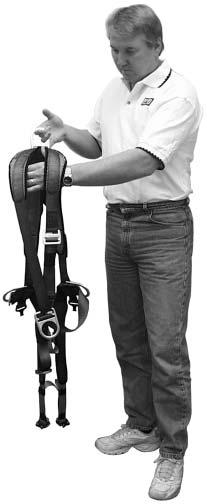
14 3.1 BEFORE EACH USE of this equipment inspect it according to section 5.0 of this manual. 3.2 PLAN your system before use. Consider all factors that will affect your safety during use of this equipment. The following list gives important points to consider when planning your system: A. ANCHORAGE: Select an anchorage that meets the requirements specified in sections 1.2 and 2.5. B. SHARP EDGES: Avoid working where system components may be in contact with, come in contact with, or abrade against, unprotected sharp edges. C. AFTER A FALL: Any equipment which has been subjected to the forces of arresting a fall or exhibits damage consistent with the effect of fall arrest forces as described in section 5.0, must be removed from service immediately and destroyed by the user, the rescuer, or an authorized person. D. RESCUE: The employer must have a rescue plan when using this equipment. The employer must have the ability to perform a rescue quickly and safely. 3.3 DONNING AND FITTING THE HARNESS: A. ExoFit Vest Style Full Body Harness: See Figure 9 for front and back views of the ExoFit Vest style full body harness. Your harness incorporates loops for a removable waist belt. The belt can be installed through the two loops in the harness located in the lower back shoulder straps. The belt will pass through the harness just below the padded area. The hip pad, if used, is secured to the belt by passing the belt through the hip pad loops. Don the ExoFit Vest style full body harness by following these steps (see Figures 10 and 11): Step 1. Step 2. Step 3. Locate back D-ring held in position by the D-ring pad; lift up harness and hold by this D-ring. Ensure the straps are not twisted. Grasp the shoulder straps and slip the harness onto one arm. The D-ring will be located on your back side. Ensure that the straps are not tangled and hang freely. Slip your free arm into the harness and position the shoulder straps on top of your shoulder. Ensure that the straps are not tangled and hang freely. The chest strap, with quick connect buckle, will be positioned on the front side when worn properly. Reach between your legs and grasp the gray leg strap on your left side. Bring the strap up between your legs and connect it by inserting the tab of the buckle into 14


15 Figure 10 - Donning ExoFit Vest Style Full Body Harness Step 1 Step 2 Step 3 Step 3 Step 4 Step 5 15


16 Figure 11 - ExoFit Quick Connect Buckle Connections Chest Strap: Attach chest strap by inserting the tab of the buckle into the receptor of the quick connect buckle until a click is heard Leg Straps: Attach leg strap by inserting the tab of the buckle into the receptor of the quick connect buckle until a click is heard receptor of quick connect buckle on the left side as shown in Figure 10. You will hear a click when the tab engages properly. Connect the right leg strap using the same procedure. Pull the free end of the strap away from the buckle to make a snug fit on each leg strap. To loosen the leg strap, grasp the yellow plastic portion of the buckle and pull away from your leg to allow the strap to pull through the buckle. A plastic end keeper on the end of the strap will stop it from pulling completely out of the buckle. To release the buckle, press the silver-colored tabs on the buckle towards each other with one hand, while pulling on the tab portion of the buckle with the other hand. Step 4. Attach the chest strap by inserting the tab of the buckle into the receptor of the quick connect buckle. You will hear a click when the tab engages properly. The chest strap should be 6 in. (15 cm) down from the top of your shoulders. Pass excess strap through the loop keepers. The strap may be tightened to a snug fit by pulling the free strap end to the left Figure 12 - ExoFit Cross-Over Style (away from the buckle). To loosen the chest strap, grasp the yellow plastic portion of the buckle and pull away from the body to allow the strap to pull Belt Loops through the buckle. A plastic end keeper on the end of the strap will stop it from pulling completely out of the buckle. To release the buckle, press the silver-colored tabs on the buckle toward each other with one hand, while pulling on the tab portion of the buckle with the other hand. 16


17 Figure 13 - Donning ExoFit Cross-Over Style Full Body Harness Step 1 Step 2 Step 3 Step 4 Step 5 17
 down from shoulder.")
18 Step 5. Adjust shoulder straps to a snug fit by pulling excess strap through the parachute buckles on each side of the harness. Left and right sides of shoulder straps should be adjusted to the same length and the chest strap should be centered on your lower chest, 6 in. (15 cm) down from shoulder. The front D-ring on the vest style harness is moved up or down by adjusting the shoulder straps and leg straps. Center the back D-ring between your shoulder blades. Note: On ExoFit XP models, the back (dorsal) D-ring can be repositioned up or down as needed for a correct fit. Adjust leg straps to a snug fit. At least 3 in. (8 cm) of webbing must extend past the buckle on the leg straps. Adjust the waist belt (if present). B. EXOFIT CROSS-OVER STYLE FULL BODY HARNESS: Your harness incorporates loops for a removable waist belt. The belt can be installed through the two loops in the harness located in the lower back shoulder straps, see Figure 12. The belt will pass through the harness just below the padded area. The hip pad, if used, is secured to the belt by passing the belt through the hip pad loops. Don the ExoFit Cross-Over style full body harness by following these steps (see Figures 13 and 14): Step 1. Step 2. Locate the back D-ring held in position by the D-ring pad; lift up the harness and hold by this D-ring. Ensure the straps are not twisted. Grasp the shoulder straps between the back and front D-ring and slip the harness over your head from the left side. Position the shoulder straps on top of your shoulders. Ensure that the straps are not tangled and hang freely. The D-ring will be positioned on your back when worn properly. Step 3. Grasp the tab of the buckle located at your right hip and insert it into the receptor of the quick connect buckle, see Figure 13. You will hear a click when the tab engages properly. Figure 14 - ExoFit Quick Connect Buckle Connections Hip Strap: Attach chest strap by inserting the tab of the buckle into the receptor of the quick connect buckle until a click is heard Leg Straps: Attach leg strap by inserting the tab of the buckle into the receptor of the quick connect buckle until a click is heard 18
19 Step 4. Step 5. Reach between your legs and grasp the gray leg strap on your left side. Bring the strap up between your legs and insert the tab of the buckle into the receptor of the buckle on the left side as shown in Figure 13. You will hear a click when the tab engages properly. Connect the right leg strap using the same procedure. Pull the free end of the strap away from the buckle to make a snug fit on each leg strap. To loosen the leg strap, grasp the yellow plastic portion of the buckle and pull away from your leg to allow the strap to pull through the buckle. A plastic end keeper on the end of the strap will stop it from pulling completely out of the buckle. To release the buckle, press the silver-colored tabs on the buckle towards each other with one hand, while pulling on the tab portion of the buckle with the other hand. Adjust shoulder strap to a snug fit by pulling excess strap through the parachute buckle. Left and right sides of the shoulder straps should be adjusted to the same length and the front D-ring should be centered on your lower chest. The back D-ring should be centered between your shoulder blades. Note: On ExoFit XP models, the back (dorsal) D-ring can be repositioned up or down as needed for a correct fit. Adjust the leg straps to a snug fit. At least 3 in. (8 cm) of webbing must extend past the buckle on the leg straps. Adjust the waist belt (if present). 3.4 USE OF FALL ARREST D-RING OR ATTACHMENT ELEMENT: For fall protection applications connect to the D-ring or attachment element on your back, between your shoulder blades. Side D-rings, if present, are for positioning or restraint applications only. Front D-ring, if present, is for ladder climbing or positioning. For rescue, back or front D-rings may be used. D-rings on seat sling are for work positioning or personnel riding. 3.5 MAKING CONNECTIONS: When using a hook to connect to an anchorage or when coupling components of the system together, ensure roll-out cannot occur. Roll-out occurs when interference between the hook and mating connector causes the hook gate to unintentionally open and release. Self-locking snap hooks and carabiners should be used to reduce the possibility of roll-out. Do not use hooks or connectors that will not completely close over the attachment object. See subsystem manufacturer s instructions for more information on making connections. 3.6 CONNECTING SYSTEM COMPONENTS: After properly fitting the full body harness, the user may then connect to other system components. Follow the guidelines in section 3.4 on selecting the correct attachment element. 4.0 TRAINING 4.1 It is the responsibility of the purchaser and the user of this equipment to assure that they understand these instructions and 19

20 are trained in the correct care and use of this equipment. They must also be aware of the operating characteristics, application limits, and the consequences of improper use of this equipment. IMPORTANT: Training must be conducted without exposing the user to a fall hazard. Training should be repeated on a periodic basis. 5.0 INSPECTION 5.1 The i-safe RFID tag on this harness can be used in conjunction with the i-safe handheld reading device and the web based portal to simplify inspection and inventory control and provide records for your fall protection equipment. See Figure FREQUENCY: Before each use inspect the full body harness according to sections 5.3 and 5.4. The harness must be inspected by a competent person, other than the user, at least annually. Record the results of each formal inspection in the inspection and maintenance log in section 10.0, or use the i-safe inspection web portal to maintain your inspection records. If you are a firsttime user, contact a Customer Service representative (see contact information on back cover) or if you have already registered, access the appropriate i-safe portal on Follow instructions provided with your i-safe handheld reader or on the web portal to transfer your data to your web log. RFID Tag Figure 15 - i-safe RFID tag Wrap Around Cover 20
21 IMPORTANT: If the full body harness has been subjected to fall arrest or impact forces it must be immediately removed from service and destroyed. IMPORTANT: Extreme working conditions (harsh environments, prolonged use, etc.) may require increasing the frequency of inspections. 5.3 INSPECTION STEPS: Step 1. Step 2. Step 3. Step 4. Step 5. Step 6. Inspect harness hardware (buckles, D-rings, back pad, loop keepers); these items must not be damaged, broken, distorted, and must be free of sharp edges, burrs, cracks, worn parts, or corrosion. PVC coated hardware must be free of cuts, rips, tears, holes, etc. in the coating to ensure non-conductivity. Ensure that the release tabs of the buckle work freely and that a click is heard when the buckle engages. Inspect parachute buckle spring. Inspect webbing; material must be free of frayed, cut, or broken fibers. Check for tears, abrasions, mold, burns, or discoloration. Inspect stitching; check for pulled or cut stitches. Broken stitches may be an indication that the harness has been impact loaded and must be removed from service. When performing the annual formal inspection on the XP models of the ExoFit harness, remove the back pad and leg strap pads to facilitate inspection of the webbing. Inspect the labels: All labels should be present and fully legible. See section 9.0. Inspect each system component or subsystem according to manufacturer s instructions. Record the inspection date and results in the inspection and maintenance log in section On the XP models of the ExoFit, inspect the impact indicator. See Figure 16. If the dorsal D-ring of the harness has experienced an impact, a red-colored area at the base of the D-ring will become visible and indicate that an impact has occurred. The impact indicator cannot be reset and the harness must be removed from service and destroyed. 5.4 If inspection reveals a defective condition, remove the unit from service immediately and destroy it. NOTE: Only DBI-SALA or parties authorized in writing may make repairs to this equipment. 21
22 Figure 16 - Impact Indicator D-ring seated in pivot D-ring pulled out of pivot Pivot Red band exposed Normal Condition Indicated Condition Remove harness from service 6.0 MAINTENANCE, SERVICING, STORAGE 6.1 WASHING INSTRUCTIONS: A. FULL BODY HARNESS: Step 1. Spot clean the ExoFit full body harness with water and a mild soap solution. The harness may be laundered by using a bleach-free detergent. Water temperature for wash and rinse must not exceed 160 F (70 C). Step 2. To launder the ExoFit XP, remove the pads. See Figure 17. To remove the pads, undo the snaps and zippers. The pads will fall away from the harness straps. Step 3. Place the harness in the supplied laundry bag. The bag is designed to prevent Figure 17 - Removing ExoFit XP Pads entanglement of harnesses and to protect the washing To remove the machine from pads, undo the damage. Use snaps and zippers. of the laundry The pads will fall bag to wash away from the the pads is harness straps optional. Note: Use a bleach-free Only one leg detergent when pad is shown for washing both clarity the harness and the pads. 22
23 Step 4. Harness and pads may be air dried or tumble dried on low heat (not greater than 200 F (90 C). Step 5. Replace the pads before using the harness. See Figure 18. To replace the ExoFit XP Pads, lay out the harness as shown and place the pads under the straps. Then wrap the zippered flaps over the straps and close the snaps and zippers. Note: The lower snap closure on the leg strap pad must connect between the layers of the seat strap. Figure 18 - Replacing ExoFit XP Pads To replace the pads, lay out the harness as shown and place the pads under the straps then wrap the zippered flaps over the straps and close the snaps and zippers. Note: The lower snap closure on the leg strap pad must connect between the layers of the leg strap and the seat strap. Only one leg pad is shown for clarity Step 6. The retrieval harness pads have openings for the shoulder D-rings. See Figure 19. When replacing the pads, make sure the D-rings are located on the shoulder straps so that they protrude through the openings and are available for connecting retrieval systems. B. ARC FLASH FULL BODY HARNESS: Step 1. Spot clean the ExoFit full body harness. Lay the webbing on a flat surface and clean each side using a mild bleachfree detergent with a sponge or light brush, so as not to damage or bulk up the filaments. Rinse throroughly. IMPORTANT: ASTM F rated harnesses should use a mild bleach-free detergent rather than soap; as soap may leave a residue which could affect flame resistance. Step 2. To thoroughly clean the ExoFit XP, remove the pads. See Figure 17. Undo the snaps and zippers. The pads will fall away from the harness straps. Step 3. Harness and pads should be thoroughly air dried before using. Do not dry in a mechanical dryer. IMPORTANT: A wet harness will have reduced strength. Step 4. See step 5 above. Step 5. See step 6 above. 23
24 Openings for D-rings Figure 19 - Retrieval Harness D-rings Pull D-rings through openings The retrieval harness pads have openings for the shoulder D-rings. When replacing the pads, make sure the D-rings are located on the shoulder straps so that they protrude through the openings and are available for connecting retrieval systems. IMPORTANT: An excessive buildup of dirt, paint, etc. may prevent the full body harness from working properly, and in severe cases degrade the webbing to a point where it weakens and should be removed from service. Use extra rinse cycle to be sure all residual wash chemicals are removed. Air dry or tumble dry using permanent press cycle and low heat. Drying temp should not exceed 200 F (93 C). These fabrics dry quickly, for lowest shrinkage, do not over dry. More information on cleaning is available from Capital Safety. If you have questions concerning the condition of your harness, or have any doubt about putting it into service contact Capital Safety. 6.2 Additional maintenance and servicing procedures must be completed by a factory authorized service center. Authorization must be in writing. Do not attempt to disassemble the unit. 6.3 Store the full body harnesses in a cool, dry, clean environment out of direct sunlight. Avoid areas where chemical vapors may exist. Thoroughly inspect the full body harness after extended storage. 7.0 SPECIFICATIONS 7.1 PERFORMANCE Maximum Free Fall Distance: No greater than 6 ft (1.8 m), per federal law and ANSI Z Maximum Arresting Force: 1,800 lbs. (13 kn) Maximum Capacity: 352 lbs. (160 kg) Approximate Weight: Harness only: 3 lbs. (1.4 kg) Harness with Side D-rings: Add 1/2 lb. (.23 kg) Harness with Front D-ring: Add 1/4 lb. (.11 kg) Harness with Back Pad or Belt: Add 1 lb. (.45 kg) 24
25 XP model pad materials: nylon and polyester. ExoFit Patent No.: USD454,986S. Other patents pending. All harnesses meet ANSI Z359.1 and OSHA requirements. 7.1 MATERIALS STANDARDS: All harnesses marked with ASTM F meet all testing requirements of the standard. Webbing Materials: 7000 Lbs. (31 kn) Tensile strength Nylon 7000 Lbs. Tensile strength Nomex* covered Kevlar* Pad and Label Cover Materials: All outer fabric is Nomex and Kevlar blend fabric Fire resistant hook and loop fasteners Optional Accessories: Hip Pad with side D-rings Nomex covered Kevlar webbing Non-sparking/ Non-conductive PVC coated hardware Arc-rated hip, leg, and back pads Polyurethane coated, arc-rated dorsal web loop * Nomex and Kevlar belong to DuPont 8.0 TERMINOLOGY AUTHORIZED PERSON: A person assigned by the employer to perform duties at a location where the person will be exposed to a fall hazard (otherwise referred to as user for the purpose of these instructions). RESCUER: Person or persons other than the rescue subject acting to perform an assisted rescue by operation of a rescue system. CERTIFIED ANCHORAGE: An anchorage for fall arrest, positioning, restraint, or rescue systems that a qualified person certifies to be capable of supporting the potential fall forces that could be encountered during a fall or that meet the criteria for a certified anchorage prescribed in this standard. QUALIFIED PERSON: A person with a recognized degree or professional certificate and with extensive knowledge, training, and experience in the fall protection and rescue field who is capable of designing, analyzing, evaluating and specifying fall protection and rescue systems to the extent required by this standard. COMPETENT PERSON: One who is capable of identifying existing and predictable hazards in the surroundings or working conditions which are unsanitary, hazardous, or dangerous to employees, and who has authorization to take prompt corrective measures to eliminate them. 25
26 9.0 LABELING Labels are enclosed in an attached fabric wrap. Typical label locations are illustrated below. If a waist belt is to be worn with the harness, be careful not to enclose the belt loop when closing the wrap. Labels must be securely attached to the harness and fully legible. Size Label Label Wrap (Front & Back) 26
27 Inspection Label Web Loop Harness Label Instruction Label Warning Label (Polyester Web) Warning Label (Nylon Web) Warning Label (Nomex/Kevlar Web) 27
28 10.0 INSPECTION AND MAINTENANCE LOG SERIAL NUMBER: MODEL NUMBER: DATE PURCHASED: DATE FIRST USED: INSPECTION DATE INSPECTION ITEMS NOTED CORRECTIVE ACTION MAINTENANCE PERFORMED
29 INSPECTION DATE INSPECTION ITEMS NOTED CORRECTIVE ACTION MAINTENANCE PERFORMED
30
31 This instruction applies to the following models: C C C C C C C C C C C C C C C C C C C C C C C C C C C C C C C C C C C C C C C C C C C C C C C C C C C C C C C C C C C C C C C C C C C C C C C C C C C C C C C C C C C C C C C C C C C C C C C C C C C C C C C C C C CH C CH C C C C C C C C C C C C C C C C C C C C C C C C C C C C CH C CH C CH C C C C C C C C C C C C C C C C C C C C C C C C C C C C C C C C C C C C C C C C C C C C C C C C C C C C C C C C C C C C C C C C C C C C C C C C C C C C C C C C C C C C C C C C C C C C C C C C C C C C C C C C C C C C C C C C C C C C C C C C C C C C C C C C C C C C C C C C C C C C C C C C C C C C C C C C C C C C C C C C C C C C C C C C Additional model numbers may appear on the next printing.
32 LIMITED LIFETIME WARRANTY Warranty to End User: D B Industries, Inc., dba CAPITAL SAFETY USA ( CAPITAL SAFETY ) warrants to the original end user ( End User ) that its products are free from defects in materials and workmanship under normal use and service. This warranty extends for the lifetime of the product from the date the product is purchased by the End User, in new and unused condition, from a CAPITAL SAFETY authorized distributor. CAPITAL SAFETY S entire liability to End User and End User s exclusive remedy under this warranty is limited to the repair or replacement in kind of any defective product within its lifetime (as CAPITAL SAFETY in its sole discretion determines and deems appropriate). No oral or written information or advice given by CAPITAL SAFETY, its distributors, directors, officers, agents or employees shall create any different or additional warranties or in any way increase the scope of this warranty. CAPITAL SAFETY will not accept liability for defects that are the result of product abuse, misuse, alteration or modification, or for defects that are due to a failure to install, maintain, or use the product in accordance with the manufacturer s instructions. CAPITAL SAFETY S WARRANTY APPLIES ONLY TO THE END USER. THIS WARRANTY IS THE ONLY WARRANTY APPLICABLE TO OUR PRODUCTS AND IS IN LIEU OF ALL OTHER WARRANTIES AND LIABILITIES, EXPRESSED OR IMPLIED. CAPITAL SAFETY EXPRESSLY EXCLUDES AND DISCLAIMS ANY IMPLIED WARRANTIES OF MERCHANTABILITY OR FITNESS FOR A PARTICULAR PURPOSE, AND SHALL NOT BE LIABLE FOR INCIDENTAL, PUNITIVE OR CONSEQUENTIAL DAMAGES OF ANY NATURE, INCLUDING WITHOUT LIMITATION, LOST PROFITS, REVENUES, OR PRODUCTIVITY, OR FOR BODILY INJURY OR DEATH OR LOSS OR DAMAGE TO PROPERTY, UNDER ANY THEORY OF LIABILITY, INCLUDING WITHOUT LIMITATION, CONTRACT, WARRANTY, STRICT LIABILITY, TORT (INCLUDING NEGLIGENCE) OR OTHER LEGAL OR EQUITABLE THEORY. A Capital Safety Company CSG USA & Latin America 3833 SALA Way Red Wing, MN Toll Free: Phone: Fax: solutions@capitalsafety.com CSG EMEA (Europe, Middle East, Africa) Le Broc Center Z.I. 1ère Avenue 5600 M B.P Carros Le Broc Cedex France Phone: Fax: information@capitalsafety.com CSG Canada 260 Export Boulevard Mississauga, ON L5S 1Y9 Phone: Toll-Free: Fax: info.ca@capitalsafety.com CSG Australia & New Zealand 95 Derby Street Silverwater Sydney NSW 2128 AUSTRALIA Phone: +(61) Toll-Free : (AUS) Toll-Free : (NZ) Fax: +(61) sales@capitalsafety.com.au CSG Northern Europe Unit 7 Christleton Court Manor Park Runcorn Cheshire, WA7 1ST Phone: + 44 (0) Fax: + 44 (0) csgne@capitalsafety.com CSG Asia Singapore: 16S, Enterprise Road Singapore Phone: Fax: inquiry@capitalsafety.com Shanghai: Rm 1406, China Venturetech Plaza 819 Nan Jing Xi Rd, Shanghai , P R China Phone: Fax: I S O 9001 Certificate No. FM 39709
This manual is intended to meet the Manufacturer s Instructions and should be used as part of an employee training program.
 Instructions for the following series products: User Instruction Manual Anchorage D-Bolt Anchorage D-Bolt Model Numbers: AN112A, 9504766 This manual is intended to meet the Manufacturer s Instructions
D-Ring Anchorage Connector
 The Ultimate in Fall Protection User Instruction Manual D-Ring Models: 2101630, 2101632, 2101633, 2101634, 2101636, 2101638, 2109870 This manual is intended to meet the Manufacturer s Instructions as required
User Instruction Manual Fixed Beam Anchor
 Instructions for the following series products: FIXED BEAM ANCHOR Model Numbers: The Ultimate in Fall Protection 2108406 2108407 2108408 2108409 2108410 2108411 User Instruction Manual Fixed Beam Anchor
IMPORTANT: If you have questions on the use, care, application, or suitability of this equipment contact DBI/SALA.
 Model Numbers: (See back cover for model numbers) User Instruction Manual Body Belts for Personal Restraint Applications This manual ishould be used as part of an employee training program as required
USER INSTRUCTION MANUAL DELTA FULL BODY HARNESS
 Instructions for the following series products: DELTA Full Body Harnesses (See back pages for specific model numbers.) USER INSTRUCTION MANUAL DELTA FULL BODY HARNESS This manual is intended to meet the
Instructions for the following series products:
 Instructions for the following series products: Full Body Harnesses (See back pages for specific model numbers.) User Instruction Manual Full Body Harness This manual is intended to meet the Manufacturer
Rescue ladder System. User Instruction Manual
 User Instruction Manual for: Rescue Ladder System (Model Numbers: Ladder - 8516294, Hanging Plate Bracket - 8516316) User Instruction Manual Rescue ladder System This manual is intended to meet the Manufacturer
User Instruction Manual Fixed Beam Anchor
 User Instruction Manual Fixed Beam Anchor This manual is intended to meet the Manufacturer s Instructions as required by ANSI Z359.1 and ANSI A10.14, and should be used as part of an employee training
USER INSTRUCTION MANUAL DOOR JAMB ANCHOR
 Instructions for the following series products: Door Jamb Anchor Model Numbers: 2100029, 2100080 The Ultimate in Fall Protection USER INSTRUCTION MANUAL DOOR JAMB ANCHOR This manual is intended to meet
INSTRUCTIONS FOR USE
 INSTRUCTIONS FOR USE 7100 Series Lanyards Complies with the current ANSI Z359.1-2007 and all applicable OSHA regulations and requirements. Reliance Industries P.O. Box 2046 Deer Park, TX 77536 Phone :
LAD-SAF STATIC WIRE ROPE GRAB
 A Capital Safety Company INSTRUCTION MANUAL LAD-SAF STATIC WIRE ROPE GRAB FOR 3/8 INCH WIRE CABLE Model Number: 5000338 Figure 1 Static Wire Rope Grab Model Description Cable Requirements 5000338 Wire
1.2 LIMITATIONS: Consider the following application limitations before using this equipment:
 User Instruction Manual Standing Seam Roof Anchor This manual is intended to meet the Manufacturer s Instructions, and should be used as part of an employee training program as required by OSHA. Figure
User Instruction Manual. Fixed Beam Anchor
 Instructions for the following series products: Fixed Beam Anchor (See back page for specific model numbers.) User Instruction Manual Fixed Beam Anchor This manual is intended to meet the Manufacturer
USER INSTRUCTION MANUAL DELTA FULL BODY HARNESS
 Instructions for the following series products: DELTA Full Body Harnesses (See back pages for specific model numbers.) USER INSTRUCTION MANUAL DELTA FULL BODY HARNESS This manual is intended to meet the
RollGliss Rescue Emergency Descent Device. This manual is intended to be used as part of an employee training program as required by OSHA.
 User Instruction Manual for: RollGliss Rescue Emergency Descent Device with Auto-Retract (Model Numbers: See Figure 1) User Instruction Manual RollGliss Rescue Emergency Descent Device with auto-retract
USER INSTRUCTION MANUAL FULL BODY HARNESS
 Instructions for the following series products: Full Body Harnesses (See back pages for specific model numbers.) USER INSTRUCTION MANUAL FULL BODY HARNESS This manual is intended to meet the Manufacturer
User Instruction Manual
 Instructions for the following series products: 8ft & 4ft LADDER SECTIONS WITH ADJUSTABLE LADDER BRACKET 8518506, 8518507 & 8518508 User Instruction Manual 8ft & 4ft LADDER SECTIONS WITH ADJUSTABLE LADDER
USER INSTRUCTION MANUAL CONCRETE BOLT ANCHORAGE CONNECTOR
 Instructions for the following series products: Concrete Bolt Connector Models: 2100041, 2100066, 2104560, 2104561, 2104562 USER INSTRUCTION MANUAL CONCRETE BOLT ANCHORAGE CONNECTOR This manual is intended
USER INSTRUCTION MANUAL DELTA FULL BODY HARNESS
 Instructions for the following series products: DELTA Full Body Harnesses (See back pages for specific model numbers.) USER INSTRUCTION MANUAL DELTA FULL BODY HARNESS This manual is intended to meet the
USER INSTRUCTION MANUAL DELTA FULL BODY HARNESS
 Instructions for the following series products: DELTA Full Body Harnesses (See back pages for specific model numbers.) USER INSTRUCTION MANUAL DELTA FULL BODY HARNESS This manual is intended to meet the
INSTRUCTIONS FOR USE
 Rebar Chain Assembly INSTRUCTIONS FOR USE 7260XX Rebar Chain Assembly Complies with the current ANSI Z359.1-2007 and all applicable OSHA regulations and requirements. Reliance Industries P.O. Box 2046
USER INSTRUCTION MANUAL WEB AND ROPE LANYARDS, D-RING EXTENSION
 Instructions for the following series products: Web s, Rope s, D-Ring Extensions (See back pages for specific model numbers.) The Ultimate in Fall Protection USER INSTRUCTION MANUAL WEB AND ROPE LANYARDS,
USER INSTRUCTION MANUAL ROLLGLISS R520 ESCAPE DEVICE
 Rollgliss R520 Escape Device Model Numbers: (See back pages.) USER INSTRUCTION MANUAL ROLLGLISS R520 ESCAPE DEVICE This Manual is intended to meet the manufacturer s instructions as required by ANSI Z359-4
User Instructions 1790 Rail Anchor
 User Instructions 1790 Rail Anchor This document is intended to meet the Manufacturer s Instruction requirements as stated by ANSI Z359.1, and should be used as part of an employee training program as
IMPORTANT: Record the product identification information from the ID label in the inspection and maintenance log in section 9.0 of this manual.
 Instructions for the following series products: Vacuum Anchor HLL System (See back page for specific model numbers.) User Instruction Manual Vacuum Anchor Horizontal Lifeline System This manual is intended
INSTRUCTIONS FOR USE
 INSTRUCTIONS FOR USE 88004X Series D-Ring Extender 5000 lb Rated Connector Complies with ANSI Z359.1-1998, ANSI 10.14 and OSHA 1926 regulations and requirements. Reliance Industries P.O. Box 2046 Deer
USER INSTRUCTION MANUAL TIE-OFF ADAPTER AND SCAFFOLD CHOKER ANCHORAGE CONNECTORS
 Instructions for the following series products: Tie-off Adapters and Scaffold Choker (See back page for specific model numbers.) The Ultimate in Fall Protection USER INSTRUCTION MANUAL TIE-OFF ADAPTER
WARNING! DO NOT THROW AWAY THESE INSTRUCTIONS! READ AND UNDERSTAND BEFORE USING EQUIPMENT!
 Guardian Fall Protection Kent, WA 800-466-6385 www.guardianfall.com GENERAL SYSTEM SELECTION CRITERIA: Selection of fall protection shall be made by a Competent Person. All fall protection equipment shall
USER INSTRUCTION MANUAL SAFLOK MINING BOLT ANCHOR
 The Ultimate in Fall Protection User Instruction Manual for: Saflok Mining Bolt Anchor Model Numbers: 2100153, 2100154 USER INSTRUCTION MANUAL SAFLOK MINING BOLT ANCHOR This manual is intended to meet
Fasten-In-Place Bases Model Numbers: See Figure 1
 Fasten-In-Place Bases Model Numbers: See Figure 1 The Ultimate in Fall Protection User Instruction Manual CAPITAL SAFETY This manual is intended to meet industry standards, including ANSI Z359.1, as well
USER INSTRUCTION MANUAL CONCRETE DETENT ANCHORAGE CONNECTOR
 The Ultimate in Fall Protection Instructions for the following series products: Concrete Detent Anchorage Connector Model Numbers: 2101000, 2101002, 2101004, 2101000C, 2101002C, 2101004C, 2100152 USER
WrapBax 2 Lanyards With Integral Energy Absorbers
 Instructions for the following series products: WrapBax 2 Lanyards (See back page for specific model numbers.) User Instruction Manual WrapBax 2 Lanyards With Integral Energy Absorbers This manual is intended
WARNING! DO NOT THROW AWAY THESE INSTRUCTIONS! READ AND UNDERSTAND BEFORE USING EQUIPMENT!
 Guardian Fall Protection Kent, WA 800-466-6385 www.guardianfall.com GENERAL SYSTEM SELECTION CRITERIA: Selection of fall protection shall be made by a Competent Person. All fall protection equipment shall
Instructions for the following series products:
 Instructions for the following series products: U-Bolt Roof Anchors (See back page for specific model numbers.) User Instruction Manual U-bolt Roof Anchor This manual is intended to be used as part of
USER INSTRUCTION MANUAL 100% TIE-OFF TALON SELF RETRACTING LIFELINES
 Instructions for the following series products: 100% Tie-off SRL Model Numbers: (see inside back cover) USER INSTRUCTION MANUAL 100% TIE-OFF TALON SELF RETRACTING LIFELINES This manual is intended to meet
ExoFit NEX Full Body Suspension Harness
 ExoFit NEX Full Body Suspension Harness Model Numbers: The Ultimate in Fall Protection Approved by the National Fire Protection Association Use this Supplemental Instruction with the ExoFit NEX User Instruction
USER INSTRUCTION MANUAL DELTA FULL BODY HARNESS
 Instructions for the following series products: DELTA Full Body Harnesses (See back pages for speciic model numbers.) USER INSTRUCTION MANUAL DELTA FULL BODY HARNESS This manual is intended to meet the
User Instructions 1789 Parapet Wall Anchor
 User Instructions 1789 Parapet Wall Anchor This manual is intended to meet the Manufacturer Instructions as required by ANSI Z359.1 and should be used as part of an employee training program as required
Model Numbers:
 Model Numbers: 8900298 The Ultimate in Fall Protection USER INSTRUCTION RESCUE HOOK AND POLE This manual is intended to meet the Manufacturer s Instructions as required by ANSI Z359.1-1992 and should be
User Instruction Manual Protecta Reusable Concrete Anchor Model Number:
 User Instruction Manual Protecta Reusable Concrete Anchor Model Number: 2190053 User Instruction Manual Protecta Reusable Concrete Anchor This manual is intended to meet the Manufacturer s Instructions
Figure 1 - Snap Hooks and Carabiners PART NUMBER MANUFACTURER S ID YEAR OF MANUFACTURE PART NUMBER MANUFACTURER S ID YEAR OF MANUFACTURE
 Instructions for the following series products: SNAP HOOKS AND CARABINERS (See back page for specific model numbers.) User Instruction Manual Snap Hooks and Carabiners This manual is intended to meet the
Important: If you have questions on the use, care, or suitability of this equipment for your application contact Capital Safety.
 User Instruction Manual for: Saflok Toggle Anchor (Model Number: 2100101) User Instruction Manual Saflok Toggle Anchor This manual is intended to meet the Manufacturer s Instructions as required by ANSI
Saflok Concrete Wedge Anchor
 User Instruction Manual for: Saflok Concrete Wedge Anchor (Model Numbers: 2100085, 2100085C) User Instruction Manual Saflok Concrete Wedge Anchor This manual is intended to meet the Manufacturer s Instructions
UNI ANCHOR PLATE with TIE DOWN
 UNI ANCHOR PLATE with TIE DOWN Model Number: 8517412 The Ultimate in Fall Protection INSTRUCTION MANUAL ANSI Z359.1 This manual is intended to meet the Manufacturer s Instructions as required by ANSI Z359.1
Figure 1 - Parts Identification. Copyright 2002, DB Industries, Inc.
 User Instruction Manual Zorbit Energy Absorber Kits for Horizontal Lifeline Systems This manual is provided as the Maunfacturer s Instructions, and should be used as part of an employee training program
User Instruction Manual For Davit Rescue System
 Instructions for the following series products: Rescue Davit System Model numbers 8004000 and 8302500 User Instruction Manual For Davit Rescue System This manual should be used as part of an employee training
Roof Anchor and Sayfline Horizontal Lifeline System
 Instructions for the following series products: Model Numbers: 2103673 User Instruction Manual 2103673 and 7600511 Sayfline Horizontal Lifeline System This manual is intended to meet the Manufacturer s
User Instruction Manual Cabloc Detachable Cable Sleeve This manual is intended to be used as part of an employee training program.
 Instructions for the following series products: LADDER CLIMBING CABLE SLEEVE Model Numbers: See Figure 1 Trusted Quality Fall Protection User Instruction Manual Cabloc Detachable Cable Sleeve This manual
Figure 1 - Parts Identification
 Instructions for the following series products: Zorbit Energy Absorber Kits (See back page for specific model numbers.) User Instruction Manual Zorbit Energy Absorber Kits for Horizontal Lifeline Systems
No East Kilbride, Glasgow G75 0QU UK. No BSI Product Services Kitemark House Mayland Ave. Hemel Hempstead HP2 4SQ UK 11
 USER instructions 1 2 lad-saf Detachable Cable Sleeve A Capital Safety Company x1 3 Model Number: 6116507, 6116540, 6116541 3 CE TYPE TEST CE PRODUCTION QUALITY CONTROL No. 0320 TUV NEL East Kilbride,
USER INSTRUCTION MANUAL HINGED ROOF ANCHOR
 User Instruction Manual Hinged Roof Anchor Model Number: 2103676 USER INSTRUCTION MANUAL HINGED ROOF ANCHOR This manual is intended to meet industry standards including OSHA and should be used as part
INSTRUCTIONS FOR USE
 INSTRUCTIONS FOR USE 68XXXX Series Anchorage Slings Complies with the current ANSI Z359.1-2007 and all applicable OSHA regulations and requirements. Reliance Industries P.O. Box 2046 Deer Park, TX 77536
DBI SALA Confined Space Rescue Davit System
 Instructions for the following series products: Rescue Davit System (See back page for specific model numbers.) User Instruction Manual For Davit Rescue System This manual should be used as part of an
User Instruction Manual Synthetic Rope Horizontal Lifeline System
 Instructions for the following series products: SYNTHETIC ROPE HORIZONTAL LIFELINE See the last pages for specific model numbers The Ultimate in Fall Protection User Instruction Manual Synthetic Rope Horizontal
1.3 LIMITATIONS: The following application limitations must be recognized and considered before using this product:
 3965 Pepin Avenue Red Wing, MN 55066-1837 Toll Free: (800) 328-6146 Phone: (651) 388-8282 Fax: (651) 388-5065 www.protecta.com User Instruction Manual AJ720A Concrete Anchor This manual is intended to
Figure 1 - Cable Grip Horizontal Lifeline Termination ZORBIT ENERGY ABSORBER RELEASE TAB
 Instructions for the following series products: Cable Grip (See back pages for specific model numbers.) User Instruction Manual Cable Grip Kit for Horizontal Lifeline Systems This manual is provided as
User Instruction Manual Tripod Anchorage Connectors
 User Instruction Manual Tripod Anchorage Connectors This manual is intended to meet the Manufacturer's Instructions as required by ANSI Z359.1 and ANSI A10.14, and should be used as part of an employee
Product Name: Hold Me Rope Anchor
 Product Name: Hold Me Rope Anchor Part #: 01300 Instruction Manual Do not throw away these instructions! Read and understand these instructions before using equipment! Introduction 1 Applicable Safety
Counterweight Rail Fall Arrest System (FAS)
") 2 1 Counterweight Rail Fall Arrest System Model Numbers: (See Back Cover) The Ultimate in Fall Protection User Instruction Manual Counterweight Rail Fall Arrest System (FAS) This manual is intended to
2 1 Counterweight Rail Fall Arrest System Model Numbers: (See Back Cover) The Ultimate in Fall Protection User Instruction Manual Counterweight Rail Fall Arrest System (FAS) This manual is intended to
Product Name: Internal Shock Lanyard
 Product Name: Internal Shock Lanyard Part #: 11200; 11201; 11202; 11203; 21215; 01295; 01296; 01297; 01298; 11211; 11212; 11213; 11260; 11261 Instruction Manual Do not throw away these instructions! Read
Product Name: Concrete Anchor Strap
 Product Name: Concrete Anchor Strap Part #: 10705; 10710; 10715 ; 10717; 10720 Instruction Manual Do not throw away these instructions! Read and understand these instructions before using equipment! Table
Rescue Ladder Model: CTB LDR-RSC 18ft (5.48m)
") Rescue Ladder Model: CTB LDR-RSC 18ft (5.48m) IMPORTANT!!! ALL PERSONS USING THIS EQUIPMENT MUST READ AND UNDERSTAND ALL INSTRUCTIONS. FAILURE TO DO SO MAY RESULT IN SERIOUS INJURY OR DEATH. USERS SHOULD
Rescue Ladder Model: CTB LDR-RSC 18ft (5.48m) IMPORTANT!!! ALL PERSONS USING THIS EQUIPMENT MUST READ AND UNDERSTAND ALL INSTRUCTIONS. FAILURE TO DO SO MAY RESULT IN SERIOUS INJURY OR DEATH. USERS SHOULD
USER INSTRUCTION MANUAL SIDE ENTRY SYSTEM
 Instructions for the following series products Side Entry System (See manual Section 9 for model numbers.) USER INSTRUCTION MANUAL SIDE ENTRY SYSTEM This manual is provided as the Manufacturer s Instructions,
Product Name: Non-Shock Lanyard
 Product Name: Non-Shock Lanyard Part #: 01121, 01122; 01280, 01250, 01255, 01260, 01265, 01251, 01261, 01265, 01270, 01271 Instruction Manual Do not throw away these instructions! Read and understand these
Product Name: Edge Series Web SRL
 Product Name: Edge Series Web SRL Part #: 10900; 10901, 10909, 20900 Instruction Manual Do not throw away these instructions! Read and understand these instructions before using equipment! Introduction
INSTRUCTIONS FOR USE
 INSTRUCTIONS FOR USE 8000 Series Full Body Harnesses Complies with the current ANSI Z359.1-2007 and all applicable OSHA regulations and requirements. Reliance Industries P.O. Box 2046 Deer Park, TX 77536
ExoFit NEX Full Body Suspension Harness
 Approved by the National Fire Protection Association Use this Supplemental Instruction with the ExoFit NEX User Instruction Manual 5903027. This supplement includes information for the following sections:
User Manual 1792 Standing Seam Metal Roof Retractable Swivel Anchor
 1 User Manual 1792 Standing Seam Metal Roof Retractable Swivel Anchor This manual is intended to meet the Manufacturer Instructions as required by ANSI Z359.1 and should be used as part of an employee
ANCHORAGE STRAPS INSTRUCTION MANUAL
 ANCHORAGE STRAPS INSTRUCTION MANUAL THE INSTRUCTIONS APPLIES TO THE FOLLOWING MODELS: EZA6350 4' Cross Anchor Strap for Concrete EZA635 6' Cross Anchor Strap for Concrete CONCRETE ANCHOR WEB STRAPS INSTRUCTIONS
User Instruction Manual Roof Anchor and / Sayfline Horizontal Lifeline System
 Instructions for the following series products: Roof Anchor (See back page for specific model numbers.) User Instruction Manual 2103673 Roof Anchor and 76002001/7600202 Sayfline Horizontal Lifeline System
OPERATION AND INSTRUCTION MANUAL ROLLER SLING Model: IN106.3FT & IN106.2FT
 OPERATION AND INSTRUCTION MANUAL ROLLER SLING Model: IN106.3FT & IN106.2FT IMPORTANT!!! ALL PERSONS USING THIS EQUIPMENT MUST READ AND UNDERSTAND ALL INSTRUCTIONS. FAILURE TO DO SO MAY RESULT IN SERIOUS
USER INSTRUCTIONS LARGE HOOK & STRAP ANCHORAGE CONNECTOR ! WARNING
 ROSE MODEL NUMBER USER INSTRUCTIONS LARGE HOOK & STRAP ANCHORAGE CONNECTOR! WARNING National standards and state, provincial and federal laws require the user to be trained before using this product. Use
Instructions for the following series products:
 Instructions for the following series products: EZ-Line Horizontal Lifeline System Model Number 7605060 User Instruction Manual EZ-Line Horizontal Lifeline System This manual is intended to meet the Manufacturer
User Instruction Manual
 Instructions for the following series products: BASIC HOIST SYSTEM WITH GUARDRAIL CAGE 8530352 User Instruction Manual BASIC HOIST SYSTEM WITH GUARDRAIL CAGE This manual is intended to be used as part
Rescue Ladder Basic Kit Model: LDR-BAS-CTS 18ft (5.48m)
") Rescue Ladder Basic Kit Model: LDR-BAS-CTS 18ft (5.48m) Patent # US 9,677,333 WARNING: ALL PERSONS USING THIS EQUIPMENT MUST READ AND UNDERSTAND ALL INSTRUCTIONS. FAILURE TO DO SO MAY RESULT IN SERIOUS
Rescue Ladder Basic Kit Model: LDR-BAS-CTS 18ft (5.48m) Patent # US 9,677,333 WARNING: ALL PERSONS USING THIS EQUIPMENT MUST READ AND UNDERSTAND ALL INSTRUCTIONS. FAILURE TO DO SO MAY RESULT IN SERIOUS
Rescue Ladder Basic Kit Model: FS-EX243 18ft (5.48m)
") Rescue Ladder Basic Kit Model: FS-EX243 18ft (5.48m) IMPORTANT!!! ALL PERSONS USING THIS EQUIPMENT MUST READ AND UNDERSTAND ALL INSTRUCTIONS. FAILURE TO DO SO MAY RESULT IN SERIOUS INJURY OR DEATH. USERS
Rescue Ladder Basic Kit Model: FS-EX243 18ft (5.48m) IMPORTANT!!! ALL PERSONS USING THIS EQUIPMENT MUST READ AND UNDERSTAND ALL INSTRUCTIONS. FAILURE TO DO SO MAY RESULT IN SERIOUS INJURY OR DEATH. USERS
Rescue Ladder Model: KT ft (5.48m)
") Rescue Ladder Model: KT36164 18ft (5.48m) IMPORTANT!!! ALL PERSONS USING THIS EQUIPMENT MUST READ AND UNDERSTAND ALL INSTRUCTIONS. FAILURE TO DO SO MAY RESULT IN SERIOUS INJURY OR DEATH. USERS SHOULD BE
Rescue Ladder Model: KT36164 18ft (5.48m) IMPORTANT!!! ALL PERSONS USING THIS EQUIPMENT MUST READ AND UNDERSTAND ALL INSTRUCTIONS. FAILURE TO DO SO MAY RESULT IN SERIOUS INJURY OR DEATH. USERS SHOULD BE
rooftop anchor Standing Seam Metal Roofs
 The Ultimate in Fall Protection INSTRUCTION MANUAL ANSI Z359.1 OSHA This manual is intended to meet the Manufacturer s Instructions as required by ANSI Z359.1 and should be used as part of an employee
USER INSTRUCTIONS. Complies with ANSI Z359.1, ANSI Z359.4 standards and OSHA 29 CFR 1910 and 1926 regulations.
 FALL PROTECTION USER INSTRUCTIONS TRIPOD SYSTEM Complies with ANSI Z359.1, ANSI Z359.4 standards and OSHA 29 CFR 1910 and 1926 regulations. Models: T100009, T210030B, T210060B, T210100B, T510000B, T510045,
Product Name: Angel Anchor
 Product Name: Angel Anchor Part #: 00260 Instruction Manual Do not throw away these instructions! Read and understand these instructions before using equipment! Introduction 1 Applicable Safety Standards
Product Name: Edge Angel SRL
 Product Name: Edge Angel SRL Part #: 10920; 10922; 10925 Instruction Manual Do not throw away these instructions! Read and understand these instructions before using equipment! Introduction 1 Applicable
Retractable. Dual Leg. User Instructions. 3M Occupational Health and Environmental Safety. Fall Protection Equipment
 3M Occupational Health and Environmental Safety Fall Protection Equipment Dual Leg Retractable User Instructions User Instructions for the 3M TM Dual Leg Retractable Important: Keep these User Instructions
Product Name: Rope Grab
 Product Name: Rope Grab Part #: 01500; 01503; 01505; 01506; 01507; 01511 Instruction Manual Do not throw away these instructions! Read and understand these instructions before using equipment! Introduction
Instructions for The Rose Crossover Style Full Body Harness For Women
 P.O. Box 3026 Sherwood Park Alberta T8H 2T1 Phone: (780) 464-7139 Fax: (780) 464-7652 e-mail: inquiries@ safetydirect.ca Web site: www.safetydirect.ca Instructions for The Rose Crossover Style Full Body
USER INSTRUCTION MANUAL FISK DESCENDER
 Instructions for the following series products: Manual Descender Model number 2103198 USER INSTRUCTION MANUAL FISK DESCENDER This manual is intended to meet the Manufacturer s Instructions as required
Subject: Certification / Inspection Frequency
 Technical Bulletin MISC007 Rev. B Subject: Certification / Inspection Frequency The following information describes the normal servicing, recertification and inspection requirements for the DBI/SALA products.
Instructions for Y Style Full Body Harness Model YH130
 P.O. Box 3026 Sherwood Park Alberta T8H 2T1 Phone: (780) 464-7139 Fax: (780) 464-7652 e-mail: inquiries@ safetydirect.ca Web site: www.safetydirect.ca Instructions for Y Style Full Body Harness Model YH130
Visit MaltaDynamics.com for the latest user instruction manual revision available for this product offering.
 Visit MaltaDynamics.com for the latest user instruction manual revision available for this product offering. Full Body Harness INSTRUCTION MANUAL These instructions apply to the following model(s): OSHA
Vertical Lifeline. Ladder Climb. User Instructions. 3M Occupational Health and Environmental Safety. Fall Protection Equipment
 3M Occupational Health and Environmental Safety Fall Protection Equipment Ladder Climb Vertical Lifeline User Instructions User Instructions for the 3M TM Ladder Climb Vertical Lifeline System. Important:
Rail Supporting Gusset (not included with all systems) Label Locations
 Label Locations") 12 Instructions for the following series products: Port A-Frame Freestanding Rail System Model Numbers: (See Back Cover) User Instruction Manual Port A-Frame Freestanding Rail System This manual is intended
12 Instructions for the following series products: Port A-Frame Freestanding Rail System Model Numbers: (See Back Cover) User Instruction Manual Port A-Frame Freestanding Rail System This manual is intended
USER INSTRUCTION MANUAL SYNTHETIC ROPE GRAB
 Instructions for the following series products: Synthetic Rope Grab Model Number: 5000003 Trusted Quality Fall Protection USER INSTRUCTION MANUAL SYNTHETIC ROPE GRAB This manual is intended to meet the
Product Name: 2-Way Standing Seam Roof Clamp
 Product Name: 2-Way Standing Seam Roof Clamp Part #: 10600 Instruction Manual Do not throw away these instructions! Read and understand these instructions before using equipment! Introduction 1 Applicable
USER INSTRUCTION MANUAL ROOF ANCHORS
 Instructions for the following series products: Roof Anchor Model Numbers: 2103677, 2104196 USER INSTRUCTION MANUAL ROOF ANCHORS This manual is intended to meet industry standards including OSHA and should
Product Name: Bull Ring Anchor
 Product Name: Bull Ring Anchor Part #: 00484 Instruction Manual Do not throw away these instructions! Read and understand these instructions before using equipment! Introduction 1 Applicable Safety Standards
INSTRUCTIONS FOR USE
 INSTRUCTIONS FOR USE 714XXX Series Lanyard Extender Complies with the current ANSI Z359.1-2007 and all applicable OSHA regulations and requirements. Reliance Industries P.O. Box 2046 Deer Park, TX 77536
NOTE WARNING! PHOENIX, AZ USA USER INSTRUCTION MANUAL WATCH VIDEOS 6, 12 & 25 ON ULTRASAFEUSA.COM MODEL: SIZE: DATE:
 MODEL: 1-800-850-5914 PHOENIX, AZ USA SIZE: DATE: USER INSTRUCTION MANUAL DESCRIPTION: HARNESS NOMEX / KEVLAR F.R. MODEL: 96305NK, 96305K, 96396BKQL, 96305NK, U-96350KQLMX, 96305K, U-96396BKQLMXTP MEETS
Product Name: O-Torque Beamer
 Product Name: O-Torque Beamer Part #: 00141 Instruction Manual Do not throw away these instructions! Read and understand these instructions before using equipment! Introduction 1 Applicable Safety Standards
Product Name: Beamer Trolley Anchor
 Product Name: Beamer Trolley Anchor Part #: 00215 Instruction Manual Do not throw away these instructions! Read and understand these instructions before using equipment! Introduction 1 Applicable Safety
USER INSTRUCTION MANUAL: CYNCH-LOK WOOD POLE FALL RESTRICTION DEVICE
 1 Wood Pole Fall Restriction Device Model Numbers: 1204057, 1204058, 1204075, 1204076 USER INSTRUCTION MANUAL: CYNCH-LOK WOOD POLE FALL RESTRICTION DEVICE This manual is intended to meet the Manufacturer
OPERATION AND INSTRUCTION MANUAL Beam Trolley Model: BTA012N
 OPERATION AND INSTRUCTION MANUAL Beam Trolley Model: BTA012N WARNING: ALL PERSONS USING THIS EQUIPMENT MUST READ AND UNDERSTAND ALL INSTRUCTIONS. FAILURE TO DO SO MAY RESULT IN SERIOUS INJURY OR DEATH.