H. (2011) 38 (8-9) ISSN
|
|
|
- Della Cain
- 5 years ago
- Views:
Transcription

1 Day, Alexander H. and Cooper, Christopher (2011) An experimental study of interceptors for drag reduction on high-performance sailing yachts. Ocean Engineering, 38 (8-9). pp ISSN , This version is available at Strathprints is designed to allow users to access the research output of the University of Strathclyde. Unless otherwise explicitly stated on the manuscript, Copyright and Moral Rights for the papers on this site are retained by the individual authors and/or other copyright owners. Please check the manuscript for details of any other licences that may have been applied. You may not engage in further distribution of the material for any profitmaking activities or any commercial gain. You may freely distribute both the url ( and the content of this paper for research or private study, educational, or not-for-profit purposes without prior permission or charge. Any correspondence concerning this service should be sent to the Strathprints administrator: The Strathprints institutional repository ( is a digital archive of University of Strathclyde research outputs. It has been developed to disseminate open access research outputs, expose data about those outputs, and enable the management and persistent access to Strathclyde's intellectual output.
2 An Experimental Study of Interceptors for Drag Reduction on High-Performance Sailing Yachts Sandy Day (Corresponding Author) University of Strathclyde. Glasgow, Scotland Christopher Cooper University of Strathclyde. Glasgow, Scotland
3 ABSTRACT Interceptors have been widely used in recent years in fast ferries and small high-speed leisure and commercial craft for ride control, steering and trim control. In the context of high-performance sailing yachts, they first appeared in the Open 60 class in 2008 on the yacht Ecover 3 which was dismasted while leading the Vendee Globe Challenge single-handed round-the-world race. In spite of their popularity in power craft, relatively few studies have been published investigating the impact of interceptors on vessel performance, and apparently none in the specific case of sailing yachts. In the present study, a comparison is made between the interceptor and an aerodynamic device known as a Gurney Flap. Sizing of interceptors is discussed, and the results of an experiment program utilizing interceptors on a model of an Open 60 hull. Results show a marked reduction in calm-water resistance over a wide speed range, with benefits of 10-18% in the speed range between 8-20 knots, accompanied by reduced sinkage and trim. The gains observed are much larger than those observed or predicted in studies of power boats, and are additionally shown to be substantially larger than those achievable through trim changes by moving ballast longitudinally. The benefits appear to be largely sustained in small waves. Keywords aerodynamics, appendages, hydrodynamics, model testing, ship resistance, drag reduction, yachts
4 1. INTRODUCTION An interceptor essentially consists of a thin plate fitted on or near the transom of a boat approximately normal to the centre-plane, and extending either vertically or transversely beyond the section at the stern. The interceptor modifies the local flow near the stern to generate substantial additional pressure normal to the hull surface. The concept is related to an aerodynamic device usually referred to as a Gurney Flap, developed in the 1970s for car racer Dan Gurney to improve down-force on the rear wing of his Olsonite Eagle Indycar (Figure 1(a)). In its simplest form the Gurney flap consists of a small vertical fence fitted in the span-wise direction along the high-pressure side of the trailing edge of an aerofoil. These devices have been widely studied in a variety of aerodynamic applications in recent years. Interceptors became well-known as active ride control for high-speed catamaran ferries in the early 2000s. Their relatively low mass allows rapid movement to compensate for wave motions, allowing pitch and roll motions in particular to be reduced. When fitted to the side of the transom on water-jet powered vessels, they allow steering without the requirement to vector the thrust (Figure 1(b)). In recent years they have become increasingly popular as trim and list control devices for moderate to high-speed power craft, particularly for semi-planing and planing hull forms, offering the kind of performance benefits possible with trim tabs or transom wedges, but with the potential for simpler, cheaper and more compact installation, easier adjustment, lower power requirements, and reduced risk of damage from floating debris (Figure 1(c)). Similar benefits can potentially be achieved on high-performance sailing yachts, where rules permit. Possibly the best known example of a sailing yacht fitted with an interceptor is the Owen Clarke-designed IMOCA (International 60 feet Monohull Open Class Association) Open 60 class yacht Ecover 3 (Figure 1(d)), which was leading the 2008 Vendée Globe Challenge round-the-world yacht race when dismasted in December The designers claimed a typical reduction of resistance of 10-16% through the use of the interceptor ( Figure 1 here.
5 However, in spite of the popularity of interceptors, and in contrast with the extensive aerodynamic studies of Gurney flaps, there have been relatively few published studies investigating the impact of interceptors on hull resistance, and apparently none specifically aimed at sailing yacht resistance. The current study aims to develop improved understanding of the impact of interceptors on hull resistance, particularly for sailing yachts. The objectives of the study are: to review published literature on interceptors and Gurney flaps, to examine the relationships between Gurney flaps and interceptors to examine the impact of interceptors on high-performance sailing yacht resistance through an experimental study to develop further insight into the mechanisms by which interceptors generate reductions in resistance, and hence explore relationships between interceptor size, boat speed and performance 2. GURNEY FLAPS The Gurney Flap was originally developed as a high-lift device for car racer Dan Gurney in the early 1970s (though some authors have pointed out that similar devices had previously been proposed as long ago as 1935). However, serious interest from the aircraft industry only started in the late 1970s when the device was wind-tunnel tests at the Douglas Aircraft Corporation (Liebeck (1978)) on a Newman aerofoil. It was found that a flap with a height h of 1.25% of the chord, c, increased lift coefficient in the high-lift regime whilst also reducing drag in this region. Liebeck concluded that a flap height between 1-2%c maximized the aerodynamic benefits. Subsequent studies produced broadly similar conclusions; the Gurney flap provided increased lift throughout the range of angles of attack compared to the bare foil, and improves lift to drag ratio at high lift coefficient (e.g. c l > 1). However the flap gives a penalty of increased drag and reduced lift-to-drag ratio at small or moderate angles of attack, and reduced stall angle. Foils fitted with larger Gurney flaps (>2%c) have been observed to stall abruptly. Hence in aircraft applications an ideal situation would be to close the Gurney flap during cruise.
6 The time-averaged flow system generated by the Gurney flap is illustrated in Figure 2. It is suggested (e.g. Nikolic (2006 b)) that the upstream separation bubble results in a pressure rise on the high-pressure side of the foil in this region, whilst the vortex shedding behind the flap increases the trailing edge suction. Hence a pressure difference is set up across the trailing edge, increasing the circulation and the lift. The pressure rise in the upstream separation bubble also acts on the face of the Gurney flap, resulting in additional drag. The Gurney flap continues to provide fertile ground for aerodynamic research. On the AIAA web-site alone over 200 publications can be found related to Gurney flap studies, both experimental and computational, many in the last decade. Some illustrative examples of experimental studies follow. Maughmer & Bramesfeld (2008) studied the pressure distributions in detail on a wind-turbine-type foil fitted with a Gurney flap; Li & Wang (2003) studied the effect of flaps on delta wings; further studies on delta wings are presented by Zhan & Wang (2004), and Greenwell (2010). Gai and Palfrey (2003) studied the effect of a serrated Gurney flap, while Meyer et. al. (2006) studied slotted and perforated flaps. Figure 2 here Not all studies have concentrated on improving lift or lift/drag ratio. Nikolic (2006 a) investigated the use of Gurney flaps in the management of trailing vortices; Greenblatt et. al (2009) also investigated vortex flow management via Gurney Flaps. Gurney flaps have attracted interest in a range of applications outside the sphere of conventional aircraft design. The good performance of lifting surfaces fitted with Gurney flaps at low Reynolds number has led to interest in their use in the design of micro aerial vehicles (e.g. Albertani (2008) and micro-scale rotors (Nelson & Koratkar (2005). Zerihan and Zhang (2001) investigated the impact of ground effect on Gurney flap aerodynamics, with application to race cars and wing-in-ground effect vehicles. Wang (2008) reviewed many aspects of aerodynamic research in Gurney flaps. Finally, Gurney flaps have generated substantial interest in wind turbine development, offering potential for performance benefits through higher lift (for regions closer to the hub) and improved starting
7 performance, as well as possibility of active load control (see for example Salcedo et. al. (2006), Zayas et. al. (2006)). 3. INTERCEPTORS Few published references to interceptors prior to 2000 can be found. Subsequent publications are divided between applications of interceptors aimed at fast catamaran ferries, primarily for ride control in waves or steering, in which the advantage of low mass for allows low-power deployment at first-order wave frequencies, and those aimed predominantly at planing hulls, in which case the aim is generally trim and list control and calm water resistance reduction. Brizzolara (2003) carried out one of the first and one of the most thorough published studies of interceptor hydrodynamics. He utilized a CFD approach to study the local flow around a 2D interceptor fitted to a flat boundary representing the bottom of the ship, at a Reynolds number of 1.4x10 9. He used a standard boundary layer approach to specify the inflow, and computed the free surface in the region behind the interceptor, and the pressure distribution in the region upstream of the interceptor for several interceptor sizes and for differing boundary layer parameters. He successfully validated lift predictions made in his study by comparisons with measurements made on the steering system of the Stena HSS 1500 (a 127m, 40 knot high-speed catamaran) which showed remarkably good agreement. Unfortunately his local-flowbased approach does not allow for any estimation of changes in overall vessel drag. This research was developed in a number of directions by Molini & Brizzolara (2005). A simplified potential flow model was developed, using an approach based on the Schwarz-Christoffel transformation, to develop understanding of the blade height on the pressure distribution. A series of 2D CFD studies is then presented, both with uniform inflow, to correlate with the potential flow model, and with idealized boundary layer inputs, to quantify the reduction in lift due to boundary layer effects. Finally a 3D CFD study was carried out to explore the impact of aspect ratio of the interceptor blade. Tsai et. al. (2003) carried out tank tests of interceptors with and without stern flaps on a 1/20 scale model of a 20m patrol boat with design speed of 40 knots, and a 1/10 scale model of a 29.5m patrol boat with
8 design speed of 32 knots. The addition of even very small interceptors (h/l of the order of 0.1%c) was to change the running trim, and to reduce resistance slightly. Syamsundar and Datla (2008) presented a tank-test study of interceptors fitted to a prismatic planing hull of length 3.75 feet, with the goal of extending the well-known semi-empirical method for prediction of planning hull performance by Savitsky (1964) to incorporate the use of interceptors. The interceptors adopted were rather larger than those used by other researchers, and generally increased resistance in most conditions. A highly simplified approximation for the pressure generated by the interceptor was proposed, based on a drag coefficient obtained by treating the interceptor as a surface imperfection, and integrated into the Savitsky methodology. The method developed qualitatively predicted the general trends of the test results, but the quantitative accuracy was less satisfactory. Van Oossanen et. al. (2009) carried out a detailed computational optimization study of a 45m motor yacht, which included a CFD study of the impact of a 50mm interceptor. The study predicted that deployment of the interceptor resulted in a reduction in running trim of about 1 degree, and a corresponding 7% reduction in resistance at a Froude Number of Perhaps less expected is the application of interceptors, which are generally regarded as a technology for moderate to high-speed vessels, to large slow merchant ships; however Allema (2005) reported a successful attempt to reduce required power on a cruise ship; unfortunately few details are given. It seems likely that the fundamental fluid dynamics of interceptor operation on ships and boats, at least in steady flow conditions, is partly similar to that of Gurney flaps on aircraft wings and other aerodynamic lifting surfaces, whilst the overall goal of increasing the vehicle lift-to-drag ratio is clearly comparable in many cases. Brizzolara (2003) obtained flow fields and free surface profiles such as those shown in Figure 3. Figure 3 Here The flow upstream of the interceptor is similar to the flow upstream of the Gurney Flap shown in Figure 2; however the contra-rotating vortices are not present in the interceptor flow. By comparison with the free surface computation it can be seen that the vortex behind the flap and above the base of the flap is actually
9 in the air rather than water. Nonetheless, the mechanism of pressure rise on the hull bottom forward of the interceptor is essentially similar to the corresponding phenomenon on the high-pressure side of an aerofoil with a Gurney Flap. However, in spite of this similarity, the mechanism by which the improvement in lift to drag ratio is achieved in ships is believed to be rather different to the equivalent situation in aircraft, due to the presence of the free surface. In aerodynamic applications, in which the Gurney flap operates in an unbounded fluid, the skin friction drag is essentially unaffected. Furthermore (excepting some special cases such as tail-less aircraft) the impact on trim of an aircraft in level flight through addition of Gurney flaps to the wings is likely to be relatively unimportant; since trim is essentially controlled by the tail surfaces (although some potential additional benefits have been identified in the climb phase due to the reduced angle of attack of fuselage, which operates as a relatively low lift-to-drag body). In a ship, naturally operating at the free surface, there are additional effects, even in steady flow, which prove to be of importance. The interceptor will modify the pressure distribution in a manner broadly similar to the Gurney flap, increasing lift and viscous pressure drag. However, the aft-ward movement of the centre of dynamic pressure resulting from the interceptor can substantially affect running trim, which in turn will impact upon the generation of the stern wave system and hence the wave making resistance. Additionally, the increased lift also reduces sinkage, which in turn reduces wetted area and thus skin friction drag. There are particular advantages of an adjustable interceptor in cases in which the vessels do not operate at a well-defined design speed. This is clearly the case in sailing yachts, but also in many small semidisplacement power-craft. In these types of vessels the interceptor essentially provides a simple means of varying the effective geometry of the hull form for different conditions. For sailing yachts, deploying the interceptor can be seen as a means of reducing rocker, that is, the curvature of the keel profile in the centre-plane. A form with high rocker is seen as advantageous in some
10 conditions; for example, at low speeds in calm water, high rocker can lead to reduced wetted surface area and thus reduce the skin friction resistance, which dominates at these speeds. However at moderate to high speeds, high rocker hull forms tend to trim substantially by the stern, generating large stern waves, leading to increased wave-making resistance. Reducing rocker at semi-displacement speeds can thus lead to reduced resistance and increased performance. The highest speeds for sailing yachts generally coincide with high wind speeds, and hence often with largest sea states; in ocean conditions, high-performance yachts may thus be surfing at high speed down waves. In these conditions, trim by the stern may ultimately be beneficial, by raising the bow and reducing the risk of nose-diving and the possibility of subsequent broaching. Hence in these situations, increased rocker may lead to improved boat handling. In small planing and semi-planing vessels trim flaps and wedges have been used for many years as a means of modifying flow near the transom of semi-displacement and planing vessels. These have rarely been deployed on sailing yachts, although there have been some examples in Open 60s, such as the Farrdesigned Gitana 80 and Paprec Virbac 2 (see Ward (2008)). However in many respects, for sailing yachts just as for power boats, interceptors are simpler and potentially more effective devices. 4. SIZING GURNEY FLAPS AND INTERCEPTORS Several authors have investigated the optimal size of Gurney Flaps for maximizing section lift/drag ratio on 2D foils. There is widespread agreement that the optimal size depends upon the boundary layer thickness at the trailing edge; the suggestion widely adopted is that the Gurney flap should be contained entirely within the boundary layer. As a first approximation, the boundary layer near the stern can be considered to be similar in thickness to that over a flat plate of similar length to the hull. The boundary layer thickness in laminar flow over a flat plate may be estimated from the well-known solution: δ 12 ( x) x Whilst in turbulent flow, the thickness can be estimated as: = 5.0 Re x (1)
11 δ 15 ( x) x = Re x (2) Wang et. al. (2008) surveyed the literature and plotted the flap height found by authors to be most beneficial (non-dimensionalized with respect to chord), against Reynolds number; he then compared the results with the boundary layer thickness values from the above equations. His figure is re-plotted here with additional data as Figure 4a. The diagram shows considerable scatter; however there are several reasons for this. Many authors examined only two or three flap heights, sometimes quite different, from which one is picked. The data relates to flaps fitted to a variety of foil sections, both conventional sections and high-lift designs; in some cases different flap heights were beneficial at different lift coefficients, but only one is plotted in each case here. Finally in some cases it is not clear whether the flow was laminar or turbulent. Nonetheless the trend is reasonably clear that the height yielding best results lies in the range between around 50-90% of the trailing edge boundary layer thickness. It should be stressed here that the assessment of benefit in these results is based on a purely aerodynamic goal of maximizing section lift to drag ratio only. In other situations, goals may be more complex. For example in an aircraft design, if the lift coefficient can be increased substantially, then the wings may be made smaller, which can lead to reduced structural weight, and hence the possibility of reducing total drag, even if section lift to drag ratio is increased. In race car applications, in which wing area may be constrained by regulation, the overall car lift (down-force) to drag ratio may be increased by using a larger flap to generate higher down-force from the wing even if the section lift to drag ratio of the wing reduces. Indeed Gurney flaps on race-cars as large as 10% of chord have been tried. Less information is available to estimate the interceptor depths for the higher Reynolds Number flows found in marine applications. One manufacturer producing interceptor systems for powerboats suggested that for boats between feet, deployment of an interceptor of up to 50mm was appropriate (ref hence it seems reasonable to assume that a value of the order of 25-50mm might be appropriate for an Open 60. The same manufacturer recommends an extended deployment of 75mm for heavier vessels or vessels requiring more lift between feet.
12 Brizzolara (2003) quotes a maximum interceptor depth of 200mm on the steering interceptor of the STENA HSS 1500, with an overall length of 127m, and travelling at 40 knots. Figure 4b shows data based on the studies reviewed earlier plotted in a similar manner to that of Figure 4a, with interceptor height non-dimensionalized here with respect to some measure of boat length. In this case, since towing tests typically cover a wide range of speeds, several values are plotted for each study, representing different interceptor heights and different speeds in order to put the scatter in context; it should also be noted that for planing vessels, the wetted length can vary substantially with speed; here the data is based on an estimate of the static wetted length. No attempt is made here to identify particularly beneficial values; rather the aim is simply to identify the approximate range of values likely to be found. Figure 4 here It can be seen that the values typically adopted are much smaller as a proportion of the boundary layer thickness at the transom than those equivalent values for the Gurney flap. The plot shows that the interceptor heights chosen by Syamsundar and Datla (2008) appear very large in relation to all the other data; this may explain the resistance increase observed with interceptors compared to the bare hull case in much of the data in their study. For the main part of the current study, the interceptor was tested at model-scale depths of 2, 4, and 6mm; hence the maximum non-dimensional depth is 0.23% L wl. Given that Froude scaling is used for vessel speed in standard tank-testing fashion, this depth corresponds to 14% of the estimated flat-plate boundary layer thickness at a model-scale speed of 2.916m/s, which corresponds to 15 knots at full scale. This speed corresponds to a Reynolds Number of 6x10^6. However, in order to explore the impact of larger interceptors, a small number of additional tests were also carried out with 12mm depth, giving a non-dimensional depth of 0.46%Lwl or 28% of the estimated flat plate boundary layer thickness at 2.916m/s.
13 5. EXPERIMENT PROCEDURE AND TEST CAMPAIGN The tests for the current study were carried out in the test tank of the Kelvin Hydrodynamics Laboratory in Glasgow. The tank measures 76m (L) x 4.6m (W) x 2.5m (D); for the current tests the water depth was set at 2.15m. The carriage can travel at more than 4.0m/s with a high level of accuracy in speed control and regulation. The tank is equipped with a modern high-performance multi-flap active absorbing wave-maker Model Selection, installation and test matrix The natural choice for this hull model for this study was an IMOCA Open 60 due to the success of Ecover 3. The hull used is broadly representative of Open 60 designs contemporary with Ecover 3. The model was constructed at 1/7 scale from wood/epoxy. Principal dimensions are given in Table 1. Table 1 Model Principal Dimensions Model Scale Full Scale Waterline Length (L wl ) m m Waterline Beam (B wl ) m m Draught (T) m m Mass Displacement 26.2 Kg Kg Wetted Surface Area (S) m m2 Since the transom of the boat is a simple vertical plane, the interceptor could be constructed and fitted in a simple fashion. A sheet of thin aluminum exactly matching the shape of the transom was manufactured and screwed onto the transom using accurately drilled holes. These allowed the interceptor to be fitted in the chosen series of locations. The interceptor attachment is shown in Figure 5. The model was towed purely in the upright condition, and no appendages (other than the interceptor) were fitted during the tests. The experiment procedure in general conformed to the standard ITTC procedures for model making and resistance testing. One minor variation, common in testing of sailing yachts, was to fit turbulence stimulation studs at station 2, rather than according to the ITTC standard for
14 merchant ships. The model was free in heave, pitch and roll; the towing point, attached at the chosen LCG, is capable of transmitting only a horizontal towing force. Since some tests were to be carried out in head waves, the model was ballasted to achieve a suitable value of the longitudinal radius of gyration. The model was first inclined to measure the VCG; the radius of gyration was then obtained from a conventional swing approach. Information was not readily available on the radius of gyration of an Open 60 yacht; hence the relatively standard target value for ships of k yy = 0.25 L wl was adopted. In the event, the value achieved was k yy /L wl = Due to the relatively light displacement and moderate scale of the model it would have been difficult to achieve a significantly lower value Instrumentation The resistance was measured using a proprietary tension-compression load cell, with excellent linearity characteristics. Carriage speed was measured using an encoder mounted on a trailing wheel. Running attitude was measured with two linear variable displacement transformers (LVDTs); wave height was measured using an ultrasonic wave probe. Data was logged on a 16-bit data acquisition system with a sampling rate of 213 Hz. Figure 5 here 5.3. Test matrix The model was tested in the bare hull condition and with 2mm, 4mm and 6mm interceptors over a speed range corresponding to full scale speeds between 3.0 knots and 19.5 knots, at 1.5 knot increments. Higher speeds were not tested, as it had been reported that the interceptor fitted to Ecover 3 was not used from 20 knots upwards due to the risk of nose-diving. The 12mm interceptor was tested at speeds corresponding to 7.5, 12.0, 15.0 and 19.5 knots. In order to explore the effectiveness of the interceptor as compared with a water ballast trim control system, a further set of tests were carried out at 7.5 and 15 knots in which the bare hull was re-ballasted to modify trim. Finally a small set of tests was carried out in regular waves at 15.0 knots.
15 5.4. Scaling Resistance results are scaled to full scale using the standard ITTC procedure, with the ITTC 1957 friction line, and all results scaled to 15.0 degrees Celsius. It should be noted that there are some challenges associated with this scaling procedure. Firstly, the wetted area was here assumed to be constant at the value obtained at the static waterline. Since the vessel does adopt some dynamic trim, the resulting change in wetted surface will introduce a small error; however the trim angles are not substantial (especially with the interceptor deployed). Secondly the pressure drag of the interceptor itself will scale with Reynolds Number rather than Froude Number, in a manner which will depend upon the boundary layer properties (see Molini and Brizzolara (2005)). Nonetheless the pressure drag of the interceptor is expected to be relatively small compared to the hull resistance, and indeed compared to the change in resistance due to the change in the dynamic trim of the boat, due to the small size of the device, so it is not expected that the scaling error will be large Uncertainty A full investigation of the uncertainty involving multiple installations and ballasting of the model was not carried out with these tests. However calculation based on uncertainty components identified as dominant in previous studies in this facility using this towing arrangement and dynamometer suggested that the bias limit on the total resistance coefficient at model scale is of the order of 0.25% at a speed corresponding to 15 knots full scale (though the dominant sources of bias do not in any case affect comparisons between tests such as resistance changes between the model with and without interceptors). Multiple repeat tests carried out at this speed indicate that the corresponding precision of the total resistance coefficient was around 0.4%. Hence the total uncertainty is estimated at around 0.5%. 6. RESULTS AND DISCUSSION Figure 6 shows the results obtained for the bare hull and for the hull fitted with interceptors of varying heights. Figure 6 (a) shows the variation of total resistance coefficient C t, with Froude Number F r, where C t is defined in the standard manner as:
16 C t Rt = (3) 2 12ρV S This plot shows the smaller interceptor heights h/l = 0.077% - h/l = 0.231% which were tested for the full speed range. Figure 6 (b) shows the variation of Ct with interceptor height for the four speed values for which the largest interceptor was also tested. It can be seen that the three smaller heights all offer a very substantial gain in resistance. Figure 7 (a) and (b) show the percentage changes in resistance compared to the bare hull corresponding to Figure 6 (a & b). Figure 6 here Figure 7 here A number of observations can be made based on these results. The gains observed are much larger than those observed by Tsai et.al. and those computed by van Oosannen et.al.; however they are very much in line with the 10-16% reductions claimed by the designers of Ecover 3, especially when allowing for the effect of appendage drag from keel and rudder which are not included in the present tests. There are several possible reasons why the gains are so large; the round bilge hull form is quite different from the hard chine form studied by Tsai et.al., which is probably already very efficient at generating lift near the transom. The hull is also considerably lighter, so additional lift will reduce the hydrostatic displacement by a larger proportion. It is interesting to note that the interceptor is beneficial over a wide speed range; it might be imagined that the device would only reduce resistance in semi-planing conditions, but it can be seen here that, with the optimal setting, there is a 10% or greater resistance drop at all speeds above a Froude Number of around 0.32, which corresponds to just over 8 knots for the full-scale boat. Even at a Froude Number of only 0.25, or around 6.5 knots full scale, there is a benefit of about 5%. This may help to illustrate why interceptors could be beneficial on large conventional ships in some cases. Finally it is also interesting to note that the optimal setting is relatively insensitive to speed. The best results are gained almost throughout the speed range with the mid-size interceptor (h/l=0.154%), with the
17 exception of the very highest speed (Fr =0.755, V = 19.5 knots), at which the larger interceptor is marginally beneficial, and the lowest speed at which the interceptors show any benefit (Fr =0.232, V=6 knots) at which the smaller interceptor appears marginally better. The largest interceptor (h/l=0.431%) always shows the worst performance, but is still better than the bare hull in the three highest of the four speeds at which it was tested. Thus it seems unlikely that the interceptor would need much adjustment while sailing to achieve substantial gains in speed. For the speed range between knots, the height of the mid-size interceptor is between 8-10% of the estimated flat-plate boundary layer thickness at the stern. This emphasizes the difference in the mechanism by which resistance is reduced between the interceptor and the Gurney flap, even though the flow upstream of the flap may be similar. As shown in Figure 4 (a), the most beneficial results with Gurney Flaps are generally found with flap heights between about 50-90% of the estimated trailing edge boundary layer thickness. The height of the mid-size interceptors appears to be broadly in line with other published data. Figure 8 here Figure 9 here Figure 10 here The sinkage of the yacht (at LCG) is shown in Figure 8. It can be seen that the peak sinkage, occurs for all cases at a Froude Number around 0.45, and that increasing interceptor size reduces the magnitude of this peak, with a reduction in magnitude of around 9% for the mid-size interceptor as compared to the bare hull. At higher speeds it can be seen that the trend reverses, with the bare hull exhibiting negative sinkage at LCG, whilst all cases with interceptors exhibit positive sinkage. However, this must be considered in tandem with the trim, shown in Figure 9. As would be expected, increasing the interceptor height increases the lift generated at the stern, and reduces the trim (here positive bow up). It can be seen that the very large interceptor (h/l=0.431%) results in negative (i.e. bow down) trim in all but the highest speed case.
18 One corollary to the combination of these two results is the transom immersion, shown in Figure 10. It can clearly be seen that the presence of the interceptor dramatically reduces the transom immersion; this is likely to have an impact on the generation of stern waves and hence the wave pattern resistance Comparison of Interceptor and trim control by moveable ballast It is interesting from a design perspective to compare the gains which can be made using an interceptor with the corresponding gains which can be made by using a variable ballast system, such as a water ballast system, to achieve similar trim angles. A series of tests were thus carried out in which the LCG of the bare hull was varied by moving ballast weights fore and aft at full-scale speeds of 7.5 and 15 knots. The results are shown in Figure 11; here the properties are plotted against running trim measured relative to the vessel with its original LCG. Figure 11 (a) and (b) show the impact of trim on resistance for the bare hull. It can be seen that a resistance reduction of around 4% can be achieved by this approach at both speeds. This is around half the reduction from the best interceptor at the lower speed, and less than one quarter of the benefit at the higher speed. Figure 11 (c) and (d) show the sinkage of the trimmed yacht compared to the yacht with interceptors. It can be seen that the sinkage of the trimmed yacht is much larger than that of the yacht with interceptors. Finally Figure 11 (e) and (f) show the transom immersion; here it can be seen that there is little difference between the yacht trimmed by ballasting and the yachts with interceptors. Thus it can reasonably be suggested that the improvement in performance of the yacht with interceptors compared to the yacht trimmed by moving ballast is due to the impact of the interceptors in reducing sinkage. Figure 11 here 6.2. Tests in Waves A final set of tests were carried in small single-frequency waves (wave height = 210mm at full scale) with a full-scale boat speed of 15 knots. This test series was very short, and intended only to explore areas for future study. The tests were run with three wave periods.
19 Due to the small data set, it would be dangerous to draw too many conclusions from the tests in waves; however it could be seen that the resistance gains generated by the interceptors were broadly similar to those in calm water. It is interesting to note that in these waves the best performance was produced by the h/l=0.231% interceptor, as opposed to the h/l=0.154% interceptor in calm water (though the difference was relatively small), so it is possible that slightly larger interceptors are favored when the vessel is pitching. It can be seen from Figure 12(a) that at the highest frequency the added resistance of the yacht with interceptor had increased more than that of the bare hull; Figure 12(b) shows that the pitch RAO of the yacht with interceptor is marginally larger than for the bare hull at the highest frequency. This may be related to increased bow immersion due to reduced trim with the interceptor deployed Applications In the most recent rules adopted by the IMOCA Open 60 in 2009, the number of appendages was limited to five (one keel, two daggerboards and two rudders). This step was taken in order to maintain competitiveness of older yachts, especially under current financial constraints. Hence future application of interceptors in yacht racing is likely to be in other classes. It is possible that super-maxi yachts (or even larger high-speed vessel aimed at record-breaking) could profitably adopt interceptors; at the opposite end of the size scale, mini-transat yachts do not appear to be restricted in the number of movable appendages. Another possibility outside the racing sphere is to utilize interceptors as an easy means of improving performance of small yachts, such as trailer-sailers to give better high-speed performance under power. Figure 12 here 7. CONCLUSIONS Interceptors have been shown to be highly effective in reducing drag of a high performance yacht hull in the upright condition. Calm-water resistance gains have been greater than those observed with published data for other types of high speed vessels, such as patrol boats; for the Open 60 hull studied here, resistance reductions compared to the bare boat of 10% or greater were found with speeds over around
20 8 knots, with the greatest reduction around 18%; however, even at speeds as low as 6.5 knots, the resistance dropped by around 5%. Studies at two speeds showed that using the interceptor was substantially more effective in reducing drag for this hull than changing trim by shifting ballast longitudinally. The interceptor also appeared to work well in small waves, although benefits seemed to be slightly reduced for higher frequency waves. The resistance gains can be attributed to reduced trim and sinkage, leading to less transom immersion, and reductions in both frictional and wave resistance. It was found that the optimal setting for the interceptor was relatively insensitive to speed within the range of speeds tested; however there is good reason to believe that the optimal interceptor height is related in some manner to the boundary layer thickness at the transom. The size of the optimal interceptor as a proportion of the length at h/l=0.154% was broadly in line with other published results. It can be seen that the interceptor is related in some ways to the aerodynamic device known as a Gurney Flap; however the mechanism of resistance reduction for interceptors for a ship due to changes to trim and sinkage is quite different from the impact of a Gurney flap on lift and drag of a lifting foil; this is reflected in the optimal size of interceptors being much smaller than the corresponding size of Gurney Flaps relative to both the characteristic dimension of the body and the boundary layer thickness. Whilst the interceptor is now banned in the Open 60 class, it could benefit other less restricted highperformance yachts, both large and small, and could potentially benefit performance under power of smaller yachts such as trailer-sailers. 8. ACKNOWLEDGEMENTS The authors would like to thank Owen Clarke Yacht Design for their generous help with this project. We would also like to thank Ian Campbell of the Wolfson Unit for Marine Technology and Industrial Aerodynamics for his helpful suggestions. We would like to thank Charles Keay and Grant Dunning of the Kelvin Hydrodynamics Laboratory for their assistance with the experiment programme.
21 9. REFERENCES Albertani, R. (2008) Wind-Tunnel Study of Gurney Flaps Applied to Micro Aerial Vehicle Wing AIAA J. Vol. 46, No. 6 Allema, J. (2005) Intercepting the Interceptor Marin Report No 86 September Brizzolara, S. (2003) Hydrodynamic Analysis of Interceptors with CFD methods Proc. Seventh Int. Conf. On Fast Sea Transportation (FAST 2003), Vol. 3, Session E Ischia, Italy Brown, L. & Filippone, A. (2003) Aerofoil at low speeds with Gurney flaps Aeronautical J September 2003 Gai, S. L. & Palfrey R., (2003) Influence of Trailing-Edge Flow Control on Airfoil Performance J. Aircraft Vol. 40, No. 2 Greenblatt, D, Vey, S., Paschereit, O. C. & Meyer, R. (2009) Flap Vortex Management Using Active Gurney Flaps AIAA J. Vol. 47, No. 12 Li, Y. & Wang, J. (2003) Experimental Studies on the Drag Reduction and Lift Enhancement of a Delta Wing J. Aircraft Vol. 40, No. 2 Maughmer M. D. & Bramesfeld, G. (2008) Experimental Investigation of Gurney Flaps J. Aircraft Vol. 45, No. 6 Meyer, R., Hage, W., Bechert, D. W., Schatz, M. & Thiele, F. (2006) Drag Reduction on Gurney Flaps by Three-Dimensional Modifications J. Aircraft Vol. 43, No. 1 Molini, A. & Brizzolara, S. (2005) Hydrodynamics of Interceptors: A Fundamental Study Int. Conf. on Maritime Research and Transportation, ICMRT Vol. 1 Ischia, Italy Nikolic, V. R. (2006a) Effect of Full-Span Gurney Flap Height on Wing Wake Vortex Alleviation J. Aircraft Vol. 43, No. 5 Nikolic, V. R. (2006b) Additional Aerodynamic Features of Wing-Gurney Flap Flows J. Aircraft Vol. 43, No. 5
22 Nelson, J. & Koratkar, N. (2005) Effect of Miniaturized Gurney Flaps on Aerodynamic Performance of Microscale Rotors J. Aircraft Vol. 42, No. 2 Salcedo, S. Monge, F., Palacios, F., Gandía, F., Rodríguez, A. & Barcala, M. (2006) Gurney flaps and trailing edge devices for wind turbines European Wind Energy Conference (EWEC 2006), Athens Greece, Savitsky D. (1964) Hydrodynamic Design of Planing Hulls Marine Technology 1 (1) Syamsundar S. & Datla, R. (2008) Performance Prediction of High-Speed Planing Craft with Interceptors Using a Variation of the Savitsky Method The First Chesapeake Power Boat Symposium, Annapolis, Maryland, USA Tsai, J., Hwang, J. & Chou, S. (2003) Study on the Compound Effects of Interceptor with Stern Flap for Two Fast Monohulls with Transom Stern Proc. Seventh Int. Conf. On Fast Sea Transportation (FAST 2003), Session D1, 23-28, Ischia, Italy van Oossanen, P., Heimann, J., Henrichs, J. & Hochkirch, K. (2009) Motor Yacht Hull Form Design for the Displacement to Semi-Displacement Speed Range, Proc. 10th International Conference on Fast Sea Transportation (FAST 2009), Athens, Greece, Wang, J.J., Li, Y.C. & Choi, K.-S. (2008) Gurney Flap Lift Enhancement, Mechanisms and Applications Progress in Aerospace Sciences Vol. 44, Ward, B. (2008) New Directions in High Performance Yacht Design Proc. 3rd High Performance Yacht Design Conference Auckland, New Zealand Zayas J. R., van Dam, C.P., Chow, R., Baker, J.P. & Mayda, E.A. (2006) Active Aerodynamic Load Control for Wind Turbine Blades Proc. European Wind Energy Conference (EWEC 2006) Athens, Greece Zerihan, J. & Zhang, X., (2001) Aerodynamics of Gurney Flaps on a Wing in Ground Effect, AIAA J. Vol. 39, No. 5 Zhan, J. & Wang, J. (2004) Experimental Study on Gurney Flap and Apex Flap on a Delta Wing J. Aircraft Vol. 41, No. 6


23 (a) Gurney flap on Olsonite Eagle Indycar rear wing (b) Interceptor steering system on Stena HSS (c) Small Interceptor unit on hard-chine hull (d) Interceptor slot on Ecover 3 Figure 1 Gurney flaps and Interceptors
24 Aerofoil Trailing Edge Two Counter-rotating Vortices Upstream Separation Bubble Gurney Flap Wake deflected towards flap Figure 2 Flow system generated by Gurney Flap (after Liebeck (1978))


25 Free surface Velocity Vectors Figure 3 CFD computation of Local Flow Field around Interceptor (reproduced with permission from Brizzolara (2003))
26 d/c, h/c (%) Laminar BL d/c Turbulent BL d/c h/c for "Beneficial" results d/l, h/l (%) Turbulent BL d/l Tsai (model 1 h=1-2mm) Tsai (model 2 h=2-4mm) Syumsundar & Datla (h=6-12mm) Open 60 (h=25-50mm) HSS (h= mm) Present Model Test (2-6mm) x10 4 5x10 4 1x10 5 5x10 5 1x10 6 5x10 6 1x10 7 Re x10 6 1x10 7 1x10 8 1x x10 9 Re Gurney Flaps Interceptors Figure 4 Non-dimensional height of Gurney flaps and interceptors

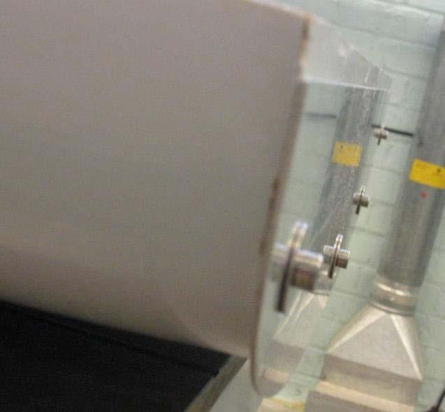
27 Figure 5 Interceptor fitted to model
28 Ct 5.2x x10-3 No Interceptor h/l=0.077% 4.8x10⁻³ h/l=0.154% h/l=0.231% 4.6x x x x x x x x x Fr Ct 5.2x x10-3 Fr=0.290 Fr= x10-3 Fr=0.580 Fr= x x x x x x x x h/l (%) (a) Variation of Total Resistance Coefficient with Froude Number (b) Variation of Total Resistance Coefficient with Interceptor Height Figure 6 Resistance of Yacht with and without Interceptor
29 % change in Ct from bare hull h/l=0.077% h/l=0.154% h/l=0.231% Fr % change in Ct from bare hull Fr=0.290 Fr=0.464 Fr=0.580 Fr= h/l (%) (a) Change in Total Resistance Coefficient with Froude Number (b) Change in Total Resistance Coefficient with Interceptor Height Figure 7 Change in Resistance of Yacht with Interceptor from Bare Hull
30 s/l (%) No Interceptor h/l=0.077% h/l=0.154% h/l=0.231% Fr s/l (%) Fr=0.290 Fr=0.464 Fr=0.580 Fr= h/l (%) (a) Variation of Sinkage with Froude Number (b) Variation of Sinkage with Interceptor Height Figure 8 Sinkage of Yacht with and without Interceptor
31 Trim (deg) 2.4 No Interceptor h/l=0.077% h/l=0.154% 2.0 h/l=0.231% Fr Trim (deg) Fr=0.290 Fr=0.464 Fr=0.580 Fr= h/l (%) (a) Variation of Trim with Froude Number (b) Variation of Trim with Interceptor Height Figure 9 Trim of yachts with and without interceptor
32 No Interceptor h/l=0.077% h/l=0.154% h/l=0.231% Fr=0.290 Fr=0.464 Fr=0.580 Fr=0.755 Transom s/l (%) Transom s/l (%) Fr h/l (%) (a) Variation of Transom Immersion with Froude Number (b) Variation of Transom Immersion with Interceptor Height Figure 10 Transom immersion of Yacht with and without Interceptor
33 5.50E E E E E-3 Varying LCG Original LCG h/l=0.077 h/l=0.154 h/l=0.231 h/l= E E E E E-3 Ct 4.25E-3 Ct 4.25E E E E E E E-3 Varying LCG Original LCG h/l=0.077 h/l=0.154 h/l=0.231 h/l= E E E Trim (deg) 3.00E Trim (deg) (a) Comparison of Resistance at 7.5 knots (b) Comparison of Resistance at 15 knots Varying LCG Original LCG h/l=0.077 h/l=0.154 h/l=0.231 h/l=0.463 s/l (%) 0.08 s/l (%) Varying LCG Original LCG h/l=0.077 h/l=0.154 h/l=0.231 h/l= Trim (deg) Trim (deg) (c) Comparison of Sinkage at 7.5 knots (d) Comparison of Sinkage at 15 knots Transom s/l (%) Varying LCG Original LCG h/l=0.077 h/l=0.154 h/l=0.231 h/l=0.463 Transom s/l (%) Varying LCG Original LCG h/l=0.077 h/l=0.154 h/l=0.231 h/l= Trim (deg) Trim (deg) (e) Comparison of Transom Immersion at 7.5 knots (f) Comparison of Transom Immersion at 15 knots Figure 11 Comparison of Yacht with Interceptor and yacht trimmed via LCG shift
34 Ct 5.50x x x x x x x x x x x10-3 No Interceptor No Interceptor (calm) h/l=0.231% h/l=0.231% (calm) L / lamda Pitch RAO No Interceptor h/l=0.231% L / lamda (a) Variation of Mean Total Resistance Coefficient (b) Variation of Pitch RAO with Interceptor Height with Wavelength Figure 12 Resistance and Pitch RAO of Yacht with and without Interceptor in Waves
Study on Resistance of Stepped Hull Fitted With Interceptor Plate
 39 Study on Resistance of Stepped Hull Fitted With Interceptor Plate Muhamad Asyraf bin Abdul Malek, a, and J.Koto, a,b,* a) Department of Aeronautic, Automotive and Ocean Engineering, Faculty of Mechanical
Experimental and Theoretical Investigation for the Improvement of the Aerodynamic Characteristic of NACA 0012 airfoil
 International Journal of Mining, Metallurgy & Mechanical Engineering (IJMMME) Volume 2, Issue 1 (214) ISSN 232 46 (Online) Experimental and Theoretical Investigation for the Improvement of the Aerodynamic
Numerical and Experimental Investigation of the Possibility of Forming the Wake Flow of Large Ships by Using the Vortex Generators
 Second International Symposium on Marine Propulsors smp 11, Hamburg, Germany, June 2011 Numerical and Experimental Investigation of the Possibility of Forming the Wake Flow of Large Ships by Using the
Interceptors in theory and practice
 Interceptors in theory and practice An interceptor is a small vertical plate, usually located at the trailing edge on the pressure side of a foil. The effect is a completely different pressure distribution
Aerodynamic Analysis of a Symmetric Aerofoil
 214 IJEDR Volume 2, Issue 4 ISSN: 2321-9939 Aerodynamic Analysis of a Symmetric Aerofoil Narayan U Rathod Department of Mechanical Engineering, BMS college of Engineering, Bangalore, India Abstract - The
ITTC Recommended Procedures and Guidelines
 Page 1 of 6 Table of Contents 1. PURPOSE...2 2. PARAMETERS...2 2.1 General Considerations...2 3 DESCRIPTION OF PROCEDURE...2 3.1 Model Design and Construction...2 3.2 Measurements...3 3.5 Execution of
THE PERFORMANCE OF PLANING HULLS IN TRANSITION SPEEDS
 THE PERFORMANCE OF PLANING HULLS IN TRANSITION SPEEDS BY DOYOON KIM UNIVERSITY OF SOUTHAMPTON LIST OF CONTENTS AIM & OBJECTIVE HYDRODYNAMIC PHENOMENA OF PLANING HULLS TOWING TANK TEST RESULTS COMPUTATIONAL
STUDIES ON THE OPTIMUM PERFORMANCE OF TAPERED VORTEX FLAPS
 ICAS 2000 CONGRESS STUDIES ON THE OPTIMUM PERFORMANCE OF TAPERED VORTEX FLAPS Kenichi RINOIE Department of Aeronautics and Astronautics, University of Tokyo, Tokyo, 113-8656, JAPAN Keywords: vortex flap,
A Study on Roll Damping of Bilge Keels for New Non-Ballast Ship with Rounder Cross Section
 International Ship Stability Workshop 2013 1 A Study on Roll Damping of Bilge Keels for New Non-Ballast Ship with Rounder Cross Section Tatsuya Miyake and Yoshiho Ikeda Department of Marine System Engineering,
EXPERIMENTAL MEASUREMENT OF THE WASH CHARACTERISTICS OF A FAST DISPLACEMENT CATAMARAN IN DEEP WATER
 EXPERIMENTAL MEASUREMENT OF THE WASH CHARACTERISTICS OF A FAST DISPLACEMENT CATAMARAN IN DEEP WATER A.F. Molland, P.A. Wilson and D.J. Taunton Ship Science Report No. 124 University of Southampton December
AERODYNAMIC CHARACTERISTICS OF NACA 0012 AIRFOIL SECTION AT DIFFERENT ANGLES OF ATTACK
 AERODYNAMIC CHARACTERISTICS OF NACA 0012 AIRFOIL SECTION AT DIFFERENT ANGLES OF ATTACK SUPREETH NARASIMHAMURTHY GRADUATE STUDENT 1327291 Table of Contents 1) Introduction...1 2) Methodology.3 3) Results...5
CRITERIA OF BOW-DIVING PHENOMENA FOR PLANING CRAFT
 531 CRITERIA OF BOW-DIVING PHENOMENA FOR PLANING CRAFT Toru KATAYAMA, Graduate School of Engineering, Osaka Prefecture University (Japan) Kentarou TAMURA, Universal Shipbuilding Corporation (Japan) Yoshiho
A HYDRODYNAMIC METHODOLOGY AND CFD ANALYSIS FOR PERFORMANCE PREDICTION OF STEPPED PLANING HULLS
 POLISH MARITIME RESEARCH 2(86) 2015 Vol. 22; pp. 23-31 10.1515/pomr-2015-0014 A HYDRODYNAMIC METHODOLOGY AND CFD ANALYSIS FOR PERFORMANCE PREDICTION OF STEPPED PLANING HULLS Hassan Ghassemi, Assoc. Prof.
CFD AND EXPERIMENTAL STUDY OF AERODYNAMIC DEGRADATION OF ICED AIRFOILS
 Colloquium FLUID DYNAMICS 2008 Institute of Thermomechanics AS CR, v.v.i., Prague, October 22-24, 2008 p.1 CFD AND EXPERIMENTAL STUDY OF AERODYNAMIC DEGRADATION OF ICED AIRFOILS Vladimír Horák 1, Dalibor
Chapter 2 Hydrostatics and Control
 Chapter 2 Hydrostatics and Control Abstract A submarine must conform to Archimedes Principle, which states that a body immersed in a fluid has an upward force on it (buoyancy) equal to the weight of the
SEMI-SPAN TESTING IN WIND TUNNELS
 25 TH INTERNATIONAL CONGRESS OF THE AERONAUTICAL SCIENCES SEMI-SPAN TESTING IN WIND TUNNELS S. Eder, K. Hufnagel, C. Tropea Chair of Fluid Mechanics and Aerodynamics, Darmstadt University of Technology
A COMPUTATIONAL STUDY ON THE DESIGN OF AIRFOILS FOR A FIXED WING MAV AND THE AERODYNAMIC CHARACTERISTIC OF THE VEHICLE
 28 TH INTERNATIONAL CONGRESS OF THE AERONAUTICAL SCIENCES A COMPUTATIONAL STUDY ON THE DESIGN OF AIRFOILS FOR A FIXED WING MAV AND THE AERODYNAMIC CHARACTERISTIC OF THE VEHICLE Jung-Hyun Kim*, Kyu-Hong
Figure 1 Figure 1 shows the involved forces that must be taken into consideration for rudder design. Among the most widely known profiles, the most su
 THE RUDDER starting from the requirements supplied by the customer, the designer must obtain the rudder's characteristics that satisfy such requirements. Subsequently, from such characteristics he must
AERODYNAMICS I LECTURE 7 SELECTED TOPICS IN THE LOW-SPEED AERODYNAMICS
 LECTURE 7 SELECTED TOPICS IN THE LOW-SPEED AERODYNAMICS The sources of a graphical material used in this lecture are: [UA] D. McLean, Understanding Aerodynamics. Arguing from the Real Physics. Wiley, 2013.
EXPERIMENTAL ANALYSIS OF THE CONFLUENT BOUNDARY LAYER BETWEEN A FLAP AND A MAIN ELEMENT WITH SAW-TOOTHED TRAILING EDGE
 24 TH INTERNATIONAL CONGRESS OF THE AERONAUTICAL SCIENCES EXPERIMENTAL ANALYSIS OF THE CONFLUENT BOUNDARY LAYER BETWEEN A FLAP AND A MAIN ELEMENT WITH SAW-TOOTHED TRAILING EDGE Lemes, Rodrigo Cristian,
NUMERICAL INVESTIGATION FOR THE ENHANCEMENT OF THE AERODYNAMIC CHARACTERISTICS OF AN AEROFOIL BY USING A GURNEY FLAP
 Geotec., Const. Mat. & Env., ISSN:2186-2990, Japan, DOI: http://dx.doi.org/10.21660/2017.34.2650 NUMERICAL INVESTIGATION FOR THE ENHANCEMENT OF THE AERODYNAMIC CHARACTERISTICS OF AN AEROFOIL BY USING A
STABILITY OF MULTIHULLS Author: Jean Sans
 STABILITY OF MULTIHULLS Author: Jean Sans (Translation of a paper dated 10/05/2006 by Simon Forbes) Introduction: The capsize of Multihulls requires a more exhaustive analysis than monohulls, even those
A STUDY OF THE LOSSES AND INTERACTIONS BETWEEN ONE OR MORE BOW THRUSTERS AND A CATAMARAN HULL
 A STUDY OF THE LOSSES AND INTERACTIONS BETWEEN ONE OR MORE BOW THRUSTERS AND A CATAMARAN HULL L Boddy and T Clarke, Austal Ships, Australia SUMMARY CFD analysis has been conducted on a 100m catamaran hull
The effect of back spin on a table tennis ball moving in a viscous fluid.
 How can planes fly? The phenomenon of lift can be produced in an ideal (non-viscous) fluid by the addition of a free vortex (circulation) around a cylinder in a rectilinear flow stream. This is known as
PERFORMANCE PREDICTION OF THE PLANING YACHT HULL
 PERFORMANCE PREDICTION OF THE PLANING YACHT HULL L A le Clercq and D A Hudson, University of Southampton, UK SUMMARY The performance of racing yachts has increased significantly over the past 10-15 years
EXPERIMENTAL ANALYSIS OF FLOW OVER SYMMETRICAL AEROFOIL Mayank Pawar 1, Zankhan Sonara 2 1,2
 EXPERIMENTAL ANALYSIS OF FLOW OVER SYMMETRICAL AEROFOIL Mayank Pawar 1, Zankhan Sonara 2 1,2 Assistant Professor,Chandubhai S. Patel Institute of Technology, CHARUSAT, Changa, Gujarat, India Abstract The
PRESSURE DISTRIBUTION OF SMALL WIND TURBINE BLADE WITH WINGLETS ON ROTATING CONDITION USING WIND TUNNEL
 International Journal of Mechanical and Production Engineering Research and Development (IJMPERD ) ISSN 2249-6890 Vol.2, Issue 2 June 2012 1-10 TJPRC Pvt. Ltd., PRESSURE DISTRIBUTION OF SMALL WIND TURBINE
Development of Technology to Estimate the Flow Field around Ship Hull Considering Wave Making and Propeller Rotating Effects
 Development of Technology to Estimate the Flow Field around Ship Hull Considering Wave Making and Propeller Rotating Effects 53 MAKOTO KAWABUCHI *1 MASAYA KUBOTA *1 SATORU ISHIKAWA *2 As can be seen from
NUMERICAL INVESTIGATION OF AERODYNAMIC CHARACTERISTICS OF NACA AIRFOIL WITH A GURNEY FLAP
 Int. J. Mech. Eng. & Rob. Res. 2012 MasoudJahanmorad Nouri et al., 2012 Research Paper ISSN 2278 0149 www.ijmerr.com Vol. 1, No. 3, October 2012 2012 IJMERR. All Rights Reserved NUMERICAL INVESTIGATION
Effect of Co-Flow Jet over an Airfoil: Numerical Approach
 Contemporary Engineering Sciences, Vol. 7, 2014, no. 17, 845-851 HIKARI Ltd, www.m-hikari.com http://dx.doi.org/10.12988/ces.2014.4655 Effect of Co-Flow Jet over an Airfoil: Numerical Approach Md. Riajun
ITTC Recommended Procedures and Guidelines
 7.5- -- Page 1 of 6 Table of Contents 1 PURPOSE OF PROCEDURE 2 2 PARAMETERS...2 2.1 Definition of Variables...2 3 DESCRIPTION OF PROCEDURE...2 3.1...2 3.1.1 Hull Model...2 3.1.2 Propeller Model...3 3.1.3
ITTC - Recommended Procedures and Guidelines
 7.5 Page 1 of 5 Table of Contents 1. PURPOSE OF PROCEDURE... 2 2. DESCRIPTION OF PROCEDURE... 2 4. DOCUMENTATION... 4 5. REFERENCES... 4 3. PARAMETERS... 4 Updated by Approved Manoeuvring Committee of
The Usage of Propeller Tunnels For Higher Efficiency and Lower Vibration. M. Burak Şamşul
 The Usage of Propeller Tunnels For Higher Efficiency and Lower Vibration M. Burak Şamşul ITU AYOC 2014 - Milper Pervane Teknolojileri Company Profile MILPER is established in 2011 as a Research and Development
Reduction of Skin Friction Drag in Wings by Employing Riblets
 Reduction of Skin Friction Drag in Wings by Employing Riblets Kousik Kumaar. R 1 Assistant Professor Department of Aeronautical Engineering Nehru Institute of Engineering and Technology Coimbatore, India
Influence of rounding corners on unsteady flow and heat transfer around a square cylinder
 Influence of rounding corners on unsteady flow and heat transfer around a square cylinder S. K. Singh Deptt. of Mech. Engg., M. B. M. Engg. College / J. N. V. University, Jodhpur, Rajasthan, India Abstract
EFFECT OF GURNEY FLAPS AND WINGLETS ON THE PERFORMANCE OF THE HAWT
 Chapter-6 EFFECT OF GURNEY FLAPS AND WINGLETS ON THE PERFORMANCE OF THE HAWT 6.1 Introduction The gurney flap (wicker bill) was a small flat tab projecting from the trailing edge of a wing. Typically it
Investigation on 3-D Wing of commercial Aeroplane with Aerofoil NACA 2415 Using CFD Fluent
 Investigation on 3-D of commercial Aeroplane with Aerofoil NACA 2415 Using CFD Fluent Rohit Jain 1, Mr. Sandeep Jain 2, Mr. Lokesh Bajpai 3 1PG Student, 2 Associate Professor, 3 Professor & Head 1 2 3
Incompressible Potential Flow. Panel Methods (3)
") Incompressible Potential Flow Panel Methods (3) Outline Some Potential Theory Derivation of the Integral Equation for the Potential Classic Panel Method Program PANEL Subsonic Airfoil Aerodynamics Issues
Incompressible Potential Flow Panel Methods (3) Outline Some Potential Theory Derivation of the Integral Equation for the Potential Classic Panel Method Program PANEL Subsonic Airfoil Aerodynamics Issues
SECOND ENGINEER REG III/2 NAVAL ARCHITECTURE
 SECOND ENGINEER REG III/2 NAVAL ARCHITECTURE LIST OF TOPICS A B C D E F G H I J Hydrostatics Simpson's Rule Ship Stability Ship Resistance Admiralty Coefficients Fuel Consumption Ship Terminology Ship
Design of high-speed planing hulls for the improvement of resistance and seakeeping performance
 csnak, 2013 Int. J. Naval Archit. Ocean Eng. (2013) 5:161~177 http://dx.doi.org/10.2478/ijnaoe-2013-0124 Design of high-speed planing hulls for the improvement of resistance and seakeeping performance
Journal of Naval Architecture and Marine Engineering December,
 Journal of Naval Architecture and Marine Engineering December, 5 http://dx.doi.org http://dx.doi.org/.339/jname.vi.35 http://www.banglajol.info INTRODUCING A PARTICULAR MATHEMATICALMODEL FOR PREDICTING
Design & Analysis of Natural Laminar Flow Supercritical Aerofoil for Increasing L/D Ratio Using Gurney Flap
 Design & Analysis of Natural Laminar Flow Supercritical Aerofoil for Increasing L/D Ratio Using Gurney Flap U.Praveenkumar 1, E.T.Chullai 2 M.Tech Student, School of Aeronautical Science, Hindustan University,
Tim Lee s journal publications
 Tim Lee s journal publications 82. Lee, T., and Tremblay-Dionne, V., (2018) Impact of wavelength and amplitude of a wavy ground on a static NACA 0012 airfoil submitted to Journal of Aircraft (paper in
JOURNAL PUBLICATIONS
 1 JOURNAL PUBLICATIONS 71. Lee, T., Mageed, A., Siddiqui, B. and Ko, L.S., (2016) Impact of ground proximity on aerodynamic properties of an unsteady NACA 0012 airfoil, submitted to Journal of Aerospace
The Windward Performance of Yachts in Rough Water
 14th Chesapeake Sailing Yacht Symposium January 3, 1999 The Windward Performance of Yachts in Rough Water Jonathan R. Binns, Australian Maritime Engineering Cooperative Research Centre Ltd. (AME CRC) Bruce
CASE STUDY FOR USE WITH SECTION B
 GCE A level 135/01-B PHYSICS ASSESSMENT UNIT PH5 A.M. THURSDAY, 0 June 013 CASE STUDY FOR USE WITH SECTION B Examination copy To be given out at the start of the examination. The pre-release copy must
Vessel Modification and Hull Maintenance Considerations Options & Pay Back Period or Return On Investments
 Vessel Modification and Hull Maintenance Considerations Options & Pay Back Period or Return On Investments By Dag Friis Christian Knapp Bob McGrath Ocean Engineering Research Centre MUN Engineering 1 Overview:
Pressure distribution of rotating small wind turbine blades with winglet using wind tunnel
 Journal of Scientific SARAVANAN & Industrial et al: Research PRESSURE DISTRIBUTION OF SMALL WIND TURBINE BLADES WITH WINGLET Vol. 71, June 01, pp. 45-49 45 Pressure distribution of rotating small wind
Aerodynamic Analysis of Blended Winglet for Low Speed Aircraft
 , July 1-3, 2015, London, U.K. Aerodynamic Analysis of Blended Winglet for Low Speed Aircraft Pooja Pragati, Sudarsan Baskar Abstract This paper provides a practical design of a new concept of massive
ZIPWAKE DYNAMIC TRIM CONTROL SYSTEM OUTLINE OF OPERATING PRINCIPLES BEHIND THE AUTOMATIC MOTION CONTROL FEATURES
 ZIPWAKE DYNAMIC TRIM CONTROL SYSTEM OUTLINE OF OPERATING PRINCIPLES BEHIND THE AUTOMATIC MOTION CONTROL FEATURES TABLE OF CONTENTS 1 INTRODUCTION 3 2 SYSTEM COMPONENTS 3 3 PITCH AND ROLL ANGLES 4 4 AUTOMATIC
A comparison of NACA 0012 and NACA 0021 self-noise at low Reynolds number
 A comparison of NACA 12 and NACA 21 self-noise at low Reynolds number A. Laratro, M. Arjomandi, B. Cazzolato, R. Kelso Abstract The self-noise of NACA 12 and NACA 21 airfoils are recorded at a Reynolds
ROAD MAP... D-1: Aerodynamics of 3-D Wings D-2: Boundary Layer and Viscous Effects D-3: XFLR (Aerodynamics Analysis Tool)
") Unit D-1: Aerodynamics of 3-D Wings Page 1 of 5 AE301 Aerodynamics I UNIT D: Applied Aerodynamics ROAD MAP... D-1: Aerodynamics of 3-D Wings D-: Boundary Layer and Viscous Effects D-3: XFLR (Aerodynamics
Unit D-1: Aerodynamics of 3-D Wings Page 1 of 5 AE301 Aerodynamics I UNIT D: Applied Aerodynamics ROAD MAP... D-1: Aerodynamics of 3-D Wings D-: Boundary Layer and Viscous Effects D-3: XFLR (Aerodynamics
The Effect of Mast Height and Centre of Gravity on the Re-righting of Sailing Yachts
 THE 17 th CHESAPEAKE SAILING YACHT SYMPOSIUM ANNAPOLIS, MARYLAND, MARCH 25 The Effect of Mast Height and Centre of Gravity on the Re-righting of Sailing Yachts Jonathan R. Binns, Researcher, Australian
It should be noted that the symmetrical airfoil at zero lift has no pitching moment about the aerodynamic center because the upper and
 NAVWEPS -81-8 and high power, the dynamic pressure in the shaded area can be much greater than the free stream and this causes considerably greater lift than at zero thrust. At high power conditions the
ANALYSIS OF AERODYNAMIC CHARACTERISTICS OF A SUPERCRITICAL AIRFOIL FOR LOW SPEED AIRCRAFT
 ANALYSIS OF AERODYNAMIC CHARACTERISTICS OF A SUPERCRITICAL AIRFOIL FOR LOW SPEED AIRCRAFT P.Sethunathan 1, M.Niventhran 2, V.Siva 2, R.Sadhan Kumar 2 1 Asst.Professor, Department of Aeronautical Engineering,
Development of TEU Type Mega Container Carrier
 Development of 8 700 TEU Type Mega Container Carrier SAKAGUCHI Katsunori : P. E. Jp, Manager, Ship & Offshore Basic Design Department, IHI Marine United Inc. TOYODA Masanobu : P. E, Jp, Ship & Offshore
CFD Study of Solid Wind Tunnel Wall Effects on Wing Characteristics
 Indian Journal of Science and Technology, Vol 9(45), DOI :10.17485/ijst/2016/v9i45/104585, December 2016 ISSN (Print) : 0974-6846 ISSN (Online) : 0974-5645 CFD Study of Solid Wind Tunnel Wall Effects on
CFD ANALYSIS OF FLOW AROUND AEROFOIL FOR DIFFERENT ANGLE OF ATTACKS
 www.mechieprojects.com CFD ANALYSIS OF FLOW AROUND AEROFOIL FOR DIFFERENT ANGLE OF ATTACKS PRESENTATION OUTLINE AIM INTRODUCTION LITERATURE SURVEY CFD ANALYSIS OF AEROFOIL RESULTS CONCLUSIONS www.mechieprojects.com
The Fly Higher Tutorial IV
 The Fly Higher Tutorial IV THE SCIENCE OF FLIGHT In order for an aircraft to fly we must have two things: 1) Thrust 2) Lift Aerodynamics The Basics Representation of the balance of forces These act against
J. Szantyr Lecture No. 21 Aerodynamics of the lifting foils Lifting foils are important parts of many products of contemporary technology.
 J. Szantyr Lecture No. 21 Aerodynamics of the lifting foils Lifting foils are important parts of many products of contemporary technology. < Helicopters Aircraft Gliders Sails > < Keels and rudders Hydrofoils
Aircraft Design Prof. A.K Ghosh Department of Aerospace Engineering Indian Institute of Technology, Kanpur
 Aircraft Design Prof. A.K Ghosh Department of Aerospace Engineering Indian Institute of Technology, Kanpur Lecture - 12 Design Considerations: Aerofoil Selection Good morning friends. The last lecture
Aerodynamic Terms. Angle of attack is the angle between the relative wind and the wing chord line. [Figure 2-2] Leading edge. Upper camber.
![Aerodynamic Terms. Angle of attack is the angle between the relative wind and the wing chord line. [Figure 2-2] Leading edge. Upper camber.](/thumbs/82/86661300.jpg "Aerodynamic Terms. Angle of attack is the angle between the relative wind and the wing chord line. [Figure 2-2] Leading edge. Upper camber.") Chapters 2 and 3 of the Pilot s Handbook of Aeronautical Knowledge (FAA-H-8083-25) apply to powered parachutes and are a prerequisite to reading this book. This chapter will focus on the aerodynamic fundamentals
Chapters 2 and 3 of the Pilot s Handbook of Aeronautical Knowledge (FAA-H-8083-25) apply to powered parachutes and are a prerequisite to reading this book. This chapter will focus on the aerodynamic fundamentals
External Tank- Drag Reduction Methods and Flow Analysis
 External Tank- Drag Reduction Methods and Flow Analysis Shaik Mohammed Anis M.Tech Student, MLR Institute of Technology, Hyderabad, India. G. Parthasarathy Associate Professor, MLR Institute of Technology,
AN UPDATE ON THE DEVELOPMENT OF THE HULL VANE
 AN UPDATE ON THE DEVELOPMENT OF THE HULL VANE K. Uithof 1, P. van Oossanen 1,2, N. Moerke 1,2, P.G. van Oossanen 1,2, and K.S. Zaaijer 2 1 Hull Vane B.V., Costerweg 1b, 6702 AA, Wageningen, Netherlands
MEDIUM SPEED CATAMARAN WITH LARGE CENTRAL BULBS: EXPERIMENTAL INVESTIGATION ON RESISTANCE AND VERTICAL MOTIONS
 MEDIUM SPEED CATAMARAN WITH LARGE CENTRAL BULBS: EXPERIMENTAL INVESTIGATION ON RESISTANCE AND VERTICAL MOTIONS Igor Zotti, University of Trieste, Department D.I.N.M.A., Italy SUMMARY: It has been noticed
ScienceDirect. Investigation of the aerodynamic characteristics of an aerofoil shaped fuselage UAV model
 Available online at www.sciencedirect.com ScienceDirect Procedia Engineering 90 (2014 ) 225 231 10th International Conference on Mechanical Engineering, ICME 2013 Investigation of the aerodynamic characteristics
Lift for a Finite Wing. all real wings are finite in span (airfoils are considered as infinite in the span)
") Lift for a Finite Wing all real wings are finite in span (airfoils are considered as infinite in the span) The lift coefficient differs from that of an airfoil because there are strong vortices produced
Lift for a Finite Wing all real wings are finite in span (airfoils are considered as infinite in the span) The lift coefficient differs from that of an airfoil because there are strong vortices produced
Analysis of Hull Shape Effects on Hydrodynamic Drag in Offshore Handicap Racing Rules
 THE 16 th CHESAPEAKE SAILING YACHT SYMPOSIUM ANNAPOLIS, MARYLAND, MARCH 2003 Analysis of Hull Shape Effects on Hydrodynamic Drag in Offshore Handicap Racing Rules Jim Teeters, Director of Research for
COMPUTER-AIDED DESIGN AND PERFORMANCE ANALYSIS OF HAWT BLADES
 5 th International Advanced Technologies Symposium (IATS 09), May 13-15, 2009, Karabuk, Turkey COMPUTER-AIDED DESIGN AND PERFORMANCE ANALYSIS OF HAWT BLADES Emrah KULUNK a, * and Nadir YILMAZ b a, * New
Flat Water Racing Kayak Resistance Study 1
 Flat Water Racing Kayak Resistance Study 1 Article Type: Research Article Article Category: Sports Coaching Tittle: Experimental and Numerical Study of the Flow past Olympic Class K 1 Flat Water Racing
CFD Analysis ofwind Turbine Airfoil at Various Angles of Attack
 IOSR Journal of Mechanical and Civil Engineering (IOSR-JMCE) e-issn: 2278-1684,p-ISSN: 2320-334X, Volume 13, Issue 4 Ver. II (Jul. - Aug. 2016), PP 18-24 www.iosrjournals.org CFD Analysis ofwind Turbine
In parallel with steady gains in battery energy and power density, the coming generation of uninhabited aerial vehicles (UAVs) will enjoy increased
 will enjoy increased") In parallel with steady gains in battery energy and power density, the coming generation of uninhabited aerial vehicles (UAVs) will enjoy increased range, endurance, and operational capability by exploiting
In parallel with steady gains in battery energy and power density, the coming generation of uninhabited aerial vehicles (UAVs) will enjoy increased range, endurance, and operational capability by exploiting
Improvement of an Artificial Stall Warning System for Sailplanes
 Improvement of an Artificial Stall Warning System for Sailplanes Loek M. M. Boermans and Bart Berendsen Delft University of Technology, Faculty of Aerospace Engineering P.O.Box 5058, 2600 GB Delft, The
Measurement and simulation of the flow field around a triangular lattice meteorological mast
 Measurement and simulation of the flow field around a triangular lattice meteorological mast Matthew Stickland 1, Thomas Scanlon 1, Sylvie Fabre 1, Andrew Oldroyd 2 and Detlef Kindler 3 1. Department of
2-D Computational Analysis of a Vertical Axis Wind Turbine Airfoil
 2-D Computational Analysis of a Vertical Axis Wind Turbine Airfoil Akshay Basavaraj1 Student, Department of Aerospace Engineering, Amrita School of Engineering, Coimbatore 641 112, India1 Abstract: This
SOARING AND GLIDING FLIGHT OF THE BLACK VULTURE
 [ 280 ] SOARING AND GLIDING FLIGHT OF THE BLACK VULTURE BY B. G. NEWMAN* Department of Engineering, University of Cambridge {Received 10 September 1957) INTRODUCTION In 1950 Raspet published an interesting
Welcome to Aerospace Engineering
 Welcome to Aerospace Engineering DESIGN-CENTERED INTRODUCTION TO AEROSPACE ENGINEERING Notes 4 Topics 1. Course Organization 2. Today's Dreams in Various Speed Ranges 3. Designing a Flight Vehicle: Route
EXPERIMENTAL AND ANALYTICAL INVESTIGATION OF THE EFFECT OF BODY KIT USED WITH SALOON CARS IN BRUNEI DARUSSALAM
 EXPERIMENTAL AND ANALYTICAL INVESTIGATION OF THE EFFECT OF BODY KIT USED WITH SALOON CARS IN BRUNEI DARUSSALAM M.G., Yazdani, H. Ullah, T. Aderis and R. Zainulariffin, Faculty of Engineering, Institut
Lab test 4 Seakeeping test with a model of an oil tanker
 Lab test 4 Seakeeping test with a model of an oil tanker The response amplitude operators (RAO) in head seas of a 1:100 scale model of a 257 m long oil tanker shall be determined by model testing in the
ITTC Recommended Procedures Testing and Extrapolation Methods Loads and Responses, Seakeeping Experiments on Rarely Occurring Events
 Loads and Responses, Seakeeping Page 1 of 5 CONTENTS 1. PURPOSE OF PROCEDURE 2. STANDARDS FOR EXPERIMENTS ON RARELY OCCURRING EVENTS 2.1 Previous Recommendations of ITTC 2.2 Model Design and Construction
Parasite Drag. by David F. Rogers Copyright c 2005 David F. Rogers. All rights reserved.
 Parasite Drag by David F. Rogers http://www.nar-associates.com Copyright c 2005 David F. Rogers. All rights reserved. How many of you still have a Grimes rotating beacon on both the top and bottom of the
On the Hydrodynamics of a Skiff at Different Crew Positions
 THE 21 st CHESAPEAKE SAILING YACHT SYMPOSIUM ANNAPOLIS, MARYLAND, MARCH 2013 On the Hydrodynamics of a Skiff at Different Crew Positions Ignazio Maria Viola and Joshua Enlander, Yacht and Superyacht Research
AERODYNAMIC CHARACTERISTICS OF SPIN PHENOMENON FOR DELTA WING
 ICAS 2002 CONGRESS AERODYNAMIC CHARACTERISTICS OF SPIN PHENOMENON FOR DELTA WING Yoshiaki NAKAMURA (nakamura@nuae.nagoya-u.ac.jp) Takafumi YAMADA (yamada@nuae.nagoya-u.ac.jp) Department of Aerospace Engineering,
Application of Simulation Technology to Mitsubishi Air Lubrication System
 50 Application of Simulation Technology to Mitsubishi Air Lubrication System CHIHARU KAWAKITA *1 SHINSUKE SATO *2 TAKAHIRO OKIMOTO *2 For the development and design of the Mitsubishi Air Lubrication System
COURSE OBJECTIVES CHAPTER 9
 COURSE OBJECTIVES CHAPTER 9 9. SHIP MANEUVERABILITY 1. Be qualitatively familiar with the 3 broad requirements for ship maneuverability: a. Controls fixed straightline stability b. Response c. Slow speed
An Impeller Blade Analysis of Centrifugal Gas Compressor Using CFD
 An Impeller Blade Analysis of Centrifugal Gas Compressor Using CFD Vivek V. Kulkarni Department of Mechanical Engineering KLS Gogte Institute of Technology, Belagavi, Karnataka Dr. Anil T.R. Department
Unsteady airfoil experiments
 Unsteady airfoil experiments M.F. Platzer & K.D. Jones AeroHydro Research & Technology Associates, Pebble Beach, CA, USA. Abstract This paper describes experiments that elucidate the dynamic stall phenomenon
SHIP FORM DEFINITION The Shape of a Ship
 SHIP FORM DEFINITION The Shape of a Ship The Traditional Way to Represent the Hull Form A ship's hull is a very complicated three dimensional shape. With few exceptions an equation cannot be written that
Effect of High-Lift Devices on Aircraft Wing
 IOSR Journal of Engineering (IOSRJEN) ISSN (e): 2250-3021, ISSN (p): 2278-8719 PP 01-05 www.iosrjen.org Effect of High-Lift Devices on Aircraft Wing Gaurav B. Mungekar 1, Swapnil N. More 1, Samadhan V.
WATER-FREE IOM MEASUREMENT IOMICA, 2005 March 4
 WATER-FREE IOM MEASUREMENT IOMICA, 2005 March 4 The IOM has grown to become the most broadly accepted radio sailing class worldwide. To a large degree that success can be attributed to a strong set of
HULL VANE VERSUS LENGTHENING A comparison between four alternatives for a 61m OPV
 HULL VANE VERSUS LENGTHENING A comparison between four alternatives for a 61m OPV N. Hagemeister (van Oossanen Fluid Dynamics), n.hagemeister@oossanen.nl K. Uithof (Hull Vane B.V.), k.uithof@hullvane.com
Principles of glider flight
 Principles of glider flight [ Lecture 1: Lift, drag & glide performance ] Richard Lancaster Email: Richard@RJPLancaster.net Twitter: @RJPLancaster ASK-21 illustrations Copyright 1983 Alexander Schleicher
THE BRIDGE COLLAPSED IN NOVEMBER 1940 AFTER 4 MONTHS OF ITS OPENING TO TRAFFIC!
 OUTLINE TACOMA NARROWS BRIDGE FLOW REGIME PAST A CYLINDER VORTEX SHEDDING MODES OF VORTEX SHEDDING PARALLEL & OBLIQUE FLOW PAST A SPHERE AND A CUBE SUMMARY TACOMA NARROWS BRIDGE, USA THE BRIDGE COLLAPSED
II.E. Airplane Flight Controls
 References: FAA-H-8083-3; FAA-8083-3-25 Objectives Key Elements Elements Schedule Equipment IP s Actions SP s Actions Completion Standards The student should develop knowledge of the elements related to
Conventional Ship Testing
 Conventional Ship Testing Experimental Methods in Marine Hydrodynamics Lecture in week 34 Chapter 6 in the lecture notes 1 Conventional Ship Testing - Topics: Resistance tests Propeller open water tests
DEFINITIONS. Aerofoil
 Aerofoil DEFINITIONS An aerofoil is a device designed to produce more lift (or thrust) than drag when air flows over it. Angle of Attack This is the angle between the chord line of the aerofoil and the
THEORETICAL EVALUATION OF FLOW THROUGH CENTRIFUGAL COMPRESSOR STAGE
 THEORETICAL EVALUATION OF FLOW THROUGH CENTRIFUGAL COMPRESSOR STAGE S.Ramamurthy 1, R.Rajendran 1, R. S. Dileep Kumar 2 1 Scientist, Propulsion Division, National Aerospace Laboratories, Bangalore-560017,ramamurthy_srm@yahoo.com
Aerodynamic investigations on a wing in ground effect
 Aerodynamic investigations on a wing in ground effect A summary of NLR activities in the Seabus-Hydaer programme W.B. de Wolf Nationaal Lucht- en Ruimtevaartlaboratorium National Aerospace Laboratory NLR
5th Symposium on Integrating CFD and Experiments in Aerodynamics (Integration 2012) th Symposium on Integrating CFD and Experiments in Aerodynam
 th Symposium on Integrating CFD and Experiments in Aerodynam") 5th Symposium on Integrating CFD and Experiments in Aerodynamics (Integration 202) 36 Multi-objective Optimization of Airfoil of Mars Exploration Aircraft using Evolutionary Algorithm Gaku Sasaki Tomoaki
5th Symposium on Integrating CFD and Experiments in Aerodynamics (Integration 202) 36 Multi-objective Optimization of Airfoil of Mars Exploration Aircraft using Evolutionary Algorithm Gaku Sasaki Tomoaki
THE EFFECT OF HEEL ANGLE AND FREE-SURFACE PROXIMITY ON THE PERFORMANCE AND STRUT WAKE OF A MOTH SAILING DINGHY RUDDER T-FOIL
 3 rd High Performance Yacht Design Conference Auckland, 2-4 December, 2008 THE EFFECT OF HEEL ANGLE AND FREE-SURFACE PROXIMITY ON THE PERFORMANCE AND STRUT WAKE OF A MOTH SAILING DINGHY RUDDER T-FOIL Jonathan