M32 CATAMARAN ASSEMBLY MANUAL
|
|
|
- Egbert Miles
- 5 years ago
- Views:
Transcription
1 M32 CATAMARAN ASSEMBLY MANUAL 1
2 M32 CATAMARAN ASSEMBLY MANUAL MANUAL SUMMARY M32 ASSEMBLY Parts and tools Instructions MAST PLATFORM Parts and tools Instructions MAST STEPPING Instructions MAIN HALYARD LOCK Instructions This manual is a guide for assembling the boat and stepping the mast and AHC takes no responsibility for damages caused while assembling the boat. If a problem or irregularity arises while assembling the boat, contact your local M32 representative. 2
3
4 M32 CATAMARAN MANUAL SUMMARY The instructions in this manual are made with the intention of making owners safely use the boat for training and racing. The M32 is a high performance competiton boat designed and dimensioned for inshore racing and should be used accordingly. WE WANT TO STRESS THE IMPORTANCE OF HAVING THE RIG ACCORDING TO THE RECOMMEN- DED SETTINGS WITH THE SPREADER ANGLE, PREBEND, DIAMOND TENSION AND MAST RAKE BEING THE KEY PARAMETERS. Spreader angle should be between mm Prebend should be a minimum of 70mm with full main and 80mm when sailing with a reef. When measuring the prebend the mast supports shall be placed 150cm above the bottom end of the mast and one 20cm above the upper diamond stay fitting. The diamond tension using the Loos & Co. gauge RT-10M(3,2-7,1mm) with the base of the gauge in just above the mast winch is recommended to be in the interval If the required prebend is not reached at 55 on the gauge the spreader angle needs to be adjusted. Mast rake should be 480mm 4
5 ADDITIONAL IMPORTANT INFORMATION WHILE SAILING: The recommendation is that a maximum of one person tensions the gennaker tack line. It is key that this is not tightened excessively as it is increasing the compression of the mast dramatically. The forestays and shrouds should be tight at all times so they need to be tightened if they stretch. The forestays take the majority of the load going upwind, not the gennaker luff. When not manuevering only one daggerboard should be fully down The mainsheet and traveler combined is supporting the mast both upwind and downwind and the gennaker needs to be eased prior to the mainsheet when depowering the sails. To prevent damage to the rudders do not let the tiller go while reversing, this is overloading the rudder head as well as the blade. Ensure that the cunningham line is not resting on the diamond stay, a dyneema can be put around the gooseneck to get a better angle for the ring/block 5

6 MAST ASSEMBLY PARTS AND TOOLS PARTS INCLUDED 1 Diamond stays, longer 4 Halyards 2 Diamond stays, shorter 5 Forestays/Shrouds mounted on t-tang 3 Spreaders 6 Winch handle IMPORTANT! The diamond stays should be handled with care and kept secured in the bowsprit during transport. 6

7 TOOLS INCLUDED Socket wrench for adjusting diamond tension Grease, Rocol ANTI-SIEZE stainless or similar Torx wrench kit Electrical Tape Dynema with shockchord for measuring spreader angle (p. 9 9) Folding Rule 7
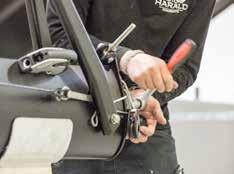
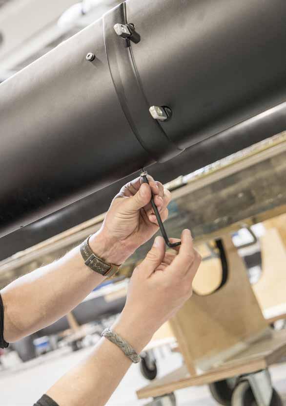
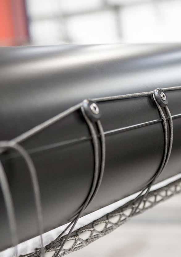
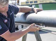
8 MAST ASSEMBLY INSTRUCTIONS MAST ASSEMBLY 1 2a 2b 3 Place the lower and upper mast tubes collinear to each other either on stands or padding on the ground. Push the two mast halves together and insert and tighten lightly the 6 M6 screw that locks the lower and upper mast tubes together, (2 on the leading edge and 2 on each side close to the trailing edge). Make sure that the mast halves are a tight fit, if this is not the case this needs to be ensured by bedding the joint with adhesive Connect the spreaders to the mast; the key ring shall be on the lower side. Only the 2 Clevis pins closest to the mast shall be disconnect when removing a spreader. 4 5 The diamond turnbuckle needs to properly greased and clean to function. It s a good opportunity to clean and service the turnbuckle when the mast is disassembled. Unscrew and remove the bolt entirely, do not remove the hanger from the mast. Clean the bolt, bronze nut and washer. Put grease on the entire thread of the bolt and bronze nut + some grease on the washer. We recommend Rocol ANTI-SEIZE Stainless. Other marine grease for stainless should function. The nut must be all the way down in the hanger as shown in the picture, this must be controlled while tensioning the bolt to ensure that it is not on the side. Attach the lower diamond on one side to the diamond turnbuckle and then connect it to the upper diamond at the spreader tip. Support the upper diamond to prevent unnecessary load on the stay. It is good to have marked the diamonds stays so one knows which is starboard and port. 6 Attach the upper diamond to the mast. 8


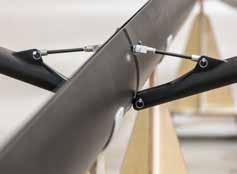


9 1a 1b 1c 2a Its important to lubricate the two halfes before pushing them togeher. 2b 3 4 5a 5b 9
10 VERY IMPORTANT! It is VERY IMPORTANT that the clevis pin is orientated with the head facing towards the trailing edge of the mast and the key ring is towards the leading edge of the mast. The shrouds can be damaged and the mast can fall down if the clevis pin is orientated the wrong way. 7 8 How to check the spreader angle: Pull a string tight between the center of the spreader tips and measure the distance between the string and the trailing edge of the mast at the joint. Standard measurement is 190mm, minimum is 180mm and maximum is 200mm. Larger spreader angle will give more mast prebend. The adjusted length of the spreader turnbuckles must be the same on both sides. A halft turn on turnbuckles gives approximately a 5mm change in spreader angle. As shown in picture 7a the string should be pulled just above the end fitting on top of the diamond stay. Tension the diamond turnbuckle until you get your required prebend. Prebend should be a minimum of 70mm with full main and 80mm when sailing with a reef IMPORTANT! The halyards need to have a diameter of 8mm to prevent the halyards to come out through the luff track. Do not remove the cover or use lesser diameters. Remove the top sheave to insert the Main halyard. Use a small hook to pull the halyards through the luff track. Tie the sail head end of the halyards to the mast close to the mast foot. Let the Main halyard at the bottom go through the block on starboard side and up to the winch. 9 Prebend is defined in this case as the distance between the trailing edge at the spreader and an artificial straight line between the upper most point and lowest point of the trailing edge of the luff track. When measuring the prebend the mast supports shall be placed 150cm above the bottom end of the mast and one 20cm above the upper diamond stay fitting Let the Gennaker halyard at the bottom go through the spinlock on port side of the mast. The diamond tension using the Loos & Co. gauge RT-10M(3,2-7,1mm) with the base of the gauge in just above the mast winch is recommended to be in the interval If the required prebend is not reached at 55 on the gauge the spreader angle needs to be adjusted. 10


11 7a 7b 7c 8 10a 10b 12 11

12 12
13 13

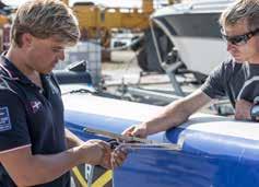
14 PLATFORM ASSEMBLY TOOLS TOOLS INCLUDED 1 Adjustable spanner 5 Socket set 2 Flat headed screw driver 6 Ring spanners 3 Allen wrench set 7 Phillips screwdriver 4 Knife 8 Torx wrench kit 14


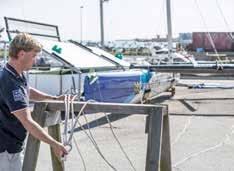
15 PLATFORM ASSEMBLY INSTRUCTIONS PLATFORM ASSEMBLY 1a 1b 1a Position the two hulls with the two beams in place. 1b Adjust the position until everything lines up before putting in the beam bolts. 15

16 VERY IMPORTANT! Put grease on the entire thread of the bolts. We recommend Rocol ANTI-SEIZE Stainless. Other marine grease for stainless should function. 2 Put in the 8 beam bolts with washer. Tighten the 8 bolts until there is no play left, there will not be a distinct stop. 5 Slide the trampoline in from the front; you need to be two persons. Be careful to not scratch the hulls with the fiberglass rods. 3 Do not over tighten the bolts, the bolts only needs to be lightly tighten but with no play left between beam and hull. Put in the 4 travel track bolts with washer from inside of cockpit. 6 Fasten the trampoline to the main and aft- beam as the illustation below shows. Tighten the net at the mainand aft- beam first then tighten the net along the sides. Tighten the 4 bolts until there is no play left, there will not be a distinct stop. Do not over tighten the bolts, the bolts only needs to be lightly tighten but with no play left between travel track and hull. 4 Position the trampoline in front of the boat with the two fibreglass rods facing forward. 16


17 2a 2b 3 3b 4 5 6a 6b 17
18 18

19 19
20 NOTE! Bowprit and racks are assembled after the stepping of the mast. The mast cannot be raised if the bowsprit is connected. 7 8a Attach the bowsprit to the main beam; lock the pin with the chock-cord. Check that the tack pilot line is in place. Attach the gennaker halyard to the middle of the bowsprit and hoist the bowsprit. Connect the bolts while holding the struts upright, do not forget to grease the threads. 10 Attach the rudder assemblies to the hulls and lock the locking arm with the shock-cord. Make sure that the stainless pin is clean so the rudder can rotate easily and that it is completely through the lower gudgeon. IMPORTANT! 8b 9 Leave about a 5mm gap when tightening the bolts. Lower the bowsprit gently and connect the struts carefully before securing with the pins. When the struts are connected the bolts can be tightened so there is no play between the strut and hull. Do not over tighten as it will damage the threads! The locking arm of the rudder shaft shall face outward. The groove in the plastic puck is deeper on the outside. If the locking arm is facing inwards then the locking arm can unlock and result in expensive repairs to the hull. The schock cord needs to be replaced regurarly to ensure that the locking arm is secured in the groove. 20


21 7 8a 8b
22 NOTE! Bowprit and racks are assembled after the stepping of the mast. The mast cannot be raised if the bowsprit is connected. 11 Connect the tiller bar to the two rudder heads. Attached with clevis pins and locked with key/lock-ring Attach the racks to the boat with bolt and nut. It s important to use lock nuts. The starbord and port racks are different. To identify which is which one can look at the foot support for sheeting that should be on the forward end of the rack. 14 Hook the tightening line to the loop on the main beam and then lash and tighten the line at aft beam. It s easier to tighten the rack-trampoline if the rack is in its upright position. 22


23 11a 11b 11c
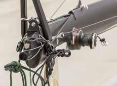
24 MAST STEPPING INSTRUCTIONS Read though the manual carefully before stepping the mast. Consult your local M32 representative if there are any further questions or if you are unsecure about the procedure. MAST STEPPING 1 2 The mast must be fully assembled including the halyards before stepping the mast. Place the T-tang in front of the boat and make sure that the forestays and shrouds are clear of each other. 5 Place the mast foot beside the mast step. Let the upper part of the mast rest on a support that prevents the mast from rotating. The mast top must be horizontal or higher than the mast step, higher is better. Secure the mast foot with a rope so it does not fall of the beam. 3 4 Lash the forestay to the chain plate. The forestays are the two that are in the centre of the T-tang. The lashing should be approximately 180mm long to ensure that the mast can pass the vertical axle and rest safely on the forestays and main halyard. The measurement is taken between the top of the stainless chainplate and the lowest inner diameter of the friction ring Lash the shrouds to the rack arm fitting or beam bolt on the main beam. It is normal with quite a bit of slack in the shrouds when the mast is in the down position Hook the T-tang(forestay/shroud fitting) to the mast. Attach the boom to the mast. Let the boom rest in front of the main beam when attached to the mast Strap the hoisting block with the hoisting line around the aft beam. The strap shall be on the starboard side of the traveler adjustment fitting if the port winch is used to hoist the mast and port side if starboard winch is used. Attach the hoisting line securely to the boom. TIP Put the furling line around the mast step straight away. 24


25 a 9b 25

26 Secure the hoisting line around the deck winch. Take the main halyard from the mast. Attach the main halyard securely to the boom. 17 Remove slack in the main halyard and hoisting line, the boom must be leaning forward to ensure that it is clear from the aft beam when the mast is upright. The main halyard and hoisting line are functioning as the aft support of the mast so this must be kept tight until the shrouds are attached to the chainplates. 13 Tighten the main halyard and secure it by two half-hitches, to the mast foot or gooseneck. Do not trust the self tailing on the winch or the blocks on the mast foot. 14 Attach the two boom support lines aft of the boom slider. It is important that the lines cannot slide inwards or off the boom. 15 Put the furling line for the gennaker around the mast step if this haven t been done already. 16 Raise the boom and attach the support lines to the rack arm fitting on the main beam, take away the slack in the lines and centre the boom. VERY IMPORTANT! Lock the mast rotation arm. The mast will fall down during the hoisting if the rotation arm is not locked in the central position. 26


27
28 Apply the supplied grease on the mast ball. Place the mast on the mast ball. Start hoisting the mast by winching the hoist line while lifting the mast top. Lock the hoisting line when the mast is resting on the forestays. Move one shroud at the time back to the chain plates and lash them lightly. If a forestay is twisted then remove the lashing and untwist the stay. Do not remove more than one stay or shroud at one time To easily measure the rake of the mast, determine the distance from the mast top to the aft beam by using the main halyard. Secure the main halyard with the knot parallel to the bottom of the lower mast tube. While keeping tension in the halyard use a folding rule to take a measurement. Measure from the aft radius of the aft beam to the knot on the halyard. A reference point can be added to the aft beam. 480mm is used as a base setting for the rake. IMPORTANT! 22 When the shrouds are fastened and the mast is secure the hoisting line can be removed and the main sheet can be connected. After the rake is set and shrouds and forestays are tightened a tight shock cord shall be put between the forestays to remove the slack and ensure that the forestay does not get caught behind the spreader while manuevering. WHEN HOISTING THE MAST / KEEP AN EYE ON Check that the mastfoot is positioned correctly on the mast step. Be careful not to get an override on the hoisting winch. An override preventer can be used on the trampoline. The mast rotation arm, the control line can tighten during the hoisting. Loosen the control line a little bit if this happen. The boom support line and shrouds can also tighten during the hoisting. Loosen them a little bit if this happen. Do not stand directly underneath the mast while hoisting or lowering the mast. Check that nothing gets stuck. Make sure to steer the mast on the way up with the forestays. When the mast is almost upright, let it gently fall back into a position where it rests on the forestays and the main halyard until the shrouds have been fastened. It is very important that the shrouds and forestays are placed in such way that they cannot get stuck or damage during the mast stepping. Consult your local M32 representative before hoisting the mast if there are any further questions or if you are unsecure about the procedure. 28


29
30 MAIN HALYARD LOCK INSTRUCTIONS MAIN HALYARD LOCK 1 The halyard lock consists of a carbon fiber traveler, a steel locking arm and a spring. 6 Unhook the loop from the locking arm when removing the Main halyard, do not untie the knot The main halyard is connected to the halyard lock via a short Dyneema loop. The sail is hooked to the locking arm via a longer Dyneema loop. Both loops hang on the same spot on the locking arm. The Main halyard is tied to the smaller loop with a half hitch and secured with a stop knot. 7 BEFORE HOISTING THE MAIN: Check that the spring has enough tension to pull the locking arm fully down into locking position. Pull back the locking arm and slide the assembly into the luff track. Hook the Main halyard to the locking arm. The stop knot MUST face away from the mast. Hook the Main sail to the locking arm. IMPORTANT! It s IMPORTANT that the stop knot always faces away from the mast otherwise the halyard lock WILL NOT FUNCTION. 30


31 1 2 4! 31
32 IMPORTANT! Make sure that the steel locking arm is all the way down into the groove when locked. Do not connect the cunningham or boom if this is not the case as it is not designed to take the load unless the steel locking arm is all the way into the groove. 8 HOW TO LOCK IN UPPER POSITION: a. Hoist the Main all the way to the top. No winch should be needed if the mainsail track is clean. b. Twist the rotation arm to get some friction so that the sail goes gently into the lock. c. Push the sail upward at the bottom and at same time release the Main halyard completely (The halyard needs to be completely slack all the way for the lock to function). d. See to that the mast and sail is aligned and pointing straight into the wind. Slowly pull down the sail until it locks. The lock will not function if the sail is pull down to fast or if there is any tension in the halyard. 9 TO UNHOOK MAIN HALYARD LOCK: Simply hoist the sail a little bit and then pull down the sail with some tension in the halyard until the lock has travelled past the cut out in the mast. (Tension in sail and halyard equals opening the lock. No tension in halyard equals locking position.) The halyard is locked when the locking arm is in the one of the cut outs in the mast and NO tension in the halyard. IMPORTANT! Before fastening the boom, a strop should be fastened around the mast through the cunningham ring tight to the mast. This is done to prevent the ballrope from exiting the track. 32


33 HOW TO LOCK AT REEF POINTS: IF THE LOCK DOES NOT LOCK: Hoist or lower the sail to a position just above reefing point, then slowly pull down the sail without any tension in the halyard until the halyard locks. To unhook simply hoist the sail a little bit and then pull down the sail with some tension in the halyard until the lock has travelled past the cut out in the mast. Tip: If you pull down the sail fast past the reef points the main halyard will not lock. Check that the stop knot is facing away from the mast. Check that the halyard is slack all the way. Check that the sail is hoisted beyond the locking position. Check that the spring has enough tension. Check that the small loop connecting halyard and lock has the correct length. The inner measurement of a flatten loop shall be between 11-12cm. 8a 8b 8c 8d 33
34 34 NOTES
35 NOTES 35
36 36
Table of content Introduction 5 1. Part 1. Assembly Tools needed for Assembly Glossary Hulls Mounting the beams 7
 Table of content Introduction 5 1. Part 1. Assembly 6 1.1. Tools needed for Assembly 6 1.2. Glossary 6 1.3. Hulls 7 1.3.1. Mounting the beams 7 1.3.2. Fixing the mast rotation cleats 8 1.3.3. Placing the
ASSEMBLY MANUAL HOBIE CATSY
 ASSEMBLY MANUAL HOBIE CATSY HOBIE CAT EUROPE ZI Toulon Est, BP 50 8078 Toulon cedex 9, France Tel : + (0)9 08 78 78 - Fax : + (0)9 08 99 Email : hobiecat@hobie-cat.net - http://www.hobie-cat.net ASSEMBLY
Index 1. Trampoline 2. Main Foils 3. Spinnaker Pole 4. Mast Setup 5. Mast Rigging 6. Rig Tension 7. Trapeze Lines 8. Rudders 9. Boom 10. Main Sheet an
 By User Manual Index 1. Trampoline 2. Main Foils 3. Spinnaker Pole 4. Mast Setup 5. Mast Rigging 6. Rig Tension 7. Trapeze Lines 8. Rudders 9. Boom 10. Main Sheet and Traveler 11. Main Sail 12. Downhaul
FDR CHRYSLER 16' CATAMARAN (MUSKETEER) The initial rigging of a sailboat is not difficult, but if the boat is strange
 The initial rigging of a sailboat is not difficult, but if the boat is strange") Page of 6 Revised 2/0/76 RIGGING INSTRUCTIONS FDR CHRYSLER 6' CATAMARAN (MUSKETEER) The initial rigging of a sailboat is not difficult, but if the boat is strange to the new owner, or the new owner is
Page of 6 Revised 2/0/76 RIGGING INSTRUCTIONS FDR CHRYSLER 6' CATAMARAN (MUSKETEER) The initial rigging of a sailboat is not difficult, but if the boat is strange to the new owner, or the new owner is
Topaz OMEGA Rigging Instructions
 Topaz OMEGA Rigging Instructions www.toppersailboats.com TOPAZ OMEGA RIGGING INSTRUCTIONS CONTENTS 02. Introduction 02. Manufacturers Details 03. Maintenance 04. Raising the Mast 05. Attaching the Boom
2. Note that the ropes from the rigging board are secured in the cam cleats of the jib fairleads.
 VII 1. Place the hull, bow into wind, on its trailer, a soft surface, or a rigging board. We strongly recommend making a rigging board; it is simple and inexpensive and greatly simplifies rigging and working
 Table of content Introduction 5 1. Part 1. Assembly 6 1.1. Tools needed for Assembly 6 1.2. Glossary 6 1.3. Hulls 7 1.3.1. Mounting the beams 7 1.3.2. Fixing the mast rotation cleats 8 1.3.3. Mounting
Bladerider X8 Assembly Help Notes
 2.1 Remove All Parts & Have Some Tools Handy Remove all items from the box and identify each part as per the packing sheet and check that nothing is missing. If there is something missing, please email
Pico rigging manual 2007.doc Page 1 of 28
 Pico rigging manual 2007.doc Page 1 of 28 Pico Rigging Instructions The Pico rigging instructions are a guide to rigging your boat. Due to production supplies certain parts may be slightly modified from
TUNE YOUR SAILS SPEED
 TUNE YOUR SAILS FOR OUTRIGHT SPEED Rev R05 Important Notes l We recommend not exceeding 350lbs total crew weight as this puts excess stress on the mast and the boat. l When sailing, the boat performs best
Ref :MMHC14SR_GB Emetteur :MF Date :Dec 2014 Revision : 1 Page 1/18. ASSEMBLY MANUAL : HOBIE CAT 14 Std & Race HOBIE CAT 14 STD & RACE
 Ref :MMHC14SR_GB Emetteur :MF Date :Dec 2014 Revision : 1 Page 1/18 HOBIE CAT 14 STD & RACE Ref :MMHC14SR_GB Emetteur :MF Date :Dec 2014 Revision : 1 Page 2/18 TABLE OF CONTENT Part list... 3 Ropes and
Essential Rig Tuning Guide The Ins and Outs of tuning your mast.
 Essential Rig Tuning Guide The Ins and Outs of tuning your mast. Tuning Your Rig The main goal in tuning your mast is to achieve a spar that s straight. By doing this it will help you gain control of sail
J/70 Building Specification
 DECK, HARDWARE AND FITTINGS 1 FRP Composite deck 2 Indeck furler unit 3 Bow "U" bolt mooring eye (stainless) Option for one 6" (152mm) mooring cleat in lieu of eye. 4 Shroud chainplates (stainless) (BSI
F-27 RIGGING GUIDE EXTRACTED FROM ORIGINAL F-27 SAILING MANUAL
 F-27 RIGGING GUIDE EXTRACTED FROM ORIGINAL F-27 SAILING MANUAL By Ian Farrier not be possible if the towing vehicle is a van. When trailering, allow extra distance for stopping. Watch also for low bridges,
RIGGING INSTRUCTIONS Let's assume that you have your boat on a trailer when you take delivery from your dealer.
 This is the original owner's manual, written about 1972, and applicable for boats manufactured through 1978. Starting in 1979 a few changes were made in the roller furling jib and forestay arrangement.
ASSEMBLY MANUAL. Last up-date : January 2005 HOBIE MAX RACE
 ASSEMBLY MANUAL Last up-date : January 005 HOBIE MAX RACE List of the parts Necessary tools spanners nr 7 It is advisable to be at least two people to assemble the Hobie Max pair of niversal pliers TABLE
Wysiwig - Wayfarer Rigging Guide
 Wysiwig - Wayfarer 8767 - Rigging Guide GENERAL NOTES Before you go afloat, make sure that the self-bailer is closed. It is operated through the cut-out in the starboard floorboard. If you do not close
Club 420 Class Rigging Manual
 Club 420 Class Rigging Manual Performance sailcraft 2000 Inc 2555 Dollard Lasalle, Quebec, H8N 3A9 Tel: 514 363 5050 email: info @ps2000.ca Website: www.ps2000.ca Mast set up Remove the pole and unwrap
Weta Basic Rigging Guide
 Weta Basic Rigging Guide A quick reference guide of how to rig your Weta, with some tips to make rigging quick and easy! For a more indepth guide see our Weta Manual under Weta Owners on the website. 1.
COASTAL IN-BOOM FURLING SYSTEM. Installation Manual
 COASTAL IN-BOOM FURLING SYSTEM Installation Manual 1 TABLE OF CONTENTS Page Number 3. Disclaimer 4. Components packing list & required tools 5. Gooseneck bracket location 6. Installation sail track 7.
Follow these easy steps to properly assemble your new Zim 420
 Thank you for buying a Zim 420 and welcome to the Zim Sailing family. We are extremely proud of the quality of our boats and the race results are proven. Many of the top sailors are choosing Zim over other
OWNER S MANUAL. for Inters and Nacra F-18
 OWNER S MANUAL for Inters and Nacra F-18 Tools you ll need: 9/16 socket Wrench Phillips Screwdriver Allen Wrench (included) HULL ASSEMBLY Place hulls boxes approx. 8 feet apart. Make sure both hulls are
Tuning Guide January 2012
 Tuning Guide January 2012 www.skud.org This tuning guide has been prepared by the IACA SKUD 18 Committee to assist new sailors in the SKUD 18 class to prepare their MkI or MkII boat to a competitive level
HOBIE TEDDY ASSEMBLY MANUAL
 ASSEMBLY MANUAL HOBIE TEDDY HOBIE CAT EUROPE ZI Toulon Est, BP 50 83078 Toulon cedex 9, France Tel : +33 (0)494 08 78 78 - Fax : +33 (0)494 08 3 99 Email : info@hobie-cat.net - http://www.hobie-cat.net
1 Tuning Platform Reseating Beam Pads Rudder alignment Noisy Foils Rig Tension...
 Contents 1 Tuning... 2 1.1 Platform... 2 1.2 Reseating Beam Pads... 2 1.3 Rudder alignment... 3 1.4 Noisy Foils... 3 1.5 Rig Tension... 4 1.6 Mast rake... 4 1.7 Spreader rake... 5 1.8 Diamond tension...
OWNER S MANUAL OWNER'S MANUAL TABLE OF CONTENT. 1. Introduction. 2. EC Documentation a) Certificate of homologation b) Declaration of conformity
 Certificate of homologation b) Declaration of conformity") OWNER'S MANUAL TABLE OF CONTENT 1. Introduction 2. EC Documentation a) Certificate of homologation b) Declaration of conformity 3. Description a) Hull identification b) Design category c) Technical data
OWNER'S MANUAL TABLE OF CONTENT 1. Introduction 2. EC Documentation a) Certificate of homologation b) Declaration of conformity 3. Description a) Hull identification b) Design category c) Technical data
A Basic Guide to Europe Dinghy Rigging
 The Basics: A Basic Guide to Europe Dinghy Rigging Use the smallest blocks available for the line size. Most of the blocks on your boat will be micro blocks. Examine all of your rigging and ensure that
CONTENTS. SB 3 Rigging Instructions
 RIGGING MANUAL SB 3 Rigging Instructions The Laser SB 3 rigging instructions are a guide to rigging your boat. Due to production supplies certain parts may be slightly modified from those shown. This instruction
2012-June-12 SECOND DRAFT Hobie Getaway Spinnaker Installation Instructions
 SECTION A: INTRODUCTION This unofficial set of installation instructions was written for a 2009 Hobie Getaway, using a 2012 Hobie Spinnaker Kit 20999020. Note from the Author: I had never seen this kit
Wind Light Moderate Heavy Speed 0-8 mph 9-17 mph 18 + mph
 Hobie 20 Racing Setting - Compiled by Bob Mimlitch, Fleet 23, Dallas, TX Most of the information is from Bob Curry's articles in Catamaran Sailor published by Mary Wells. Wind Light Moderate Heavy Speed
Vanguard Sailboats 300 Highpoint Avenue Portsmouth, RI For the dealer nearest you call SAIL
 Vanguard Sailboats 300 Highpoint Avenue Portsmouth, RI 02871 For the dealer nearest you call 800. 966.SAIL Unpack the major parts listed below and lay them out on a soft piece of ground free of sharp objects.
CII Rigging suggestions
 CII Rigging suggestions This mini-manual uses photographs of the final prototype sail and the final pre-production mast. Where changes occurred between these and the production units, they are described
TUNE YOUR SAILS SPEED. Optimist Tuning Guide. Photo Wavelength
 TUNE YOUR SAILS FOR OUTRIGHT SPEED Photo Wavelength PEAK / HEAD THROAT TACK CLEW THANK YOU for choosing North Sails for your Optimist. Whether you are just starting out in an Optimist you are an experienced
HOBIE CAT 16 Easy, Classic, Club & Race
 ASSEMBLY MANUAL HOBIE CAT 6 Photo Pierrick Contin Last Update : January 008 HOBIE CAT 6 Easy, Classic, Club & Race HOBIE CAT EUROPE ZI Toulon Est, BP 50 83078 Toulon cedex 9, France Tel : +33 (0)494 08
INSTRUCTION NO
 INSTRUCTION NO. 14138 Dagger Rigging Instr. P~e 2.of 6 MODEL 244 CHRYSLER "DAGGER" SAILBOAT RIGGING INSTRUCTIONS We, at Chrysler Boat Corporation, congratulate you on your selection of our Model 244 "Dagger"
North Sails Seattle Thunderbird Tuning Guide
 Page 1 of 6 North Sails Seattle Thunderbird Tuning Guide Introduction The following tuning guide is meant as a good starting point in setting up your boat. Since not all Thunderbirds are exactly alike
Safety Afloat. Before you go sailing:
 RIGGING MANUAL Safety Afloat This instruction manual is not a guide to sailing your craft and it should not be considered suitable for the task of learning to sail a boat. Please read the manual before
12.9 Gennaker. February Setting up and sailing with the 12.9 Gennaker
 12.9 Gennaker Setting up and sailing with the 12.9 Gennaker February 2013 The 12.9 Gennaker is a new bigger gennaker for the Weta. The standard gennaker is 8 sqm and the 12.9 gennaker is 12.9 sqm. The
WELCOME TO THE HOBIE FAMILY
 ASSEMBLY MANUAL WELCOME TO THE HOBIE FAMILY Congratulations on the purchase of your new TriFoiler and welcome to the HOBIE sailing family. We offer this manual as a guide to increased safety and enjoyment
Set-up and Tuning Notes: 17 September 2012
 Set-up and Tuning Notes: 17 September 2012 This document is being continually updated. Please check the release date above regularly to ensure you have the most recent edition. We appreciate any feedback
Dolly wheels in slot #8 for Boat #10.
 Rigging: Laser SAIL SELECTION: The International Laser Class has three different official rigs. Each sail is designed for sailors of different weights. The Standard Rig was designed for sailors weighing
OPPI Rigging Guide 3/2008
 OPPI Rigging Guide 3/2008 McLaughlin Boat Works optistuff.com Thanks for purchasing OPPI, the most durable and F-U-N sailboat available. Rigging your OPPI is easy and the following pictures make it a breeze
TUNE YOUR SAILS FOR OUTRIGHT SPEED. Starling Tuning Guide Solutions for today s sailors
 1 TUNE YOUR SAILS FOR OUTRIGHT SPEED 1 The object of the Starling class is for all sails and masts to be identical. We pride ourselves on our ability to reproduce sails identically, so please feel free
Sanibel Owners Manual
 Sanibel 36-600 Owners Manual TM Specifications Length (Hull):... 36 inches Height (Mast):... 51.5 inches Height (Overall):... 69 inches Beam:... 7.5 inches Radio: JR Beat Gear w/sail winch servo Sail area:
HOW TO RIG A CORMORANT
 HOW TO RIG A CORMORANT Page 1 of 6 Instructions adapted from Cormorant Owner s Handbook 1 Ensure that peak halyard, throat halyard and topping lift are attached to the mast as shown in Fig. 1. 2 Set-up
Symptom: The basic symptom is your sail will not roll in or out without force. The drum unit is hard to turn. Your sail will not roll out on its own.
 Schaefer 2100 roller furler drum replacement on Catalina 320 Danny Jensen, A BOA VIDA hull #972, Thanks to contributions Chris Burti, Jeff Hare and C320 group for comments Photos were taken and edited
PT 11 trouble-shooting and maintenance.
 PT 11 trouble-shooting and maintenance. Does your rudder not stay down?...your back seat slip off?...your knobs tight and your leather pads loose? Maybe we can help. We have used our PT 11 s hard enough
Rudder Kit Assembly Instructions for Quest 13
 Rudder Kit Assembly Instructions for Quest 13 Revised 4/2/2015 78501 Rudder System The Hobie Quest is designed for the addition of an optional rudder system. Rudder systems in boats like this allow you
Fitting Instructions For Slab Reefing Kit Part No For Yachts Up To 8.5m (2 Reefing Points)
") Fitting Instructions For Slab Reefing Kit Part No 41483 For Yachts Up To 8.5m (2 Reefing Points) This system makes reefing your mainsail a quick and easy operation. Just lower the mainsail just below a
Fitting Instructions For Slab Reefing Kit Part No 41483 For Yachts Up To 8.5m (2 Reefing Points) This system makes reefing your mainsail a quick and easy operation. Just lower the mainsail just below a
Y-FLYER TUNING GUIDE ONSHORE ADJUSTMENTS
 Y-FLYER TUNING GUIDE Congratulations on your purchase of North Y-Flyer sails. We are confident you will find superior speed over all conditions. Your sails are designed to be fast, as well as easy to trim
TUNE YOUR SAILS FOR OUTRIGHT SPEED. Melges 20 Tuning Guide. Rev R05
 TUNE YOUR SAILS FOR OUTRIGHT SPEED The following tuning guide is meant to be a good starting point when setting up your Melges 20. Depending on total crew weight, wind and sea condition and sailing style
HOBIE TEDDY ASSEMBLY MANUAL
 ASSEMBLY MANUAL HOBIE TEDDY HOBIE CAT EUROPE ZI Toulon Est, BP 50 83078 Toulon cedex 9, France Tel : +33 (0)494 08 78 78 - Fax : +33 (0)494 08 3 99 Email : info@hobie-cat.net - http://www.hobie-cat.net
SHIELDS PARTS PRICE SHEET
 7 Narrows Road * P.O. Box 152 * Wareham, MA 02571-0152 * Phone (508) 295-3550 * Fax (508) 295-3551 www.capecodshipbuilding.com * info@capecodshipbuilding.com SHIELDS PARTS PRICE SHEET Part Number DESCRIPTION
TUNE YOUR SAILS SPEED. Etchells Tuning Guide. Rev Q04
 TUNE YOUR SAILS FOR OUTRIGHT SPEED Congratulation on your purchase of North One Design Etchells sails. The following tuning guide is meant to be a good starting point in setting your Etchells rig and sails.
TUNE YOUR SAILS FOR OUTRIGHT SPEED. E Scow Tuning Guide Rev Q10 Photo David Thoreson
 TUNE YOUR SAILS FOR OUTRIGHT SPEED Photo David Thoreson Knowledge is power. We see this in every sport throughout the world. Racing sailboats is much different from the other sporting events. Sailing requires
E Manual Self tacking system 30
 597-205-E 2015-12-09 Manual Self tacking system 30 1 Self tacking system 30, 443-200-10 A self-tacking jib makes life on board a lot easier, in particular for shorthanded crews. The jib sheet is led to
VERSA BIKE RACK INSTRUCTIONS
 VERSA BIKE RACK INSTRUCTIONS Models #8, 8 Important This rack is designed for use with a or. receiver hitch. The rack is designed to hold a maximum of two bicycles. Do not use it for anything other than
OPERATIONAL CHECK LIST
 www.spinnakersailing.com (650) 363-1390 OPERATIONAL CHECK LIST https://twitter.com/#!/spinnakersailin http://www.facebook.com/spinnakersailingrwc http://www.spinnakersailing.com/newsletter.html Dear Sailor,
Parts List. 7. Handlebars 8. Grips 9. Handlebar Stem 10. Front Brake 11. Front Wheel 12. Crank 13. Chain
 Woodworm Cruise Parts List 1. Free Wheel with Rear Hub 2. Fenders 3. Fender Stay 4. Quick Release 5. Saddle 6. Seat Post 7. Handlebars 8. Grips 9. Handlebar Stem 10. Front Brake 11. Front Wheel 12. Crank
Below are the instructions to build a roller-furling unit for under $10. Read the entire process before beginning the project.
 Greg Cowens' $10 PVC Roller Reefing for CP-16's by Greg Cowen Below are the instructions to build a roller-furling unit for under $10. Read the entire process before beginning the project. Materials: 2
In each step, the needed parts are shown the number right below. Locate all parts for the step.
 Tools Required for Assembly Phillips Screwdriver, Med Needle Nose Pliers Sandpaper (#400 grit) Hobby Knife Scissors CA Instant Glue Rubbing Alcohol Drill Bit 1/16", 1.6mm 5/64, 2mm 1/8, 3mm 5/32, 4mm Before
QuikVang. The Original High-Performance Vang INSTALLATION AND OPERATING INSTRUCTIONS MODEL D-30 MODEL D-40
 QuikVang The Original High-Performance Vang INSTALLATION AND OPERATING INSTRUCTIONS MODEL D-30 MODEL D-40 33 Broadcommon Road, Bristol, RI 02809 USA T: 401.253.4858 F: 401.253.2552 www.hallspars.com 1
Schaefer recognized this issue and they offer to replace the drum bearing assembly for $
 Schaefer 2100 roller furler drum replacement on Catalina 320 Danny Jensen, A BOA VIDA hull #972, Thanks to contributions Chris Burti, Jeff Hare and C320 group for comments Photos were taken and edited
TUNE YOUR SAILS SPEED
 TUNE YOUR SAILS FOR OUTRIGHT SPEED J/70 Tuning Guide Rev. R02 After countless hours sailing, testing and competing in the J/70 One Design, North Sails has updated our tuning notes and tips in an effort
Daysailer Tuning Guide
 Daysailer Photo Deb McCaffrey For any question you may have on tuning your Daysailer for speed, contact our experts: Brian Hayes 203-783-4238 brian.hayes@northsails.com Chris Snow 619-226-1415 chris.snow@northsails.com
RIGGING: RS- Vision. 1. A properly derigged boat appears as below. Please note that the tiller extension is NOT bent.
 RIGGING: RS- Vision The RS- Visions should be rigged on the floating dock or on its trailer then put into the water. While rigging, carefully inspect the vessel and equipment to make sure everything is
TUNE YOUR SAILS SPEED. J/70 Tuning Guide Rev. Q10a. Photo Chris Howell
 TUNE SAILS FOR OUTRIGHT SPEED J/70 Tuning Guide Rev. Q10a Photo Chris Howell After countless hours sailing, testing and competing in the J/70 One Design, North Sails has updated our tuning notes and tips
Instruction Manual. Features. Specification: Length: 730mm Width: 500mm Height: 1000mm Sail Area: 0.15m 2. Weight: 692g (w/o battery & receiver)
") AN UNBELIEVABLE SPEED MACHINE Instruction Manual Features Specification: Length: 730mm Width: 500mm Height: 1000mm Sail Area: 0.15m 2 Weight: 692g (w/o battery & receiver) Thank you for purchasing your
AN UNBELIEVABLE SPEED MACHINE Instruction Manual Features Specification: Length: 730mm Width: 500mm Height: 1000mm Sail Area: 0.15m 2 Weight: 692g (w/o battery & receiver) Thank you for purchasing your
Stand-N-Fish FULL DETAIL INSTALLATION INSTRUCTIONS
 1 Stand-N-Fish FULL DETAIL INSTALLATION INSTRUCTIONS Thank you for purchasing the incredible new Stand-N-Fish Kayak Fishing System. Once installed on your kayak the Stand-N-Fish will take your kayak fishing
Rhodes 19 Tuning Guide
 Rhodes 19 Tuning Guide Jud Smith jsmith@doylesails Tomas Hornos tomas@doylesails.com Send order forms to: onedesign@doylesails..com SETTING UP YOUR RHODES 19 FOR DOYLE SAILS BEFORE STEPPING THE MAST 1.
CONTENTS INTRODUCTION
 INTRODUCTION This owner s manual is provided to ease assembly, maintenance and use of your Prindle Catamaran. We believe these instructions portray the simplest methods. Do it our way the first time and
Owner s Manual. Revision Date: Copyright 2012 Falcon Marine LLC 9008 Marlin St. Cape Canaveral, FL USA
 Owner s Manual Revision Date: 2013-02-06 Copyright 2012 Falcon Marine LLC 9008 Marlin St. Cape Canaveral, FL 32920 USA 321-799-4841 Falcon Marine LLC Falcon Marine LLC Falcon F18 This manual covers the
Laser Rigging Basics St. Jamestown Sailing Club
 Laser Rigging Basics St. Jamestown Sailing Club This rigging guide is intended as a reference of Laser rigging best practices. It is not a substitute for personal instruction and you should attend a Laser
TUNE YOUR SAILS SPEED. Viper 640 Tuning Guide. Rev. R03b
 TUNE YOUR SAILS FOR OUTRIGHT SPEED Mast Tuning Tuning Guide for the Carbon Mast SET SPREADER ANGLE Check spreader angle by placing a straightedge or string from shroud to shroud at the spreaders. Measure
DOYLE Cradle Cover MANUAL
 DOYLE Cradle Cover MANUAL The Doyle Cradle Cover Upon receiving your new Doyle Cradle Cover and before starting actual installation, we recommend laying out your Cradle Cover on a hard surface in a secure
Far East Boat Optimist Rigging Instructions
 Far East Boat Optimist Rigging Instructions These instructions are written specifically for Far East Boats Championship and Racing Optimist. Parts of the Optimist PAGE 1 Sprit Wind Indicator Sail Mast
PROFURL IN-BOOM REEFING SYSTEM MK 3 R SERIAL NUMBER :... INSTALLATION MANUAL
 13/09/13 I P142GB13D MK 3R PROFURL IN-BOOM REEFING SYSTEM MK 3 R SERIAL NUMBER :... INSTALLATION MANUAL IMPORTANT NOTICE TO RIGGERS : PLEASE GIVE THIS MANUAL TO THE BOAT OWNER AND ASK HIM (HER) TO CAREFULLY
STANDARD SPECIFICATIONS
 STANDARD & OPTIONS SPECIFICATIONS January 2018 STANDARD SPECIFICATIONS TECHNICAL DATA Length: 5,55 m Width: 2,38 m Light displacement: 500 kg Mainsail area: 14,5 m2 Jib area: 9,2 m2 Gennaker area: 32 m2
Trogear Bowsprit Through Hull Installation Manual
 Trogear Marine Products, LLC www.trogear.com info@trogear.com 866-616-2978 Trogear Bowsprit Through Hull Installation Manual Congratulations on your purchase of the Trogear Bowsprit which can be installed
Hansa 2.3 Rigging Guide
 Hansa 2.3 Rigging Guide Manufactured by Hansa Sailing Systems Pty Ltd ABN 56 079 318 031 4/4 Cumberland Avenue SOUTH NOWRA NSW 2541 AUSTRALIA Postal: PO Box 5048 NOWRA DC NSW 2541 Telephone: +61 2 4403
APP pumps APP and APP Disassembling and assembling
 Service guide APP pumps APP 11-13 and APP 16-22 Disassembling and assembling hpp.danfoss.com Table of Contents Contents 1. Introduction... 2 2. Disassembling the pump... 3 3. Assembling the pump... 6 4.
Mast Assembly Manual. for
 Mast Assembly Manual for J 44 Hall Spars 1 Introduction MAST ASSEMBLY MANUAL Welcome to the Hall Spars owners family. Our spars are designed for strength, function, and reliability. Please read this assembly
Fitting Instructions for Single Line Mainsail Reefing System For Yachts Up To 9m (30ft) - Part No
 - Part No") Fitting Instructions for Single Line Mainsail Reefing System For Yachts Up To 9m (30ft) - Part No. 41 130 This single line reefing kit allows reefing control lines to be led aft to the safety of the cockpit.
Fitting Instructions for Single Line Mainsail Reefing System For Yachts Up To 9m (30ft) - Part No. 41 130 This single line reefing kit allows reefing control lines to be led aft to the safety of the cockpit.
INTERNATIONAL SUNFISH CLASS ORGANIZATION CLASS RULES
 INTERNATIONAL SUNFISH CLASS ORGANIZATION November 2017 CLASS RULES 1. GENERAL The design and development of the Sunfish sailboat was directed to the creation of a one-design class where the true test is
QuikVang. The Original High-Performance Vang INSTALLATION AND OPERATING INSTRUCTIONS MODEL A-8 MODEL A-12
 QuikVang The Original High-Performance Vang INSTALLATION AND OPERATING INSTRUCTIONS MODEL A-8 MODEL A-12 33 Broadcommon Road, Bristol, RI 02809 USA T: 401.253.4858 F: 401.253.2552 www.hallspars.com 1 INTRODUCTION
International J/24 Class Rules Changes As approved by ISAF Effective 1 st April 2013
 Class Rule 3.2.5 International J/24 Class 2012-13 Rules Changes As approved by ISAF Effective 1 st April 2013 The deck shall be fitted with two stanchions on each side, port and starboard, as detailed
PROFURL IN-BOOM REEFING SYSTEM MK 2 R SERIAL NUMBER :... INSTALLATION MANUAL
 08/07/13 P140GB13 C MK 2R PROFURL IN-BOOM REEFING SYSTEM MK 2 R SERIAL NUMBER :... INSTALLATION MANUAL IMPORTANT NOTICE TO RIGGERS : PLEASE GIVE THIS MANUAL TO THE BOAT OWNER AND ASK HIM (HER) TO CAREFULLY
RUDDER KIT INSTRUCTIONS
 A I N S T R U C T I O N S RUDDER KIT INSTRUCTIONS TARPON 0/40/60/60i The Tarpon series is designed as a high performance sit-on-top kayak tailored for the sport paddler. Our rudder system is designed to
TUNE YOUR SAILS SPEED. J/80 Tuning Guide. Rev R12a
 TUNE YOUR SAILS FOR OUTRIGHT SPEED J/80 Tuning Guide Rev R12a This Tuning Guide was written to help you get the most performance out of your J/80. North Sails has been sailing J/80s since they were first
Contents 1. Components Introduction Preparation Hull Foredeck Mast Boom...
 Rigging Manual V5 Contents 1. Components...1-6 1.1 - Spars...1 1.2 - Rudder pack...1 1.3 - Rigging pack... 2 1.4 - Rope pack... 3 1.5 - Asymmetrical spinnaker pack... 4 1.6 - Symmetrical spinnaker pack...
BEFORE YOU BEGIN TO READ THE WI BEFORE YOU BEGIN TO READ THE WA BEGIN BY READING THIS RIGGING GU
 BEFORE YOU BEGIN TO READ THE WI BEFORE YOU BEGIN TO READ THE WA BEGIN BY READING THIS RIGGING GU Nomad Rigging Guide uide to better familiarize yourself with the parts and rigging of. If you have any questions
Disassembling and assembling APP and APP 16-22
 MAKING MODERN LIVING POSSIBLE Instruction Disassembling and assembling APP 11-13 and APP 16-22 ro-solutions.com Table of Contents 1. Disassembling...3 2. Disassembling the pump...3 3. Assembling the pump....7
ODOM CLASS SPECIFICATIONS
 ODOM CLASS SPECIFICATIONS Effective March 1, 2004 1. GENERAL 1.1 Purpose of the Measurement Rules 1.1.1 The ODOM is a One-Design Class as defined by the American Model Yachting Association (AMYA). However,
420 Rigging Guide.
 A smaller version of the olympic 470 class, the 420 was formerly a youth development class. It has a good class following, and is a good introduction to performance boats. With a PY number of 1087 it s
Rigging Manual. 1 Parts of the Hull. 2 Parts of the Sail. 3 Sunfish Mast Kit. 4 Bailer Installation. 5 Ratchet Block Installation
 SUNFISH SUNFISH RACE SUNFISH Rigging Manual 1 Parts of the Hull Go-fast tip number one: Read this rigging guide first. 2 Parts of the Sail 3 Sunfish Mast Kit 4 Bailer Installation 5 Ratchet Block Installation
Setup &Tuning guide. Updated 1st February 07
 Setup &Tuning guide Updated 1st February 07 Boat preparation Tape a piece of batten to the backstay ram with a calibrated scale drawn on it. This will allow you to reproduce the same backstay settings
Tuning C420 Sails By Brian Doyle and Dave Kirkpatrick
 Tuning C420 Sails By Brian Doyle and Dave Kirkpatrick In the spring of 2003, the Club 420 Class sails were redesigned to provide a better competitive and useful lifespan. Now that several events have been
FITTING INSTRUCTIONS FOR CASCADE LIGHTWEIGHT LAZY JACK KITS For yachts up to 10.5m (35ft) Part No
 Part No") FITTING INSTRUCTIONS FOR CASCADE LIGHTWEIGHT LAZY JACK KITS For yachts up to 10.5m (35ft) Part No. 41 143 The lightweight Lazy Jack System allows the mainsail to be easily reefed or stowed in all weather
FITTING INSTRUCTIONS FOR CASCADE LIGHTWEIGHT LAZY JACK KITS For yachts up to 10.5m (35ft) Part No. 41 143 The lightweight Lazy Jack System allows the mainsail to be easily reefed or stowed in all weather
An Australian Classic by spectre.com
 An Australian Classic by www.go spectre.com Your Bug! Welcome to the Balain Bug experience!!!!!! The Bug kit has been designed so as to be a modern version of the Traditional Bug now you can sail like
Carbo Racing Foil Instruction Manual Unit 0, 1, 2, 3
 Carbo Racing Foil Instruction Manual Unit 0, 1, 2, 3 WARNING!: Strictly follow all instructions to avoid an accident, damage to your vessel, personal injury or death. See www.harken.com/manuals for additional