Operation and Maintenance Manual for the Electric Gasmizer Diver Gas Recovery System
|
|
|
- Aubrie Ellis
- 5 years ago
- Views:
Transcription

1 OM002 Operation and Maintenance Manual for the Electric Gasmizer Diver Gas Recovery System Part Number: A10621 Document Number: P1805-OM-307 Revision: 9 P1805-OM-307 R9
2 (Intentionally Blank)
3 APPROVAL SHEET Document Information Manual No Advitium No Title Classification Current Revision Date OM002 P1805-OM-307 Electric Gasmizer Diver Gas Recovery System Commercial in confidence 9 01/12/2015 Revision History Rev Date BY CHK APP Comments 5 30/01/2009 E. Clarke J. Massie J. Massie ECN: /12/2009 D. Allan E. Aitken R. Wylie ECN: /02/2012 D. Allan A. Naylor M. Stevens ECN: /04/2015 J. Lastakauskiene A. Naylor S. Coull ECN: /12/2015 J. Lastakauskiene A. Naylor P. Black ECN: Original Approvals Responsibility Name Position Date Author Emma Clarke Administrator January 2009 Checked Jamie Massie Senior Engineer January 2009 Approval Jamie Massie Senior Engineer January 2009 Copyright Details 2015 JFD Copyright of this document is the property of JFD and it may not be copied, used or otherwise disclosed in whole or in part except with prior written permission from JFD or, if this document has been furnished under a contract with another party, as expressly authorised under that contract. OM002 P1805-OM-307 R9 i Approval Sheet
4 (Intentionally Blank) ii Approval Sheet OM002 P1805-OM-307 R9
5 DISCLAIMER Although the Gasmizer system will function correctly with a wide range of helmet/demand regulator/ exhaust regulator combinations, any specific claim Divex Ltd makes to the performance of the system assumes that a Divex / Kirby Morgan helmet fitted with a Divex Ultraflow 601 demand regulator and Ultrajewel 601 exhaust regulator is used. A diver depth tracking facility is provided on the bell equipment for use with exhaust valves which require such a facility. OM002 P1805-OM-307 R9 iii Disclaimer
6 (Intentionally Blank) iv Disclaimer OM002 P1805-OM-307 R9
7 TABLE OF CONTENTS Page Chapter 1 - Introduction... 1 Chapter 2 - System Interconnections And Schematic Chapter 3 - Diver Equipment Chapter 4 - Bell Equipment Chapter 5 - Reprocessing Unit Chapter 6 - Control Console Chapter 7 - Gas Booster Chapter 8 - Volume Tank Chapter 9 - System Installation And Operation Chapter 10 - Spares List OM002 P1805-OM-307 R9 v Table of Contents
8 (Intentionally Blank) vi Table of Contents OM002 P1805-OM-307 R9
9 CHAPTER 1 - INTRODUCTION CONTENTS 1.1 General Description System Overview Diver Equipment Bell Exhaust Equipment Reprocessing Unit Electric Gas Booster Gas Supply System Control Console Safety and Gas Quality Security of Gas Supply Quality of Gas Supply Particle Filtration Purafil Exhaust System First Level Second Level Third Level Fourth Level Fifth Level Page OM002 1 P1805-OM-307 R9 Chapter 1
10 1.1 GENERAL DESCRIPTION The purpose of the Gasmizer diver gas recovery system is to recover gas mixtures breathed by divers, re-process it and deliver it into the supply system. The gas is removed from the helmet as it is exhaled by means of a recovery valve. From there it is passed via the bell to the surface where the gas is scrubbed to remove carbon dioxide, filtered to remove moisture and any particulate or biological contaminant and oxygen is added to give the desired breathing mix. The gas is compressed and delivered to storage until required for use when it will be delivered to the bell gas supply console. The system requires a minimum amount of equipment on the bell, so adding negligible weight and taking up little space. No electrical connections are required in the umbilical so there is no possibility of communications interference or electrical hazard underwater. As the major components are topside, it has been possible to design the system such that it may be serviced while a dive continues. In addition to recovering divers gas, the system may be used to recycle bell gas thus reducing gas loss due to bell flushing. The system has several levels of safety back-up, which is described later. A conventional demand system is used and by means of a single action, open or closed circuit operation may be selected. Similarly, the conventional emergency bail-out system is available. Divex make no recommendation about acceptable ppo 2 and ppco 2 of breathing gas. This is the responsibility of the user. The % O 2 in the system must never exceed 21%. 2 OM002 Chapter 1 P1805-OM-307 R9
 situated in the bell.")
11 1.2 SYSTEM OVERVIEW Fig 1.1 illustrates the main components of the system. Exhaled gas is recovered from the divers by means of reclaim valves, mounted on helmets. The exhaust umbilicals are connected via SAECO valves (Supply Actuated Exhaust Cut-Off Valves) situated in the bell. Gas then passes via a water trap into a back pressure regulator, which controls the pressure in the exhaust umbilical. The bellman can monitor this pressure on a gauge situated in the bell. Gas is then passed to the surface via a non-return valve and a second water trap. Fig 1.1 Layout and Operation of Equipment OM002 3 P1805-OM-307 R9 Chapter 1
12 On the surface, the gas enters the Reprocessing Unit, where oxygen is made up to the correct mix. The gas is then passed to an Electric Gas Booster where the pressure is increased prior to returning to the Reprocessing Unit. It is then scrubbed to remove CO 2 and other impurities before being passed to the Volume Tank for storage and eventual re-supply to the conventional gas supply system. Thus gas is passed via a bell umbilical to the bell gas supply manifold and then to the diver s demand regulator. Addition of an optional second gas booster will allow 100% redundancy to allow continued operation during maintenance. Similarly two scrubber canisters are provided, either of which can be replenished while a dive continues. During normal operation the oxygen used by divers is replaced by a metered oxygen flow into the system. This oxygen flow together with all other aspects of system operation may be monitored by the dive supervisor at the control console. In the event of interruption of the gas supply from the reprocessing unit the supervisor is immediately informed by means of an indicator. The divers gas supply is maintained from the heliox gas bank via regulators first on the make-up panel and subsequently on the bell gas supply console. The system may be broken down into the following sections: 1. Diver Equipment 2. Bell Exhaust Equipment 3. Reprocessing Unit 4. Electric Gas Booster 5. Gas Storage and Supply 6. Control Console 4 OM002 Chapter 1 P1805-OM-307 R9

13 1.3 DIVER EQUIPMENT Fig 1.2 shows the diver equipment required for the exhaust system. The modifications required are: 1. Fitting the Jewel 601 valve to pass the exhaled gas into the exhaust umbilical. 2. Replacement of the demand regulator by the Ultraflow regulator which although in appearance is similar to a conventional demand regulator, has superior breathing characteristics. Fig 1.2 Ultrajewel Helmet OM002 5 P1805-OM-307 R9 Chapter 1


14 1.4 BELL EXHAUST EQUIPMENT The diver exhaust umbilical carries gas from the Reclaim Valve back to the Supply Actuated Exhaust Cut-Off (SAECO) valve in the bell. This valve is held open by the gas pressure in the gas supply line. In the event of loss of pressure in the supply line, the SAECO valve will close, isolating the Reclaim Valve from suction. In normal operation, exhaust gas passes next to a transparent plastic water trap which removes any bulk moisture that may be present. The design of this water trap is such that it may be drained without taking the system off line. From the water trap, gas passes through a back pressure regulator which maintains the exhaust umbilical pressure at an optimum level, giving minimum breathing resistance to the diver. A tracking system is provided such that the setting of the regulator is adjusted automatically as a diver moves above or below the bell. Depending on the type of exhaust valve fitted to the diving helmet, it may not be necessary to use the diver tracking system. Gas then passes through a non-return valve and an external water trap to surface for reprocessing. Fig 1.3 Bell Exhaust Equipment 6 OM002 Chapter 1 P1805-OM-307 R9


15 1.5 REPROCESSING UNIT The Reprocessing Unit is bulkhead mounted. Gas passes from the exhaust hose of the bell umbilical to a coalescing moisture separator and particle filter which removes all particles both liquid and solid, down to one micron. Gas flows through a float valve which prevents water contamination, for example, if a hose fitting is loose on the bell. A back pressure regulator similar to that in the bell controls the pressure in the exhaust umbilical. Gas then flows to 2 receivers into which oxygen is injected at a preset rate to compensate for the divers oxygen consumption. Before passing to the gas booster a further stage of filtration is provided which removes particulate, biological or liquid particles down to 0.01 micron. On returning from the gas booster, carbon dioxide is removed and the breathing gas purified in scrubber canisters containing soda lime and Purafil. Two independent canisters are provided either of which may be isolated, vented and re-filled while the other is on-line. Finally, any remaining moisture is condensed out in a tube in tube type water-cooled heat exchanger. The gas then passes through a final one micron coalescing filter on its way to the volume tank. Fig 1.4 Low Pressure Bulkhead Reprocessing Unit Fig 1.5 High Pressure Bulkhead Reprocessing Unit OM002 7 P1805-OM-307 R9 Chapter 1

16 1.6 ELECTRIC GAS BOOSTER The gas booster is used to increase the pressure of the recovered gas from the Reprocessing Unit prior to returning it to the CO 2 scrubbers. The design of the unit is such that the outlet pressure will always be correct for the working depth provided the control console is set correctly. Fig 1.6 Electric Gas Booster The standard booster is supplied with a 50 HP motor and can easily cope with 1 bell (2 divers) at any depth from 30 to 500 msw. 8 OM002 Chapter 1 P1805-OM-307 R9

17 1.7 GAS SUPPLY SYSTEM The entire gas supply is similar to that on a conventional open circuit dive system. Gas from the Gasmizer volume tank is supplied to the bell gas console at the required pressure. In addition, two independent standby gas supplies will be present at this panel, regulated to a pressure slightly below that of the recovery system. In the event of interruption of gas from the Gasmizer System, standby gas is automatically placed on-line. If this occurs, the supervisor is alerted by an audio or visual indicator located on the control console panel which indicates no flow in the Gasmizer System. The remainder of the gas supply system is completely conventional. Gas passes down the bell umbilical to the supply manifold in the bell and from there to the diver. The volume tank is a significant safety feature of the system since it introduces a delay between reprocessing and use of the gas by the diver. This allows monitoring of the breathing gas at an early stage such that intervention is possible in the event of a scrubber breakthrough or loss of make-up oxygen supply. From the volume tank the gas is supplied to the conventional bell supply manifold in the dive control. In case of malfunction or failure of any pressure gauge, valve or regulator in the Gasmizer System, the diver should be taken off the Gasmizer System and put on one of the back-up supply systems described above while repairs are undertaken. Reclaim diving should not take place with pressure gauges isolated or regulators manually bypassed. Fig 1.7 Volume Tank OM002 9 P1805-OM-307 R9 Chapter 1

18 1.8 CONTROL CONSOLE The control console allows the entire Electric Gasmizer system to be monitored and operated from dive control. It can be split into four separate sections. 1. THE BOOSTER PANEL gives a remote start/stop capability for the gas booster as well as indicator lights to show the Booster Status. 2. THE OXYGEN PANEL allows control of the make-up of metabolic oxygen i.e. replaces the oxygen which the diver uses. 3. THE CONTROL PANEL allows control of the back pressure in the exhaust umbilical. 4. THE MAKE-UP PANEL allows control of the pressure at which the make-up gas supply begins flowing to replenish any loss of gas in the system. It also contains a means of rapid oxygen injection for changing the gas mix. WARNING Rapid Oxygen Injection must not be carried out whilst divers are using the system. Fig 1.8 Control Console 10 OM002 Chapter 1 P1805-OM-307 R9
19 1.9 SAFETY AND GAS QUALITY Safety in diving operations is of the utmost importance. For a gas recovery system to be viable it must not increase the hazard to a diver but should increase safety due to: 1. Superior communications no bubble noise. 2. Ability to scrub the bell from the surface. 3. Minimal effect if wrong gas mixture is placed on-line since make-up gas is diluted by the large quantity of gas in the volume tank. The safety features of the Gasmizer system are reviewed in the following. This may be considered under three headings; the security of gas supply, the quality of the gas supplied and the safety of the exhaust system Security of Gas Supply No alterations to conventional diver gas supply have been made. Thus standby gas is continuously available at the bell gas supply console and any interruption of gas from the recovery system will result in standby gas being substituted automatically. The dive supervisor is notified by means of an indicator detecting no flow through the Gasmizer System. Therefore the security of the gas supply is enhanced by the presence of the Gasmizer system Quality of Gas Supply The quality of gas supplied by the Gasmizer system is maintained by: 1. The CO 2 scrubbers 2. The Purafil bed 3. O 2 make-up 4. Particle filtration The volume tank plays an important role in assuring the quality of the gas supply. Changes in O 2 / CO 2 levels will occur very slowly and will be evident to the dive supervisor well in advance of the gas being supplied to the diver. The gas booster being non-lubricated introduces virtually no contamination. Actual analysis shows the reprocessed gas meets the most stringent requirements. The gas purification system also removes many biological contaminants. In particular we may note: Particle Filtration Down to 0.01 micron is sufficient to remove bacteria and various fungal organisms Purafil Absorbs amines, mercaptans, ketones and ammonia, which are responsible for common body odours. OM P1805-OM-307 R9 Chapter 1
20 1.9.3 Exhaust System For safe operation, the exhaust system has been designed such that under extreme fault conditions, the diver will not be exposed to significant negative pressure. There are several levels of protection within the Gasmizer system First Level The Jewel Valve provides inherent reliability. The profile of the first stage nozzle and the resilience of the diaphragm make it difficult for foreign matter to stop it sealing. In addition a filter screen on the outlet to the first stage prevents foreign objects entering the first stage diaphragm chamber Second Level The Jewel is a two stage valve with a second stage diaphragm spring controlling an interstage suction of 30 to 60cm of H 2 O between the first and second stage diaphragms Third Level If a leak were to occur on the Jewel the demand regulator would see the leak as an inhalation and would flow sufficient gas to prevent depressurisation of the helmet Fourth Level In the event of the diver losing his gas supply the SAECO valve will close off the exhaust Fifth Level The diver at any time can close off the Jewel Valve by rotating the Jewel shut off valve 90 o, the diver can now exhaust his gas to the sea through the Jewel open circuit valve assembly. 12 OM002 Chapter 1 P1805-OM-307 R9
21 CHAPTER 2 - SYSTEM INTERCONNECTIONS AND SCHEMATIC CONTENTS 2.1 General Description System Installation Prior to Installation Equipment Installation and Interconnection Reprocessing Unit Electric Gas Booster Volume Tank Bell Equipment Control Panel Commissioning Recommended Umbilical Sizes Page OM P1805-OM-307 R9 Chapter 2
22 2.1 GENERAL DESCRIPTION The schematics (Fig page 18 and Fig page 19) show the normal interconnect pipework and cabling between the various parts of the Electric Gasmizer system. The exact fittings used will depend on the particular vessel in question but will be approved fittings in all cases. Care should be taken to observe the piping sizes detailed on the interconnection schematics (page 18 and page 19) to maintain the minimum internal bore sizes as stated. Any reduction in pipe size/bore may adversely affect gas flow rates and the performance of the complete system at deeper or shallower depth extremes. 14 OM002 Chapter 2 P1805-OM-307 R9
23 2.2 SYSTEM INSTALLATION Prior to Installation A preliminary survey should be carried out prior to despatch of a system to answer the following questions: 1. Are the necessary services available? Remote Gas Panel, Power 220/240 Vac 50/60 Hz Reprocessing Unit, freshwater cooling, 3 gal/min (13 45 o F (7 o C max) Electric Gas Booster, power 440V, 3ph, 60 Hz, (30 Kw), seawater cooling 16 gal/min (70 80 o F (30 o C max) 2. Does the bell umbilical have a suitable exhaust hose? Refer to table on Recommended Umbilical Sizes (page 16) for the exhaust hose diameter as a function of diving depth. NOTE The exhaust hose must be suitable for at least 5 bar external pressure. Exhaust hoses are frequently damaged prior to fitting a Gasmizer system by closing the bell exhaust valve with the dive control exhaust valve open. Suitable locations for the Reprocessing Unit, Electric Gas Booster, Volume Tank, Remote Gas Panel, PLC Enclosure and Bell Equipment should also be identified during this preliminary survey Equipment Installation and Interconnection There are essentially five items of equipment to be accommodated Reprocessing Unit Ideally should be sited in a compressor room or other machinery space Electric Gas Booster Ideally should be sited close to the reprocessing unit for ease of installation and also to reduce pressure losses between the units Volume Tank Siting is non-critical. It can be either beside the reprocessing unit or alternatively in the ship s gas storage area Bell Equipment Should be mounted in the bell as close as possible to diver gas supply pressure gauge and shut-off valve. The bellman should have easy access to the water trap. The system may be installed with rigid stainless or tungum pipework (apart from O 2 pipework which will be copper or tungum). Installations will be purged to remove all swarf, cuttings etc. and O 2 cleaned after installation Control Panel This should be sited in the dive control room. OM P1805-OM-307 R9 Chapter 2
24 2.2.3 Commissioning The following steps should be carried out after installation: 1. Pressurise system and check for leaks. 2. Carry out hydraulic/pneumatic pressure testing as required by client. It is recommended that the system be tested to its full working pressure. Gas Supply System Gas Exhaust System O 2 System Full working pressure 100 bar (1500 psi) Full working pressure 68 bar (1000 psi) Full working pressure 50 bar (725 psi) 3. Purge the system by pressurising with desired heliox mix to 10 bar and vent to atmospheric pressure. Connect O 2 supply to Reprocessing Unit by opening isolating valve. 4. Check that exhaust and supply umbilical as fitted comply with the table shown below for the proposed diving depth Recommended Umbilical Sizes Depth Less than 200m Depth Greater than 200m Main Supply Umbilical 1/2 3/4 Main Exhaust Umbilical 5/8 3/4 Diver Supply Umbilical 3/8 1/2 Diver Exhaust Umbilical 1/2 5/8 1. If booster is inhibited carry out de-inhibiting procedures (see section page 108). 2. Ensure that the booster is clean and remove all loose items tools, cloths etc. 3. Remove belt guard and loosen the Jabsco water pump drive belt tension. 4. Remove the drive belt and tie securely to the frame away from the motor pulley. 5. Fill sump with the recommended lubricant (section page 109). 6. Prime oil pump by removing oil filter and injecting oil through hole in the bearing housing whilst rotating the booster by hand in the REVERSE direction (about six full turns will suffice). 7. Replace filter. 8. Check alignment of motor and booster pulleys. 9. Check vee belt tension (section page 109). 10. Ensure seawater or chiller supply is connected and turned on. 11. Start booster momentarily to ensure that motor is running in the direction indicated on casing. If this is not so, stop the booster IMMEDIATELY and reverse two of the incoming phases ensure power is off at source whilst doing this. Re-start booster to ensure direction is now correct. Stop booster. 16 OM002 Chapter 2 P1805-OM-307 R9
25 12. Refit Jabsco water pump drive belt and tension belt. 13. Connect suitable vacuum pump to exhaust umbilical and check that bell BPR loader system functions by monitoring the suction pressure gauge as the BPR loader is adjusted. If no vacuum pump is available this may be carried out by pressurising the bell on air to 40 ft. 14. Set up system for any specific depth according to section 9.2 (page 206) then use the cross connect on the Control Console to ensure correct operation of the system. OM P1805-OM-307 R9 Chapter 2
26 Fig 2.1 Electric Gasmizer Interconnects Schematic (Drawing Number: P S1) 18 OM002 Chapter 2 P1805-OM-307 R9

27
28 Fig 2.2 Electric Gasmizer Interconnects Schematic (Drawing Number: P S2) OM P1805-OM-307 R9 Chapter 2
29
30 Fig 2.3 Schematic Electric Gasmizer (Drawing Number: P S1) 20 OM002 Chapter 2 P1805-OM-307 R9
31
32 Fig 2.4 Booster Interface Information (Drawing Number: IFD S1) OM P1805-OM-307 R9 Chapter 2
33 MOUNTING HOLES 21 THRU TYP. 6 PLCS 2 CONNECTIONS I.D. DESCRIPTION CONNECTION A GAS INLET 3/4" (F) NPT B GAS OUTLET 1/2" (F) NPT C BPR CONNECTION 1/4" (F) NPT D UNLOADER 3/4" (F) NPT E COOLING WATER INLET G1-1/4" F COOLING WATER OUTLET G1-1/4" G 440V 3PH SUPPLY & INSTRUMENT CABLE GLAND(S) H EARTH STUD M10x (TYP) 686 CRS (TYP) 686 CRS (TYP) A B E,F C of G 2 A B D 1029 CRS C D F C VIEW ON ARROW 'Z' CONNECTION PLATE DETAIL SCALE 1 : 5 A,C B,D 38 TYP 2 H ISOMETRIC VIEW 2 C of G G 1687 TOP OF DECK A,B C,D 452 E F 302 CONNECTION PLATE DETAIL FOUNDATION HEIGHT SHIPYARD SCOPE (100 MAX.) Z EQUIPMENT POSITION DATUM DIVEX OWNS THE COPYRIGHT OF THIS DOCUMENT AND ANY DESIGN RIGHT HEREIN. IT IS SUPPLIED IN CONFIDENCE AND MUST NOT BE USED FOR ANY PURPOSE OTHER THAN THAT FOR WHICH IT IS SUPPLIED AND MUST NOT BE REPRODUCED WITHOUT PERMISSION IN WRITING FROM THE OWNERS. NOTES 1. ALL CONNECTIONS 0.25m 2. TUBE IS SIZED BY OUTER DIAMETER AND WALL THICKNESS. METRIC PIPE IS SIZED B NOMINAL DIAMETER IS 6708 WITH PREFIX DN. LEGEND CENTRE OF GRAVITY COG EQUIPMENT DATUM CONNECTION POINT 2 - DENOTES CHANGES MADE AT THIS REVISION. ALL DIMENSIONS SHOWN ARE IN MM (UOS) ALL DIMENSIONS BEFORE PLATING (UOS) REMOVE ALL SHARP EDGES AND BURRS DIMENSIONAL TOLERANCES MACHINING FABRICATION NO DECIMAL PLACES ONE DECIMAL PLACE TWO DECIMAL PLACE ANGULAR TOLERANCE ±1.0 ±0.2 ±0.05 ±0.5 SIZE >0 <100 SIZE >100 <500 SIZE >500 ANGULAR TOLERANCE ±0.5 ±1.5 ±3.0 ±0.5 MATERIAL FINISH N/A N/A THIRD ANGLE R06 R05 R04 R03 R02 R01 R00 REV EARTH POINT & CENTRE OF GRAVITY ADDED DW 19/12/2012 JH DRAWING No. STARTER PANEL UPDATED ZD 04/09/2012 SC PART No. ISSUED FOR MANUFACTURE AC 05/10/2007 MR DESCRIPTION DO NOT SCALE DRAWING PROJECTION A2 1:15 ECN No BY DATE AUTH.BY TITLE SIZE BOOSTER INTERFACE INFORMATION IFD S1 N/A SCALE REV PRODUCT / PROJECT No. IFD100 SHT 1 OF R02 1 DIVEX LIMITED ENTERPRISE DRIVE WESTHILL ABERDEEN AB32 6TQ UNITED KINGDOM Tel : +44(0) Fax : +44(0) info@divexglobal.com
34 Fig 2.5 Gasmizer HP Reprocessing Unit (Drawing Number: IFD S1) 22 OM002 Chapter 2 P1805-OM-307 R9
35 1 A B C D CONNECTIONS I.D. DESCRIPTION CONNECTION 840 CRS (REF.) 50 (REF.) 14 THRU A CONNECTION FROM BOOSTER 16-JIC TYP. 2 PLCS. B CONNECTION TO VOLUME TANK 16-JIC C CONNECTION TO CONTROL CONSOLE SAMPLE 4-JIC D COOLING WATER INLET 1" (F) NPT E COOLING WATER OUTLET 1" (F) NPT 2 F EARTH STUD M8 x E D B C 14 THRU TYP. 2 PLCS. 100 TYP. 840 CRS TYP. 50 TYP. BULKHEAD E E 2 A 100 TYP. 50 TYP. 4 OFF PADS TYP. D 162 C C D F 2 B B 3 ISOMETRIC VIEW F 2 A F TOP OF DECK A 4 FOUNDATION HEIGHT SHIPYARD SCOPE MAX 100 EQUIPMENT POSITION DATUM FOUNDATION SHIPYARD SCOPE A B C D DIVEX OWNS THE COPYRIGHT OF THIS DOCUMENT AND ANY DESIGN RIGHT HEREIN. IT IS SUPPLIED IN CONFIDENCE AND MUST NOT BE USED FOR ANY PURPOSE OTHER THAN THAT FOR WHICH IT IS SUPPLIED AND MUST NOT BE REPRODUCED WITHOUT PERMISSION IN WRITING FROM THE OWNERS. NOTES 1. ALL CONNECTIONS 0.25m 2. TUBE IS SIZED BY OUTER DIAMETER AND WALL THICKNESS. METRIC PIPE IS SIZED BY NOMINAL DIAMETER ISO 6708 WITH PREFIX DN. LEGEND ALL DIMENSIONS SHOWN ARE IN MM (UOS) ALL DIMENSIONS BEFORE PLATING (UOS) REMOVE ALL SHARP EDGES AND BURRS DIMENSIONAL TOLERANCES MACHINING FABRICATION MATERIAL FINISH N/A N/A R06 R05 R04 R03 R02 R01 EARTH POINT ADDED TABLE UPDATED, NEW BORDER ADDED DW 10/12/12 JM 15/04/08 JH JM TITLE GASMIZER HP REPROCESSING UNIT DRAWING No. REV IFD S1 R02 DIVEX LIMITED ENTERPRISE DRIVE WESTHILL ABERDEEN AB32 6TQ UNITED KINGDOM EQUIPMENT DATUM CONNECTION POINT NO DECIMAL PLACES ONE DECIMAL PLACE TWO DECIMAL PLACE ANGULAR TOLERANCE ±1.0 ±0.2 ±0.05 ±0.5 SIZE >0 <100 SIZE >100 <500 SIZE >500 ANGULAR TOLERANCE ±0.5 ±1.5 ±3.0 ±0.5 THIRD ANGLE PROJECTION R00 REV RELEASED FOR CONSTRUCTION AC 15/10/17 DESCRIPTION ECN No DATE DO NOT SCALE DRAWING BY AC AUTH.BY PART No. SIZE A2 SCALE PRODUCT / PROJECT No. 1:10 IFD100 SHT 1 OF 1 Tel : +44(0) Fax : +44(0) info@divexglobal.com
36 Fig 2.6 Reprocessing Unit, L.P., Gasmizer Interface Information (Drawing Number: IFD S1) OM P1805-OM-307 R9 Chapter 2

37 A B C D 1 A B D 2 CONNECTIONS I.D. DESCRIPTION CONNECTION A GAS INLET 16-JIC B BPR CONNECTION 4-JIC C O2 MAKE UP INLET 4-JIC D OUTLET TO BOOSTER 16-JIC E EARTH STUD M8 x TYP 14 THRU TYP. 2 PLCS CRS E 2 C 1310 CRS THRU TYP. 2 PLCS. 100 TYP. BULKHEAD B B 170 A/D TYP. TYP OFF PADS TYP A D TYP. 160 E 2 E TOP OF DECK 2 C C FOUNDATION HEIGHT SHIPYARD SCOPE MAX 100 EQUIPMENT POSITION DATUM FOUNDATION SHIPYARD SCOPE A B C D DIVEX OWNS THE COPYRIGHT OF THIS DOCUMENT AND ANY DESIGN RIGHT HEREIN. IT IS SUPPLIED IN CONFIDENCE AND MUST NOT BE USED FOR ANY PURPOSE OTHER THAN THAT FOR WHICH IT IS SUPPLIED AND MUST NOT BE REPRODUCED WITHOUT PERMISSION IN WRITING FROM THE OWNERS. NOTES 1. ALL CONNECTIONS 0.25m 2. TUBE IS SIZED BY OUTER DIAMETER AND WALL THICKNESS. METRIC PIPE IS SIZED BY NOMINAL DIAMETER ISO 6708 WITH PREFIX DN. LEGEND ALL DIMENSIONS SHOWN ARE IN MM (UOS) ALL DIMENSIONS BEFORE PLATING (UOS) REMOVE ALL SHARP EDGES AND BURRS DIMENSIONAL TOLERANCES MACHINING FABRICATION MATERIAL FINISH N/A N/A R06 R05 R04 R03 R02 R01 EARTH POINT ADDED TABLE UPDATED, NEW BORDER ADDED DW JM 13/12/12 15/04/08 JH JM TITLE GASMIZER LP REPROCESSING UNIT DRAWING No. REV IFD S1 R02 DIVEX LIMITED ENTERPRISE DRIVE WESTHILL ABERDEEN AB32 6TQ UNITED KINGDOM EQUIPMENT DATUM CONNECTION POINT NO DECIMAL PLACES ONE DECIMAL PLACE TWO DECIMAL PLACE ANGULAR TOLERANCE ±1.0 ±0.2 ±0.05 ±0.5 SIZE >0 <100 SIZE >100 <500 SIZE >500 ANGULAR TOLERANCE ±0.5 ±1.5 ±3.0 ±0.5 PART No. R00 RELEASED FOR CONSTRUCTION JM 15/10/07 JM REV DESCRIPTION ECN No BY DATE AUTH.BY THIRD ANGLE SIZE SCALE PROJECTION A2 1:10 DO NOT SCALE DRAWING PRODUCT / PROJECT No. IFD100 SHT 1 OF 1 Tel : +44(0) Fax : +44(0) info@divexglobal.com
38 Fig 2.7 Tank, Volume, Gasmizer, Interface Information (Drawing Number: IFD S1) 24 OM002 Chapter 2 P1805-OM-307 R9

39 1 A B C D CONNECTIONS I.D. DESCRIPTION CONNECTION A GAS INLET 16-JIC B GAS OUTLET 16-JIC C MAKE UP INLET 16-JIC D LOCAL DRAIN N/A E OVERBOARD VENT 10-JIC F EARTH STUD M8 x 40 1 F CRS A C 30 B CRS 300 D E 3 D B A,C F MOUNTING HOLES Ø17 THRO' TYP. 8 PLCS VIEW ON ARROW 'Z' 3 E TYP. 160 A C D,E B TOP OF DECK F Z FOUNDATION HEIGHT SHIPYARD SCOPE 100 MAX. 4 A B C D NOTES DIVEX OWNS THE COPYRIGHT OF THIS DOCUMENT AND ANY DESIGN RIGHT HEREIN. IT IS SUPPLIED IN CONFIDENCE AND MUST NOT BE USED FOR ANY PURPOSE OTHER THAN THAT FOR WHICH IT IS SUPPLIED AND MUST NOT BE REPRODUCED WITHOUT PERMISSION IN WRITING FROM THE OWNERS. 1. ALL CONNECTIONS 0.25m 2. TUBE IS SIZED BY OUTER DIAMETER AND WALL THICKNESS. METRIC PIPE IS SIZED BY NOMINAL DIAMETER ISO 6708 WITH PREFIX DN. 3. MASS 800KG LEGEND EQUIPMENT DATUM CONNECTION POINT ALL DIMENSIONS SHOWN ARE IN MM (UOS) ALL DIMENSIONS BEFORE PLATING (UOS) REMOVE ALL SHARP EDGES AND BURRS DIMENSIONAL TOLERANCES MACHINING FABRICATION NO DECIMAL PLACES ONE DECIMAL PLACE TWO DECIMAL PLACE ANGULAR TOLERANCE ±1.0 ±0.2 ±0.05 ±0.5 SIZE >0 <100 SIZE >100 <500 SIZE >500 ANGULAR TOLERANCE ±0.5 ±1.5 ±3.0 ±0.5 MATERIAL FINISH N/A N/A R06 R05 R04 R03 R02 R01 EARTH POINT ADDED DW DRAWING No. IFD S1 PART No. R00 RELEASED FOR INFORMATION AC 20/12/07 AC GR2297AA REV DESCRIPTION ECN No BY DATE AUTH.BY THIRD ANGLE SIZE SCALE PROJECTION A2 1: RELEASED FOR INFORMATION /12/12 21/03/08 DO NOT SCALE DRAWING AC JH AC TANK, VOLUME, GASMIZER, INTERFACE INFORMATION TITLE SHT REV PRODUCT / PROJECT No. IFD100 1 OF R02 1 DIVEX LIMITED ENTERPRISE DRIVE WESTHILL ABERDEEN AB32 6TQ UNITED KINGDOM Tel : +44(0) Fax : +44(0) info@divexglobal.com
40 Fig 2.8 Control Console, Electric Gasmizer (Drawing Number: B81571S1) OM P1805-OM-307 R9 Chapter 2
41
42 Fig 2.9 Control Console, Electric Gasmizer (Drawing Number: B81571S2) 26 OM002 Chapter 2 P1805-OM-307 R9
43
44 CHAPTER 3 - DIVER EQUIPMENT NOTE Insert applicable Helmet / Bandmask Manual from the list below. Product Description Manual A C/Ultrajewel 601 OM056 A B/Ultrajewel 601 OM143 OM P1805-OM-307 R9 Chapter 3
45 (Intentionally Blank) 28 OM002 Chapter 3 P1805-OM-307 R9
46 CHAPTER 4 - BELL EQUIPMENT CONTENTS Page 4.1 General Description SAECO Valve Water Trap Back Pressure Regulator Diver Tracking System Bell External Equipment Bell Equipment Maintenance Water Trap Inspection and Maintenance SAECO Valve Adjustment Relief Valve Adjustment BPR Loader OM P1805-OM-307 R9 Chapter 4

 2 Diver (Divex Order Code: B1496A) Fig 4.1 Bell Equipment The overall layout of the bell equipment is shown in Fig 4.1. The main components are as follows: 1.")
47 4.1 GENERAL DESCRIPTION The function of the Bell Equipment is to control the suction in the exhaust hose between the diver and the Bell. It also takes water from the Exhaust Hose at the Internal Water Trap and with the diver off recovery, provides an additional means of scrubbing the Bell atmosphere. Water in the main umbilical will show itself in the external Water Trap. Finally the SAECO valve which performs an important safety function, is housed within the bell equipment. 1 Diver (Divex Order Code: B1152H) 2 Diver (Divex Order Code: B1496A) Fig 4.1 Bell Equipment The overall layout of the bell equipment is shown in Fig 4.1. The main components are as follows: 1. The back pressure regulator (BPR) loader valve controls the setting of the back pressure regulator. 2. Pressure gauge displays the pressure in the water trap, which is the same as the pressure in the exhaust umbilical if the isolating valve and SAECO valve are open. 3. Bell scrubbing valve allows recovery and recycling of bell gas. 4. SAECO valve (Supply Actuated Exhaust Cut-Off Valve) - isolates the exhaust umbilical from negative pressure in the event of a gas supply failure. 5. Exhaust umbilical isolating valve (Diver 1). 5 A. Exhaust umbilical isolating valve (Diver 2). 30 OM002 Chapter 4 P1805-OM-307 R9
48 6. Water Trap Isolation Valve. 7. Water trap drain valve allows the removal of water from the water trap. 8. Diver Exhaust Valve. 9. Metering valve 2 BPR bleed valve associated with the diver tracking system. 10. Metering valve 1 associated with the diver tracking system. 11. Flow meter Flow Meter Diver 1 Diver Exhaust Manifold Valve. 14. Diver 2 Diver Exhaust Manifold Valve. 15. Water trap collects any water present in the exhaust umbilical. 16. Back Pressure regulator (BPR) regulates the pressure in the exhaust umbilical. Gas from the diver exhaust umbilical first enters the exhaust manifold. An inward relieving relief valve set to lift at 3.5 bar (50 psi) is provided on the umbilical connection to avoid damage to either the umbilical or the diver equipment if the bell is pressurised with an umbilical and the diver head gear connected. Gas then passes through a SAECO valve into the water trap. The function of the SAECO valve is to isolate the diver umbilical from the negative pressure automatically in the event of any interruption in the gas supply. From the water trap, gas passes through a back pressure regulator, the purpose of which is to control the negative pressure in the diver umbilical to the optimum value, giving minimum breathing resistance. Note that this back pressure regulator may be automatically adjusted by the diver tracking system if used to maintain the optimum exhaust pressure as the diver changes depth. Thus, diver depth is sensed by a diver tracking pneumo, which is continuously purged by a slow bleed of gas. In this way, the BPR loader valve can maintain the Back Pressure Regulator at a fixed pressure below diver ambient rather than bell depth. Some helmet exhaust valves do not require the use of the Diver Tracking System. From the back pressure regulator, gas passes through the hull stops and check valve to the external water trap. Each of these components is described in more detail in the following sections. The supply system is completely conventional. The only modification to the existing supply manifold is the addition of a connection required for the diver tracking system and SAECO valve which will be described later. OM P1805-OM-307 R9 Chapter 4

49 4.2 SAECO VALVE The Supply Actuated Exhaust Cut-off (SAECO) Valve is a safety device which closes off the exhaust suction from the diver if his breathing gas supply pressure drops below a pre-determined value. Its function is illustrated by Fig 4.2. In the open position, diver gas supply pressure exerts a greater force on the plunger body than the springs, so the valve is held open. Fig 4.2 SAECO Valve Open If the diver gas supply pressure falls below a predetermined value, the springs will force the piston closed. An indicator is provided to show the status of the valve. 32 OM002 Chapter 4 P1805-OM-307 R9
.")
50 Fig 4.3 SAECO Valve Closed The SAECO valve should be adjusted so that it is fully closed when the gas supply pressure falls to 3.4 bar (50 psi) when bench tested on the surface. In practice the SAECO valve will close fully at higher supply pressures as a result of the negative pressure in the exhaust line. The adjustment procedure is described in section 4.9 (page 38). NOTE The SAECO Valve Service Kit Divex order code is RK217. OM P1805-OM-307 R9 Chapter 4

51 4.3 WATER TRAP The function of the water trap is to collect any free water which may have entered the exhaust circuit. The water trap assembly is described in Fig 4.4. The water trap consists of an acrylic housing, a negative pressure gauge, overpressure relief valve, negative pressure relief valve, drain valve and isolating valve. The acrylic body should be mounted in a prominent position in the bell giving the bellman an unobstructed view. The isolation valve enables the lower part of the water trap to be isolated from the upper section and vented by one simple operation, allowing the water trap to be drained without interrupting gas recovery. The function of this valve is illustrated below: With the plunger in the normal (in) position, trapped water may pass through to the lower cylinder. When the isolation valve is pulled out, the upper and lower halves of the water trap are isolated and the lower half is vented to bell ambient pressure. The drain valve may now be opened to remove water while the upper half continues to collect water from the flowing gas. Fig 4.4 Water Trap Diagram The negative pressure gauge indicates the pressure in both the water trap and the divers umbilical. The overpressure relief valve is set to lift at 30 psi (2 bar). Typically it would protect the water trap in the event that all valves were closed and the bell was being depressurised. The negative pressure relief valve is set to lift at 3.5 bar (-50 psi). This could occur if the bell BPR was improperly loaded or the bell was being pressurised with valves to the water trap closed. 34 OM002 Chapter 4 P1805-OM-307 R9


52 4.4 BACK PRESSURE REGULATOR The function of the back pressure regulator is to control the pressure in the diver s umbilical to give a minimum breathing resistance. Essentially, it consists of two slotted sealing faces enclosed by a rubber boot. This assembly is housed inside a sealed pressure chamber into which a reference pressure may be applied. The operation of the system is described in Fig 4.5. Initially, suction is applied to the discharge side of the regulator and a reference pressure to the chamber. If the pressure at the inlet side is below the reference pressure, the rubber boot will be held in place by the pressure and no flow will occur. If the inlet pressure now rises fractionally above the reference pressure, the diaphragm will lift, allowing gas to flow. In this way pressure in the exhaust umbilical is held at a level equal to the reference pressure. A further increase in gas flow will result in increased opening of the regulator as shown. Fig 4.5 Back Pressure Regulator OM P1805-OM-307 R9 Chapter 4
53 4.5 DIVER TRACKING SYSTEM In order to obtain minimum breathing resistance from the Reclaim Valve it is important to maintain the pressure in the return umbilical approximately 1-2 bar below diver ambient. Thus, as the diver moves above or below the bell, it is desirable to adjust the BPR loading accordingly. This is accomplished automatically by means of the diver tracking system. The system is shown schematically in the diagram below. Fig 4.6 Diver Tracking System A 1/8 th inch bore pneumo line is added to the diver umbilical. A slow gas bleed is drawn from the bell gas supply to this pneumo. Thus, gas bubbles will be seen to emerge continually from this line at a slow rate. The loader is, in effect, a modified inward relieving relief valve which controls the set pressure for the BPR. As suction is first applied to the system, gas will be drawn from the BPR loader line, reducing the pressure until it reaches the set pressure of the loader when it will lift, allowing gas to flow to prevent further depressurisation. In this way, a fixed reference pressure is available for the BPR. The pressure in the diver pneumo line is applied to a piston (having the same area as the valve opening) on the bottom of the BPR loader. As the diver changes depth, the change in pressure in the pneumo line will produce a force on this piston which will in effect change the set pressure of the loader e.g. as the diver goes deeper, an increased force will be produced causing the loader to relieve maintaining a lower pressure in the BPR loader line. 36 OM002 Chapter 4 P1805-OM-307 R9
54 In fact, because of the design of the loader assembly, it maintains a constant difference in pressure between diver ambient and the BPR reference pressure. In this way once the BPR loader has been set to give minimum breathing resistance in the Reclaim Valve, it will adjust the exhaust pressure automatically to compensate for changes in diver depth. The functions of the diver tracking system components are: Diver pneumo Metering valve 1 To monitor diver depth. To adjust the supply gas to purge the diver pneumo - a maximum of 0.4 litre/min is recommended. Flowmeter 1 Indicates the flow through metering valve 1. Excessive flow will adversely affect gas recovery figures. Only a very small trickle of bubbles from the pneumo line should be evident to the diver. BPR loader Back Pressure Regulator Metering valve 2 Maintains a constant pressure difference between diver ambient and BPR setting. Controls the exhaust umbilical pressure to be equal to the BPR loader setting. Controls the gas bleed through the BPR loader to give stable operation. Should be set to 0.5 litre/min. Flowmeter 2 Records the flow through metering valve 2. NOTE Certain types of helmet exhaust valve do not require the use of the Diver Tracking System. If no diver pneumo hose in use, both diver pneumo valves should be in the open position to allow the BPR to track bell depth. 4.6 BELL EXTERNAL EQUIPMENT A check valve and water trap (Fig page 50) are mounted externally to the bell. The purpose of the check valve is to prevent reverse flow of gas from the umbilical into the bell equipment for example when the bell is being depressurised. The external water trap simply collects any additional free water, which is either carried over through the main water trap or condenses in the main umbilical exhaust hose. Little water is anticipated at this point so it is sufficient that it should be drained at infrequent intervals when the bell is on the surface. OM P1805-OM-307 R9 Chapter 4
55 4.7 BELL EQUIPMENT MAINTENANCE The bell equipment requires only a limited amount of maintenance, which may be carried out at a convenient time when the bell is on surface and depressurised. A maintenance schedule is shown on the following page. Note in addition the following: 1. The bell internal water trap may be drained as required during a dive without interrupting gas recovery. 2. The bell external water trap should be drained EACH DIVE, BEFORE LEAVING THE SURFACE. 3. Over a period of time the acrylic housing of the bell internal water trap and the flow meters will become discoloured. This may be removed by washing in water with detergent. Bell Equipment Maintenance Schedule Every 500 Hours Next Due Hrs. Dismantle, clean and inspect water trap (section 4.8). Every 3 Months Next Due Hrs. Check operation of SAECO valve and bell equipment relief valves (section 4.9 and section 4.10). 4.8 WATER TRAP INSPECTION AND MAINTENANCE The water trap should be dismantled and the condition of the o-rings on the plunger checked and renewed if necessary. The interior of the water trap should be cleaned with fresh water and detergent. Similarly, any discolouration of the BPR flow meter may be removed by rinsing in fresh water. 4.9 SAECO VALVE ADJUSTMENT Check the setting of the SAECO valve. This may be done without removing the valve from the water trap assembly, by monitoring the diver supply gas pressure in the bell while carrying out the following checks. 1. Increase the supply pressure to 50 psi. At this pressure, the valve should remain closed (that is, the indicating plunger should be down). 2. Increase the supply pressure to 90 psi. The valve should now be fully open (indicator rod emerging from the top of the valve housing). 3. Reduce supply pressure to 50 psi. Valve should again be closed RELIEF VALVE ADJUSTMENT Remove each relief valve from the system and check their function by connecting directly to a suitable gas supply. Valves should be set as follows: Umbilical relief Water trap over Pressure relief valve Water trap negative Pressure relief valve Inward relieving valve at 3.5 bar (50 psi) Outward relieving 2 bar (30 psi) Inward relieving 3.5 bar (50 psi) 38 OM002 Chapter 4 P1805-OM-307 R9
56 4.11 BPR LOADER The BPR loader requires little or no maintenance. In the event of malfunction it should be returned to the factory for repair. If the site repair is essential, the following procedure should be followed. Refer to Fig 4.11 (page 44). 1. Remove the top cap from the loader assembly. 2. Remove the springs and button (2), noting the position and orientation of the button. 3. Disconnect diver tracking pneumo, flowmeter connection and T piece from bottom port. 4. Using straight blade screwdriver top and bottom, unscrew the bottom piston (5) from the valve cone. This may require some force since it is sealed with Loctite. 5. The o-rings may now be inspected and lubricated. 6. Re-assembly is a reversal of this procedure but note the following: The bottom piston must be locked into valve cone with a suitable compound such as Loctite 222. Ensure that the button (2) is correctly fitted. Refer to Fig 4.11 (page 44). The top cap must be sealed to the valve body with Loctite 567. OM P1805-OM-307 R9 Chapter 4
57 Fig 4.7 Process & Instrumentation Diagram, 2 Diver Bell Equipment, Gasmizer System (Drawing Number: P S1) 40 OM002 Chapter 4 P1805-OM-307 R9
58
59 Fig 4.8 Pipework Schematic Bell Equipment, 2 Diver (Drawing Number: 81496S1) OM P1805-OM-307 R9 Chapter 4
60
61 Fig 4.9 Back Pressure Regulator Assembly (Drawing Number: 81221S1) 42 OM002 Chapter 4 P1805-OM-307 R9
62 ITEM PART No. DESCRIPTION QTY. 1 DM221C B.P.R. BODY 1 2 R28700 B.P.R. TUBE 1 3 R220B B.P.R. CORE 1 4 FB010 SCREW, SKT HD CAP, 1/4"UNC X 1",316 SS GRADE A x 6 9 DESIGN SPECIFICATION: DESIGN CODE: PD5500:2015 MAX WORKING PRESSURE: 1000PSI DESIGN PRESSURE: 1100PSI DESIGN TEMPERATURE: +55 C HYDRO-TEST PRESSURE: 1450PSI CORROSION ALLOWANCE: NONE x 6 20 INLET OUTLET 20 ISOMETRIC (SCALE 1: 2.5) ENGRAVE "IN" & "OUT" ACROSS SPLITLINE BETWEEN EACH CAP AND BODY POSITIONED 90 OF ROTATION FROM BLEED PORT AS SHOWN ABOVE, ALSO ENGRAVE "IN" ON THE FLAT SURFACE OF THE CAP AT INLET END AND "OUT" ON THE FLAT SURFACE OF THE CAP AT OUTLET END POSITIONED CENTRALLY AS SHOWN NOTES DIVEX OWNS THE COPYRIGHT OF THIS DOCUMENT AND ANY DESIGN RIGHT HEREIN. IT IS SUPPLIED IN CONFIDENCE AND MUST NOT BE USED FOR ANY PURPOSE OTHER THAN THAT FOR WHICH IT IS SUPPLIED AND MUST NOT BE REPRODUCED WITHOUT PERMISSION IN WRITING FROM THE OWNERS. TORQUE ALL CAP SCREWS TO 5LBF.FT 9 DENOTES CHANGES MADE AT THIS REVISION ALL DIMENSIONS SHOWN ARE IN MM (UOS) ALL DIMENSIONS BEFORE PLATING (UOS) REMOVE ALL SHARP EDGES AND BURRS DIMENSIONAL TOLERANCES MACHINING FABRICATION NO DECIMAL PLACES ONE DECIMAL PLACE TWO DECIMAL PLACE ANGULAR TOLERANCE ±1.0 ±0.2 ±0.05 ±0.5 SIZE >0 <100 SIZE >100 <500 SIZE >500 ANGULAR TOLERANCE ±0.5 ±1.5 ±3.0 ±0.5 MATERIAL FINISH SEE PARTS LIST N/A THIRD ANGLE PROJECTION R12 R11 R10 R09 R08 R07 R00 REV DESIGN SPECIFICATION UPDATED ADD TORQUE SETTING ENGRAVING ADDED ISSUED FOR MANUFACTURE DESCRIPTION ECN No. DO NOT SCALE DRAWING MJ LJS MMC BY 18/09/15 14/09/09 14/12/07 DATE PB RTW RTW AUTH. BY TITLE DRAWING No. PART No. SIZE BACK PRESSURE REGULATOR (B.P.R.) ASSEMBLY C1221C A3 B81221S1 SCALE PRODUCT / PROJECT No. 1:2 SHEET REV R09 BPR 1 OF 1 DIVEX LIMITED ENTERPRISE DRIVE WESTHILL ABERDEEN AB32 6TQ UNITED KINGDOM Tel : +44(0) Fax : +44(0) info@divexglobal.com
63 Fig 4.10 Water Trap Assembly, Internal Bell Equipment (Drawing Number: P1805-DG-056) OM P1805-OM-307 R9 Chapter 4
64 ITEM PART No. DESCRIPTION QTY. MATERIAL 1 C1298 VALVE,ISOLATING, WATER TRAP ASSEMBLY 1 SEE P S1 2 RN155-7 O-RING 4 NITRILE 3 DM173D TOP TUBE W/BAFFLE 1 SEE B81173S1 4 M4720 BOTTOM TUBE 1 SEE P S1 5 M171D TOP PLATE,INTERNAL WATER TRAP 1 SEE C81171S1 6 M1702 W/TRAP BASE PLATE 1 SEE P180568S1 7 M1701 W/TRAP RODS 2 SEE C81170S1 8 FN001 1/4" UNC NUT SS 9 FW002 WASHER,SPRING, 1/4", SS SS 10 FN003 NUT,WING, 1/4"UNC SS 11 DM172D BRACKET,WATER TRAP 1 SEE B81172S1 2 8 REFERENCE TOP PLATE (M171D) WATER TRAP ASSEMBLY USAGE ORIENTATION DIVEX OWNS THE COPYRIGHT OF THIS DOCUMENT AND ANY DESIGN RIGHT HEREIN. IT IS SUPPLIED IN CONFIDENCE AND MUST NOT BE USED FOR ANY PURPOSE OTHER THAN THAT FOR WHICH IT IS SUPPLIED AND MUST NOT BE REPRODUCED WITHOUT PERMISSION IN WRITING FROM THE OWNERS. NOTES MANUFACTURE IN ACCORDANCE WITH P1805-AP-11 2 ALL DIMENSIONS SHOWN ARE IN MM (UOS) ALL DIMENSIONS BEFORE PLATING (UOS) REMOVE ALL SHARP EDGES AND BURRS DIMENSIONAL TOLERANCES MACHINING FABRICATION MATERIAL FINISH SEE PARTS LIST N/A R06 R05 R04 R03 R02 R01 MATERIAL COLUMN ADDED TO PARTS LIST & NOTE ADDED REFER TO ECN MJ MS 18/02/15 SC 21/02/05 JM TITLE WATER TRAP ASSY,INTERNAL BELL EQUIPMENT DRAWING No. P180556S1 REV R02 DIVEX LIMITED ENTERPRISE DRIVE WESTHILL ABERDEEN AB32 6TQ UNITED KINGDOM 2 DENOTES CHANGES MADE AT THIS REVISION NO DECIMAL PLACES ONE DECIMAL PLACE TWO DECIMAL PLACE ANGULAR TOLERANCE ±1.0 ±0.2 ±0.05 ±0.5 SIZE >0 <100 SIZE >100 <500 SIZE >500 ANGULAR TOLERANCE ±0.5 ±1.5 ±3.0 ±0.5 THIRD ANGLE PROJECTION R00 REV ISSUED FOR MANUFACTURE DESCRIPTION ECN No KWC 13/06/01 DATE DO NOT SCALE DRAWING BY HS AUTH.BY PART No. SIZE C1122C A2 SCALE PRODUCT / PROJECT No. 1:2.5 BELL EQUIPMENT SHT 1 OF 1 Tel : +44(0) Fax : +44(0) info@divexglobal.com
65 Fig 4.11 Loader BPR Assembly (Drawing Number: 81242S1) 44 OM002 Chapter 4 P1805-OM-307 R9
66
67 Fig 4.12 SAECO Valve Assembly (Drawing Number: 81151S1) OM P1805-OM-307 R9 Chapter 4
68
69 Fig 4.13 Water Trap Isolating Valve Assembly (Drawing Number: 81248S1) 46 OM002 Chapter 4 P1805-OM-307 R9

70 ITEM PART No. DESCRIPTION QTY. MATERIAL 1 DM298 VALVE,ISOLATING, WATER TRAP S/ASSY 1 SEE DM298S1 2 V5980 FLOAT,ISOLATION VALVE 1 POLYPROPLYENE 3 FB057 PIN, ROLL, 3/4" X 1/8" SS 4 RN114-7 O-RING 1 NITRILE 5 RN210-7 O-RING 3 NITRILE 6 FB029 SCREW,CAP,SCKT, 1/4"UNC X 3/8" SS ISOMETRIC NOTES DIVEX OWNS THE COPYRIGHT OF THIS DOCUMENT AND ANY DESIGN RIGHT HEREIN. IT IS SUPPLIED IN CONFIDENCE AND MUST NOT BE USED FOR ANY PURPOSE OTHER THAN THAT FOR WHICH IT IS SUPPLIED AND MUST NOT BE REPRODUCED WITHOUT PERMISSION IN WRITING FROM THE OWNERS. 1 DENOTES CHANGES MADE AT THIS REVISION ALL DIMENSIONS SHOWN ARE IN MM (UOS) ALL DIMENSIONS BEFORE PLATING (UOS) REMOVE ALL SHARP EDGES AND BURRS DIMENSIONAL TOLERANCES MACHINING FABRICATION NO DECIMAL PLACES ONE DECIMAL PLACE TWO DECIMAL PLACE ANGULAR TOLERANCE ±1.0 ±0.2 ±0.05 ±0.5 SIZE >0 <100 SIZE >100 <500 SIZE >500 ANGULAR TOLERANCE ±0.5 ±1.5 ±3.0 ±0.5 MATERIAL FINISH SEE PARTS LIST N/A THIRD ANGLE PROJECTION R06 R05 R04 R03 R02 R01 R00 ISSUED FOR MANUFACTURE KB 07/12/06 RTW REV MATERIAL COLUMN ADDED TO PARTS LIST DESCRIPTION ECN No. MJ DO NOT SCALE DRAWING BY 23/02/15 SC DATE AUTH. BY TITLE DRAWING No. PART No. SIZE VALVE, ISOLATING, WATER TRAP ASSEMBLY A3 P S1 C1298 SCALE PRODUCT / PROJECT No. 1:1.5 SHEET REV R01 P OF 1 DIVEX LIMITED ENTERPRISE DRIVE WESTHILL ABERDEEN AB32 6TQ UNITED KINGDOM Tel : +44(0) Fax : +44(0) info@divexglobal.com
71 Fig 4.14 Outward Relief Valve, 1/4 NPT Male (Drawing Number: 81322S1) OM P1805-OM-307 R9 Chapter 4
72 ISOMETRIC SET PRESSURE : 30psi NOTES : 3RD ANGLE PROJECTION R00 ISSUED FOR MANUFACTURE N/A REV DESCRIPTION OF REVISION ECN DO NOT SCALE DRAWING MATERIAL: FINISH: VR297 - DIVEX OWNS THE COPYRIGHT OF THIS DOCUMENT AND ANY DESIGN RIGHT EMBODIED HEREIN. IT IS SUPPLIED IN CONFIDENCE AND MUST NOT BE USED FOR ANY PURPOSE OTHER THAN THAT FOR WHICH IT IS SUPPLIED AND MUST NOT BE REPRODUCED WITHOUT PERMISSION IN WRITING FROM THE OWNERS ALL DIMENSIONS IN MM (UOS) ALL DIMENSIONS BEFORE PLATING (UOS) REMOVE SHARP EDGES & BURRS DIMENSIONAL TOLERANCES: NO DECIMAL PLACES ±1.0 ONE DECIMAL PLACE ±0.2 TWO DECIMAL PLACES ±0.05 ANGULAR TOLERANCE ±0.5 SCALE 2.5 : 1 PART No. DRAWN BY M.McCaskill PRODUCT BELL EQUIPMENT VR291 DATE 20/04/2007 TITLE VALVE, OUTWARD RELIEF, ¼" NPT MALE DRG No S1 DIVEX LIMITED ENTERPRISE DRIVE WESTHILL ABERDEEN. AB32 6TQ UNITED KINGDOM. TEL : +44 (0) FAX : +44 (0) info@divex.co.uk SHEET 1 of 1 REV A3 R00
73 Fig 4.15 Inward Relief Valve 1/2 NPT Male (Drawing Number: 81323S1) 48 OM002 Chapter 4 P1805-OM-307 R9

74 ISOMETRIC SET PRESSURE : 50 PSI NOTES : 3RD ANGLE PROJECTION R00 ISSUED FOR MANUFACTURE N/A REV DESCRIPTION OF REVISION ECN DO NOT SCALE DRAWING MATERIAL: FINISH: VR499 - DIVEX OWNS THE COPYRIGHT OF THIS DOCUMENT AND ANY DESIGN RIGHT EMBODIED HEREIN. IT IS SUPPLIED IN CONFIDENCE AND MUST NOT BE USED FOR ANY PURPOSE OTHER THAN THAT FOR WHICH IT IS SUPPLIED AND MUST NOT BE REPRODUCED WITHOUT PERMISSION IN WRITING FROM THE OWNERS ALL DIMENSIONS IN MM (UOS) ALL DIMENSIONS BEFORE PLATING (UOS) REMOVE SHARP EDGES & BURRS DIMENSIONAL TOLERANCES: NO DECIMAL PLACES ±1.0 ONE DECIMAL PLACE ±0.2 TWO DECIMAL PLACES ±0.05 ANGULAR TOLERANCE ±0.5 SCALE 2 : 1 PART No. DRAWN BY M.McCaskill PRODUCT BELL EQUIPMENT VR498 DATE 20/04/2007 TITLE DRG No. VALVE, INWARD RELIEF, ½" NPT MALE 81323S1 DIVEX LIMITED ENTERPRISE DRIVE WESTHILL ABERDEEN. AB32 6TQ UNITED KINGDOM. TEL : +44 (0) FAX : +44 (0) info@divex.co.uk SHEET 1 of 1 REV A3 R00
75 Fig 4.16 Inward Relief Valve 1/4 NPT Male (Drawing Number: 81324S1) OM P1805-OM-307 R9 Chapter 4
76
77 Fig 4.17 Bell External Water Trap General Assembly (Drawing Number: 81249S1) 50 OM002 Chapter 4 P1805-OM-307 R9
78
79 Fig 4.18 Float / Check Valve Assembly (Drawing Number: P S1) OM P1805-OM-307 R9 Chapter 4


80 ITEM PART No. DESCRIPTION QTY. MATERIAL 1 DM306A FLOAT/CHECK VALVE ASSY SS 2 V1182 FLOAT 1 POLYPROPYLENE 3 RN784-7 O-RING 2 NITRILE VALVE MOUNTING DETAILS : WHEN IN USE AS A FLOAT VALVE, MOUNT VERTICALLY. GAS FLOW WILL BE FROM BASE TO TOP. 2. WHEN IN USE AS A CHECK VALVE, MOUNT INVERTED ON BELL SIDE OF EXTERNAL WATER TRAP. GAS FLOW WILL BE FROM TOP TO BASE. 8 1 GAS FLOW FOR CHECK VALVE REFERENCE TOP END REFERENCE BOTTOM END GAS FLOW FLOAT VALVE SECTION THROUGH FLOAT VALVE ASSEMBLY TEXT DETAIL NOTES DIVEX OWNS THE COPYRIGHT OF THIS DOCUMENT AND ANY DESIGN RIGHT HEREIN. IT IS SUPPLIED IN CONFIDENCE AND MUST NOT BE USED FOR ANY PURPOSE OTHER THAN THAT FOR WHICH IT IS SUPPLIED AND MUST NOT BE REPRODUCED WITHOUT PERMISSION IN WRITING FROM THE OWNERS. 1. REFERENCE WORKING PRESSURE : 1000PSI. 2. REFERENCE TEST PRESSURE : 1500PSI. 8 DENOTES CHANGES MADE AT THIS REVISION ALL DIMENSIONS SHOWN ARE IN MM (UOS) ALL DIMENSIONS BEFORE PLATING (UOS) REMOVE ALL SHARP EDGES AND BURRS DIMENSIONAL TOLERANCES MACHINING FABRICATION NO DECIMAL PLACES ONE DECIMAL PLACE TWO DECIMAL PLACE ANGULAR TOLERANCE ±1.0 ±0.2 ±0.05 ±0.5 SIZE >0 <100 SIZE >100 <500 SIZE >500 ANGULAR TOLERANCE ±0.5 ±1.5 ±3.0 ±0.5 MATERIAL FINISH SEE PARTS LIST N/A THIRD ANGLE PROJECTION R08 R07 R06 R05 R00 ISSUED FOR MANUFACTURE EB 26/06/82 JB REV ITEM 1, 2 & 3 REPLACED WITH DM306A AND MATERIAL COLUMN ADDED MJ 23/02/15 SC TEST PRESSURE REVISED & DRAWING BORDER UPDATED DESCRIPTION ECN No. MJ 09/07/13 UPDATE PARTS LIST & REMOVE NOTE 9179 LS 23/03/07 RTW TEXT DETAIL ADDED 5663 GR 28/06/05 RTW DATE DO NOT SCALE DRAWING BY MS AUTH. BY TITLE FLOAT/CHECK VALVE ASSEMBLY DRAWING No. PART No. SIZE C1306A A3 P S1 SCALE PRODUCT / PROJECT No. 1:1.5 SHEET REV R08 BELL EQUIPMENT 1 OF 1 DIVEX LIMITED ENTERPRISE DRIVE WESTHILL ABERDEEN AB32 6TQ UNITED KINGDOM Tel : +44(0) Fax : +44(0) info@divexglobal.com
81 (Intentionally Blank) 52 OM002 Chapter 4 P1805-OM-307 R9
82 CHAPTER 5 - REPROCESSING UNIT CONTENTS 5.1 General Description The Inlet Section The Outlet Section Inlet Section Filters/Moisture Separators Float Valve Oxygen Injection System Flow Switch Back Pressure Regulator Outlet Section Scrubbers Reprocessing Unit Routine Maintenance Maintenance Schedule Page OM P1805-OM-307 R9 Chapter 5
83 5.1 GENERAL DESCRIPTION The function of the Reprocessing Unit is to add oxygen to restore the gas mixture then scrub the recovered gas to remove CO 2 and other contaminants. Its operation can be broken down into two sections The Inlet Section The inlet section consists of a moisture separator and float valve to prevent water being passed into the reprocessing unit, an oxygen injection point and two receivers which primarily smooth out fluctuations in the flow to the Electrical Gas Booster The Outlet Section The outlet section gas is discharged to this section from the Electric Gas Booster outlet. It consists of further filtration to remove water particles and any other solid material. Chemical scrubbing is also employed to remove carbon dioxide and other trace contaminants. The operation and layout of each of these sections is described in the following. 54 OM002 Chapter 5 P1805-OM-307 R9
84 5.2 INLET SECTION Fig 5.1 Inlet Section 1. Exhaust hose ball valve isolates the system from the exhaust umbilical. 2. Moisture separator F1 removes liquid and solid particles down to 1 micron. 3. Exhaust hose pressure gauge monitors pressure in the return umbilical. 4. Float valve closes if water enters, preventing contamination of the Reprocessing Unit. 5. Drain valve provided on moisture separator and float valve. 6. Back pressure regulator controls the pressure in the main umbilical, eliminating any possibility of umbilical collapse. 7. BPR loader gauge indicates the reference pressure applied to the back pressure regulator. 8. Oxygen injection supplies an oxygen bleed from the control panel entering the system via a check valve prior to gas entering the first receiver. 9. Receiver 1 prevents exhaust side pulsation resulting from compressor operation and allows O 2 /helium mixing to take place. 10. Relief valve provides overpressure protection. It is set to lift at 1100 psi. 11. Receiver 2 as receiver Flow switch detects flow through the unit, indicating at the control panel when the flow stops and controls oxygen make up. 13. Filter F2 removes liquid and solid particles down to 0.01 micron. OM P1805-OM-307 R9 Chapter 5
85 The function of the main components is considered in more detail in the following Filters/Moisture Separators Both Moisture Separator 1 and Filter 2 have a coalescing filter element. The elements for these filters are: Filter 1 1 micron -: AO Filter micron -: AA These filter elements coalesce the small liquid droplets into larger liquid droplets which drain to the bottom of the housing. It is recommended that filter elements be replaced at intervals of 500 operating hours Float Valve The operation of the float valve may be seen from Fig 5.12 (page 69). If water accumulates in the float valve body, the float will rise to seal off the outlet, preventing water from flooding the topside unit. This would occur, for example, if there was a loose fitting on the main umbilical at the bell. A drain valve allows any accumulated water to be removed Oxygen Injection System Oxygen is bled into Receiver 1 directly from the oxygen panel. Details of the oxygen system are described in section 6.3 (page 80) Flow Switch The flow switch senses the gas flow through the system. This switch controls two functions. First, it activates an indicator in the control panel when flow through the topside unit stops. In addition it stops oxygen addition in the absence of flow. See section 6.3 (page 80) Back Pressure Regulator Controls the pressure in the main return umbilical (see section page 35 for a more detailed description). 56 OM002 Chapter 5 P1805-OM-307 R9
86 5.3 OUTLET SECTION Fig 5.2 Outlet Section The outlet section consists of the following components: 1. Scrubber inlet valves provide manual shut-off of the scrubber unit. 2. Scrubber/filter vent value provides manual venting of the scrubber or filter prior to changing. 3. Scrubber outlet valve provides manual shut-off of the scrubber outlet. 4. Scrubber assembly removes CO 2 and odours by passing the gas through a bed of soda lime and Purafil. 5. Heat exchanger cools the exhaust gas to condense water vapour. 6. Cooling water inlet valve provides manual shut-off of cooling water to the heat exchanger. 7. Filter F3 1 micron coalescing filter which collects moisture condensed in the heat exchanger. 8. Diver supply pressure gauge indicates the pressure of gas leaving the topside unit. 9. Sample regulator shut-off valve isolates sample regulator. 10. Sample regulator provides gas to analysers at 2 psi. 11. The diver supply valve provides manual shut-off of the gas supply from the Reprocessing Unit. The following describes the main components in more detail. OM P1805-OM-307 R9 Chapter 5
87 5.3.1 Scrubbers The scrubber units consist of a deep bed of soda lime and Purafil. Soda lime is a widely used absorbent for carbon dioxide. Purafil is effective in removing odours and a wide range of trace contaminants. These contaminants could originate from the diver himself or from off gassing from the umbilical. Purafil is effective in removing: Mercaptans, amines and ketones (responsible for many common odours) Ammonia Hydrogen sulphide Sulphur dioxide Carbon monoxide (trace quantities only) This degree of scrubbing has been found satisfactory in normal diving applications. For other applications, particularly the recovery of the welder diver gas, consult Divex for recommended scrubbing systems. 58 OM002 Chapter 5 P1805-OM-307 R9
88 5.4 REPROCESSING UNIT ROUTINE MAINTENANCE Maintenance Schedule All routine maintenance is based on actual running time as indicated on the hour meter in the control console. Every 4 Hours Next Due Hrs. DRAIN ALL REPROCESSING UNIT FILTERS. F2 SHOULD CONTAIN LESS THAN A TABLESPOON OF WATER. F1 and F3 should contain about a cup of condensate. Every 8 Hours Next Due Hrs. CHANGE CO 2 SCRUBBER after 8 man hours of use i.e. one diver, one scrubber, 8 hours or two divers, two scrubbers, 8 hours. CAUTION: CO 2 levels should be continuously monitored. Every 40 Hours Next Due Hrs. CHECK ALL PROCESSING UNIT DRAIN VALVES, Filters F1 F2, F3, Receivers R1-R2, Scrubbers S1-S2 and Float valve. Every 500 Hours Next Due Hrs. REPLACE CO 2 SCRUBBER FILTER PADS on top and bottom of scrubber canisters. OM P1805-OM-307 R9 Chapter 5
89 Fig 5.3 Process & Instrumentation Diagram, L.P. Gas System, Reprocessing Unit, Gasmizer System (Drawing Number: P S1) 60 OM002 Chapter 5 P1805-OM-307 R9
90
91 Fig 5.4 Process & Instrumentation Diagram, HP Gas System, Reprocessing Unit, Gasmizer System (Drawing Number: P S1) OM P1805-OM-307 R9 Chapter 5
92
93 Fig 5.5 LP Gas System Schematic (Drawing Number: P180524S1) 62 OM002 Chapter 5 P1805-OM-307 R9
94
95 Fig 5.6 HP Gas System Schematic (Drawing Number: P180525S1) OM P1805-OM-307 R9 Chapter 5
96
97 Fig 5.7 Long Filter Housing Assembly (Drawing Number: P180542S1) 64 OM002 Chapter 5 P1805-OM-307 R9

98 1 ITEM PART No. DESCRIPTION Qty. 1 DM2277 Filter Housing Sub-Assembly 1 2 F1290 Rod, Filter Support 1 3 RN229-7 O-Ring 1 4 RN232-7 O-Ring Ref. 3 1 NOTES DIVEX OWNS THE COPYRIGHT OF THIS DOCUMENT AND ANY DESIGN RIGHT HEREIN. IT IS SUPPLIED IN CONFIDENCE AND MUST NOT BE USED FOR ANY PURPOSE OTHER THAN THAT FOR WHICH IT IS SUPPLIED AND MUST NOT BE REPRODUCED WITHOUT PERMISSION IN WRITING FROM THE OWNERS. WORKING PRESSURE: 1500 PSI TEST PRESSURE: 2250 PSI 3 - DENOTES CHANGES MADE AT THIS REVISION 3 ALL DIMENSIONS SHOWN IN INCHES (UOS) ALL DIMENSIONS BEFORE PLATING (UOS) REMOVE ALL SHARP EDGES AND BURRS DIMENSIONAL TOLERANCES MACHINING NO DECIMAL PLACES ONE DECIMAL PLACE TWO DECIMAL PLACE ANGULAR TOLERANCE ±1.0 ±0.2 ±0.05 ±0.5 FABRICATION SIZE >0 <100 SIZE >100 <500 SIZE >500 ANGULAR TOLERANCE ±0.5 ±1.5 ±3.0 ±0.5 MATERIAL FINISH SEE PARTS LIST N/A THIRD ANGLE PROJECTION R07 R06 R05 R04 R03 R02 TEST PRESSURE AMENDED PART No. R00 ISSUED FOR MANUFACTURE XXX XX/XX/XX XXX C2277 REV DESCRIPTION ECN No. BY DATE AUTH. BY DO NOT SCALE DRAWING AN 21/02/2015 REDRAWN TO SOLIDWORKS 8962 KB 05/12/2006 RTW SC TITLE DRAWING No. P180542S1 SIZE FILTER HOUSING, LONG ASSEMBLY (1500PSI) A3 SCALE 1:2 SHEET REV PRODUCT / PROJECT No. 1 R03 GASPURE OF 1 DIVEX LIMITED ENTERPRISE DRIVE WESTHILL ABERDEEN AB32 6TQ UNITED KINGDOM Tel : +44(0) Fax : +44(0) info@divexglobal.com
99 Fig 5.8 Filter Housing, Short Assembly (Drawing Number: P180541S1) OM P1805-OM-307 R9 Chapter 5
100 ITEM PART No. DESCRIPTION QTY. 1 DM1143 FILTER HOUSING,SHORT,S/ASSY 1 2 F1290 ROD,FILTER SUPPORT 1 3 RN229-7 O-RING 1 4 RN232-7 O-RING DESIGN SPECIFICATION: 4 DESIGN CODE: PD5500:2015 MAX WORKING PRESSURE: 1500PSI DESIGN PRESSURE: 1650PSI DESIGN TEMPERATURE: +55 C HYDRO-TEST PRESSURE: 2200PSI CORROSION ALLOWANCE: NONE NOTES DIVEX OWNS THE COPYRIGHT OF THIS DOCUMENT AND ANY DESIGN RIGHT HEREIN. IT IS SUPPLIED IN CONFIDENCE AND MUST NOT BE USED FOR ANY PURPOSE OTHER THAN THAT FOR WHICH IT IS SUPPLIED AND MUST NOT BE REPRODUCED WITHOUT PERMISSION IN WRITING FROM THE OWNERS. 4 DENOTES CHANGES MADE AT THIS REVISION ALL DIMENSIONS SHOWN ARE IN INCHES (UOS) ALL DIMENSIONS BEFORE PLATING (UOS) REMOVE ALL SHARP EDGES AND BURRS DIMENSIONAL TOLERANCES MACHINING FABRICATION NO DECIMAL PLACES ±1/16" ONE DECIMAL PLACE ±0.05" SIZE >0" <4" ±0.02" TWO DECIMAL PLACE ±0.01" SIZE >4" <20" ±0.06" THREE DECIMAL PLACE ±0.002" SIZE >20" ±0.12" ANGULAR TOLERANCE ±0.5 ANGULAR TOLERANCE ±0.5 MATERIAL FINISH SEE PARTS LIST N/A THIRD ANGLE PROJECTION R08 R07 R06 R05 R04 R03 R00 REV DESIGN SPECIFICATION UPDATED MJ 23/09/15 PB TEST PRESSURE AMENDED ISSUED FOR MANUFACTURE DESCRIPTION AN 20/02/15 SC ECN No. DO NOT SCALE DRAWING BY DATE AUTH. BY TITLE DRAWING No. PART No. SIZE FILTER HOUSING, SHORT,ASSY A3 C1143 P180541S1 SCALE PRODUCT / PROJECT No. 1:2 SHEET 1 OF 4 REV R04 GASMIZER 4 1 DIVEX LIMITED ENTERPRISE DRIVE WESTHILL ABERDEEN AB32 6TQ UNITED KINGDOM Tel : +44(0) Fax : +44(0) info@divexglobal.com
101 Fig 5.9 Scrubber Housing Assembly (1500 psi) (Drawing Number: 81115S1) 66 OM002 Chapter 5 P1805-OM-307 R9
102 DESIGN SPECIFICATION: DESIGN CODE: PD5500:2015 MAX WORKING PRESSURE: 1500PSI DESIGN PRESSURE: 1650PSI DESIGN TEMPERATURE: +55 C HYDRO-TEST PRESSURE: 2200PSI CORROSION ALLOWANCE: NONE ITEM PART No. DESCRIPTION QTY 1 DM116E SCRUBBER HOUSING S/ASSY 1 2 RN019-7 O-RING 1 3 RN343-7 O-RING 1 4 RN341-7 O-RING 1 5 FB029 SCREW,CAP,SCKT, 1/4"UNC X 3/8" " 1 5 x 2 4.5" 3.0" CRS NOTES DIVEX OWNS THE COPYRIGHT OF THIS DOCUMENT AND ANY DESIGN RIGHT HEREIN. IT IS SUPPLIED IN CONFIDENCE AND MUST NOT BE USED FOR ANY PURPOSE OTHER THAN THAT FOR WHICH IT IS SUPPLIED AND MUST NOT BE REPRODUCED WITHOUT PERMISSION IN WRITING FROM THE OWNERS. 2 DENOTES CHANGES MADE AT THIS REVISION ALL DIMENSIONS SHOWN ARE IN INCHES (UOS) ALL DIMENSIONS BEFORE PLATING (UOS) REMOVE ALL SHARP EDGES AND BURRS DIMENSIONAL TOLERANCES MACHINING FABRICATION NO DECIMAL PLACES ONE DECIMAL PLACE TWO DECIMAL PLACES THREE DECIMAL PLACES ANGULAR TOLERANCE ±1/16" ±0.05" ±0.01" ±0.002" ±0.5 SIZE >0" <4" SIZE >4" <20" SIZE >20" ANGULAR TOLERANCE ±0.02" ±0.06" ±0.12" ±0.5 MATERIAL FINISH SEE PARTS LIST N/A THIRD ANGLE PROJECTION R06 R05 R04 R03 R02 R01 R00 REV DESIGN SPECIFICATION UPDATED NOTES UPDATED ISSUED FOR MANUFACTURE DESCRIPTION MJ 24/09/15 ECN No KB 30/11/06 DO NOT SCALE DRAWING MJ BY 03/03/15 DATE PB SC RTW AUTH.BY TITLE SCRUBBER HOUSING ASSEMBLY DRAWING No. PART No. SIZE C1116G A2 C81115S1 SCALE 1:2 SHT REV PRODUCT / PROJECT No. ELECTRIC GASMIZER 1 OF R02 1 DIVEX LIMITED ENTERPRISE DRIVE WESTHILL ABERDEEN AB32 6TQ UNITED KINGDOM Tel : +44(0) Fax : +44(0) info@divexglobal.com
103 Fig 5.10 Canister Assembly, with Removable End (Drawing Number: 81638S1) OM P1805-OM-307 R9 Chapter 5
104
105 Fig 5.11 Back Pressure Regulator Assembly (Drawing Number: 81221S1) 68 OM002 Chapter 5 P1805-OM-307 R9
106 ITEM PART No. DESCRIPTION QTY. 1 DM221C B.P.R. BODY 1 2 R28700 B.P.R. TUBE 1 3 R220B B.P.R. CORE 1 4 FB010 SCREW, SKT HD CAP, 1/4"UNC X 1",316 SS GRADE A x 6 9 DESIGN SPECIFICATION: DESIGN CODE: PD5500:2015 MAX WORKING PRESSURE: 1000PSI DESIGN PRESSURE: 1100PSI DESIGN TEMPERATURE: +55 C HYDRO-TEST PRESSURE: 1450PSI CORROSION ALLOWANCE: NONE x 6 20 INLET OUTLET 20 ISOMETRIC (SCALE 1: 2.5) ENGRAVE "IN" & "OUT" ACROSS SPLITLINE BETWEEN EACH CAP AND BODY POSITIONED 90 OF ROTATION FROM BLEED PORT AS SHOWN ABOVE, ALSO ENGRAVE "IN" ON THE FLAT SURFACE OF THE CAP AT INLET END AND "OUT" ON THE FLAT SURFACE OF THE CAP AT OUTLET END POSITIONED CENTRALLY AS SHOWN NOTES DIVEX OWNS THE COPYRIGHT OF THIS DOCUMENT AND ANY DESIGN RIGHT HEREIN. IT IS SUPPLIED IN CONFIDENCE AND MUST NOT BE USED FOR ANY PURPOSE OTHER THAN THAT FOR WHICH IT IS SUPPLIED AND MUST NOT BE REPRODUCED WITHOUT PERMISSION IN WRITING FROM THE OWNERS. TORQUE ALL CAP SCREWS TO 5LBF.FT 9 DENOTES CHANGES MADE AT THIS REVISION ALL DIMENSIONS SHOWN ARE IN MM (UOS) ALL DIMENSIONS BEFORE PLATING (UOS) REMOVE ALL SHARP EDGES AND BURRS DIMENSIONAL TOLERANCES MACHINING FABRICATION NO DECIMAL PLACES ONE DECIMAL PLACE TWO DECIMAL PLACE ANGULAR TOLERANCE ±1.0 ±0.2 ±0.05 ±0.5 SIZE >0 <100 SIZE >100 <500 SIZE >500 ANGULAR TOLERANCE ±0.5 ±1.5 ±3.0 ±0.5 MATERIAL FINISH SEE PARTS LIST N/A THIRD ANGLE PROJECTION R12 R11 R10 R09 R08 R07 R00 REV DESIGN SPECIFICATION UPDATED ADD TORQUE SETTING ENGRAVING ADDED ISSUED FOR MANUFACTURE DESCRIPTION ECN No. DO NOT SCALE DRAWING MJ LJS MMC BY 18/09/15 14/09/09 14/12/07 DATE PB RTW RTW AUTH. BY TITLE DRAWING No. PART No. SIZE BACK PRESSURE REGULATOR (B.P.R.) ASSEMBLY C1221C A3 B81221S1 SCALE PRODUCT / PROJECT No. 1:2 SHEET REV R09 BPR 1 OF 1 DIVEX LIMITED ENTERPRISE DRIVE WESTHILL ABERDEEN AB32 6TQ UNITED KINGDOM Tel : +44(0) Fax : +44(0) info@divexglobal.com
107 Fig 5.12 Float / Check Valve Assembly (Drawing Number: P S1) OM P1805-OM-307 R9 Chapter 5
108 ITEM PART No. DESCRIPTION QTY. MATERIAL 1 DM306A FLOAT/CHECK VALVE ASSY SS 2 V1182 FLOAT 1 POLYPROPYLENE 3 RN784-7 O-RING 2 NITRILE 3 1 VALVE MOUNTING DETAILS : 1. WHEN IN USE AS A FLOAT VALVE, MOUNT VERTICALLY. GAS FLOW WILL BE FROM BASE TO TOP. DESIGN SPECIFICATION: DESIGN CODE: PD5500:2015 MAX WORKING PRESSURE: 1000PSI DESIGN PRESSURE: 1100PSI DESIGN TEMPERATURE: +55 C HYDRO-TEST PRESSURE: 1450PSI CORROSION ALLOWANCE: NONE WHEN IN USE AS A CHECK VALVE, MOUNT INVERTED ON BELL SIDE OF EXTERNAL WATER TRAP. GAS FLOW WILL BE FROM TOP TO BASE. 1 GAS FLOW FOR CHECK VALVE REFERENCE TOP END REFERENCE BOTTOM END 3 1 GAS FLOW FLOAT VALVE SECTION THROUGH FLOAT VALVE ASSEMBLY TEXT DETAIL NOTES DIVEX OWNS THE COPYRIGHT OF THIS DOCUMENT AND ANY DESIGN RIGHT HEREIN. IT IS SUPPLIED IN CONFIDENCE AND MUST NOT BE USED FOR ANY PURPOSE OTHER THAN THAT FOR WHICH IT IS SUPPLIED AND MUST NOT BE REPRODUCED WITHOUT PERMISSION IN WRITING FROM THE OWNERS. 9 DENOTES CHANGES MADE AT THIS REVISION ALL DIMENSIONS SHOWN ARE IN MM (UOS) ALL DIMENSIONS BEFORE PLATING (UOS) REMOVE ALL SHARP EDGES AND BURRS DIMENSIONAL TOLERANCES MACHINING FABRICATION NO DECIMAL PLACES ONE DECIMAL PLACE TWO DECIMAL PLACE ANGULAR TOLERANCE ±1.0 ±0.2 ±0.05 ±0.5 SIZE >0 <100 SIZE >100 <500 SIZE >500 ANGULAR TOLERANCE ±0.5 ±1.5 ±3.0 ±0.5 MATERIAL FINISH SEE PARTS LIST N/A THIRD ANGLE PROJECTION R09 DESIGN SPECIFICATION UPDATED MJ 17/09/15 PB R08 R07 R06 R05 R00 ISSUED FOR MANUFACTURE EB 26/06/82 JB REV ITEM 1, 2 & 3 REPLACED WITH DM306A AND MATERIAL COLUMN ADDED MJ 23/02/15 SC TEST PRESSURE REVISED & DRAWING BORDER UPDATED DESCRIPTION ECN No. MJ 09/07/13 UPDATE PARTS LIST & REMOVE NOTE 9179 LS 23/03/07 RTW TEXT DETAIL ADDED 5663 GR 28/06/05 RTW DATE DO NOT SCALE DRAWING BY MS AUTH. BY TITLE FLOAT/CHECK VALVE ASSEMBLY DRAWING No. PART No. SIZE C1306A A3 P S1 SCALE PRODUCT / PROJECT No. 1:1.5 SHEET REV R09 BELL EQUIPMENT 1 OF 1 DIVEX LIMITED ENTERPRISE DRIVE WESTHILL ABERDEEN AB32 6TQ UNITED KINGDOM Tel : +44(0) Fax : +44(0) info@divexglobal.com
109 Fig 5.13 Receiver Adaptor Assembly 1 (Drawing Number: 81308S1) 70 OM002 Chapter 5 P1805-OM-307 R9
110 ITEM PART No. DESCRIPTION QTY 1 M1270 RECEIVER ADAPTOR 1 2 M459 DIMPLE TUBE 1 3 TM698 TUBE,SEAMLESS, 3/4"OD X.064 WT, SS316 CUT LENGTH 965mm 1 4 RN784-7 O-RING 1 5 FB048 SCREW, SOCKET SET, FLAT BOTTOM, 1/4" BSF X 3/8" 3 - SEE NOTES 1 & NOTES DIVEX OWNS THE COPYRIGHT OF THIS DOCUMENT AND ANY DESIGN RIGHT HEREIN. IT IS SUPPLIED IN CONFIDENCE AND MUST NOT BE USED FOR ANY PURPOSE OTHER THAN THAT FOR WHICH IT IS SUPPLIED AND MUST NOT BE REPRODUCED WITHOUT PERMISSION IN WRITING FROM THE OWNERS. 1. DESIGN CODE = PD5500:2015 WORKING PRESSURE = 1000psi DESIGN PRESSURE = 1100psi DESIGN TEMP. = +55 C HYDRO-TEST PRESSURE = 1450psi CORROSION ALLOWANCE = NONE 2. ELECTROLESS NICKEL PLATE 12-15um THICK. ALL DIMENSIONS SHOWN ARE IN MM (UOS) ALL DIMENSIONS BEFORE PLATING (UOS) REMOVE ALL SHARP EDGES AND BURRS DIMENSIONAL TOLERANCES MACHINING FABRICATION NO DECIMAL PLACES ONE DECIMAL PLACE TWO DECIMAL PLACE ANGULAR TOLERANCE ±1.0 ±0.2 ±0.05 ±0.5 SIZE >0 <100 SIZE >100 <500 SIZE >500 ANGULAR TOLERANCE ±0.5 ±1.5 ±3.0 ±0.5 MATERIAL FINISH SEE PARTS LIST N/A THIRD ANGLE PROJECTION R09 R08 R07 R06 R05 R04 R00 ISSUED FOR MANUFACTURE EB 31/08/82 JB REV NOTES ADDED AND SEE SHEET JR 30/09/15 REDRAWN TO SOLIDWORKS 5585 GC 24/03/05 UPDATED /06/93 UPDATED /09/90 DESCRIPTION ECN No. DATE DO NOT SCALE DRAWING BY PB RTW DWC GSH AUTH. BY TITLE DRAWING No. PART No. SIZE RECEIVER ADAPTOR ASSEMBLY DM1308 A3 B81308S1 SCALE PRODUCT / PROJECT No. NTS SHEET REV R07 GASMIZER 1 OF 3 DIVEX LIMITED ENTERPRISE DRIVE WESTHILL ABERDEEN AB32 6TQ UNITED KINGDOM Tel : +44(0) Fax : +44(0) info@divexglobal.com
111 Fig 5.14 Receiver Adaptor Assembly 2 (Drawing Number: 81308S2) OM P1805-OM-307 R9 Chapter 5
112 INLET TUBE 'O' RING DRAIN PORT DIMPLE TUBE OUTLET RECEIVER ADAPTOR RELIEF VALVE OR PLUG PORT INLET NOTES DIVEX OWNS THE COPYRIGHT OF THIS DOCUMENT AND ANY DESIGN RIGHT HEREIN. IT IS SUPPLIED IN CONFIDENCE AND MUST NOT BE USED FOR ANY PURPOSE OTHER THAN THAT FOR WHICH IT IS SUPPLIED AND MUST NOT BE REPRODUCED WITHOUT PERMISSION IN WRITING FROM THE OWNERS. ALL DIMENSIONS SHOWN ARE IN MM (UOS) ALL DIMENSIONS BEFORE PLATING (UOS) REMOVE ALL SHARP EDGES AND BURRS DIMENSIONAL TOLERANCES MACHINING FABRICATION NO DECIMAL PLACES ONE DECIMAL PLACE TWO DECIMAL PLACE ANGULAR TOLERANCE ±1.0 ±0.2 ±0.05 ±0.5 SIZE >0 <100 SIZE >100 <500 SIZE >500 ANGULAR TOLERANCE ±0.5 ±1.5 ±3.0 ±0.5 MATERIAL FINISH SEE SHEET 1 N/A THIRD ANGLE PROJECTION R09 R08 R07 R06 R05 R04 R00 ISSUED FOR MANUFACTURE EB 31/08/82 JB REV SEE SHEET 1 & 3 REDRAWN TO SOLIDWORKS UPDATED UPDATED DESCRIPTION ECN No. DO NOT SCALE DRAWING JR GC BY 30/09/15 24/03/05 11/06/93 25/09/90 DATE PB RTW DWC GSH AUTH. BY TITLE DRAWING No. PART No. SIZE RECEIVER ADAPTOR ASSEMBLY DM1308 A3 B81308S2 SCALE PRODUCT / PROJECT No. NTS SHEET REV R07 GASMIZER 2 OF 3 DIVEX LIMITED ENTERPRISE DRIVE WESTHILL ABERDEEN AB32 6TQ UNITED KINGDOM Tel : +44(0) Fax : +44(0) info@divexglobal.com
113 Fig 5.15 Flow Switch Assembly (Drawing Number: B82362S1) 72 OM002 Chapter 5 P1805-OM-307 R9

114
115 Fig 5.16 Shutoff Valve 1/4 NPT Male (Drawing Number: 81359S1S1) OM P1805-OM-307 R9 Chapter 5

116 33/64" PANEL HOLE DRILL 2¼" CLOSED 2½" OPEN 1/4" MAX PANEL THICKNESS = = 7/16" 1 31/32" WORKING PRESSURE : 3000psi (207 bar) 3RD ANGLE PROJECTION R00 ISSUED FOR MANUFACTURE N/A REV DESCRIPTION OF REVISION ECN DO NOT SCALE DRAWING MATERIAL: FINISH: - - DIVEX OWNS THE COPYRIGHT OF THIS DOCUMENT AND ANY DESIGN RIGHT EMBODIED HEREIN. IT IS SUPPLIED IN CONFIDENCE AND MUST NOT BE USED FOR ANY PURPOSE OTHER THAN THAT FOR WHICH IT IS SUPPLIED AND MUST NOT BE REPRODUCED WITHOUT PERMISSION IN WRITING FROM THE OWNERS ALL DIMENSIONS IN INCHES (UOS) ALL DIMENSIONS BEFORE PLATING (UOS) REMOVE SHARP EDGES & BURRS DIMENSIONAL TOLERANCES: NO DECIMAL PLACES ±1/6 TWO DECIMAL PLACE ±0.02 THREE DECIMAL PLACES ±0.005 ANGULAR TOLERANCE ±0.5 SCALE 2 : 1 PART No. DRAWN BY M.McCaskill PRODUCT VS201 - DATE 20/04/2007 TITLE DRG No. VALVE, SHUTOFF, ¼"NPT MALE 81359S1S1 DIVEX LIMITED ENTERPRISE DRIVE WESTHILL ABERDEEN. AB32 6TQ UNITED KINGDOM. TEL : +44 (0) FAX : +44 (0) info@divex.co.uk SHEET 1 of 1 REV A3 R00
117 Fig 5.17 Pressure Regulator, 0-25 psi (Drawing Number: 81325S1) 74 OM002 Chapter 5 P1805-OM-307 R9

118
119 Fig 5.18 Heat Exchanger, Gasmizer Topside Reprocessing Unit (Drawing Number: B81613S1) OM P1805-OM-307 R9 Chapter 5
120 ITEM NO. PART NO. DESCRIPTION MATERIAL QTY. MWP (bar) BURST PRESS (bar) 1 E11878 BAR, FLAT, 25 MM x 3MM GR.316 S/S ASTM A L 0.75 mtr FP391 COUPLING, HALF, 3/8" FNPT, S/S ASTM A L M127B END CAPS, HEAT EXCHANGER BS S TM492 TUBE, SEAMLESS, 1/2" OD x.065 WT, S/S ASTM A269 TP316 9 ft TM698 TUBE, SEAMLESS, 3/4" x.064 WT, S/S ASTM A269 TP ft TM799 TUBE, SEAMLESS, 1" OD x 16 SWG, S/S ASTM A269 TP316 6 ft WATER OUT GAS IN GAS PASSAGE WORKING PRESSURE = 1500PSI (103 BAR) DESIGN PRESSURE = 1650PSI (114 BAR) (1.1x WP) TEST PRESSURE = 2475PSI (171BAR) (1.5 x DP) WATER JACKET WORKING PRESSURE = 59PSI (4 BAR) DESIGN PRESSURE = 65PSI (4.5 BAR) (1.1x WP) TEST PRESSURE = 100PSI (7BAR) (1.5 x DP) VIA WATER JACKET GAS OUT 3 WATER IN NOTES DIVEX OWNS THE COPYRIGHT OF THIS DOCUMENT AND ANY DESIGN RIGHT HEREIN. IT IS SUPPLIED IN CONFIDENCE AND MUST NOT BE USED FOR ANY PURPOSE OTHER THAN THAT FOR WHICH IT IS SUPPLIED AND MUST NOT BE REPRODUCED WITHOUT PERMISSION IN WRITING FROM THE OWNERS. MWP - MAXIMUM WORKING PRESSURE 13 DENOTES CHANGES MADE AT THIS REVISION ALL DIMENSIONS SHOWN ARE IN MM (UOS) ALL DIMENSIONS BEFORE PLATING (UOS) REMOVE ALL SHARP EDGES AND BURRS DIMENSIONAL TOLERANCES MACHINING FABRICATION NO DECIMAL PLACES ONE DECIMAL PLACE TWO DECIMAL PLACE ANGULAR TOLERANCE ±1.0 ±0.2 ±0.05 ±0.5 SIZE >0 <100 SIZE >100 <500 SIZE >500 ANGULAR TOLERANCE ±0.5 ±1.5 ±3.0 ±0.5 MATERIAL FINISH REFER TO SHEET 2 N/A THIRD ANGLE PROJECTION R13 NOTES UPDATED MJ 24/09/15 AN R12 BoM REVISED & SHEET 3 ADDED MJ 18/07/09 MS R11 R10 R09 R08 R00 REV ITEM NUMBERS REVISED TO MATCH SHEET 2 REDRAWN IN SOLIDWORKS UPDATED UPDATED ISSUED FOR MANUFACTURE DESCRIPTION ECN No GR 17/07/09 RTW MRM 12/12/07 RTW - 10/03/05 RTW - 21/06/01 HS EB 03/03/84 DATE DO NOT SCALE DRAWING BY HS AUTH.BY TITLE HEAT EXCHANGER, GASMIZER TOPSIDE REPROCESSING UNIT DRAWING No. PART No. SIZE DM613E A2 B81613S1 SCALE 1:1.5 SHT REV PRODUCT / PROJECT No. 1 OF R13 GASMIZER 3 DIVEX LIMITED ENTERPRISE DRIVE WESTHILL ABERDEEN AB32 6TQ UNITED KINGDOM Tel : +44(0) Fax : +44(0) info@divexglobal.com
121 (Intentionally Blank) 76 OM002 Chapter 5 P1805-OM-307 R9
122 CHAPTER 6 - CONTROL CONSOLE CONTENTS 6.1 General Description Booster Panel Oxygen Panel Control Panel Make-Up Panel Control Panel Maintenance Maintenance Schedule BPR Loader Regulator & O2 Regulator Maintenance & Repair Recommended Tools Vent Valve Adjustment Routine Servicing Dis-assembly Assembly Adjusting Screw & Spring Cap Inspection & Replacement Sensor Dismantling & Re-assembly Dis-assembly Assembly Main Valve Dis-assembly & Re-assembly Dis-assembly Re-assembly Trouble Shooting Page OM P1805-OM-307 R9 Chapter 6
123 6.1 GENERAL DESCRIPTION The function of the Control Console is to run the system and monitor the gas flows and analysis. It controls the injection of metabolic oxygen, make-up of gas and flow of gas via the BPR. It also provides monitoring and control of the Electric Gas Booster, and records the hours run by the system on reclaim. It can conveniently be described in four parts the booster panel, oxygen panel, control panel and make-up panel. This part of the system is located in dive control where space allows, but it should be borne in mind when positioning it that reasonable access will be required to the unit. Since it is designed to fit a 19 RETMA rack it can be installed in the dive panel and the frame dispensed with. These sections are described in the following. 78 OM002 Chapter 6 P1805-OM-307 R9

124 6.2 BOOSTER PANEL The function of the booster panel is to monitor and control the operation of the electric gas booster. The panel layout is as shown in Fig 6.1. Fig 6.1 Booster Panel The components of the booster panel are: 1. Power on indicator light 2. Running indicator light 3. Power loss indicator light 4. Power loss sounder 5. Power loss sounder mute 6. Start push button switch 7. Stop push button switch 8. Fault indicator light 9. Fault sounder 10. Fault sounder mute A second set of controls can be added for an optional stand-by booster. OM P1805-OM-307 R9 Chapter 6

125 6.3 OXYGEN PANEL The function of the oxygen panel is to monitor and control the flow of the make-up oxygen into the system. The front panel layout is shown in Fig 6.2. Fig 6.2 Oxygen Panel Oxygen from storage enters the panel via the O 2 supply gauge and shut-off valve. Oxygen flow is controlled by setting the pressure drop across a fixed, multi orifice restrictor (800H) such that constant bleed of oxygen into the system is supplied. Once set, 0 2 % in the reclaim sample is monitored and if the oxygen content is seen to be progressively increasing or decreasing, the regulator setting may be increased or decreased slightly to compensate. The quantity of gas stored in the system is sufficiently large that changes in oxygen uptake by the diver, (perhaps due to varying levels of physical activity) influence the gas mixture so slowly that a negligible effect will be produced in the course of a dive. A regulator is provided to control the pressure of oxygen supplied to the system. A solenoid valve stops the oxygen flow when the flow switch in the Reprocessing Unit indicates that the exhaust gas has stopped flowing. The O 2 outlet gauge indicates the oxygen pressure available to the O 2 orifice. The components of the oxygen panel are: 1. O 2 supply gauge indicates the oxygen pressure available to the system. 2. Oxygen shut-off valve provides manual isolation of the oxygen supply. 3. O 2 regulator controls the oxygen pressure to the O 2 orifice. 4. The O 2 solenoid stops oxygen addition when gas flow through the system has stopped. 5. O 2 outlet gauge monitors the oxygen pressure available to the O 2 orifice. 6. O 2 orifice multi-orifice restrictor which regulates flow of oxygen to the Reprocessing Unit. In operation, the oxygen shut-off valve is opened and oxygen regulator set as described in section 9.2 (page 206). 80 OM002 Chapter 6 P1805-OM-307 R9

126 6.4 CONTROL PANEL The purpose of the control panel is to monitor Gasmizer system operations during a dive. The front panel layout is shown in Fig 6.3. The major components are as follows: Fig 6.3 Schematic of Control Panel 1. Diver supply pressure gauge indicates supply pressure available to the main umbilical. 2. Sample flow meter monitors the sample gas flow to an external gas analyser. 3. Exhaust hose pressure gauge - indicates pressure in the main umbilical exhaust hose. 4. BPR loader pressure gauge indicates the pressure set on the (surface) BPR loader. 5. Hour meter indicates the elapsed time that the system has been running. 6. No flow sounder sounds when gas flow stops. 7. Fuse holder contains 3 amp fuses for protection of the 12 volt DC power system. 8. Power switch/flow light when depressed, the 12 volt DC system is energised. When the green light is on, gas is flowing through the system. 9. Mute switch/no flow light when the alarm switch is in the OUT position the alarm will sound if the gas flow stops. When the red light is ON, gas is not flowing through the system. 10. Supply exhaust cross connect valve allows gas to flow directly from the supply to the exhaust side of the system during initial pressurisation or when changing gas mixes. 11. The BPR loader regulator regulates the pressure set on the Reprocessing Unit back pressure regulator. OM P1805-OM-307 R9 Chapter 6

127 6.5 MAKE-UP PANEL The make-up gas panel (Fig 6.4) has two basic sections: the make-up gas section and the oxygen enriching section. The make-up gas section provides both gas to increase the working depth of the system and make-up for any losses either at surface or at the diver. The oxygen enriching section provides means of rapidly adding oxygen to the system at a much faster rate 300H than the metabolic oxygen addition system. This is used when changing to a shallower depth or when a higher oxygen content is required. Fig 6.4 Make-up Panel 1. O 2 supply gauge indicates oxygen pressure available to the panel. NOTE This gas comes from the O 2 regulator on the oxygen panel. 2. O 2 supply valve provides manual shut-off of oxygen to the O 2 enriching orifice. 3. Vent valve is normally open to prevent accidental addition of oxygen into the system. 4. The HeO 2 supply gauge indicates the HeO 2 pressure available to the make-up system. 5. The HeO 2 supply valve provides manual shut-off control of HeO 2 to the regulator. 6. The HeO 2 regulator is a high flow, self venting regulator which controls the make-up gas pressure available to the volume tank. 82 OM002 Chapter 6 P1805-OM-307 R9
128 7. The HeO 2 outlet gauge indicates the pressure available to the volume tank. The reading on this gauge is the minimum volume tank pressure desired. 8. The make-up gas flow light indicates yellow when make-up gas is flowing into the volume tank. 9. The make-up gas no flow light indicates green when there is no flow through the make-up gas section. Thus, make-up oxygen is available from the oxygen regulator on the oxygen panel. Oxygen flows through a flow restrictor and check valve from the oxygen panel to the inlet receiver of the Reprocessing Unit. WARNING Oxygen make-up should never be carried out while diving is in progress. The supply-exhaust cross connect should be open and the booster running to provide circulation and mixing through the system (section page 213). OM P1805-OM-307 R9 Chapter 6
129 6.6 CONTROL PANEL MAINTENANCE Maintenance Schedule The routine maintenance required on the control panel is: Every 6 Months Check calibration of all gauges. Every Year (or as required) Dismantle and service regulators (section 6.6.2) BPR Loader Regulator & O 2 Regulator Maintenance & Repair Refer to Pressure Regulator drawing Fig 6.14 (page 96) and Pressure Regulator drawing Fig 6.13 (page 95). WARNING It is essential that regulators and associated fittings, pipes etc., are kept free of hydrocarbons such as greases or oil during assembly. The only lubricants which may be used are Christolube MCG 111 or other suitable non hydrocarbon grease. Following maintenance, it is desirable to oxygen clean all regulators Recommended Tools The tools required for complete regulator dismantling are listed below: Screwdriver, 3/16 blade Screwdriver, 1/2 blade Wrench, 1 5/8 open end Wrench, 1/2 open end Wrench, 1/2 socket Pliers, snap ring Pliers The following summarises the various maintenance procedures possible Vent Valve Adjustment The vent valve is set at the factory during assembly and will not usually require adjustment. If adjustment is required, it may be carried out as follows: 1. With the regulator on line, remove the plug (18). 2. Load the regulator to a low pressure by screwing in the control knob. Turn screw (19) clockwise until gas can be heard escaping through the relief valve, then turn back screw (19) until the gas flow stops Routine Servicing Routine Servicing of these regulators consists of replacement of all o-rings, main valve seat and seal. This operation can be carried out with the regulators in the panel. 84 OM002 Chapter 6 P1805-OM-307 R9
130 6.6.6 Dis-assembly 1. Isolate regulator inlet and outlet and remove from line. 2. Remove plug (18) with screwdriver. 3. Using snap ring pliers, release the snap ring (20) and remove the control knob (24). 4. With a 1 5/8 open ended wrench, remove the bonnet (11) by turning counter clockwise. NOTE The spring (10) and vent rod (9) are released by this operation and care should be taken that they are not lost. 5. Remove sensor assembly (1 to 8) with pliers if necessary. 6. Remove main valve assembly (29 to 37) with ½ socket wrench Assembly Re-assembly of the major sub-assemblies is the reverse of the dis-assembly but note the following: 1. Sensor o-ring (4) should be located on sensor assembly. 2. The back-up ring (27) is necessary only on the O 2 regulator. 3. If any o-rings appear dry, lubricate lightly with Christolube MCG 111 or other suitable nonhydrocarbon lubricant. 4. Screw in valve assembly body (34) until it bottoms, hand tight only. 5. When assembling bonnet to body, put load spring (10) into bonnet (11) and insert relief valve rod (9) partially into hole in adjusting screw (22) Adjusting Screw & Spring Cap Inspection & Replacement If the adjusting screw (19) or spring cap (13) should need lubrication or replacement, the following procedure may be followed. 1. Refer to o-ring, seat and seal replacement, dis-assembly section 6.6.6, steps 1 through to Remove screw (23) and the adjusting screw assembly and thrust bearing will drop out. 3. Lubricate using Chrisolube MCG 111 compound and re-assemble, paying attention to para (5) of the assembly procedure in servicing, o-ring, seat and seal replacement Sensor Dismantling & Re-assembly Dis-assembly 1. Unscrew spring pad (6) from sensor (1) using a 1/2 open end wrench or a vise jaw to hold spring pad (6) and a 1/2 wide screwdriver (or a 1 open end wrench depending upon sensor) to loosen sensor (1) and the sensor back up are then merely pushed apart. 2. To expose the vent valve (7) and spring (2), it is necessary to forcefully remove the vent valve seat (8) which quite possibly will cause permanent damage to this seat and require replacement. The removal can be made with any sharp pointed instrument. OM P1805-OM-307 R9 Chapter 6
131 Assembly 1. If sensor o-ring (4) requires lubricant, apply Christolube MCG 111 or other suitable nonhydrocarbon grease. 2. Re-assemble o-ring (4), back up ring (5), sensor backup (3) and sensor (1). 3. Hold both members in a vertical position and carefully thread spring pad (6) onto sensor (1) and tighten to a maximum torque loading of ft. lbs Main Valve Dis-assembly & Re-assembly Dis-assembly 1. Clamp valve body (34) in a smooth jawed vice or hold with pliers. Clamping is done on shoulders that hold the o-ring (32) and back-up ring (31). If pliers are used, a protecting cover should be placed over the jaws. Remove seat retainer (30) with 1/2 wrench (left-hand thread). 2. To remove the spring (36) and main valve (35), unscrew the filter assembly (37) from body (34). This is a finger tight engagement. 3. Remove seat (33) with a sharp pointed tool Re-assembly 1. Install new seat (33) in retainer (30) with chamfer of seat toward valve (35). 2. Fit seat retainer (30) and torque tighten to a recommended in. lbs. 3. Refit valve spring (36) and filter assembly (37) Trouble Shooting Fault The regulated pressure continues to increase after lock-up and without change in control knob position. Continuous leaking through bonnet with outlet pressure on the regulator. Possible Cause 1. Valve seat (33) needs replacement. 2. Sensor assembly needs cleaning and seal replacement. 1. Vent valve needs adjustment. 2. Vent valve seat (8) needs replacement. 3. Sensor o-ring (4) worn and leaking. Regulated pressure drops off sharply when flow is within regulator capabilities. 1. Check inlet filter (37) and clean if necessary. 2. Main valve seat (33) needs replacement. 86 OM002 Chapter 6 P1805-OM-307 R9
132 Fig 6.5 Process & Instrumentation Diagram, Control Console, Gasmizer System (Drawing Number: P S1) OM P1805-OM-307 R9 Chapter 6
133
134 Fig 6.6 Pipework Schematic Control Panel (Drawing Number: 81174S1) 88 OM002 Chapter 6 P1805-OM-307 R9
135
136 Fig 6.7 Pipework Schematic Oxygen Panel (Drawing Number: 81175S1) OM P1805-OM-307 R9 Chapter 6
137 ITEM No DESCRIPTION QTY. MATERIAL. PART No. M.A.W.P. 1 TEE, FEMALE, 1/4" NPT(F) 1 BRASS FP bar 2 TEE, UNION, 1/4" TUBE 1 BRASS FS bar 3 CONNECTOR, BULKHEAD, FEMALE 2 BRASS FS bar 4 TEE, RUN, FEMALE, 1/4" TUBE - 1/4" NPT(F) 1 BRASS FS bar 5 GAUGE, PRESSURE, O2, 2.5" / PSI 1 BRASS GP Bar 6 GAUGE, PRESSURE, O2, 2.5" / PSI 1 BRASS GP Bar 7 ELBOW, MALE, 1/4" TUBE - 1/4" NPT(M) 2 BRASS FS bar 8 VALVE, SHUT-OFF, 1/4" NPT(M) 1 BRASS VS bar 9 PLUG, HEX. 1/4" NPT(M) 1 BRASS FP bar 10 TESCOM REGULATOR, PRESSURE 0-800PSI 1 BRASS RP bar (INLET) 55.2 bar (OUTLET) 11 NIPPLE, HEX, 1/4" NPT(M) - 1/8" NPT(M) 1 BRASS FP bar 12 VALVE, SOLENOID, 1/8"NPT(F) - 12VDC 1 BRASS VE101 69bar 13 ELBOW, MALE, 1/4" TUBE - 1/8" NPT(M) 1 BRASS FS bar 14 ELBOW, FEMALE, 1/4" TUBE - 1/4" NPT(M) 3 BRASS FS bar TUBE, SEAMLESS, Cu, HH, 1/4" O/D. X 0.35" W/T. CONNECTOR, MALE, 1/4" TUBE - 1/4"NPT(M) O2 ORIFICE ASSEMBLY MOUNTING BRACKET, TESCOM REGULATOR SCREW, PAN HD. 1/4" UNC X 1/2" WASHER, PLAIN, NYLON, BLACK 3M COPPER BRASS SEE 81134S2 - SS NYLON TM203 FS201 DM174 RK209 FB012 FW bar 110bar 69 Bar x 2 x R FROM O 2 MAKE UP & He MAKE UP MWP = 55.2 Bar TP = 82.8 Bar FROM OXYGEN SUPPLY MWP = 70 Bar TP = 105 Bar 14 TO O 2 GAUGE & SUPPLY LINE ON MAKE UP PANEL MWP = 55.2 Bar TP = 82.8 Bar 14 TO RECEIVER No. 1 MWP = 55.2 Bar TP = 82.8 Bar 14 DIVEX OWNS THE COPYRIGHT OF THIS DOCUMENT AND ANY DESIGN RIGHT HEREIN. IT IS SUPPLIED IN CONFIDENCE AND MUST NOT BE USED FOR ANY PURPOSE OTHER THAN THAT FOR WHICH IT IS SUPPLIED AND MUST NOT BE REPRODUCED WITHOUT PERMISSION IN WRITING FROM THE OWNERS NOTES 14 - DENOTES CHANGES MADE AT THIS REVISION. ALL DIMENSIONS SHOWN ARE IN MM (UOS) ALL DIMENSIONS BEFORE PLATING (UOS) REMOVE ALL SHARP EDGES AND BURRS DIMENSIONAL TOLERANCES MACHINING FABRICATION MATERIAL FINISH REFER TO PARTS LIST N/A THIRD ANGLE PROJECTION R15 R14 MWP & TP UPDATED ZD 08/06/15 AN R13 PARTS LIST UPDATED AND NOTES ADDED JR 23/02/15 SC R12 MATERIAL & MAX ALLOWABLE WP DATA ADDED TO PARTS LIST LS 04/10/08 JM R11 AITP, CALC & TEST CERT DATA ADDED TO PARTS LIST KB 18/04/08 RTW R10 DRAWING No. UPDATED 7230 GC 26/02/08 RTW R00 ISSUED FOR MANUFACTURE MB 24/01/91 HS REV DESCRIPTION ECN No BY DATE AUTH. BY DO NOT SCALE DRAWING TITLE DRAWING No. B81175S1 PART No. SIZE PIPEWORK SCHEMATIC OXYGEN PANEL C1175F 14 REV PRODUCT / PROJECT No. GASMIZER R14 SCALE SHT OF A3 NTS 1 1 DIVEX LIMITED ENTERPRISE DRIVE WESTHILL ABERDEEN AB32 6TQ UNITED KINGDOM
138 Fig 6.8 Pipework Schematic Make-Up Panel (Drawing Number: 81229S1) 90 OM002 Chapter 6 P1805-OM-307 R9
139 ITEM No A B C D DESCRIPTION QTY. MATERIAL PART No. M.A.W.P. GAUGE, PRESSURE, O2 TEE, RUN, FEMALE, 1/4" TUBE - 1/4" NPT(F) ELBOW, FEMALE, 1/4" TUBE - 1/4" NPT(F) BRASS BRASS BRASS GP203 FS206 FS Bar 110 bar 110 bar 4 VALVE, SHUT-OFF, 1/4" NPT(M) 1 BRASS VS bar ELBOW, STREET, 1/4" NPT(M) - 1/4" NPT(F) TEE, FEMALE, 1/4" NPT(F) ELBOW, MALE, 1/4" TUBE - 1/4" NPT(M) BRASS BRASS BRASS FP204 FP202 FS bar 229 bar 110 bar 22 VENT BALL VALVE, 1/4" NPT(F) 2 BRASS VB bar 9 10 O2 ORIFICE ASSEMBLY CHECK VALVE, 1/4" NPT(F) S3 1 BRASS DM175 VC Bar 206 Bar CONNECTOR, FEMALE, 1/4" TUBE - 1/4" NPT(F) GAUGE, PRESSURE, 4" / Psi ELBOW, MALE, 1/2" TUBE - 1/2" NPT(M) BRASS SS 316 SS FS204 GP206 FS bar 110 Bar 255 bar ELBOW, MALE, 1/2" NPT(M) REGULATOR, PRESSURE PSI PLUG, HEX. MALE, 1/4" NPT(M) BRASS BRASS BRASS FP411 RP404 FP bar 258 Bar (INLET) 103 Bar (OUTLET) 279 bar CONNECTOR, MALE, 1/2" TUBE - 1/4" NPT(M) SS FS bar 2 18 ELBOW, FEMALE, 1/4" TUBE - 1/4" NPT(F) 1 19 ELBOW, MALE, 1/2" TUBE - 1/4" NPT(M) 3 20 GAUGE, 63mm, Psi, O2 CLEAN, 1/4" NPT(M) 1 21 TUBE, SEAMLESS, Cu, HALF HARD, 1/4" OD x 0.03 SWT 3M 22 TUBE, SEAMLESS, SS, 1/4" O/D. x 0.036" W/T. 2M 23 TUBE, SEAMLESS, SS, 1/2" O/D. x 0.049" W/T. 4M 24 TUBE, FLEXIBLE, BLACK, 1/4" O/D. 1M 25 NIPPLE, MALE, 1/8" NPT(M) - 1/4" NPT(M) 1 26 CONNECTOR, MALE, SS, 1/4" TUBE - 1/4" NPT(M) SS 316 SS SS COPPER 316 SS 316 SS NYLON BRASS 316 SS FS279 FS486 GP274 TM203 TM296 TM497 TM204 FP209 FS bar 255 bar 275 Bar 110 Bar 397 Bar 255 Bar 20 Bar 279 bar 351 bar FROM O 2 PANEL REGULATOR OUTLET GAUGE PORT MWP : 55.2 Bar TP : 82.8 Bar O 2 OUTLET PIPING MWP : 55.2 Bar TP : 82.8 Bar SCREW, PAN HD. 1/4" UNC x 1/2" LG. WASHER, PLAIN, NYLON, BLACK, M4 2 2 SS NYLON FB012 FW HP FLOW SWITCH ASSEMBLY 1 30 MOUNTING BRACKET, TESCOM REGULATOR 1 31 CABLE GLAND, 5-7mm DIA TEE, STREET, 1/4" NPT(F) - 1/4" NPT(M) 1 33 SOLENOID VALVE, 1/8" NPT(F) S1 316 SS BRASS DM23620 RK209 EM019 FP295 VE Bar bar 69 Bar ELBOW, MALE, 1/4" TUBE - 1/8" NPT(M) 1 BRASS FS bar R x 2 F S PENETRATOR PANEL MWP : 103 Bar TP : Bar 4 PENETRATOR PANEL MWP : 206 Bar TP : 309 Bar x 2 4 A B C D DIVEX OWNS THE COPYRIGHT OF THIS DOCUMENT AND ANY DESIGN RIGHT HEREIN. IT IS SUPPLIED IN CONFIDENCE AND MUST NOT BE USED FOR ANY PURPOSE OTHER THAN THAT FOR WHICH IT IS SUPPLIED AND MUST NOT BE REPRODUCED WITHOUT PERMISSION IN WRITING FROM THE OWNERS. NOTES 20 - DENOTES CHANGES MADE AT THIS REVISION. ALL DIMENSIONS SHOWN ARE IN MM (UOS) ALL DIMENSIONS BEFORE PLATING (UOS) REMOVE ALL SHARP EDGES AND BURRS DIMENSIONAL TOLERANCES MACHINING FABRICATION MATERIAL FINISH REFER TO PARTS LIST N/A THIRD ANGLE PROJECTION R20 MWP & TP UPDATED ZD 08/06/15 AN R19 R18 R17 R16 R15 R00 REV UPDATED PARTS LIST AND ADDED NOTES JR 23/02/15 SC VC295 REPLACED WITH VC MJ 31/07/14 MS GP202 REPLACED WITH GP DR 15/04/11 MS MATERIAL & MAX ALLOWANCE W.P. DATA ADDED TO BOM LS 04/10/08 JM AITP, CALC & TEST CERT DATA ADDED TO PARTS LIST KB 18/04/08 RTW ISSUED FOR MANUFACTURE MS 24/01/91 HS DESCRIPTION ECN No BY DATE DO NOT SCALE DRAWING AUTH. BY TITLE DRAWING No. PART No. SIZE PIPEWORK SCHEMATIC MAKE-UP PANEL C1229 B81229S1 REV PRODUCT / PROJECT No. GASMIZER R20 SCALE SHT OF A2 NTS 1 1 DIVEX LIMITED ENTERPRISE DRIVE WESTHILL ABERDEEN AB32 6TQ UNITED KINGDOM
140 Fig 6.9 Control Console Wiring Schematic (Drawing Number: P S1) OM P1805-OM-307 R9 Chapter 6
141 MUTE SW. K2/1 STOP START RUNNING FAULT MUTE MUTE K2/2 STOP START RUNNING MUTE A NC NC 1 2 A SOUNDER EM107 X1 X2 X1 X2 POWER LOSS RED EM540 EM542 X1 X2 POWER ON GREEN EM541 EM542 1 EM539 EM EM538 EM549 2 X1 X2 GR EM21623 A1 A2 K3 EM541 EM542 EM540 EM542 X1 X2 RED X1 X2 SOUNDER EM107 SOUNDER EM107 X1 X2 X1 X2 POWER LOSS RED EM540 EM542 X1 X2 POWER ON GREEN EM541 EM542 1 EM539 EM EM538 EM549 2 X1 X2 GR EM21623 A1 A2 K4 EM541 EM542 EM540 EM542 X1 X2 RED X1 X2 SOUNDER EM107 B X X B (MAIN GAS BOOSTER) (STANDBY BOOSTER) GREEN POWER SWITCH EM C C K3 (MAIN) K4 (STANDBY) NO FLOW RED SWITCH (MUTE) EM X1 X2 RED NO FLOW LAMP EM012 EM016 HE O2 NO FLOW GREEN EM006 EM013 EM016 X1 X2 HE O2 FLOW YELLOW EM006 EM014 EM016 X1 X2 D X D L N E GREEN FLOW LAMP EM013 EM016 X1 + SOLENOID A1 SOLENOID A1 + VALVE VALVE - 1 A2 2 A2 - X2 COUNTER EM002 SOUNDER EM003 E 12V 1.7A EM EM3906 F1 5 6 A1 A2 K1 A1 A2 K2 3 4 NC C NO FLOW SWITCH E 3A REMOTE FLOW SWITCH K1 1 TIME DELAY RELAY 7 SEC (EM062) POWER LOSS RELAY (EM29901) F NOTES CABLES: 240V - 3 CORE 1mm² MAINS CABLE BLUE & BROWN CORES USED FOR 510 CONNECTIONS EARTH CORE TRIMMED BACK +V DC - RED 0.5mm² / 20AWG -V DC - BLACK 0.5mm² / 20AWG 8 - DENOTES CHANGES MADE AT THIS REVISION. Tel : +44(0) Fax : +44(0) info@divexglobal.com DIVEX LIMITED ENTERPRISE DRIVE WESTHILL ABERDEEN AB32 6TQ UNITED KINGDOM R08 SWITCH NUMBERS UPDATED ZD 12/03/14 SC R07 R06 R00 REV. TERMINAL NUMBERS UPDATED REFER TO ECN REGISTER ZD 23/09/13 SC DR 12/01/12 SW ISSUED FOR INFORMATION MRM 10/10/06 DESCRIPTION ECN No. BY DATE AUTH. BY RTW DWG No. PROD. / PROJ. No. GASMIZER P S1 PART No. SIZE N/A SCALE TITLE CONTROL CONSOLE, WIRING SCHEMATIC TOT. SHEETS A3 NTS DO NOT SCALE DRAWING 1 1 SHEET F
142 Fig 6.10 Electric Gasmizer Control Console - Sheet 1 (Drawing Number: B81571S1) 92 OM002 Chapter 6 P1805-OM-307 R9
143
144 Fig 6.11 Electric Gasmizer Control Console - Sheet 2 (Drawing Number: B81571S2) OM P1805-OM-307 R9 Chapter 6
145
146 Fig 6.12 Flow Switch Assembly (Drawing Number: B82362S1) 94 OM002 Chapter 6 P1805-OM-307 R9


147
148 Fig 6.13 Pressure Regulator (0-100 psi) (Drawing Number: 81320S1) OM P1805-OM-307 R9 Chapter 6


149
150 Fig 6.14 RP202 Pressure Regulator ( psi) (Drawing Number: 81321S1) 96 OM002 Chapter 6 P1805-OM-307 R9


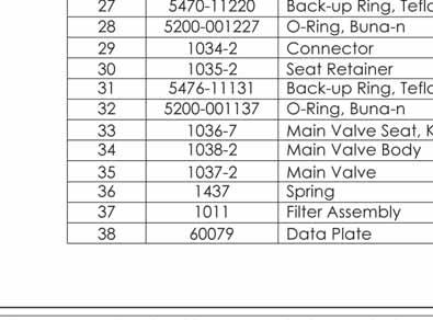


151
152 Fig 6.15 RP404 Pressure Regulator ( psi) (Drawing Number: P S1) OM P1805-OM-307 R9 Chapter 6


 OUTLET PRESSURE RANGE : 0-1500psi (0-100bar) REPAIR KIT PART No.")
 ALL DIMENSIONS BEFORE PLATING (UOS)")

153 Spares SENSOR ASSEMBLY ITEM PART No. DESCRIPTION Qty Valve Cap Back-up Ring, Teflon O-Ring, Viton Retaining Plate Retaining Ring Washer Valve Spring Valve Valve Seat, CTFE Valve Cap, S.S Orifice O-Ring, Viton Regulator Body Venturi Tube Connector Washer Vent Valve Rod Bonnet Load Spring Spring Cap Assembly Thrust Washer Thrust Bearing Thrust Washer Handknob Label Plug Screw Retaining Ring Spring Limit Screw Vent Label Plate Back-up, Sensor Sensor Seat Retainer Vent Valve Seat, CTFE Vent Valve, S.S Spring, S.S O-Ring, Viton O-Ring, Viton Data Plate WASHER NOTES DIVEX OWNS THE COPYRIGHT OF THIS DOCUMENT AND ANY DESIGN RIGHT HEREIN. IT IS SUPPLIED IN CONFIDENCE AND MUST NOT BE USED FOR ANY PURPOSE OTHER THAN THAT FOR WHICH IT IS SUPPLIED AND MUST NOT BE REPRODUCED WITHOUT PERMISSION IN WRITING FROM THE OWNERS. INLET PRESSURE RANGE : psi (0-255bar) OUTLET PRESSURE RANGE : psi (0-100bar) REPAIR KIT PART No. : (SEE TABLE) DIVEX PART No. : RK204 1 DENOTES CHANGES MADE AT THIS REVISION ALL DIMENSIONS SHOWN ARE IN MM (UOS) ALL DIMENSIONS BEFORE PLATING (UOS) REMOVE ALL SHARP EDGES AND BURRS DIMENSIONAL TOLERANCES MACHINING FABRICATION NO DECIMAL PLACES ONE DECIMAL PLACE TWO DECIMAL PLACE ANGULAR TOLERANCE ±1.0 ±0.2 ±0.05 ±0.5 SIZE >0 <100 SIZE >100 <500 SIZE >500 ANGULAR TOLERANCE ±0.5 ±1.5 ±3.0 ±0.5 MATERIAL FINISH N/A N/A THIRD ANGLE PROJECTION R06 R05 R04 R03 R02 R01 R00 REV MODEL AND PARTS LIST UPDATED JR 12/01/15 SC ISSUED FOR MANUFACTURE DESCRIPTION ECN No MRM 05/03/09 DO NOT SCALE DRAWING BY DATE JM AUTH.BY TITLE REGULATOR, PRESSURE, psi DRAWING No. PART No. SIZE A2 RP404 P S1 SCALE 1:1 SHT REV PRODUCT / PROJECT No. P OF R01 1 DIVEX LIMITED ENTERPRISE DRIVE WESTHILL ABERDEEN AB32 6TQ UNITED KINGDOM Tel : +44(0) Fax : +44(0) info@divexglobal.com
154 (Intentionally Blank) 98 OM002 Chapter 6 P1805-OM-307 R9
155 CHAPTER 7 - GAS BOOSTER CONTENTS 7.1 General Description Technical Specification Unloader Circuit Freshwater Cooling Circuit Safety Cut-Outs Main Gas Circuit Booster Starter Control Box Storage Inhibiting Chart De-inhibiting Chart Routine Maintenance & Fault Finding Periodic Checks Servicing Chart Oil Pressure Adjustment Belt Drive Tension Adjustment Lubricating Oils Fault Finding Overhaul Booster Assembly K651/454 Compressor First Stage Assembly - Cylinder Line 4 1/4 Diameter /4 Dia Cylinder - First Stage Dismantling Servicing Assembly Oil Wiper Packing Assembly Oil Wiper Packing Assembly Concentric Type Combined Suction & Delivery Valve Dimensions & Table of Wear Limits - Cylinder Line 4 1/4 Diameter Torque Loading Chart - First Stage Cylinder (4 1/4 Diameter) Second Stage Assembly - Cylinder Line 2 5/8 Diameter Description /8 Diameter Cylinder - Second Stage Dismantling Servicing Assembly Oil Wiper Packing Assembly Oil Wiper Packing Assembly Suction Valve Delivery Valve Assembly Dimensions & Table of Wear Limits - Cylinder Line 2 5/8 Diameter Torque Loading Chart - Second Stage Cylinder (2 5/8 Diameter) Gauge Panel Cooler Assembly Description Dismantling Servicing Assembly Page OM P1805-OM-307 R9 Chapter 7
156 First Stage Cooler Assembly Second Stage Cooler Assembly Crankcase Assembly Description Crankcase Assembly Dismantling Servicing Assembly Main Bearing Housing Unit Main Bearing Housing Unit Main Bearing Housing Unit Centre Bearing Housing Unit Connecting Rod Unit Oil Pump Replaceable Cartridge Oil Filter Assembly Replacement Oil Filter Cartridge Dimensions & Table of Wear Limits - Crankcase Assembly Torque Loading Chart - Crankcase Assembly Unloader Valve Assembly Operation Description Dismantling Servicing Assembly Unloader Valve Assembly Relief Valves Description Servicing Cooling Water Pump Description Dismantling Servicing Assembly Cooling Water Heat Exchanger Seawater/Freshwater Description Installation By-Pass Valve Tescom Regulator General Specifications Pressure Control Valve Single Stage Solenoid Valves Unloader Solenoid Valve High Pressure Bypass Solenoid Valve Non-return Valve General Specifications Materials Pneumatic Inlet Shut-off Valve Dismantling Assembly Double Acting Actuator Gas Pressure Switches Stage One Pressure Switch Pressure Adjustment Stage 2 Pressure Switch Pressure Adjustment High Gas Temperature Switch Description Temperature Adjustment OM002 Chapter 7 P1805-OM-307 R9
157 Maintenance Low Oil Pressure Switch Description Pressure Adjustment (Single Step Pressure Switch) Maintenance Electric Motor Fitting Pulleys Wiring Up Routine Cleaning Bearings Maintenance Fault Finding Type: Leroy Somer 37kw (50Hp) 400 V 3ph 50/60Hz Appendix A Model K651 Service Spares Kits Appendix B Gas Booster Appendix C Main Pipework Appendix D Gas Booster Starter Panel Appendix E Control Equipment Appendix F Gas Booster Starter Panel Appendix G Belt Drive OM P1805-OM-307 R9 Chapter 7
158 7.1 GENERAL DESCRIPTION The purpose of the Electric Gas Booster (Fig 7.1) is to take the exhaust gas from the Reprocessing Unit at pressures, which vary according to dive depth and compress it to the appropriate supply pressure for that depth. Details of inlet and outlet pressure etc. can be found in the table below. Fig 7.1 Electric Gas Booster It can be seen from the table that the compression ratio of the plant falls as dive depth increases, therefore below a depth of 150 msw the first stage is no longer required and must be manually bypassed. Pressure switches ensure that the booster shuts down if this is not done. Compression Ratios Dive Depth (m) Inlet Pressure Barg Interstage Pressure Barg Delivery Pressure Barg Typical Plant Throughput -- CFM Compressor Flow Actual CFM Both stages compressing Stage two only compressing Stage one recirculating * * **Based on 2 divers at a heavy work rate (75 ltr/min RMV) 102 OM002 Chapter 7 P1805-OM-307 R9
159 7.1.1 Technical Specification Description: Twin Cylinder, Two Stage, Oil Free, Watercooled Booster Compressor. Number of Cylinders 2 Bore Stage 1 4 1/4 (108.0mm) Stage 2 2 5/8 (66.7mm) Stroke Cooling 4 (101.6mm) Mains Water 10.0 gallons/minute Flow (45.5 litres/minute) Direction of Rotation Lubrication Oil Pressure Sump Capacity Speed Maximum Inspired Pressure Maximum Delivery Pressure Maximum Compression Ratio Inlet Delivery Water Inlet Water Outlet Height Width Length Weight Clockwise looking on flywheel Force Feed from integral oil pump 50lb/in 2 (3.4 Bar) 13 pints (7.4 litres) 705 RPM 250lbf/in 2 (17.3 Bar) 1450lbf/in 2 (100 Bar) 7:1 Max 30mm 22mm 3/4 BSP 3/4 BSP 61 (1549mm) (781mm) (832mm) 1140lb (517 Kg) OM P1805-OM-307 R9 Chapter 7
160 7.1.2 Unloader Circuit Fig 7.2 Unloader Circuit The unloader circuit (Fig 7.2) allows automatic dumping of any moisture which is condensed out of the gas by the inter cooler and after cooler. It also completely unloads the booster in the event of the booster being stopped. These unloaders are pneumatically operated, the first stage being held closed by a regulated supply from the booster outlet and the second stage by the first stage unloader inlet line. This circuit is controlled by a timer operated solenoid valve which closes periodically allowing the unloaders to dump any moisture accumulated. This timer also waits 10 seconds after initial starting before closing the unloaders to allow this machine to accelerate off load. In addition, when the booster is stopped and the solenoid valve closes, allowing the unloaders to dump the gas contained in both stages, a pneumatically actuated ball valve at the booster inlet closes off preventing any gas upstream from being lost. 104 OM002 Chapter 7 P1805-OM-307 R9
161 7.1.3 Freshwater Cooling Circuit Fig 7.3 Freshwater Cooling Circuit The gas is cooled after each stage by the inter cooler and after cooler respectively. These form part of the freshwater cooling circuit (Fig 7.3) which directly cools the booster itself. Heat is dissipated from this closed circuit by means of a seawater/freshwater heat exchanger. The pump for this circuit is driven directly from the motor Safety Cut-Outs Temperature switches at the outlet of each stage shut down the booster if the gas temperature exceeds 200 o C. High pressure cut outs and relief valves on each stage ensure pressure never exceeds 46 bar (inter stage) and 105 bar (final stage). There is also a pressure switch to stop the machine if the lubricating oil pressure falls below 1.72 bar. OM P1805-OM-307 R9 Chapter 7
162 7.1.5 Main Gas Circuit Fig 7.4 Main Gas Circuit On initial start up the booster automatically charges itself with gas from the Volume Tank by opening a solenoid valve, which bypasses gas back past the outlet check valve. A dome-loaded regulator is connected between the machine outlet and inlet. Its outlet is set 1 bar below the BPR Loader pressure, hence the booster will circulate gas around this loop keeping itself in equilibrium and maintaining the system, after the Reprocessing Unit BPR, at a pressure 1 bar below the setting on the BPR loader in dive control. When a diver goes onto recovery the recovered gas flows from the Reprocessing Unit to the booster inlet. Due to this additional gas, the flow from the bypass regulator is reduced as the booster compresses this additional gas and delivers it to the Volume Tank. Hence it can be seen that the plant can automatically compensate for any variation in the inlet flow rate due to a diver s work rate keeping itself in equilibrium Booster Starter Control Box 1. Motor Control - The motor control circuit has a local and remote selector switch, with local and remote emergency stop-lock and start switches and mains indicator lights. The motor is wired in a star-delta configuration, starting in a star connection and changing to delta connection after approximately 8 seconds. Upon starting the booster the running light illuminates and hours of running are recorded on an hour meter. 2. Moisture Dump/Unloaders - Upon starting the booster, a timer T1 sets the period that the booster runs unloaded and dumping moisture. T1 is pre-set, usually to 10 seconds (maximum 30 seconds). A second timer T2 sets the period between unloading during running. T1 additionally controls the initial period that the booster runs unloaded and dumping moisture. 106 OM002 Chapter 7 P1805-OM-307 R9
163 7.2 STORAGE The booster is normally supplied uninhibited. If there is likely to be a long delay between installation and commissioning (in excess of six months) it can be inhibited prior to delivery. Consideration must also be given to this if the system is to be unused for a significant period (see Inhibiting Chart section 7.2.1). Inhibiting Oils (Always follow the oil suppliers instructions) Make Inhibiting Oil Shell Ensis Oil 30 BP Protective Engine Oil 30 Esso Rustban 396 Di-inhibiting Procedures see De-inhibiting Chart (page 108) Inhibiting Chart Period (months) Anticipated Conditions Procedure 1-6 Normally Dry Seal off all openings to booster with suitable tape. 6+ Normally Dry 1. Drain oil sump and refill with inhibiting oil. 2. Run machine or hand turn until all bearing surfaces are wet. 3. Seal off all openings with suitable tape. Any Period Damp or risk of condensation 1. Follow above procedures. 2. Envelope machine in heavy gauge polythene sheet sealed with a suitable tape. 3. Enclose a small quantity of desiccant material i.e. silica gel or alumina, within the plastic sheeting. OM P1805-OM-307 R9 Chapter 7
164 7.2.2 De-inhibiting Chart Period (months) Procedure Remove all sealing tape. 2. Follow initial starting procedure (see Commissioning) Run till warm. 2. Drain inhibiting oil from sump. 3. Refill with the correct lubricating oil. 7.3 ROUTINE MAINTENANCE & FAULT FINDING Periodic Checks At the intervals stated the servicing below should be carried out to ensure the long life of the booster Servicing Chart Period Daily Operation 1. Check oil level. Refill if necessary with the recommended lubricant (section page 109). 2. Check level in header tank. Top up with 50/50 water/glycol if necessary. Every 1000 Hours Remove and service suction and delivery valves. Every 2000 Hours Check drive belt tension and adjust if necessary (section page 109). Every 5000 Hours or annually (Whichever is sooner) 1. Drain sump and refill with the recommended lubricant (section page 109). 2. Clean or replace oil filter. 3. Carry out general overhaul (section page 114) Oil Pressure Adjustment 1. Run compressor until the oil is warm and check oil pressure - it should be 50 psi (3.4 bar). 2. To adjust pressure release the locknut and turn the adjusting screw clockwise to increase pressure and anti clockwise to decrease pressure. Re-tighten locknut when adjustment is complete. 108 OM002 Chapter 7 P1805-OM-307 R9
165 7.3.4 Belt Drive Tension Adjustment 1. Firmly press down on the belts with the hand halfway between the pulley centres. If the adjustment is correct it should deflect approximately 1 1/2 (38mm). 2. If not correct loosen the motor holding down bolts and reposition the motor. 3. Ensure correct alignment of the pulleys. Re-tighten the bolts and re-check the tension (Fig page 200) Lubricating Oils The appropriate lubricating oils are listed below. Shell Talpa 30 Shell Turbo 78 Petrofina Solco AC68 Texaco Cepheus Esso Teresso L100 Anderol 555 Other mineral oils approved by W & J may be used. All new Boosters leaving Divex will contain Anderol 555. OM P1805-OM-307 R9 Chapter 7
166 7.3.6 Fault Finding Fault Probable Cause Solution No oil pressure on initial start up (commissioning and after overhaul). 1. Wrong rotation. Check rotation. 2. Oil pump not primed. Concentric pump, remove pump. Fill with oil and replace. 3. Faulty pressure gauge. Replace pressure gauge. Low oil pressure. 1. Blocked oil suction filter. Remove filter, clean and degrease. 2. Air leakage into suction side of oil of pump i.e. suction filter cover, plug in base of housing or face gasket of main bearing housing. 3. Faulty oil pressure relief valve. 4. Incorrect oil pressure relief valve setting. 5. Worn or damaged compressor bearings. Check for tightness of pipe fittings. Renew gasket. Dismantle and examine spring, ball and seat. Renew components as necessary. Reset relief valve. Fit new bearings. 6. Faulty or worn oil pump. Fit new pump. 7. Sump needs refilling. Replenish as necessary. 8. Faulty pressure gauge. Replace pressure gauge. 9. Damaged internal oil suction pipe or slack union. 10. Excessive wear in oil transfer bush or connecting rod big ends necessary. (1200 Series only). Remove crankcase side cover and check for damage and tightness. Check clearances and renew components as necessary. 110 OM002 Chapter 7 P1805-OM-307 R9
167 Fault Probable Cause Solution Inability to maintain normal output. 1. Blocked inlet filter. Service in accordance with details given on instruction plate attached to the suction filter/silencer unit. 2. Belt slip (on belt driven compressors). 3. Pressure control setting incorrect. 4. Faulty suction or delivery valves. Re-adjust belt. Reset pressure control. Remove and dismantle the valve assemblies. Examine the components for damage and wear and renew as necessary. 5. Excessive air consumption. Check system for leaks and whether the air requirements of the system supplied have increased. 6. Worn piston rings. Renew rings. 7. Faulty unloader, relief valves or drain valves. Check for leakage and rectify. 8. Blocked delivery filter. Clean or renew. Excessive air/gas blowing from crankcase. Compressor knocking (when unloaded). 9. Worn pressure packings (Oil free comps only). 1. Piston rings worn or sticking in grooves. 2. After a considerable period of use, a fall in compressor performance may be due to general wear of pistons and cylinder bores. Excessive play in big ends or gudgeon pins. Renew pressure packings. Fit new rings. NOTE: New rings must be fitted into correct respective grooves. When the word TOP appears the ring must be fitted with this face upwards. Fitting new piston rings only will not effect a long term improvement - pistons and cylinders should be renewed as necessary. Stop compressor, dismantle and check all moving parts. Thoroughly clean all parts and oil-ways. Renew bearings etc. as necessary. OM P1805-OM-307 R9 Chapter 7
168 Fault Probable Cause Solution Low first stage pressure. 1. Valves not seating correctly in first stage cylinder. 2. Air/gas leak in piping between first stage delivery and succeeding stage suction. 3. Intercooler drain valve open or leaking. Reseat or replace valves. Locate leak and repair. Shut drain valve or rectify leak. 4. Relief valve not seating. Check for leakage and rectify. 5. Faulty pressure gauge. Replace pressure gauge. 6. Clogged suction air filter. Clean filter. 7. Air/gas leak through pressure packing (Oil free compressors only). 8. First stage unloader not seating correctly. Renew pressure packings. Check unloader valve and seat for damage. Renew as necessary. Low second stage pressure. If preceding stage is satisfactory. 1. Air/gas leak in piping between second stage delivery and succeeding stage suction. Locate leak and repair. 2. Second stage valves seating correctly. 3. Second stage relief valve not seating. 4. Second stage unloader not seating correctly. Reseat or replace valves. Check for leakage and rectify. Check unloader valve and seat for damage. Renew as necessary. 5. Faulty pressure gauge. Replace pressure gauge. Low third stage pressure. If preceding stage is satisfactory. 1. Air/gas leak in pipes from third stage delivery to succeeding stage suction. Locate leak and repair. 2. Third stage valves not seating correctly. 3. Third stage relief valve not seating. 4. Third stage unloader not seating correctly. Reseat or replace valves. Check for leakage and rectify. Check unloader valve and seat for damage. Renew as necessary. 5. Faulty pressure gauge. Replace pressure gauge. 112 OM002 Chapter 7 P1805-OM-307 R9
169 Fault Probable Cause Solution Low final stage pressure. 1. Air/gas leak in piping after final stage delivery. 2. Excessive air/gas consumption. 3. Final stage valves not seating correctly. 4. Final stage relief valve not seating correctly. 5. Final stage unloader not seating correctly. Locate leak and rectify. Check system for leakage or above normal demand. Reseat or replace valves. Check for leakage and rectify. Check unloader valve and seat for damage. Renew as necessary. 6. Faulty pressure gauge. Replace pressure gauge. High final stage pressure. Compressor starts but will not load. 1. Final check valve restricted or jammed. 2. Press maintaining valve restricted or jammed. 3. Final delivery pipe from compressor to air receiver blocked. 1. Low oil pressure (insufficient to operate unloaders). 2. Unloader valve stuck open or seat damaged. Stop compressor immediately. Repair or replace check valve. Stop compressor immediately. Repair or replace pressure maintaining valve. Stop compressor immediately. Remove, thoroughly clean or renew pipe. See fault finding table for low oil pressure. Check unloader spindle for freedom of movement and damage to seat or valve. Renew parts as necessary. 3. Defective solenoid valve. Repair or replace defective unit. First stage unloader valve blows off while compressor is running. 1. Valve leaking. Replace worn valve parts. 2. Insufficient oil pressure to close valve. Check oil pressure and adjust. See fault finding table for low oil pressure. Second, third or fourth stage unloader valve blows off while compressor is running. Second, third or fourth stage unloader valve does not shut down when compressor is running or fails to open when compressor is shut down. Valve leaking. Piston sticking in valve housing. Replace worn valve parts. Remove unloader valve piston and polish as necessary. Before assembly lubricate with brake cylinder lubricant. OM P1805-OM-307 R9 Chapter 7
170 7.4 OVERHAUL Booster Assembly The Model K651/454 is a two stage, oil free, twin cylinder, watercooled, booster compressor used to boost air or gas already under pressure up to a maximum pressure of 1450 lb/in 2 (100 Bar). The machine is designed for continuous operation. Drive is from an electric motor through vee belts to the compressor flywheel. The motor and compressor are mounted on a common fabricated steel baseplate. The compressor is arranged with the cylinders mounted vertically. The first stage has a 4 1/4 inch (108mm) diameter bore and the second stage has a 2 5/8 inch (68.8mm) diameter bore. Both cylinders have a common stroke of 4 inches (101.6mm). The aluminium alloy pistons are bolted to the piston rod/crosshead assemblies and each contain one T.F.E. filled bearing ring and seven T.F.E. filled compression rings which require no lubrication. The cast iron compression cylinders are fitted with fine honed stainless steel liners. Inlet pressure is fed to the underside of each piston to reduce connecting rod and bearing loadings. Mounted beneath each compression cylinder is a stainless steel, water cooled, pressure packing assembly. Twenty P.T.F.E. packing rings, loaded by garter springs, act on the hardened piston rods to produce a gas tight seal. Each piston rod also passes through an oil seal stuffing box mounted between the guide cylinder and the pressure packing assembly.this ensures that oil providing lubrication to the guide cylinders does not enter the compression cylinders. The seal assembly comprises a cast iron stuffing box containing a multi-element oil wiper pack. Wiped oil is returned to the crankcase by means of oil drainways. The piston rods are of sufficient length to ensure that the area wiped by the oil seal does not enter the pressure packing. Each piston rod/crosshead assembly is attached to a forged steel connecting rod by a steel gudgeon pin retained by circlips. The small end bearings are of the needle roller bearing type and the connecting rod big end bearing are of the steel backed white metal type. The double throw crankshaft is supported within the crankcase by two steel backed white metal bearings inserted into housings by each end of the crankcase. Lubrication of the bearings is by pressure feed and splash from an oil pump drawing from the sump and discharging via a full flow canister type filter. The guide cylinder bores are lubricated by splash. The intercooler and aftercooler are mounted in two cooler casings mounted vertically adjacent to the cylinders. Provision is made for the separation and collection of moisture after cooling. Each stage of the compressor is fitted with an automatic unloader valve which allows the compressor to start in an unloaded condition and also allows moisture condensate collected during operation to be drained when the compressor stops. 114 OM002 Chapter 7 P1805-OM-307 R9
171 Fig 7.5 K651 / 454 Compressor OM P1805-OM-307 R9 Chapter 7
172 Fig / 454 Compressor K651/454 Compressor Part No. Divex Order Code Description Qty Ref. A Crankcase Assembly /01 - Pulley DX2157 Key 1 3 GR Cylinder Line Stage GR Cylinder Line Stage A65151 GE151 Cooler Unit Stage A65152 GE152 Cooler Unit Stage OM002 Chapter 7 P1805-OM-307 R9
173 Part No. Divex Order Code Description Qty Ref. W42886/1 - Cooler Support Assy 1 8 Y37294/4 GE155 Plug HP 3/4 BSP /4 GC151 Seal 3/ BL9/29 GC545 Bolt 1/2 UNC x 7/8 Long /11 DX9931 Spring Washer BL9/11 - Bolt 3/8 UNC x 3/4 Long /3 - Washer /1 - Cooler Support Bracket 2 16 BL9/11 - Bolt 3/8 UNC x 3/4 Long 2 17 Y27820 GE135 Coupler 1 1/4-1 1/4 BSP 1 18 Y37291/5 GC306 Coupler 1-3/4 BSP /8A GE123 Probe Block /9 GC359 Probe Block GE29933 Temperature Switch 2 22 W42923 DX5620 Moisture Separator Tube Assy GE128 Moisture Separator Head GE129 Moisture Separator /57/90 GE038 O-ring Seal /3 GE137 Hex Nipple 1/4 BSP /2 GC426 Equal Tee 1/4 BSP /3 GC131 Water Relief Valve /5 GC134 Relief Valve Stage G12586/2 GC10526 Unloader Valve /6 DX1543 Nut 5/16 BSF 4 32 SL8/51 - Stud 5/16 BSF X 6 1/2 Long /15 - Washer 5/ /4 GC20440 Plug 1/2 BSP GC026 Crankcase Breather 1 36 A Gauge Panel Gauge Panel Bracket Gauge Panel Bracket 2 39 BL8/34 - Bolt 1/4 UNF x 1/2 Long 6 40 OM P1805-OM-307 R9 Chapter 7
174 Part No. Divex Order Code Description Qty Ref. 4919/53 GC357 Nut GC20441 Angle Block 1/4 BSP - 1/4 NPT /3 GC20443 Elbow 1/4 BSP - 8mm /5 GE084 Water Manifold /6 DX4111 Water Manifold /18/90 GE041 O-ring /15P DX3094 Stud Elbow 30mm - 1 1/4 BSP / LEOTITE DX9182 Gasket /7P GE138 Stud Elbow 6mm - /4 BSP /24P GE139 Stud Coupling 30mm - 1 1/4 BSP /7P DX3092 Stud Coupling 22mm - 3/4 BSP /9 GE127 Coupler 3/4-3/4 BSP /22P DX3099 Stud Coupling 6mm - 1/4 BSP /6 GE082 Relief Valve Stage /5P GE130 Stud Tee 1/4 BSP x 6mm /1P GC20442 Stud Barrel Tee 1/4 x mm /3P DX3095 Equal Elbow 30mm /5P DX1152 Stud Elbow 22mm x 3/ /1P DX996 Swivel Elbow 22mm x 3/ /1P DX2315 Swivel Tee 22mm x 3/ GE030 Gasket /1 GE143 Valve Body /2 GE144 Needle Valve Screw /42 GC004 Seal Washer 3/4 BSP /11 DX2311 Pipe 30mm O/Dia 2 FT /6 GC331 Pipe 22mm O/Dia 8 FT /5 GC20439 Plug 3/4 BSP /3 GC318 Pipe 6mm O/Dia 16 FT /1 DX2310 Straight Coupler 22mm BSP OM002 Chapter 7 P1805-OM-307 R9
175 Part No. Divex Order Code Description Qty Ref /7 GE140 Straight Coupler 15mm - 1/4 BSP /1 GE141 Reducing Tee 22mm - 15mm - 3/4 BSP /1 GE142 Red. Bush Tee 22mm - 15mm 3/4 BSP /4 DX2309 Pipe 22mm O/Dia 6 FT /5 - Pipe 15mm O/Dia 9 FT /7 GC20446 Plug 1 79 Y37293/3 - Reducing Bush 1/2-1/ /2 DX3090 Seal /4V GC151 Seal - 3/4 BSP /7V DX10195 Seal - 1 1/4 BSP /1 DX247 Seal 1/2 BSP /9 DX3922 Seal - 1/4 BSP GE131 Tee Block /2 GC427 Socket /4 GC311 Nipple /3 - Adaptor 3/8 x 1/4 BSP /2 DX1158 Elbow - 2mm x 3/4 BSP 3 95 Y37293/4 GC307 Adaptor 3/8 BSP X 1/2 BSP /14 DX3098 Adaptor 1/2 BSP X 1/2 BSP /3 GC166 Seal - 3/8 BSP /B - Pipe - St.2 Delivery to St.2 Cooler /E - Pipe - St.1 Cooler to St.2 Suction /C - Pipe - St.2 Cooler to Comp Manifold /F - Pipe - Cooler Link /1 GE122 Low Oil Pressure Switch /6P DX1148 Stud Tee 1/8 BSP - 6mm OM P1805-OM-307 R9 Chapter 7
176 7.4.2 First Stage Assembly - Cylinder Line 4 1/4 Diameter The cylinder head is manufactured in cast iron and is suitably ported to incorporate the combined suction and delivery valve and the cooling water exhaust connection. A stainless steel concentric type suction and delivery valve is retained by a cast iron valve cover, sealed by o-rings and incorporating the suction and delivery connection. The piston is manufactured in aluminium alloy and is fitted with one TFE filled guide ring and seven TFE filled compression rings. The piston is bolted to the crosshead/piston rod assembly. A floating gudgeon pin, retained by circlips connects the crosshead assembly to the connecting rod. The underside of the piston is pressure balanced by a connection to the suction pressure to reduce bearing loadings. The compression cylinder is manufactured in cast iron and is fitted with a stainless steel liner. To prevent leakage from the compression cylinder, the hardened piston rod passes through a set of water cooled pressure packings and a set of oil wiper packings. A distance piece located between the packings ensures that the area of piston rod wiped by the oil wiper packings does not enter the pressure packings. The pressure packing comprises multiple segmented PTFE packings rings, loaded by garter springs, which act on the hardened piston rod to provide an effective seal. The assembly is water cooled to dissipate friction and compression heat build up. The oil wiper packing is mounted above the guide cylinder and comprises a cast iron stuffing box assembly housing a set of four segmented white metal wiper rings, loaded by garter springs, which act on the piston rod to prevent oil leakage into the compression cylinder. Wiped oil drains back into the crankcase. The guide cylinder is manufactured in cast iron with the crosshead running in a fine honed bore. 120 OM002 Chapter 7 P1805-OM-307 R9
177 Fig 7.7 First Stage Cylinder 4 1/4 Diameter Gasmizer Booster Section View Cylinder Head - 1 of 2 OM P1805-OM-307 R9 Chapter 7
178
179 Fig /4 Dia Cylinder 122 OM002 Chapter 7 P1805-OM-307 R9
180 /4 Dia Cylinder - First Stage Part No. Divex Order Code Description Qty Ref. A Cylinder Head Assembly Comprising ref. nos. 1A-1G GE094 Cylinder Head 1 1A DX1478 Valve Cover 1 1B 9655/3 GE034 o-ring Seal 1 1C 9017/73/75S GE035 o-ring Seal 1 1D SL12/4 DX2154 Stud - 5/16 UNC x 3/4 E/L 2 1E 4919/64 DX1543 Nut - 5/16 UNC 2 1F 2547/3 - Washer 2 1G U GC292 Piston Unit Comprising ref. nos. 2A-2K 1 W42847 DX187 Piston Rod/Crosshead 1 2A GE092 Piston 1 2B GE103 Shim 1 2C *42857/A GE104 Shim As reqd 2D DX594 Bolt 1/2 UNC x 2 3/4 E/L 1 2E DX189 Tab Lock Washer 1 2F GE003 Piston Ring 7 2G GE004 Guide Ring 1 2H GC222 Gudgeon Pin 1 2J 9107/7 GE007 Circlip 2 2K U GE096 Cylinder Unit Comprising ref. nos. 3A-3F 1 W42843 DX192 Cylinder/Liner 1 3A 9655/3 GE034 o-ring Seal 1 3B 9771/82 DX2215 Cap Screw 3/8 UNC x 5 Long 8 3C D SL12/37 DX1707 Stud 1/2 UNC x 2 3/4 E/L 6 3E 4919/59 GE21033 Nut 1/2 UNC 10 3F SL12/46 - Stud 1/2 UNC x 2 1/4 Long 4 3G 2547/11-1/2 Spring Washer 5 3H BL9/54 - Bolt 1/2 UNC x 3/4 Long 1 3I U GE093 Water Jacket Unit Comprising ref. nos. 4A-4D 1 OM P1805-OM-307 R9 Chapter 7
181 Part No. Divex Order Code Description Qty Ref Water Jacket 1 4A SL12/4 DX2154 Stud 5/16 UNC x 3/4 E/L 2 4B 2547/8 GC336 Washer 2 4C 4919/64 DX1543 Nut 5/16 UNC 2 4D U Wiper Packing Chamber Unit Comprising ref. nos. 5A-5E Wiper Packing Chamber 1 5A 8632 GC026 Breather 1 5B C SL12/28 GC20452 Stud 1/2 UNC x 2 3/8 E/L 4 5D 4919/59 GE21033 Nut 1/2 UNC 4 5E U Guide Cylinder Unit, Comprising ref. nos. 6A-6C DX287 Crosshead Guide 1 6A SL12/39 DX4817 Stud 1/2 x UNC x 4 1/8 E/L 4 6B 4919/59 GE21033 Nut 1/2 UNC 4 6C BU GE089 Pressure Packing Unit 1 7 BU GE010 Wiper Packing Unit 1 8 BU GE011 Suction and Delivery Valve Distance Plate - Cylinder GE134 Pressure Packing Chamber Wiper Packing Housing GC351 Distance Plate - Packings GE027 Gasket - Head 1 15 MR N GE032 O-ring Seal Cylinder Base /LEOTITE GE022 Gasket 2 17 *Thickness of shim Ref No.2D to be sized to give /0.040 clearance under head when cold. 124 OM002 Chapter 7 P1805-OM-307 R9
182 Dismantling 1. Drain cooling water and ensure all pressure is vented from system. Ensure compressor motor is electrically isolated. 2. Remove suction and delivery pipework and water manifold. 3. Remove four nuts securing the valve cover. 4. Remove valve cover and life out valves using extraction tool TS Remove eight socket head cap screws securing head to the cylinder. Lift off head and recover o-ring. 6. Dismantle valve assembly by unscrewing the nut and socket cap screws and separating valve components. NOTE Do not hold the valve in a vice when dismantling or assembling as this will result in distortion. To hold the valve during servicing, vertically secure two pegs in a vice and locate the valve seat slots onto the pegs. 7. Remove water manifold and lift off water jacket. 8. Remove six cylinder flange nuts and life off cylinder. 9. Remove bolt in piston crown and withdraw the piston. NOTE If required, the piston may be removed without dismantling the cylinder. Remove bolt in piston crown, insert two 1/4 UNC extraction bolts into piston crown and withdraw the piston. 10. Withdraw cylinder spacer and recover o-rings. 11. Remove pressure packing cooling water connections. Remove nuts and withdraw pressure packing chamber. 12. Remove pressure packing case nuts and separate pressure packing. Withdraw packing rings and containers over piston rod. Ensure each packing ring is not mixed with another. Note the sequence of assembly and position of each ring during dismantling. 13. Remove wiper packing chamber. 14. Remove six socket head cap screws from wiper pack cover. Withdraw cover. 15. Rotate compressor by hand until the piston rod has carried packings clear of the stuffing box. NOTE Particular care should be taken in dismantling the packing assembly. Care must be taken in handling not to damage the edges of the wiper rings or roll them over in any way. Wiper rings must be held square with the piston rod. 16. Separate packing rings enable each segmented ring to be gripped in turn and by gentle pulling against the garter spring, the ring can be removed without touching the piston rod and damaging the wiping edges. 17. Remove packing housing and recover gasket. Remove spacer and recover gasket. OM P1805-OM-307 R9 Chapter 7
183 18. Remove four nuts, lift off the guide cylinder and recover gasket. NOTE Support the connecting rod and crosshead/piston rod assembly to avoid damage as the guide cylinder is lifted clear. 19. Remove circlips and with a centrally applied pressure, drive out gudgeon pin. Remove crosshead from the connecting rod. NOTE Support crosshead against side thrust if a drift is used. Do not separate crosshead and piston rod. These components are manufactured as a complete unit. Servicing is by unit replacement only Servicing 1. Clean and examine crosshead/piston rod assembly for signs of wear or damage and replace if wear exceeds limits given in Table of Wear Limits. Examine gudgeon pin for signs of scoring, cracking or wear and replace as necessary. 2. Inspect wiper packing rings for smooth bedding surfaces and sharp wiping edges. Renew when rings have worn until ends of segments butt. Do not remove material from ends of segments. Do not mix segments of one ring with another. Ensure smooth faces on stuffing box containers. Lap as required. Servicing is by unit replacement only. 3. Inspect pressure packing rings for signs of damage or wear. Renew when rings have worn until ends of segments butt. Do not remove material from end of segments. Do not mix segments of one ring with another. Ensure smooth faces on stuffing box containers. Lap as required. Servicing is by unit replacement only. NOTE If new pressure packing rings are to be fitted, it will be necessary to roughen the mating surfaces of the piston rod to enable the new rings to bed in. This is best achieved by using a fine grade of emery cloth to give a 45 o crosshatch finish of approximately mirco inch CLA. After roughening the surface, ensure that all traces of abrasive material are removed from the piston rod by washing with a suitable solvent. Failure to roughen the piston rod could lead to premature wear of the new rings due to a very high piston rod temperatures. Do not roughen the surface of the piston rod which passes through the oil wiper packing assembly. 4. Examine pressure packing o-ring seals for signs of damage or deterioration and replace as necessary. Clean o-ring grooves and cooling chambers, removing any sediment or scale. 5. Examine piston and rings for signs of wear or damage and replace if worn below limits given in Table of Wear Limits (page 132). 6. Examine fit of piston rings and bearing ring in piston. Renew if worn below limits given in Table of Wear Limits (page 132). NOTE If new piston compression and bearing rings are to be fitted, it will be necessary to roughen the mating surfaces of the compression cylinder to enable the new rings to bed in. This is best achieved by using the appropriate size Flexi-Hone or by a fine grade of emery cloth to give a 45 o crosshatch finish of approximately micro inch CLA. Ensure that all traces of abrasive material are removed from the cylinder wall by washing with a suitable solvent. Failure to roughen the cylinder wall could lead to premature wear of the new rings due to very high cylinder bore temperatures. 126 OM002 Chapter 7 P1805-OM-307 R9
184 7. Examine compression cylinder for signs of wear or scoring and replace as necessary. 8. Examine cylinder head and attachment for signs of obvious damage. 9. Inspect o-ring seal in cylinder head for signs of wear or damage and replace as necessary. 10. Examine o-ring seal in the valve cover for deterioration or damage and renew if necessary. 11. Soak all component parts of the valve assemblies in white spirit or Chlorothene VG to remove all deposits. Use a soft brush to free valve ports from all foreign matter. NOTE Never use wire brushes or tools with sharp edges to clean the seats and plates. Use cleaning agents in accordance with manufacturers instructions. 12. Examine valve component parts for signs of wear or damage. Replace valves if any springs have become weak or if any component parts are worn or cracked. After 5000 hours use, valves should be discarded. Servicing of valves is by unit replacement only. If a valve plate is not bedding all over its working face, lightly lap on a lapping plate with a fine grinding past or metal polish. Repeat the procedure on the valve seat and finish by lapping the valve seat and plate together. Thoroughly clean Assembly NOTE Renew gaskets and o-rings as necessary during assembly. 1. Replace one circlip in the crosshead and smear gudgeon pin and crosshead with lubricating oil. Insert gudgeon pin into the crosshead and connecting rod small end and drive pin home with a soft faced mallet. Replace other circlip. NOTE The crosshead should be suitably cushioned during this operation to avoid bending the connecting rod or damaging bottom end bearings. 2. Lightly lubricate crosshead and guide cylinder walls. Fit guide cylinder, using a new paper gasket as base. Replace four nuts and torque to value given in loading chart. If studs have been removed for any reason, these should be replaced with torque value as given in loading chart. 3. Refit spacer, using a new gasket at base. 4. Refit packing housing, using a new gasket at base. 5. Turn crankshaft by hand until crosshead/piston is at top of stroke. Lightly lubricate piston rod working surface. 6. Place each packing ring in turn over the piston rod, preferably using two pairs of hands to expand garter spring so that all the segments are away from rod during positioning. The assistance of another operator is desirable in this operation. If another operator is not available, use tool No.TS841 to enable rings to be placed onto rod. NOTE Take care when handling not to damage the edges of the wipers or roll them in contact with the rod. Wipers must always be held square with the guide rod. Fit rings in the order shown in the illustration of the packing assembly. The lower wiper rings nearest to the cylinder have their slotted faces downwards and plain faces uppermost. OM P1805-OM-307 R9 Chapter 7
185 7. Turn crankshaft by hand to lower ring pack into housing and when piston rod is at bottom of stroke, replace the cap and retaining screws. Torque screws to value given in loading chart. Wipe dry the guide rod and top of seal pack. 8. Refit wiper packing chamber and tighten nuts to value given in torque loading chart. 9. Turn crankshaft by hand until piston rod is at top of stroke. Ensure piston rod is clean and dry. Ensure that hands are clean to prevent oil contamination of pressure packings. 10. Assemble pressure packing. Ensure correct sequence of assembly with reference to the illustration. Ensure correct alignment of coolant, lubrication and vent chambers. NOTE Connections are stamped CI - Cooling Inlet, CO - Cooling Outlet and V - Vent. 11. When pressure packing is assembled, tighten pressure packing nuts to value given in Torque Loading Chart. 12. Rotate compressor by hand until complete assembly is drawn down onto wiper packing chamber. Fit pressure packing chamber over assembly and tighten nuts value given in Torque Loading Chart. 13. Fit cylinder spacer, ensuring correct location of o-rings. 14. Assemble piston and piston rings. Ensure gaps in adjoining rings are 180 o apart. NOTE Bearing ring is located in groove nearest piston crown. 15. Fit piston onto piston rod. Ensure correct location of shims. If a new piston is being fitted, check for correct clearance with cylinder head and adjust as necessary using new shims. NOTE Piston crown/cylinder head clearance /0.040 when cold. 16. Tighten piston socket head screw to value given in Torque Loading Chart and bend over locking tab. 17. Fit compression cylinder over piston. Carefully feed each piston ring into the bore via the chamfer at its base. Tighten nuts to value given in Torque Loading Chart. 18. Fit water jacket. Ensure correct location of o-rings. 19. Fit cylinder head. Ensure correct location of o-rings and head gasket. Tighten socket head cap screws evenly to value given in Torque Loading Chart. 20. Assemble combined suction and delivery valve with reference to the illustration. Ensure all components are positioned correctly. Tighten nuts to the value given in the Torque Loading Chart. Tighten socket cap screws. 21. Fit valve into cylinder head pockets. Lap in valve as necessary. Fit valve cover and tighten nuts to value given in Torque Loading Chart. Ensure correct location of o-ring. 22. Fit suction and delivery pipework. Connect cooling water manifolds. Fill compressor with cooling water. 128 OM002 Chapter 7 P1805-OM-307 R9
186 Fig 7.9 Pressure Packing Assembly (Drawing Number: BU ) OM P1805-OM-307 R9 Chapter 7
187
188 Oil Wiper Packing Assembly Part Number: BU (Divex Order Code: GC301) Fig 7.10 Oil Wiper Packing Assembly Oil Wiper Packing Assembly Part Number: BU Part No. Description Qty Ref BU /1 Plate 1 1 BU /2 Container 1 2 BU /3 Container 1 3 BU /4* Ring W1 2 4 BU /5* Ring W2 2 5 BU /6* Garter Spring 4 6 BU /7 Caphead Screw - 2BA x 1/2 6 7 *These items are contained within Wiper Packing Kit BU /4-6 (Divex Order Code: GE010). 130 OM002 Chapter 7 P1805-OM-307 R9
189 Concentric Type Combined Suction & Delivery Valve Part Number: BU (Divex Order Code: GE011) Part No. Description Qty Ref. BU /1 Concentric Seat 1 1 BU /2 Centre Screw 1 2 BU /3 Buffer Plate 1 3 BU /4 Valve Plate 1 4 BU /5 Spring Plate Assy, Comprising 5A 1 5 BU /15A Spring Plate 2 5A BU /6 Lift Washer Middle 1 6 BU /7 Lift Washer Middle 1 7 BU /8 MHT Nut 1 8 BU /9 Buffer Plate 1 9 BU /10 Valve Ring 1 10 BU /11 Lift Washer 2 11 BU /12 Socket Cap Screw 2 12 NOTE Ref. No. 12 Socket Cap Screws to be secured with Locite. Fig 7.11 Combined Suction and Delivery Valve OM P1805-OM-307 R9 Chapter 7
190 Dimensions & Table of Wear Limits - Cylinder Line 4 1/4 Diameter Item Design Size Inches (mm) Wear Limit Inches (mm) *Maximum Total Clearance (mm) Cylinder Bore Diameter 4.250/4.251 (107.95/107.98) Piston Diameter 4.157/ (105.58/ Guide Ring Radial Thickness (6.35) 0.22 (5.59) Guide Ring Axial Thickness Guide Ring Groove Width (9.195) (0.38) 0.375/ (9.525/9.56) Guide Ring End Gap Piston Ring Radial Thickness (2.69) (9.53) (3.07) (4.75) Piston Ring Axial Thickness Piston Ring Groove Width (7.70) (0.305) /0.312 (7.96/7.93) Piston Ring End Gap x 2 (0.71 x 2) x 2 (1.09 x 2) Pressure Packing Rings Wiper Packing Rings Replace when segment ends butt. Replace when segment ends butt. Gudgeon Pin Diameter Small End Bearing Diameter / (25.41/25.40) 1 in Nom Bore (25.39) Crosshead Diameter /3.997 (101.53/101.52) Crosshead Guide Bore 4.000/4.001 (101.6/101/62) (101.47) (.152) (101/67) NOTE Check clearances cold. 132 OM002 Chapter 7 P1805-OM-307 R9
191 Torque Loading Chart - First Stage Cylinder (4 1/4 Diameter) Item Loading LB/FT (KG/M) Cylinder Head Socket Head Cap Screw 20 (2.76) Valve Cover Studs 12 (1.66) Valve Cover Nuts 20 (2.76) Valve Nuts ( ) Pressure Packing Nuts 24 (3.32) Wiper Packing Caphead Screws 4 (0.55) Crosshead Guide/Crankcase Nuts 30 (4.15) Wiper Packing Chamber/Crosshead Guide Studs 35 (4.84) Wiper Packing Chamber/Crosshead Guide Nuts 30 (4.15) Pressure Packing Chamber/Wiper Packing Chamber Studs 35 (4.84) Pressure Packing Chamber/Wiper Packing Chamber Nuts 30 (4.15) Cylinder/Pressure Packing Chamber Studs 35 (4.84) Cylinder/Pressure Packing Chamber Nuts 30 (4.15) Piston Socket Head Screw 30 (4.15) Water Manifold Studs 13 (1.80) Water Manifold Nuts 10 (1.38) OM P1805-OM-307 R9 Chapter 7
192 7.4.3 Second Stage Assembly - Cylinder Line 2 5/8 Diameter Description The cylinder head is manufactured in cast iron and is suitable ported to incorporate the suction and delivery valves and the cooling water exhaust connection. Stainless steel ring type suction and delivery valves are retained by cast iron valve covers, sealed by o-rings and incorporating the suction and delivery connections. The piston is manufactured in aluminium alloy and is fitted with one TFE filled guide ring and seven TFE filled compression rings. The piston is bolted to the crosshead/piston rod assembly. A floating gudgeon pin, retained by circlips connects the crosshead assembly to the connecting rod. The underside of the piston is pressure balanced by a connection to the suction pressure to reduce bearing loadings. The compression cylinder is manufactured in cast iron and is fitted with a stainless steel liner. To prevent leakage from the compression cylinder, the hardened piston rod passes through a set of watercooled pressure packings and a set of oil wiper packings. A distance piece located between the packings ensures that the area of piston rod wiped by the oil wiper packings does not enter the pressure packings. The pressure packing comprises multiple segmented PTFE packings rings, loaded by garter springs, which act on the hardened piston rod to provide an effective seal. The assembly is water cooled to dissipate friction and compression head build up. The oil wiper packing is mounted above the guide cylinder and comprises a cast iron stuffing box assembly housing a set of four segmented white metal wiper rings, loaded by garter springs, which act on the piston rod to prevent oil leakage into the compression cylinder. Wiped oil drains back into the crankcase. The guide cylinder is manufactured in cast iron with the crosshead running in a fine honed bore. 134 OM002 Chapter 7 P1805-OM-307 R9
193 Fig 7.12 Second Stage 5/8 Cylinder Diameter Gasmizer Booster Section View Cylinder Head - 2 of 2 OM P1805-OM-307 R9 Chapter 7
194
195 Fig /8 Dia Cylinder 136 OM002 Chapter 7 P1805-OM-307 R9
196 /8 Diameter Cylinder - Second Stage Part No. Divex Order Code Description Qty Ref. A60241 DX4008 Cylinder Head Assy Comprising ref. nos. 1A-1R GE091 Cylinder Head 1 1A DX126 Valve Cover (Suction) 1 1B GE095 Valve Cover (Delivery) 1 1C 9655/3 GE034 O-Ring Seal 1 1D 9017/14/75S GE036 O-Ring Seal 1 1E 9017/62/90S GE037 O-Ring Seal 1 1F SL12/50 GC293 Stud 1/2 UNC x 19/16 4 1G 4919/59 GE21033 Nut 1/2 UNC 4 1H SL12/4 DX2154 Stud 5/16 UNC x 3/4 2 1J 4919/64 DX1543 Nut 5/16 UNC 2 1K 2547/8 GC336 Washer 5/16 2 1L BU GE012 Valve Unit (Suction) 1 1M BU GE013 Valve Unit (Delivery) 1 1N SL12/51 GC294 Stud 3/8 UNC x 5/8 2 1P 4919/57 DX494 Nut 3/8 UNC 2 1R BL9/54 - Bold 1/2 UNC x 3/4 1 1S 2547/11 DX9931 Spring Washer 1 1T U GC291 Piston Unit Comprising ref. nos. 2A-2K 1 - W42847 DX187 Piston Rod/Crosshead Assy 1 2A GE090 Piston 1 2B GE103 Shim 1 2C *42857/A GE104 Shim As reqd 2D DX594 Bolt 1/2 UNC x 2 3/4 1 2E DX189 Tab Lock Washer 1 2F GE005 Piston Ring 7 2G GE006 Guide Ring 1 2H GC222 Gudgeon Pin 1 2J 9107/7 GE007 Circlips 2 2K U Cylinder Unit Comprising ref. nos. 3A-3E 1 - OM P1805-OM-307 R9 Chapter 7
197 Part No. Divex Order Code Description Qty Ref. W42844 DX289 Cylinder/Liner Assy 1 3A 9655/3 GE034 O-Ring Seal 1 3B 9771/78 DX4829 Cap Screw 1/2 UNC x 4 1/2 4 3C SL12/37 DX1707 Stud 1/2 UNC x 2 3/4 6 3D 4919/59 GE21033 Nut 1/2 UNC 6 3E U GE093 Water Jacket Unit Comprising ref. nos. 4A-4D Water Jacket 1 4A SL12/4 DX2154 Stud 5/16 UNC x 3/4 2 4B 2547/8 GC336 Washer 5/16 2 4C 4919/46 DX843 Nut 5/16 UNC 2 4D U Wiper Packing Chamber Unit Comprising ref. nos. 5A-5E Wiper Packing Chamber 1 5A Breather 1 5B C SL12/28 GC20452 Stud 1/2 UNC x 2 3/8 4 5D 4919/59 GE21033 Nut 1/2 UNC 4 5E U Crosshead Guide Cylinder Unit Comprising ref. nos. 6A-6C DX287 Crosshead Guide 1 6A SL12/39 DX4817 Stud 1/2 UNC x 4 1/8 4 6B 4919/59 GE21033 Nut 1/2 UNC 4 6C BU GE089 Pressure Packing Unit 1 7 BU GE010 Wiper Packing Unit Distance Plate (Cylinder) GE134 Pressure Packing Chamber Wiper Packing Housing GC351 Distance Plate - Packings MR V MR N DX9690 O-Ring Seal (Cyl Head) 1 14 GE032 O-Ring Seal (Cyl Base) OM002 Chapter 7 P1805-OM-307 R9
198 Part No. Divex Order Code Description Qty Ref. 8603/ LEOTITE GE022 Gasket Dismantling 4617/4 GC20440 Plug 1 17 *Thickness of shim Ref No.2D to be sized to give /0.040 clearance under head when cold. 1. Drain cooling water and ensure all pressure is vented from system. Ensure compressor motor is electrically isolated. 2. Remove suction and delivery pipework and water manifold. 3. Remove three nuts securing each valve cover. 4. Remove valve covers and lift out valves. 5. Remove four socket head cap screws securing head to the cylinder. Lift off head and recover o-rings. 6. Dismantle each valve assembly by unscrewing the nut and separating valve components. NOTE Do not hold the valve in a vice when dismantling or assembling as this will result in distortion. To hold the valve during servicing, vertically secure two pegs in a vice and locate the valve seat slots onto the pegs. 7. Remove water manifold and lift off water jacket. 8. Remove six cylinder flange nuts and lift off cylinder. 9. Remove bolt in piston crown and withdraw the piston. NOTE If required, the piston may be removed without dismantling cylinder. Remove bolt in piston crown, insert two 1/4 UNC extraction bolts into piston crown and withdraw piston. 10. Withdraw cylinder spacer and recover o-rings. 11. Remove pressure packing cooling water connections. Remove nuts and withdraw pressure packing chamber. 12. Remove pressure packing case nuts and separate pressure packing. Withdraw packing rings and containers over piston rod. Ensure each packing ring is not mixed with another. Note the sequence of assembly and position of each ring during dismantling. 13. Remove wiper packing chamber. 14. Remove six socket head cap screws from wiper pack cover. Withdraw cover. 15. Rotate compressor by hand until piston rod has carried packings clear of the stuffing box. OM P1805-OM-307 R9 Chapter 7
199 NOTE Particular care should be taken in dismantling the packing assembly. Care must be taken in handling not to damage the edges of the wiper rings or roll them over in any way. Wiper rings must be held square with the piston rod. 16. Separate packing rings to enable each segmented ring to be gripped in turn and by gentle pulling against the garter spring, the ring can be removed with out touching the piston rod and damaging the wiping edges. NOTE The assistance of another operator is desirable in this recover gasket. 17. Remove packing housing and recover gasket. Remove spacer and recover gasket. 18. Remove four nuts, lift off the guide cylinder and recover gasket. NOTE Support the connecting rod and crosshead/piston rod assembly to avoid damage as the guide cylinder is lifted clear. 19. Remove circlips and with a centrally applied pressure, drive out gudgeon pin. Remove crosshead from the connecting rod. NOTE Support crosshead against side thrust if a drift is used. Do not separate crosshead and piston rod. These components are manufactured as a complete unit. Servicing is by unit replacement only Servicing 1. Clean and examine crosshead/piston rod assembly for signs of wear or damage and replace if wear exceeds limits given in Table of Wear Limits. Examine gudgeon pin for signs of scoring, cracking or wear and replace as necessary. 2. Inspect wiper packing rings for smooth bedding surfaces and sharp wiping edges. Renew when rings have worn until ends of segments butt. Do not remove material from ends of segments. Do not mix segments of one ring with another. Ensure smooth faces on stuffing box containers. Lap as required. Servicing is by unit replacement only. 3. Inspect pressure packings rings for signs of damage or wear. Renew when rings have worn until ends of segments butt. Do not remove material from ends of segments. Do not mix segments of one ring with another. Ensure smooth faces on stuffing box containers. Lap as required. Servicing is by unit replacement only. NOTES (1) If new pressure packing rings are to be fitted, it will be necessary to roughen the mating surfaces of the piston rod to enable the new rings to bed in. This is best achieved by using a fine grade of emery cloth to give a 45 o crosshatch finish of approximately micro inch CLA. After roughening the surface, ensure that all traces of abrasive material are removed from the piston rod by washing with a suitable solvent. (2) Failure to roughen the piston rod could lead to premature wear of the new rings due to very high piston rod temperatures. (3) Do not roughen the surface of the piston rod which passes through the oil wiper packing assembly. 4. Examine pressure packing o-ring seals for signs of damage or deterioration and replace as necessary. Clean o-ring grooves and cooling chambers, removing any sediment or scale. 140 OM002 Chapter 7 P1805-OM-307 R9
200 5. Examine piston and rings for signs of wear or damage and replace if worn below limits given in Table of Wear Limits. 6. Examine fit of piston rings and bearing ring in piston. Renew if worn below limits given in Table of Wear Limits. NOTE If new piston compression and bearing rings are to be fitted, it will be necessary to roughen the mating surfaces of the compression cylinder to enable the new rings to bed in. This is best achieved by using the appropriate size Flexi-Hone or by a fine grade of emery cloth to give a 45o crosshatch finish of approximately micro inch CLA. Ensure that all traces of abrasive material are removed from the cylinder wall by washing with a suitable solvent. Failure to roughen the cylinder wall could lead to premature wear of the new rings due to very high cylinder bore temperatures. 7. Examine compression cylinder for signs of wear or scoring and replace as necessary. 8. Examine cylinder head and attachment for signs of obvious damage. 9. Inspect o-ring seals in cylinder head for signs of wear or damage and replace as necessary. 10. Examine o-rings on the valve covers for deterioration or damage and renew if necessary. 11. Soak all component parts of the valve assemblies in white spirit or Chlorothene VG to remove all deposits. Use a soft brush to free valve ports from all foreign matter. NOTE Never use wire brushes or tools with sharp edges to clean the seats and plates. Use cleaning agents in accordance with manufacturers instructions. 12. Examine valve component parts for signs of wear or damage. Replace valves if any springs have become weak or if any component parts are worn or cracked. After 5000 hours use, valves should be discarded. Servicing of valves is by unit replacement only. 13. If a valve plate is not bedding all over its working face, lightly lap on a lapping plate with a fine grinding paste or metal polish. Repeat the procedure on the valve seat and finish by lapping the valve seat and plate together. Thoroughly clean Assembly NOTE Renew gaskets and o-rings as necessary during assembly. 1. Replace one circlip in the crosshead and smear gudgeon pin and crosshead with lubricating oil. Insert gudgeon pin into the crosshead and connecting rod small end and drive pin home with a soft faced mallet. Replace other circlip. NOTE The crosshead should be suitably cushioned during this operation to avoid bending the connecting rod or damaging bottom end bearings. 2. Lightly lubricate crosshead and guide cylinder walls. Fit guide cylinder, using a new paper gasket at base. Replace four nuts and torque to value given in loading chart. If studs have been removed for any reason, these should be replaced with torque value as given in loading chart. 3. Refit spacer, using a new gasket at base. 4. Refit packing housing, using a new gasket at base. OM P1805-OM-307 R9 Chapter 7
201 5. Turn crankshaft by hand until crosshead/piston is at top of stroke. Lightly lubricate piston rod working surface. 6. Place each packing ring in turn over the piston rod, preferably using two pairs of hands to expand garter spring so that all the segments are away from rod during positioning. The assistance of another operator is desirable in this operation. If another operator is not available, use tool No.TS841 to enable rings to be placed onto rod. NOTE Take care when handling not to damage the edges of the wipers or roll them in contact with the rod. Wipers must always be held square with the guide rod. Fit rings in the order shown in the illustration of the packing assembly. The lower wiper rings nearest to the crankcase have their plain faces downwards and slotted faces uppermost. The upper wiper rings nearest to the cylinder have their slotted faces downwards and plain faces uppermost. 7. Turn crankshaft by hand to lower ring pack into housing and when piston rod is at bottom of stroke, replace the cap and retaining screws. Torque screws to value given in loading chart. Wipe dry the guide rode and top of seal pack. 8. Refit wiper packing chamber and tighten nuts to value given in torque loading chart. 9. Turn crankshaft by hand until piston rod is at top of stroke. Ensure piston rod is clean and dry. Ensure that hands are clean to prevent oil contamination of pressure packings. 10. Assemble pressure packing. Ensure correct sequence of assembly with reference to the illustration, ensure correct alignment of coolant, lubrication and vent chambers. NOTES (1) Connections are stamped CI - Cooling Inlet, CO - Cooling Outlet and V - Vent. (2) Ensure correct location of o-rings. Packing rings are located by peg with their mating rings. Place each packing ring in turn over the piston rod, preferably using two pairs of hands to expand garter springs so that all the segments are away from the rod during positioning. The assistance of another operator is desirable in this operation. If another operator is not available, use Tool No.TS841 to enable rings to be placed onto rod. 11. When pressure packing is assembled, tighten pressure packing nuts to value given in Torque Loading Chart. 12. Rotate compressor by hand until complete assembly is drawn down onto wiper packing chamber. Fit pressure packing chamber over assembly and tighten nuts value given in Torque Loading Chart. 13. Fit cylinder spacer, ensuring correct location of o-rings. 14. Assemble piston and piston rings. Ensure gaps in adjoining rings are 180 o apart. NOTE Bearing ring is located in groove nearest piston crown. 15. Fit piston onto piston rod. Ensure correct location of shims. If a new piston is being fitted, check for correct clearance with cylinder head and adjust as necessary using new shims. NOTE Piston crown/cylinder head clearance /0.040 when cold. 16. Tighten piston socket head screw to value given in Torque Loading Chart and bend over locking tab. 142 OM002 Chapter 7 P1805-OM-307 R9
202 17. Fit compression cylinder over piston. Carefully feed each piston ring into the bore via the chamfer at its base. Tighten nuts to value given in Torque Loading Chart. 18. Fit water jacket. Ensure correct location of o-rings. 19. Fit cylinder head. Ensure correct location of o-rings. Tighten socket head cap screws evenly to value given in Torque Loading Chart. 20. Assemble suction and delivery valves with reference to the illustrations. Ensure all components are positioned correctly. Tighten nuts to the value given in the Torque Loading Chart and fit new split pins. 21. Fit valves into cylinder head packets. Lap in valves as necessary. Fit valve covers and tighten nuts to value given in Torque Loading Chart. Ensure correct location of o-rings. 22. Fit suction and delivery pipework. Connect cooling water manifolds. Fill compressor with cooling water. OM P1805-OM-307 R9 Chapter 7
203 Fig 7.14 Pressure Packing Assembly (Drawing Number: BU ) 144 OM002 Chapter 7 P1805-OM-307 R9
204
205 Oil Wiper Packing Assembly Part Number: BU (Divex Order Code: GC301) Fig 7.15 Oil Wiper Packing Assembly Oil Wiper Packing Assembly Oil Wiper Packing Assembly: BU Part No. Description Qty Ref BU /1 Plate 1 1 BU /2 Container 1 2 BU /3 Container 1 3 BU /4* Ring W1 2 4 BU /5* Ring W2 2 5 BU /6* Garter Spring 4 6 BU /7 Caphead Screw - 2BA x 1/2 6 7 *These items are contained within Wiper Packing Kit BU /4-6 (Divex Order Code GE010). OM P1805-OM-307 R9 Chapter 7
206 Suction Valve Part Number: BU (Divex Order Code: GE012) Part No. Description Qty Ref. BU /1 Seat Assy Comprising:- 1 1 BU /1A BU /1B BU /1C BU /1D BU /1E BU /1F Seat Centre Bolt Locking Device Locating Pin Locating Pin Locating Pin BU /2 Guard Assy Comprising:- 1 2 BU /2A BU /2B BU /2C BU /2D BU /2E Guard Centre Bolt Locking Device Locating Pin Locating Pin BU /3 Buffer Plate 1 3 BU /3A BU /3B BU /3C BU /3D BU /3E BU /3F BU /3G BU /3H BU /3J BU /3K BU /3L BU /3M Plate Assy Valve Ring Guide Plate Rivet Plate Assy Spring Plate Spring Plate Lifter Washer - Lower Lifter Washer - Middle Lifter Washer - Upper Cushion Plate Damper Plate BU /4 Guide Ring 1 4 BU /5 Closing Spring 1 5 BU /5A Damping Spring BU /6 MHT Nut 1 6 BU /6A BU /6B Split Pin Washer 146 OM002 Chapter 7 P1805-OM-307 R9
207 NOTE Servicing is by unit replacement only. When ordering spares, quote part number: BU Fig 7.16 Suction Valve Delivery Valve Assembly Part Number: BU (Divex Order Code: GE013) Part No. Description Qty Ref. BU /1 Seat Assy Comprising:- 1 1 BU /1A BU /1B BU /1C BU /1D BU /1E Seat Centre Bolt Locking Device Locating Pin Locating Pin BU /2 Guard Assy 1 2 BU /2A BU /2B BU /2C BU /2D BU /2E BU /2F BU /2G Guard Centre Bolt Locking Device Locating Pin Locating Pin Buffer Plate Plate Assy BU /3 Valve Ring 1 3 BU /3A BU /3B Guide Plate Rivet OM P1805-OM-307 R9 Chapter 7
208 Part No. Description Qty Ref. BU /3C BU /3D BU /3E BU /3F BU /3G BU /3H BU /3J BU /3K Plate Assy Spring Plate Spring Plate Lifter Washer - Lower Lifter Washer - Middle Lifter Washer - Upper Cushion Plate Damper Plate BU /4 Guide Ring 1 4 BU /5 Closing Spring 1 5 BU /5A Damping Spring BU /6 MHT Nut 1 6 BU /6A Split Pin BU /7 Washer 1 7 Fig 7.17 Delivery Valve Assembly 148 OM002 Chapter 7 P1805-OM-307 R9
209 Dimensions & Table of Wear Limits - Cylinder Line 2 5/8 Diameter Item Design Size Inches (mm) Wear Limit Inches (mm) *Maximum Total Clearance (mm) Cylinder Bore Diameter 2.625/ (66.675/66.692) Piston Diameter 2.563/ (65.1/65.05) Guide Ring Radial Thickness (6.35) 0.23 (5.84) Guide Ring Axial Thickness Guide Ring Groove Width (9.195) (0.38) 0.375/ (9.525/9.56) Guide Ring End Gap Piston Ring Radial Thickness (1.6764) (7.925) (2.06) (3.96) Piston Ring Axial Thickness Piston Ring Groove Width (6.121) (0.305) 0.250/ (6.35/6.385) Piston Ring End Gap x 2 (0.432 x 2) x 2 (0.813 x 2) Pressure Packing Rings Wiper Packing Rings Replace when segment ends butt. Replace when segment ends butt. Gudgeon Pin Diameter / (25.41/25.40) (25.39) Small End Bearing Diameter 1 in Nom Bore - Crosshead Diameter /3.997 (101.53/101.52) Crosshead Guide Bore 4.000/4.001 (101.6/101.62) Piston Rod Diameter 1.000/.999 (25.4/25.375) (101.47) (.152) (101.67) (25.298) NOTE Check clearances cold. OM P1805-OM-307 R9 Chapter 7
210 Torque Loading Chart - Second Stage Cylinder (2 5/8 Diameter) Item Loading LB/FT (KG/M) Cylinder Head Socket Head Cap Screws 55 (7.6) Valve Cover Studs 18 (2.49) Valve Cover Nuts 30 (4.15) Valve Nuts ( ) Pressure Packing Nuts 24 (3.32) Wiper Packing Caphead Screws 4 (0.55) Crosshead Guide/Crankcase Nuts 30 (4.15) Wiper Packing Chamber/Crosshead Guide Studs 35 (4.84) Wiper Packing Chamber/Crosshead Guide Nuts 30 (4.15) Pressure Packing Chamber/Wiper Packing Chamber Studs 35 (4.84) Pressure Packing Chamber/Wiper Packing Chamber Nuts 30 (4.15) Cylinder/Pressure Packing Chamber Studs 35 (4.84) Cylinder/Pressure Packing Chamber Nuts 30 (4.15) Piston Socket Head Screw 20 (2.33) Water Manifold Studs 13 (1.80) Water Manifold Nuts 10 (1.38) Gauge Panel Gauge Panel Assembly: A Part No. Description Qty Ref /1 Gauge Panel 1 1 Pressure Gauge PSI 1 GP269 Pressure Gauge PSI 1 GP269 Pressure Gauge PSI 1 GP268 Pressure Gauge PSI 1 GP OM002 Chapter 7 P1805-OM-307 R9

211 Fig 7.18 Gauge Panel Assembly Cooler Assembly Description The cooler assembly comprises two vertically mounted shell and tube cooler units with an associated moisture separator assembly. Each cooler assembly comprises a mild steel water jacket containing ten tungum cooler tubes. The tubes are brazed into end caps and the water jacket is welded to the end caps to produce a complete assembly. Mild steel end plates, sealed by gaskets, are bolted to the cooler body and incorporate the inlet and delivery connections. OM P1805-OM-307 R9 Chapter 7
212 Dismantling Servicing 1. Drain work from cooler casings and remove interconnecting pipework. 2. Remove bolts holding coolers to brackets and remove coolers. 3. Remove moisture separating receiver from cooler. 4. Unscrew moisture separator header block from cooler. 5. Remove bolts and withdraw end plates. Recover gaskets. 1. Clean and examine all parts for damage or corrosion and replace as necessary. 2. Examine cooler tubes for internal cleanliness and clean with a wire brush as necessary. Servicing of the cooler body is by unit replacement only. 3. Flush water passages to remove any sediment. If there is any evidence of scale formation, treat with a descaling compound Assembly 1. Fit end plates to cooler body, ensuring correct location of gaskets. Tighten bolts to a torque of 100 lb/ft (14.0 Kg.m). 2. Fit moisture separator head block and moisture separating receiver to cooler. 3. Fit coolers to cooler brackets. 4. Fit interconnecting pipework and fill system with water. 152 OM002 Chapter 7 P1805-OM-307 R9
213 First Stage Cooler Assembly Part Number: A65151 (Divex Order Code: GE151) Fig 7.19 Stage 1 Cooler Assembly Part No. Description Qty Ref W14916/6 Cooler Body Assembly /2 Cooler End Plate (Inlet) /1 Cooler End Plate (Outlet) End Plate Gasket (Inlet) End Plate Gasket 1 5 BL9/22 Bolt 5/8 UNC x 1 3/4 Long 2 6 BL9/21 Bolt 5/8 UNC x 1/2 Long 1 7 BL9/24 Bolt 5/8 UNC x 3 1/4 Long 5 8 BL9/65 Bolt 5/8 UNC x 1/8 Long /7 Plug 1 10 OM P1805-OM-307 R9 Chapter 7
214 Second Stage Cooler Assembly Part Number: A65152 (Divex Order Code: GE152) Fig 7.20 Stage 2 Cooler Assembly Part No. Description Qty Ref W14916/7 Cooler Body Assembly /3 Cooler End Plate (Inlet) /1 Cooler End Plate (Outlet) End Plate Gasket (Inlet) End Plate Gasket 1 5 BL9/22 Bolt 5/8 UNC x 1 3/4 Long 2 6 BL9/21 Bolt 5/8 UNC x 1/2 Long 1 7 BL9/24 Bolt 5/8 UNC x 3 1/4 Long 5 8 BL9/65 Bolt 5/8 UNC x 2 1/8 Long /7 Plug OM002 Chapter 7 P1805-OM-307 R9
215 7.4.6 Crankcase Assembly Description The crankcase is manufactured in cast iron with large diameter cast iron bearing housings mounted on spigots at each end. Two cast iron side cover plates are provided to enable internal access to the crankcase. Cast into one side cover plate are the oil filler and crankcase breather bosses. The double throw crankshaft is manufactured in cast iron and is mounted on steel backed white metal bushes. Each end bearing housing contains two bearing brushes and a thrust washer, located by dowel, which prevents excessive crankshaft end float. An oil seal located in the drive end bearing housing prevents lubrication oil leakage. The centre bearing housing is split along the horizontal centre line with each half mounting a steel backed white metal half-bearing which locates on the crankshaft centre journal. The complete assembly is bolted together and is mounted in the central bore of the crankcase and secured by a locking screw. The connecting rods are machined from steel forgings. Each big end bearing is a single steel backed white metal shell which is split along the horizontal centre line. Each small end bearing is a single needle roller bearing, pressed into position. Lubricating oil is drawn from the sump and is pressure fed to all the crankshaft bearings. The small end bearings are lubricated by splash. The oil pump is mounted on the main bearing housing and is driven by a coupling located on the end of the crankshaft. The pump discharges through a full flow canister type oil filter to the bearings. An adjustable oil pressure control valve is mounted adjacent to the oil pump and controls the lubrication system pressure and flow. OM P1805-OM-307 R9 Chapter 7
216 Fig 7.21 Crankcase Assembly 156 OM002 Chapter 7 P1805-OM-307 R9
217 Crankcase Assembly Part No. Divex Order Code Description Qty Ref. U DX4107 Crankcase Unit Comprising Crankcase 1 - SL12/44 GC20448 Stud 1/2 UNC /59 GE21033 Nut 1/2 UNC /11 DX9931 Spring Washer 1/2 I/D 8 - SL12/10 GE117 Stud 7/16 UNC /58 GC374 Nut 7/16 UNC /10 GE118 Spring Washer 7/16 1/DD 12 - SL12/1 GE145 Stud 1/4 UNC 16 - SL12/2 GE146 Stud 1/4 UNC /56 GE147 Nut 1/4 UNC /7 GE148 Spring Washer 1/4 I/D 20 - U DX1166 Connecting Rod Unit 2 2 XU GC086 Main Bearing Housing (Non-Drive End) 1 3 U GC093 Main Bearing Housing (Drive End) GE023 Bearing Housing 2 5 U GC096 Centre Bearing Housing Locking Screw 1/4 BSP GC085 Crankshaft GE019 Oil Pump GE024 Oil Pump Gasket 1 10 BL9/31 GC20449 Bolt 1/4 UNC Side Cover Plate /5 - Side Cover Plate (Breather Side) /8 GC20435 Oil Filter Plug 1 1/2 Plug /1 GC101 Sealing Washer N GE026 Side Cover Plate Gasket /1 GC20436 Instruction Plate /2 - Plug 1/4 BSP /3 GC102 Sealing Washer 7/8 O/D 1 20 OM P1805-OM-307 R9 Chapter 7
218 Dismantling Having dismantled down to removal of the cylinders proceed as follows: 1. Remove drain plug and drain oil from crankcase. 2. Remove crankcase side covers and recover gaskets and sealing washers. NOTE Remove unloaders and manifold if fitted to side cover. 3. Bend back tab washers and unscrew connecting rod big end bolts. Remove bearing caps and withdraw rods. NOTE Care must be taken to avoid damage to crankshaft journals and big end bearings when withdrawing rods. 4. Before proceeding with further dismantling, measure and record total axial movement of crankshaft. 5. Remove crankshaft key and withdraw flywheel. 6. Remove oil pump and withdraw pump coupling. 7. Remove drive end bearing housing nuts and withdraw housing, taking care not to damage oil seal. Recover gasket. 8. Remove oil suction pipe and fittings from side of main bearing housing and base of crankcase. 9. Remove main bearing housing nuts and withdraw housing. Recover gasket. 10. Remove plug in top face of crankcase. This plug is located on the centreline between the two cylinder mouths. NOTE In some models, this plug is replaced by a connection in the compressor lubrication system. 11. Insert screwdriver into plug hole and remove centre bearing locking screw. 12. Withdraw crankshaft, complete with centre bearing housing, giving suitable support through the side access apertures. 13. Remove split pins and nuts, separate centre bearing housing and remove from crankshaft centre journal. Each bearing half is located by a lug which engages in a recess in the housing and can be removed by hand. NOTE Each half of the bearing housing is stamped on one face only to ensure correct assembly. 14. Remove each end thrust washer, which is located within each bearing housing by a dowel. 15. The main bearings each consist of two steel backed white metal split rings pressed into the cast iron housing. These bearings can either be pressed out or driven out with a suitable mandrel. 16. Each small end bearing consists of a pressed in needle roller bearing. This bearing can either be pressed our or driven out using a suitable mandrel. 158 OM002 Chapter 7 P1805-OM-307 R9

219 Servicing 17. Each big end bearing is located in the connecting rod by lugs and can easily be removed by hand. 1. Wash all components parts of the crankcase in paraffin. Examine each part for signs of wear or damage and renew as necessary. 2. Examine rubber oil seal in drive end bearing housing for signs of wear or damage. Renew is damaged in any way. 3. Inspect main bearing bushes, centre bearing and big end shells for scoring, pitting, or signs of wear and renew if damaged or worn beyond the limits given in the table of wear limits. If new bushes are to be fitted, they must be pressed or driven in with a suitable mandrel. NOTE Care must be taken to ensure that new bushes are pressed in squarely. There should be a gap of approximately 1/4 inch (6.35mm) between the bushes when in place and bushes must not cover lubrication oil passageways. Refer to diagrams of bearing housings for correct position. 4. Examine crankshaft end thrust washers for signs of wear or damage. Replace if damaged or worn or if crankshaft end float exceeds the limits given in the table of wear limits. 5. To service oil pressure relief valve, unscrew valve adjusting screw and withdraw spring and valve from the main bearing housing. 6. Clean all parts in paraffin, examine for signs of obvious damage and replace as necessary. 7. Assemble valve. Adjust oil pressure setting using adjusting screw as per picture below, when assembly is complete. 8. Examine small end needle roller bearings for obvious signs of damage or wear and replace as necessary. If new bearings are necessary, they must be pressed in using the correct installation tool. Care must be taken to ensure that the bearings are pressed in squarely. NOTE For correct fitting procedure, refer to diagram of connecting rod. 9. Examine oil passageways and ensure that they are clear of any obstruction. 10. To service oil pump, remove two screws (one screw on earlier models) from inside face of until and separate rotor body from cover. 11. Examine rotor, rotor body and shaft driving slot for wear or damage. Repair is by unit replacement only. OM P1805-OM-307 R9 Chapter 7
220 12. If oil pump is serviceable, assemble using jointing compound such as Hermetite Silicon RTV Instant Gasket (Part No.41438) on sealing face between rotor body and cover, ensuring a light even coat over face and around the three mounting bolt holes to prevent oil leakage. NOTE Sealing faces must be clean and dry before application of jointing compound. Jointing compound must not penetrate rotor chambers. 13. Examine crankshaft for signs of wear of damage. Replace if damaged or worn below limits given in the table of wear limits Assembly 1. Lightly oil all bearing surfaces. 2. With each half shell located correctly in its recess, refit centre bearing housing to crankshaft centre journal. Tighten nuts to value given in torque loading chart and fit new split pins. NOTE To ensure correct assembly of bearing housing, stamped faces must be adjacent to each other. 3. Refit crankshaft, giving suitable support through the side access apertures. NOTE Care should be exercised to prevent damage to main bearings when fitting crankshaft. 4. Replace centre bearing locking screw. Ensure a positive location of the locking screw into the recess in the centre bearing housing and lock down firmly. 5. Replace plug in top face of crankcase, ensuring an oil tight seal. NOTE In some models, replace connection in compressor lubrication system. 6. Place new gasket over studs and refit main bearing housing at the oil pump end. Ensure crankshaft end thrust washer is correctly positioned by dowel. Tighten nuts to the figure given in torque loading chart. 7. Replace oil suction pipe and fittings to bearing housing and crankcase. 8. Place new gasket over studs and refit drive end bearing housing. Ensure crankshaft end thrust washer is correctly positioned by dowel. Tighten nuts to the figure given in torque loading chart. NOTE Care should be exercised to prevent damage to lip of oil seal when fitting. Smear oil on seal lip before fitting to prevent friction damage on initial start up. 9. Check crankshaft for freedom of rotation and that the maximum end float does not exceed for limit given in the table of wear limits. 10. Fit big end bearings into connecting rods and caps. Ensure that each bearing is fitted into its half housing with lug correctly engaged in the recess. 11. Attach connecting rods and caps to crankshaft. Fit bolts, nuts and new tab washers. Tighten nuts to figure given in torque loading chart and bend over tab washers to lock nuts in position. Check rods for freedom of rotation on the crankshaft. 160 OM002 Chapter 7 P1805-OM-307 R9
221 NOTE Rods and caps are stamped to ensure correct assembly. Stamped faces must be adjacent to each other. 12. Using new or serviceable gaskets and sealing washers, refit side covers. Tighten bolts to figure given in torque loading chart. Replace unloaders and manifold if fitted. NOTE Ensure correct position of oil filler and crankcase breather bosses. 13. Replace flywheel and refit key. 14. Refit oil pump coupling to end of crankshaft. 15. Fill oil pump with lubricating oil and using a serviceable grafitoil gasket, fit the oil pump with the drive correctly engaged. Tighten bolts to figure given in torque loading chart. NOTE Ensure recess in oil pump body locates on dowel. 16. Refit oil drain plug and refill crankcase with the correct grade of lubrication oil. 17. Ensure that the pulleys of the drive motor and the compressor are in full alignment. Fit the drive belts and adjust the belt tension. 18. Ensure direction of rotation is correct on start up as indicated on oil pump end of crankcase. OM P1805-OM-307 R9 Chapter 7
222 Main Bearing Housing Unit Part Number: XU (Divex Order Code: GC086) Fig 7.22 Main Bearing Housing Unit 162 OM002 Chapter 7 P1805-OM-307 R9
223 Main Bearing Housing Unit Part No. Description Qty Ref W41418 Main Bearing Housing A Plug 1/2 BSP Main Bearing Bush Plug 1/4 BSP Oil Suction Filter /8 Seal Ring /6 Plug 1 BSP /2 Plug 1/4 BSP Oil Bypass Valve 1 9 SP1/9 Spring /10/75 O Ring BS Size /31 Locknut 1/4 BSP Adjusting Screw Dowel End Thrust Washer 1 15 Y30048 Oil Filter /6 Tubing Nut 3/8 T /6 Tubing Sleeve 3/8 T 1 18 W42223 Oil Bypass Pipe /8 Tubing Nut /3 Dowel Pin 5/32 x 1 Long 1 20A 10147/7 Tubing Sleeve 2 21 W15573/1 Oil Feed /4 Adaptor 3/4 BSP x 1/2 T /5 Plug 3/4 BSP /5 Tee 3/4 BSP Pipe 1/2 O/Dia x 1 1/2 Long 1 26 BL9/51 Bolt 3/8 UNC x 2 Long Gasket 1 28 W43600 Filter Mounting /6 Spring Washer Oil Pump Coupling 1 32 OM P1805-OM-307 R9 Chapter 7
224 Part No. Description Qty Ref 8602 Gasket - Bearing Housing Gasket - Oil Pump 1 34 NOTES 1. Fit Dowel Pin (20A) at position X for standard rotation (clockwise looking on driving end of compressor). 2. Fit Dowel Pin (20A) at position Z for non-standard rotation (anti-clockwise looking on driving end of compressor). 3. On standard rotation gas compressors with pressurised crankcases, Hole E must be plugged if it breaks into the drain recess. This does not apply to bearing housings fitted to non-standard rotation gas compressors. 4. Fit Plug (2) with Loctite Main Bearing Housing Unit Part Number: U (Divex Order Code: GC093) Fig 7.23 Main Bearing Housing Unit Part No. Divex Order Code Description Qty Ref GC094 Main Bearing Housing GE016 Main Bearing Bush GE042 Main Oil Seal GC095 Dowel 3/16 Dia x 1/4 Long GE018 End Thrust Washer GE023 Gasket OM002 Chapter 7 P1805-OM-307 R9
225 Centre Bearing Housing Unit Part Number: U (Divex Order Code: GC096) Fig 7.24 Centre Bearing Housing Unit Part No. Divex Order Code Description Qty Ref W8563 GC177 Centre Bearing Housing Assy Complete with: Bolt /48 GC20450 Nut GE017 Centre Shell Bearing 1 pr /8 GC025 Split Pin 2 3 OM P1805-OM-307 R9 Chapter 7
226 Connecting Rod Unit Part Number: U (Divex Order Code: DX1166) Fig 7.25 Connecting Rod Unit Part No. Divex Order Code Description Qty Ref 9166/4 - Connecting Rod complete with: 1 1 Y08559 GE133 Bolt /47 GE132 Nut 7/16 UNF GE002 Needle Bearing GE014 Big End Bearing 1 pr GE015 Tab Washer 2 4 NOTE Needle bearing to be pressed into rod using installation tool number T28872 (Divex Order Code: DX1976). The stamped end (end with identification marks) must be against the angled shoulder of installation tool. Connecting rod tab washers may need to be filed to fit. 166 OM002 Chapter 7 P1805-OM-307 R9
227 Oil Pump Part Number: BU Fig 7.26 Oil Pump Description Qty Ref Body 1 1 Dowel 1 2 Annulus 1 3 Shaft 1 4 Key 1 5 Rotor 1 6 Cover 1 7 Screw 1 8 NOTE Above parts are for identification only. Repair is by unit replacement only. When ordering spares, quote part no. BU OM P1805-OM-307 R9 Chapter 7

228 Replaceable Cartridge Oil Filter Assembly Part Number: 13320MK (Divex Order Code: GC092) Fig 7.27 Replaceable Cartridge Oil Filter Assembly On next page shown is the replacement oil filter cartridge for the oil filter assembly. 168 OM002 Chapter 7 P1805-OM-307 R9
")
229 Replacement Oil Filter Cartridge Part Number: Y30048 (Divex Order Code: DX584) Fig 7.28 Replacement Oil Filter Cartridge OM P1805-OM-307 R9 Chapter 7
230 Dimensions & Table of Wear Limits - Crankcase Assembly Part No. Divex Order Code Description Qty Ref 13320/3 GE044 Element AP /9 GE045 Seal - Centre Bolt MIC /11 GE046 Seal - Element Top MIC /14 * Seal - Head MIC /15 GE048 Seal - Sump Base MIC Item Design Size Inches (mm) Wear LImit- Inches (mm) *Maximum Total Clearance In (mm) Crankshaft Main Journals 2.750/ (69.85/69.827) Main Bearings 2.755/2.752 (69.98/69.90) Crankpin Diameter 2.000/ (50.80/50.78) Big End Bearing 2.002/ (50.85/50.86) (69.79) (0.229) (70.03) (50.76) (0.152) (50.94) Crankshaft End Thrust Washers 0.126/0/124 (3.20/3.15) (2.92) 0.052** (1.32) *Maximum clearance can be obtained before either of the mating parts has reached its wear limit, but either one of both mating parts should be replaced as soon as the maximum clearance given in the above table is reached. **Crankshaft end float Torque Loading Chart - Crankcase Assembly Item Loading LB/FT (KG/M) Centre Main Bearing Nuts 30 (4.15) End Main Bearing Studs 28 (3.86) End Main Bearing Nuts 24 (3.32) Connecting Rod Nuts 30 (4.15) Side Cover Door Bolts 6 (0.83) Oil Pump Bolts 10 (1.38) 170 OM002 Chapter 7 P1805-OM-307 R9
231 7.4.7 Unloader Valve Assembly Part Number: G12586/2 (Divex Order Code: GC10526) Operation To reduce starting torques and to avoid overloading the starter controlling the electric motor, it is necessary to start the compressor in an unloaded condition. This is achieved by the use of unloader valve assemblies. Each stage of compression is controlled by an unloader valve. The first stage unloader valve responds to the oil pressure of the compressor lubrication system and subsequently controls the operation of the remaining unloaders if the machine has more than one stage of compression. When the compressor is started, the oil pressure rises until it overcomes the compression spring to push the piston assembly down onto its seat, thus shutting the valve and allowing the air pressure to rise to its operating level. On a multi-stage compressor, this rise in air pressure depresses the piston assembly of the next stage unloader valve, closing the valve and allowing the next stage air pressure to rise. This operation is repeated for each stage of compression. When the compressor is switched off, the lubricating oil pressure falls, allowing the first stage air pressure to unseat the piston assembly and open the valve. This action allows the control air to be dissipated from the next stage unloader valve which then opens. This operation is repeated for each stage of compression. Simultaneously to the unloading action, condensed moisture is discharged from the moisture separators to the drain points via the unloader valves Description The unloader body, top cover and piston are manufactured in aluminium alloy. A nylon ball pressed into the piston covers the stainless steel seat. An o-ring and u-ring seal and the piston assembly which is spring laden to lift the ball off the seat when at rest Dismantling 1. After ensuring that all pressure is dissipated from system, remove top and base connections from unloader valve. Remove valve from manifold and recover gasket. 2. Remove four bolts from top cover, lift off cover and recover o-ring. Lift piston assembly from body and recover spring. OM P1805-OM-307 R9 Chapter 7

232 Servicing 1. Inspect all o-ring and u-ring seals for signs of wear or damage and replace as necessary. 2. Inspect value seat body bores and piston assembly for signs of scoring, wear or damage and replace as necessary. NOTE The nylon ball deforms to produce the sealing face over the valve seat. This deformation is normal and is not cause for replacing the piston assembly. 3. Ensure that 1.5mm diameter vent hole is not obstructed. This vent prevents pressure build up under the piston and if blocked will affect the performance of the valve. 4. Examine spring for signs of fatigue or wear and replace as necessary Assembly 1. Fit o-ring and u-ring seals to piston assembly. Lightly oil bores in body, place spring in position and fit piston to body. Ensure freedom of movement of piston in bore. 2. Replace top cover, ensuring correct location of o-ring. 3. Fit unloader to manifold, using a new gasket if necessary. Ensure gasket sealing faces are clean and smooth. Replace all connections. Fig 7.29 Unloader Valve Assembly 172 OM002 Chapter 7 P1805-OM-307 R9
233 Unloader Valve Assembly Part Number: G12586/2 (Divex Order Code: GC10526) Part No. Description Qty Ref. Other Part No /2 Body 1 1 DX9334 MR F O-Ring 1 2 GE /2 Valve Assembly 1 3 DX Valve Seat 1 4 GC /116F U-Ring Seal 1 5 GC065 MR N O-Ring Seal 1 6 GC /1 Spring 1 7 GE Cover 1 8 DX493 MCB10/50 Bolt 4 9 GC373 Ball 1 10 GC069 OM P1805-OM-307 R9 Chapter 7

234 7.4.8 Relief Valves Each relief valve comprises a stainless steel ball covering a hard seating, retained in a tubular carrier and loaded by an adjustable spring. Relief valves are set at the factory and do not need adjusting. Servicing is by unit replacement only. 1. First Stage Relief Valve 2. Second Stage Relief Valve Part Number: 42682/5 (Divex Order Code: GC134) Part Number: 42682/6 (Divex Order Code: GE082) Fig 7.30 Stage 1 - Relief Valve Fig 7.31 Stage 2 - Relief Valve Pressure Setting PSI (Bar) 725 (50.0) Pressure Setting PSI (Bar) 1595 (110.0) Part Number 42682/5 Part Number 42682/6 3. Cooling Water Relief Valve, see Fig 7.32 Part Number: 41097/3 (Divex Order Code: GC131) Description The cooling water relief valve comprises a brass body containing a disc valve which covers the seat and is loaded by a spring. The valve is usually located on the cooler casing and is set at 80 PSI. The valve is set at the factory and should not need any adjustment Servicing Servicing is by unit replacement only. 174 OM002 Chapter 7 P1805-OM-307 R9
235 Fig 7.32 Cooling Water Relief Valve Cooling Water Pump (Divex Order Code: GC271) Description 1. The water pump is belt driven from the compressor and comprises a neoprene impeller rotating inside a bronze body. The bearings are sealed and the pump is lubricated by the system fluid. Do not run the pump with the cooling system dry as lack of fluid will damage the impeller Dismantling 1. Remove from cooler and drain pump by loosening end cover screws. 2. Remove end cover screws, end cover and gasket. Lever out impeller using two rods with hooked ends. 3. Loosen cam screw and remove cam. Remove wear plate. 4. Remove shaft retaining ring and bolt on underside of bearing housing. Withdraw pump body from bearing housing. 5. Remove seal assembly and slide slinger off shaft. 6. Remove drive end shaft seal and bearing retaining ring. Press out shaft and bearings from impeller end. 7. Press bearings from shaft. OM P1805-OM-307 R9 Chapter 7
236 Servicing 1. Thoroughly clean all parts and examine for signs of wear of damage and replace as necessary. 2. A service kit is available and contains replacements for all parts likely to be required for normal overhaul. Service kit Part No.15295/SK229 (Divex Order Code GC164) Assembly 1. Lubricate inner bearing seal with grease and press into bearing housing with spring facing impeller. 2. Press bearings onto shaft until located in housing. 3. Locate slinger in drain area and press haft into bearing housing. Guide slinger onto shafter until located in housing. 4. Replace bearing retaining ring and shafter seal with spring facing drive end. 5. Fit pump body to bearing housing and secure with bolt. 6. Replace seal seat and cup rubber with seal seat face towards impeller. 7. Fit Primary Seal with carbon face towards face on seal seat. Replace seal retaining ring. 8. Fit wear plate, lining slot with pin in body. 9. Coat top and back of cam and cam screw with non-setting jointing compound and fit in body. 10. Lubricate impeller bore with a light coating of Marfak 2HD grease. Start impeller into bore with a rotary motion until spline engage and then push home. 11. Replace gasket and end cover and secure with end cover screws. 176 OM002 Chapter 7 P1805-OM-307 R9
237 Fig 7.33 Cooler Water Pump Description Qty Ref. End Cover Screws* 6 1 End Cover 1 2 Gasket* 1 3 Impeller* 1 4 Wearplate 1 5 Cam 1 6 Cam Screw 1 7 Body 1 8 Slinger 1 9 Bearing Housing 1 10 Seal - Bearing* 1 11 Retaining Ring 1 12 Seal - Bearing 1 13 Shaft Retaining Ring* 1 14 Primary Seal* 1 15 Seal Seat and Cup Rubber* 1 16 Ball Bearing 1 17 Shaft 1 18 Ball Bearing 1 19 Nut 1 20 OM P1805-OM-307 R9 Chapter 7
238 Description Qty Ref. Washer 1 21 Bolt 1 22 NOTE For spares purposes, service kit Part No.15295/SK229 (Divex Order Code GC164) contains replacements for all parts likely to be required for normal overhaul. Items marked * are included within the service kit Cooling Water Heat Exchanger Seawater/Freshwater Part Number: FG (Divex Order Code: GE098) Description 1. The heat exchanger consists of a shell, tube stack and end covers sealed by o-ring seal held in place by an end cover, which secures the seal against three faces; the body, the tube plate and the end cover. 2. Shell - Comprises an aluminium casting, fully machined to accept the tube stack. 3. Tube Stack - Comprises naval brass tube plates, between which are the tubes. Theses are punch expanded and bonded in place by soldering. The tube material is cupro-nickel. The freshwater is guided over the tube by a series if baffles arranged along the length of the tube stack. Baffles are of the radial flow type and constructed from aluminium. 4. End Covers - The end covers are manufactured in gun metal and incorporate the cooling seawater inlet and outlet connections. 5. O-ring Seals - The material of the O-Ring seals is nitrile Installation 1. It is important that air is kept out of the system, particularly on the fresh water side. Aerated water can cause erosion of the tubes. Heat exchange should be piped for counter flow. The cooling water inlet should be on the lower connection and outlet the upper connection. Always circulate at the recommend sea water and fresh water flows. Excessive flow can also cause corrosion and erosion. Duty Flow Fresh Water 10 imp galls/min Pressure Sea Water 16 imp galls/min Fresh Water Sea Water 17 lbf/in Bar 30 to 45 lbf/in 2 2 to 3 Bar Heat Exchange Rate Connection Weight 1500 BTU/min 1 1/4 BSP 18Kg 178 OM002 Chapter 7 P1805-OM-307 R9
 maximum 1.")
239 Fig 7.34 Heat Exchanger (Seawater) By-Pass Valve Tescom Regulator (Divex Order Code: GE040) General Specifications Dome loaded adjustable spring bias non-venting pressure reducing regulator. Inlet Pressure Bias Pressure Proof Pressure Burst Pressure Outlet Pressure Operating Pressure 414 Bar (6000 PSI) maximum 1.0 Bar (15 PSI) maximum 150% maximum operating pressure 400% maximum operating pressure 103 Bar (1500 PSI) maximum -26 o C - 74 o C Material Back-up ring - Teflon O-Ring Seat Gasket Remaining Parts - Viton - CTFE - CTFE - Brass, 303 series stainless steel and 17-4ph Full Repair Kit Part Number - RK233 Soft Spares Kit Part Number - RK229 OM P1805-OM-307 R9 Chapter 7

240 Fig 7.35 By-Pass Valve WARNING It is essential that regulators and associated fittings, pipes etc. are kept free of hydrocarbons such as grease or oil during assembly. The only lubricants which may be used as MS4, Krytox 240AC or other suitable non-hydrocarbon grease. Following maintenance, it is desirable to oxygen clean all regulators. 180 OM002 Chapter 7 P1805-OM-307 R9
 Flow Capacity IR 400/IR 500 C v = 0.13 Internal Volume 9.30 cc Temperature Fig 7.")

241 Pressure Control Valve (Divex Order Code: B ) IR 400, IR 500 Series High Flow Pressure Regulator Operating Conditions IR 400/IR 500 Inlet: 4000 psig (275 barg) Outlet: 1-30, 2-100, 5-300, psig (.06-2, 7, 21, 34 barg) Flow Capacity IR 400/IR 500 C v = 0.13 Internal Volume 9.30 cc Temperature Fig 7.36 Pressure Control Valve -40 o F to 150 o F (-40 o C to 66 o C) Brass or 316L Stainless steel construction Suitable for low flow applications Single Stage This device is used to reduce a high pressure, supply pressure or inlet pressure in one stage to a low pressure. The low pressure side may also be called: low pressure, reduced pressure, control pressure, delivery pressure, downstream side pressure or outlet pressure. Single stage regulators are generally preferred where there is little inlet pressure variability or where some outlet pressure variability is acceptable (see supply pressure effect specification on our product literature). Inlet Pressure: 207 barg Outlet Pressure: 7.6 barg RK271 - Seal Kit Part No: B RK272 - Rebuild Kit OM P1805-OM-307 R9 Chapter 7
242 Solenoid Valves Unloader Solenoid Valve (Divex Order Code: B ) Normally closed, three way solenoid valve. NOTE Servicing by unit replacement only. Fig 7.37 Unloader Solenoid Valve Repair Kit Divex Order Code: GE High Pressure Bypass Solenoid Valve (Divex Order Code: GE087) Normally closed, two way solenoid valve. NOTE Servicing by unit replacement only. Fig 7.38 High Pressure Bypass Solenoid Valve Repair Kit Divex Order Code: DX Non-return Valve (Divex Order Code: VC420) 182 OM002 Chapter 7 P1805-OM-307 R9
 7.4.15.1 Dismantling 1.")
243 General Specifications Mitre valve with o-ring insert. Maximum Working Pressure Lift Pressure Connections 3000 PSI 10 PSI 1/2 BSPP Female Materials Body Valve Brass Brass O Ring Nitrile NOTE Servicing by unit replacement only. Fig 7.39 Non-Return Valve Pneumatic Inlet Shut-off Valve Worcester Ball Valve fitted with Norbro Actuator (Divex Order Code: GE113) Dismantling 1. Isolate actuator and vent all pressure safety. 2. Disconnect pneumatic connection and remove actuator from ball valve. 3. Remove end cap screws diagonally, evenly and in small stages. NOTE If this is not done, the springs will tilt the end cap - preventing complete removal of the screws. 4. In cases where there are less than 5 springs in each end cap, carefully note position of springs in end cap pockets to ensure that the actuator is reassembled correctly. 5. Remove end caps. OM P1805-OM-307 R9 Chapter 7
244 6. Rotate pinion (anti-clockwise) until pistons reach their end of travel. 7. Remove pistons from body by pulling protruding support-rods. 8. Remove circlips and thrust washer. 9. Push pinion clear of body, out through the base of the actuator body and remove top bearing. 10. To release support-rods from pistons, remove dog screw set into the side of each piston and withdraw it from the rack side of the piston Assembly Double Acting Actuator NOTE Where greasing is specified, use ESSO IL 2880 or equivalent. 1. One pair of piston support-rod assemblies comprises: 2 Pistons (identical) 1 Support-rod with a through hole 1 Support-rod with a dimple 2 Dog screws 2. Check that all bearing and o-ring grooves are clean and smooth. 3. Fit one bearing and two small o-rings to each piston. Fit one in long bore, and remaining O ring and bearing in other groove. 4. Examine the support-rods for scoring or other damage and replace if necessary. 5. Select support-rod with the through hole and after greasing, slide the end nearest the through hole into the rack side of the piston. This will prevent the feed hole damaging the O ring. 6. Align the piston boss dog screw hole and support-rod hole. Coat dog screw with PERMABOND A130 and tighten into guide rod. NOTE Dog point must align into hole in guide rod. 7. Repeat (5) and (6) with other piston and the dimpled support-rod. 8. Ensure that the piston and pinion bores in the body are undamaged, and lightly greased. 9. Fit new bearing and o-ring to bottom of pinion, fit thrust washers and thrust bearings to top of pinion. 10. Lightly grease the pinion top and bottom. Insert pinion into the larger bore, and push into position taking care not to damage the o-ring. Place the o-ring and top bearing over the pinion. Position the anti-scuffing washer then snap the circlip into place. 11. Fit the two main piston o-rings and lightly grease. 12. Grease the racks and body bore. 184 OM002 Chapter 7 P1805-OM-307 R9
245 13. Set the pinion flats as shown in the illustration. Slide the piston/support-rod assemblies in through each end of the body so that the rack teeth engage correctly with the pinion. The use of support-rod locating spigots may be found to aid engagement of support rods in mating pistons. 14. Rotate the pinion CLOCKWISE so that the pistons come together. In this position the pinion flats should be approximately square to body. 15. Select one switch end cap and one inlet end cap. Check that all o-rings/grooves are clean and fit the o-rings (if being replaced). 16. The end cap has a cast pin to prevent incorrect assembly. It is important that end caps are replaced the correct way round, or loss of power will result. 17. Heavily grease one end of each spring and locate each spring into spring pockets in actuator end cap. If actuator has less than 5 springs in each end cap reposition springs exactly as they were - before removal. 18. Carefully slide the caps squarely into their relative ends of body assembly. 19. Tighten end cap screws diagonally, evenly and in small stages. 20. To fully locate springs, operate actuator. OM P1805-OM-307 R9 Chapter 7
246 Fig 7.40 Pneumatic Inlet Shut-Off Valve 186 OM002 Chapter 7 P1805-OM-307 R9
247 Gas Pressure Switches Stage One Pressure Switch (Divex Order Code: B ) Model Setting Connection GEMS Sensors PS MGZ-C-H 700 PSI 1/4 BSP Male Protection IP 65 Temperature Range Power Requirements -9 o C to + 85 o C 110 V 60 HZ Pressure Adjustment Turn screw clockwise to increase pressure setting and anti-clockwise to decrease setting. Servicing of switch is by unit replacement only Stage 2 Pressure Switch (Divex Order Code: GE100) Model Setting Connection GEMS Sensors PS MGZ-C-H 1550 PSI 1/4 BSP Male Protection IP 65 Temperature Range Power Requirements -9 o C to + 85 o C 110 V 60 HZ Pressure Adjustment Turn screw clockwise to increase pressure setting and anti-clockwise to decrease setting. Servicing of switch is by unit replacement only High Gas Temperature Switch (Divex Order Code: GE29933) Description The switch normally leaves the factory present to the customer s requirements, the setting being stamped on the nameplate. Should it be necessary to reset or calibrate an unset switch, the following procedure should be carried out. NOTE Gas high temperature switch to be set at 200 o C rising Temperature Adjustment 1. Check switch set point before attempting to reset. 2. Remove front cover. OM P1805-OM-307 R9 Chapter 7

248 3. Slacken screw (1) and adjust the brass barrel (2) using a tommy bar located in the holes in the circumference. The set point can be read from the adjacent scale - the set mark is identified by the black line on the brass adjuster. Turning the barrel to the right will raise the set point and turning to the left will lower the set point. 4. After adjustment, tighten screw (1). 5. Refit front cover. Fig 7.41 High Gas Temperature Switch Maintenance No maintenance of the switch is required and should the switch become defective, it must be replaced as a complete unit Low Oil Pressure Switch (Divex Order Code: GE122) Description The switch normally leaves the factory present to the customer s requirements, the setting being stamped on the nameplate. Should it be necessary to reset or calibrate an unset switch, the following procedure should be carried out. NOTE Compressor low oil pressure switch is to be set at 25 PSI falling Pressure Adjustment (Single Step Pressure Switch) 1. Check switch set point before attempting to reset. 2. Remove front cover. 3. Slacken screw (1) and adjust the brass barrel (2) using a tommy bar located in the holes in the circumference. The set point can be read from the adjacent scale - the set mark is identified by the black line on the brass adjuster. NOTE Turning the barrel to the right will raise the set point and turning to the left will lower the set point. 188 OM002 Chapter 7 P1805-OM-307 R9
, then the switch must be replaced as a complete unit. 7.4.19")
249 4. After adjustment, tighten screw (1). 5. Refit front cover. Fig 7.42 Low Oil Pressure Switch Maintenance No maintenance of the switch is required, and should the switch become defective (i.e. switch indicating fault condition of oil pressure failure when gauge shows pressure available), then the switch must be replaced as a complete unit Electric Motor Fitting Pulleys Pulleys should be fitted on the shaft with a screwing motion. ON NO ACCOUNT SHOULD PULLEYS BE DRIVEN ON. WARNING Tapping of fitments on the motor shaft with a hammer or mallet causes bearing damage, resulting in an increase of bearing noise and a significant reduction in bearing life. Where a greater interference fit is considered, the opposite driving end of the motor shaft must be supported while the shaft fitment is tapped into position. Support can be obtained by the engagement of a solidly fixed centre into the nondriving shaft end Wiring Up The cables used should be capable of carrying the full load current of the motor without overheating or undue voltage drop. Terminal screws should be tight. Wiring should be carried out or checked by a qualified electrician, and equipment must be earthed in accordance with current regulations. WARNING Isolate Power supply to motor before commencing any routine cleaning or maintenance work. OM P1805-OM-307 R9 Chapter 7
250 Routine Cleaning Remove the fan cover and ensure that all air inlet holes are completely free. Clear any dirt and fluff from behind the fan and along the ribs of the frame Bearings Ball and roller bearings are sent out from the works fully charged with grease sufficient to last for at least two years, provided there is a little or no grease leakage. When replenishing, use any good grease which has a lithium base and avoid overfilling the bearing housings Maintenance 1. Remove cover and fan. Fan is keyed, clamped, pinned, knurled, or star tolerance ring located to the shaft extension. Slacken and remove bearing cover screws and end shield bolts/studs. Ease end shields off spigots. 2. Withdraw rotor from stator, ensuring neither is damaged. 3. Remove all dirt using a supply of low pressure dry air. Do not use a high pressure air supply as the high velocity air stream can force dirt into the spaces between windings. Grease removing solvents should only be used very sparingly so as not to damage impregnating varnish or insulation. 4. Bearings are despatched from the works charged with grease sufficient to last for at least two years, provided there is little or no grease leakage. When replenishing, use any good grease which has lithium base and avoid overfilling the bearing housing. 5. Motors should be reassembled in the reverse order from dismantling, taking care not to damage the windings on insertion of rotor. Ease end shields onto bearings and spigots. DO NOT USE FORCE. 6. Before starting, check that the rotor rotates freely. Ensure that the electrical connections are correct and terminal nuts tight. 7. Refit pulley, ensuring correct alignment with the driven part. Misalignment will inevitably result in bearing trouble and shaft breakage. 190 OM002 Chapter 7 P1805-OM-307 R9

251 Fault Finding Fault Cause Solution Motor connected but will not start 1. Supply failure either complete or in one phase Disconnect at once and check supply to motor terminals 2. Overload Reduce load or use a larger motor Motor will not reach full speed 1. Overload Reduce load or use a larger motor 2. Voltage drop in cable Check voltage and use a larger cable Overheating on load 1. Mistaken idea of permissible temperature rise Rough check with thermometer in eyebolt hole 2. Overloading Reduce load or use a larger motor 3. Single phasing Check supply Type: Leroy Somer 37kw (50Hp) 400 V 3ph 50/60Hz Approximate full load current - 68 amps. Weight Kgs. Starting current - 170amps Fig 7.43 Electric Motor OM P1805-OM-307 R9 Chapter 7
252 APPENDIX A MODEL K651 SERVICE SPARES KITS Part No. Divex Order Code Description Qty Top End Gasket Kit - Part No: SK065101(Divex Order Code: DX4121) Comprising: 9655/3 GE034 Sealing Ring- Water Jacket 1 st & 2 nd St /73/75S GE035 O-Ring - Valve Cover 1 st Stage GC007 Tab Lock Washer 1 st & 2 nd Stage Piston GE027 Gasket - Cylinder Head 1 st Stage 1 MR N GE032 O-Ring - Distance Plate 1 st & 2 nd Stage /Leotite DX9182 Gasket - Distance Plate 1 st & 2 nd Stage /14/75S GE036 O-Ring - Suction Valve Cover /62/90S O-Ring - Delivery Valve Cover 1 MR V O-Ring - Cylinder/Cylinder Head /Leotite DX9182 Gasket - Guide Cylinder/Crankcase /18/90 GE041 O-Ring - Water Manifold /42 GC004 Seal Washer - Cooling Pipe /4v GC151 Seal - 3/4 BSP /7v DX10195 Seal - 1 1/4 BSP /1 DX247 Seal - 1/2 BSP /9 DX3922 Seal - 1/4 BSP /3 GC166 Seal - 3/8 BSP 1 Part No. Divex Order Code Description Qty Bottom End Gasket Kit - Part No: SK (Divex Order Code: DX4109) Comprising: 8602 GE023 Gasket - Bearing Housing GE024 Gasket - Oil Pump /8 DX1322 Sealing Water - Filler Plug N GE026 Gasket - Side Cover Plate /8 GC088 Seal Ring - Oil Suction Filter /10/75 GE033 O-Ring - Oil Bypass Valve GE025 Gasket - Bearing Housing Oil Filter GE042 Main Oil Seal /8 GC025 Split Pin - Centre Bearing Housing GE015 Tab Washer - Big End Bolt OM002 Chapter 7 P1805-OM-307 R9
253 Part No. Divex Order Code Description Qty MR F GE039 O-Ring - Unloader Valve /1 GC065 U Ring - Unloader Valve 2 MR N GC064 O-Ring - Unloader Valve GE030 Gasket - Unloader Valve 2 Part No. Divex Order Code Description Qty Auxiliary Gasket Kit - Part No: SK (Divex Order Code: DX4110) Comprising: 9017/57/90 GE038 O-Ring - Moisture Separator GE028 Gasket - End Plate Inlet GE029 Gasket - End Plate 2 Part No. Divex Order Code Description Qty Minor Services Kit - Part No: SK (Divex Order Code: GC355) Comprising: SK DX4121 Top End Gasket Kit 1 BU DX2015 Valve Assembly - 1 st Stage 1 BU DX3863 Valve Assembly - 2 nd Stage Suction 1 BU DX3863 Valve Assembly - 2 nd Stage Delivery GC026 Breather - Cylinder 1 st & 2 nd Stage 2 * Oil Filter 1 * Where an oil filter is fitted, not the following: For paper oil filter element, order Part No.13320/3 For metal canister oil filter, order Part No.Y30048 Refer to Section 7.5 to determine type of oil filter fitted. Part No. Divex Order Code Description Qty Major Service Kit - Part No: SK (Divex Order Code: GC290) Comprising: SK GC355 Minor Service Kit 1 SK DX4109 Bottom End Gasket Kit 1 SK DX4110 Auxiliary Gasket Kit GE003 Piston Ring - 1 st Stage GE004 Guide Ring - 1 st Stage 1 BU GE089 Pressure Packing Unit - 1 st & 2 nd Stage 2 BU GC301 Wiper Packing Unit - 1 st & 2 nd Stage GC222 Gudgeon Pin - 1 st & 2 nd Stage 2 OM P1805-OM-307 R9 Chapter 7
254 Part No. Divex Order Code Description Qty 9107/7 GE007 Circlip - 1 st & 2 nd Stage GE005 Piston Ring - 2 nd Stage GE006 Guide Ring - 1 st Stage GE019 Oil Pump Assembly GE016 Main Bearing Bush Thrust Washer GE017 Centre Bearing 1pr GE014 Big End Bearing 2pr GE002 Needle Roller Bearing - Connecting Rod GE020 Valve Assembly - Unloader 2 Part No. Divex Order Code Description Qty Remote Location Service Kit - Part No: SK (Divex Order Code: GC471)Comprising: GE094 Cylinder Head - 1 st Stage 1 U GC292 Piston Unit - 1 st Stage 1 U GE096 Cylinder Unit - 1 st Stage 1 BU GE087 Pressure Packing Unit - 1 st & 2 nd Stage 2 BU GC301 Wiper Packing Unit - 1 st & 2 nd Stage DX287 Crosshead Guide - 1 st & 2 nd Stage GE091 Cylinder Head - 2 nd Stage 1 U GC291 Piston Unit - 2 nd Stage 1 U GE097 Cylinder Unit - 2 nd Stage GC085 Crankshaft 1 G12586/2 GC10526 Unloader Valve Assembly /3 GC131 Water Relief Valve OM002 Chapter 7 P1805-OM-307 R9
255 APPENDIX B GAS BOOSTER Fig 7.44 Process & Instrumentation Diagram, Gas Booster, Gasmizer System (Drawing No: P S1) OM P1805-OM-307 R9 Chapter 7
256
257 APPENDIX C MAIN PIPEWORK Fig 7.45 Pipework, Main Gas Circuit, B10510AA Booster (Drawing Number: B S1) 196 OM002 Chapter 7 P1805-OM-307 R9
258 51 INLET GAUGE INLET CONN UNLOADER EXHAUST CONN REPLACE SUPPLIED CONNECTOR WITH ITEM SHOWN ST STAGE PRESS. SWITCH B.P.R. CONN ST PACKING OUT 1ST IN ND IN 43 INTERCOOLER 2ND OUT PACKING CONNECTORS SUPPLIED WITH BOOSTER UNLESS OTHERWISE STATED ND STAGE PRESS. SWITCH LOW INLET PRESSURE SWITCH BACKFILL LINE AFTERCOOLER OUTLET CONN. 2 WAY SOLENOID INTERSTAGE GAUGE WAY SOLENOID BOOSTER UNLOAD OUTLET GAUGE BOOSTER UNLOAD ** - REFER TO MAIN ASSY BOM 7 ITEM DESCRIPTION PART No. QTY 1 GAUGE PSI GP /4" DOWTY DD /4" BSPP NIPPLE DD /4" BSPP Fm TEE 3/4" BSPP x 1/4" BSPP RED. BUSH DD DD /4" BSPP x 6mm TUBE STUD CPLG DD ** 7 3/4" BSPP BALL VALVE + ACTUATOR GE113 REF 8 1 1/4" BSPP(M)x3/4" BSPP(F) BUSH DD S SWIVEL RUN TEE DD TUBE, COPPER, 22mm KI ft /8" BSPP x 6mm STUD 30mm OD TUBE 1/4" DOWTY DD TM802 DD m S EQUAL TEE DD ** /4" BALL VALVE GC225 REF 16 3/4" BSPP x 22mm STUD COUPLING DD mm OD TUBE TM803 3m ** 18 BOOSTER B REF 19 TEE, UNION, 22MM TUBE, SS FS ADAPTOR, 1/2"(M)BSPP-1/2"(F)NPT FP ** 21 1/2" BSPP CHECK VALVE GC129 REF 22 1/2" DOWTY DD /2" BSPP NIPPLE DD /2" BSPP Fm TEE 1/2" BSPP x 1/4" NPT RED. BUSH DD DD CPLG, FEM, 22mm x 3/4" BSP KLITE KI /4" BSPP Sw Fm x 3/4" BSPP(M) DD /2" BSPP x 1/2" NPT M-M DD ** 29 TESCOM REGULATOR GE040 REF 30 6mm TUBEx1/4"NPTM BRANCH TEE DD /4" NPT x 6mm STUD ELBOW DD /4" NPT x 6mm STUD COUPLING DD mm TUBE x 1/4" NPT(M) RUN TEE DD ** 35 RELIEF VALVE B REF 36 6mm OD TUBE DD310323/1 6m ** 37 PARKER REGULATOR B REF ** 38 3 WAY SOLENOID B REF ** 39 2 WAY SOLENOID GE087 REF 40 3/4" BSPP x 3/4" NPT M-M FP L x 1/8" NPT MALE STUD COUPLING DD /2" NPT x 3/4" BSPP M-M FP ADAPTOR, 3/4"NPT(M) - 22MM TUBE FS /4" BSPP x 30mm Fm STUD DD S BULKHEAD CONNECTION DD ** 46 1st STAGE PRESSURE SWITCH B REF 47 30S SWIVEL ELBOW DD /4" BSPP x 30S STUD P/FITTING, 30S S/PIPE, 1 1/4"BSPM DD DD /8" DOWTY DD GAUGE PSI GP /4" NPT x 3/4" BSPT HEX NIPPLE FP L SWIVEL ELBOW DD S S/PIPE x 1/4"BSPFm DD FILTER - 6mm TUBE ENDS FA nd STAGE PRESSURE SWITCH GE100 REF 57 3/4"BSPT NIPPLE E /4"BSPT FEMALE ELBOW E /4"NPT PLUG FP P/FITTING, 30S SWIVEL RUN TEE DD ELBOW, FEM-FEM, 1/4" NPT, BRASS FP ELBOW, STUD, 6S x 1/8" NPT M DD VALVE,BALL,4 WAY, 1/4"FNPT VB STUD, 6S x 1/8" NPT M DD CONNECTOR, MALE, 4-JIC X 1/8MNPT FJ CAP, 4-JIC F, BRASS FJ NIPPLE,HEX, 1/4"MNPT-1/8"MNPT FP NADAIR SILENCERS, 1/4" NPT (F) MF14 DD ELBOW, 3/4"NPT(M) - 22MM TUBE FS ADAPTOR, 3/4"NPT(F) - 1/2"NPT(M) FS ADAPTOR, 3/4" BSP M x 3/4" NPT F DD ** 72 ADAPTOR, 3/4" BSP M X 1/4" BSP F, FORM B DD ** 73 SEAL,BONDED, 1/4" BSP ST. STEEL DD ** 74 SWITCH, PRESS, G1/4", SUCO B NOTES 7 DIVEX OWNS THE COPYRIGHT OF THIS DOCUMENT AND ANY DESIGN RIGHT HEREIN. IT IS SUPPLIED IN CONFIDENCE AND MUST NOT BE USED FOR ANY PURPOSE OTHER THAN THAT FOR WHICH IT IS SUPPLIED AND MUST NOT BE REPRODUCED WITHOUT PERMISSION IN WRITING FROM THE OWNERS. DENOTES CHANGES MADE AT THIS REVISION ALL DIMENSIONS SHOWN ARE IN MM (UOS) ALL DIMENSIONS BEFORE PLATING (UOS) REMOVE ALL SHARP EDGES AND BURRS DIMENSIONAL TOLERANCES MACHINING FABRICATION NO DECIMAL PLACES ONE DECIMAL PLACE TWO DECIMAL PLACE ANGULAR TOLERANCE ±1.0 ±0.2 ±0.05 ±0.5 SIZE >0 <100 SIZE >100 <500 SIZE >500 ANGULAR TOLERANCE ±0.5 ±1.5 ±3.0 ±0.5 MATERIAL FINISH SEE PARTS LIST N/A THIRD ANGLE PROJECTION R07 R06 R05 R04 R03 R02 R00 REV PARTS LIST UPDATED MJ 28/10/15 PB PARTS LIST UPDATED MJ 21/07/14 MS MODIFY TEST POINT VALVE LS 29/08/08 ADD PRESSURE SWITCH TEST POINT REFER TO ECN REFER TO ECN ISSUED FOR MANUFACTURE DESCRIPTION ECN No MS 26/08/04 DATE DO NOT SCALE DRAWING LS MS MS BY 23/06/08 02/06/05 02/03/05 JM JM AUTH.BY TITLE PIPEWORK, MAIN GAS CIRCUIT, B10510AA BOOSTER DRAWING No. PART No. B SIZE A2 B S1 SCALE NTS SHT REV PRODUCT / PROJECT No. 1 OF R07 B10510AA 1 DIVEX LIMITED ENTERPRISE DRIVE WESTHILL ABERDEEN AB32 6TQ UNITED KINGDOM Tel : +44(0) Fax : +44(0) info@divexglobal.com
259 APPENDIX D GAS BOOSTER STARTER PANEL Fig 7.46 Gas Booster Starter Panel 50HP Schematic Diagram (Drawing Number: B S1) OM P1805-OM-307 R9 Chapter 7
260 4 DIVEX OWNS THE COPYRIGHT OF THIS DOCUMENT AND ANY DESIGN RIGHT HEREIN. IT IS SUPPLIED IN CONFIDENCE AND MUST NOT BE USED FOR ANY PURPOSE OTHER THAN THAT FOR WHICH IT IS SUPPLIED AND MUST NOT BE REPRODUCED WITHOUT PERMISSION IN WRITING FROM THE OWNERS. NOTES ALL DIMENSIONS SHOWN ARE IN MM (UOS) ALL DIMENSIONS BEFORE PLATING (UOS) REMOVE ALL SHARP EDGES AND BURRS DIMENSIONAL TOLERANCES MACHINING FABRICATION MATERIAL FINISH N/A N/A R06 R05 R04 R03 R02 R01 TIMER T1A CHANGED TO 5S ZD 14/06/2013 SC TERMINAL NUMBERS UPDATED ZD 13/02/2013 SC LOW INLET PRESSURE & ADDITIONAL LAMPS ADDED SC 26/08/2012 SC SWITCHES CORRECTED GC 26/08/2008 JM TITLE GAS BOOSTER STARTER PANEL 50HP (DGR - A1) SCHEMATIC DIAGRAM DRAWING No. B510105S1 REV R04 DIVEX LIMITED ENTERPRISE DRIVE WESTHILL ABERDEEN AB32 6TQ UNITED KINGDOM 4 - DENOTES CHANGES MADE AT THIS REVISION. THIRD ANGLE PROJECTION R00 REV ISSUED FOR MANUFACTURE GDB 18/06/2008 JM DESCRIPTION ECN No BY DATE DO NOT SCALE DRAWING AUTH. BY PART No. PRODUCT / PROJECT No. SIZE B GASMIZER SCALE SHT A1 NTS 1 3 OF
261 APPENDIX E CONTROL EQUIPMENT Fig 7.47 Control Equipment Diagram (Drawing Number: B S2) 198 OM002 Chapter 7 P1805-OM-307 R9

262 B.O.M. B (DGR-A1) DIVEX PART No. COMPONENT DISCRIPTION QUANTITY 1 B DRAWING LAMINATED GAS BOOSTER ELECTRIC BOX 1 2 CL018 CABLE BLACK 0.75mm² 18 3 DD PRESSURE SWITCH DIN CAP 2 4 DD CRIMP UNINSULATED 10mm²/8mm 16 5 DD CONDUIT NYLON GREY 16mm OD 0.5M 6 DD CONDUIT NYLON GREY 20mm OD 4M 7 DD CONDUIT NYLON GREY 32mm OD 1M 8 DD M50/M32 BRASS RED'N BUSH INCL. L/N As Req'd 9 DD CONNECTOR CONDUIT STRAIGHT NYLON GREY M16/16mm 1 10 DD CONNECTOR CONDUIT STRAIGHT NYLON GREY M20/20mm 2 11 DD CONNECTOR CONDUIT STRAIGHT NYLON GREY M32/32mm 2 12 DD CONNECTOR CONDUIT ELBOW NYLON GREY M20/20mm 2 13 DD LOCKNUT CONNECTOR CONDUIT ELBOW NYLON GREY 16mm 1 14 DD LOCKNUT CONNECTOR CONDUIT ELBOW NYLON GREY 20mm 1 15 DD CLIP MOUNTING CONDUIT NYLON GREY 20mm 4 16 DD WASHER JOINT 20mm 2 17 E10483 CABLE10mm² TRI-RATED RED E11604 CABLE 10mm² TRI-RATED GREEN/YELLOW 3 19 EM12713 CRIMP RING UNINSULATED 10mm²/M EM12715 CRIMP SPADE RED 1.5mm²/M EM12719 TRUNKING ROUND SLOTTED FLEXIBLE 30mm x 500mm LNTH 1 22 EM553 SLEEVE PROTECTIVE CONDUIT 16mm 1 23 EM562 FERRULE BOOTLACE 10mm² EM569 ENCLOSURE IP54 56mm x 56mm x 40mm 1 25 EM570 TEE 20mm CONDUIT 2 26 EM7027 BUSH REDUCING BRASS PG36 x M32 As Req'd 27 KI17319 GLAND CABLE M EM ST STAGE B PRESSURE SWITCH 1 29 EM ND STAGE GE100 PRESSURE WITCH 1 30 B WAY SOLENOID VALVE St/St 1 31 GE087 2WAY SOLENOID VALVE St/St 1 32 NOT DIVEX SUPPLY TEMPERATURE SWITCH 2 33 NOT DIVEX SUPPLY OIL PRESSURE SWITCH FITTED TO BOOSTER 1 34 EM39562 SWITCH, PRESSURE, BAR, G1/4", SUCO 1 DIVEX OWNS THE COPYRIGHT OF THIS DOCUMENT AND ANY DESIGN RIGHT HEREIN. IT IS SUPPLIED IN CONFIDENCE AND MUST NOT BE USED FOR ANY PURPOSE OTHER THAN THAT FOR WHICH IT IS SUPPLIED AND MUST NOT BE REPRODUCED WITHOUT PERMISSION IN WRITING FROM THE OWNERS. NOTES ALL DIMENSIONS SHOWN ARE IN MM (UOS) ALL DIMENSIONS BEFORE PLATING (UOS) REMOVE ALL SHARP EDGES AND BURRS DIMENSIONAL TOLERANCES MACHINING FABRICATION MATERIAL FINISH N/A N/A R06 R05 R04 R03 R02 R01 SEE SHEET ZD 14/06/2013 SC TERMINAL NUMBERS UPDATED ZD 12/02/2013 SC LOW INLET PRESSURE SWITCH & ADDITIONAL LAMPS ADDED GC 26/08/2008 JM SEE SHEET GC 26/08/2008 JM TITLE GAS BOOSTER STARTER PANEL 50 HP (DGR - A1) GENERAL ARRANGEMENT DRAWING No. B510105S2 REV R04 DIVEX LIMITED ENTERPRISE DRIVE WESTHILL ABERDEEN AB32 6TQ UNITED KINGDOM THIRD ANGLE PROJECTION R00 REV ISSUED FOR MANUFACTURE GDB 18/06/2008 JM DESCRIPTION ECN No BY DATE DO NOT SCALE DRAWING AUTH. BY PART No. SIZE B PRODUCT / PROJECT No. GASMIZER SCALE SHT OF A2 NTS 2 3
263 APPENDIX F GAS BOOSTER STARTER PANEL Fig 7.48 Gas Booster Starter Panel 50HP Wiring Diagram (Drawing Number: B S3) OM P1805-OM-307 R9 Chapter 7
264 1st STAGE HIGH TEMPERATURE SWITCH 1st STAGE PRESSURE SWITCH 3C x 0.75mm² (WC - DGR - A1-01) GAS BOOSTER PANEL B (DGR - A1) 2nd STAGE PRESSURE SWITCH 3C x 0.75mm² (WC - DGR - A1-02) BYPASS SOLENOID VALVE 3C x 0.75mm² (WC - DGR - A1-03) UNLOAD SOLENOID VALVE SOLENOID J.B. (DGR-A1-JB1) 3C x 0.75mm² (WC - DGR - A1-04) LOW OIL PRESSURE SWITCH 2nd STAGE TEMPERATURE SWITCH GAS BOOSTER MOTOR LOW INLET PRESSURE SWITCH 3C x 0.75mm² (WC - DGR - A1-05) 3C x 0.75mm² (WC - DGR - A1-06) 6 x 1C x 10mm² (WP - DGR - A1-07) 3C x 0.75mm² (WC - DGR - A1-08) CABLE TYPE 3C x 0.75mm² RUBBER INSULATED TO IEC x 10mm² TRI - RATED TO BS 6231 (UK) NOTE: = CABLES ARE NOT RUN IN CONDUIT. DIVEX OWNS THE COPYRIGHT OF THIS DOCUMENT AND ANY DESIGN RIGHT HEREIN. IT IS SUPPLIED IN CONFIDENCE AND MUST NOT BE USED FOR ANY PURPOSE OTHER THAN THAT FOR WHICH IT IS SUPPLIED AND MUST NOT BE REPRODUCED WITHOUT PERMISSION IN WRITING FROM THE OWNERS. NOTES ALL DIMENSIONS SHOWN ARE IN MM (UOS) ALL DIMENSIONS BEFORE PLATING (UOS) REMOVE ALL SHARP EDGES AND BURRS DIMENSIONAL TOLERANCES MACHINING FABRICATION MATERIAL FINISH N/A N/A R06 R05 R04 R03 R02 R01 SEE SHEET TERMINAL NUMBERS UPDATED SEE SHEET ZD 12/06/2013 SC ZD 13/02/2013 SC LOW INLET PRESSURE SWITCH ADDED ZD 24/07/2012 SC GC 26/08/2008 JM TITLE GAS BOOSTER STARTER PANEL 50HP (DGR - A1) WIRING DIAGRAM DRAWING No. B510105S3 REV R04 DIVEX LIMITED ENTERPRISE DRIVE WESTHILL ABERDEEN AB32 6TQ UNITED KINGDOM THIRD ANGLE R00 REV ISSUED FOR MANUFACTURE GDB 18/06/2008 JM DESCRIPTION ECN No BY DATE DO NOT SCALE DRAWING PART No. PRODUCT / PROJECT No. SIZE SCALE SHT OF PROJECTION A2 NTS 3 3 AUTH. BY B GASMIZER
265 APPENDIX G BELT DRIVE Fig 7.49 Belt Drive Tension Adjustment (Drawing Number: 81924S1) 200 OM002 Chapter 7 P1805-OM-307 R9
266 A B C D 1 1 APPLIED LOAD = = DEFLECTION 38mm (1 1/2") A B C D DRAWING STATUS BOX R KEY R RELEASED X CHECKED IN/OUT C FOR COMMENT IN PROGRESS DIVEX OWNS THE COPYRIGHT OF THIS DOCUMENT AND ANY DESIGN RIGHT HEREIN. IT IS SUPPLIED IN CONFIDENCE AND MUST NOT BE USED FOR ANY PURPOSE OTHER THAN THAT FOR WHICH IT IS SUPPLIED AND MUST NOT BE REPRODUCED WITHOUT PERMISSION IN WRITING FROM THE OWNERS. NOTES: IF STATUS IS NOT RELEASED THIS DRAWING IS NOT VALID FOR USE R05 R04 R03 R02 R01 R00 REV RE-DRAWN TO SOLIDWORKS GC 01/05/08 ISSUED FOR MANUFACTURE N/A IHY 08/11/87 DESCRIPTION ECN No DO NOT SCALE DRAWING BY DATE ALL DIMENSIONS SHOWN ARE IN MM (UOS) ALL DIMENSIONS BEFORE PLATING (UOS) REMOVE ALL SHARP EDGES AND BURRS DIMENSIONAL TOLERANCES MACHINING FABRICATION NO DECIMAL PLACES ONE DECIMAL PLACE TWO DECIMAL PLACE ANGULAR TOLERANCE ±1.0 ±0.2 ±0.05 ±0.5 SIZE >0 <100 SIZE >100 <500 SIZE >500 ANGULAR TOLERANCE ±0.5 ±1.5 ±3.0 ±0.5 MATERIAL FINISH N/A N/A THIRD ANGLE PROJECTION TITLE PART No. DRAWN BY I. YOUNG SIZE BELT DRIVE TENSION ADJUSTMENT A2 N/A DATE 08/11/1987 SCALE 1:5 DRAWING No. PRODUCT / PROJECT No. SHT 1 OF 81924S1 GASMIZER 1 REV R01 DIVEX LIMITED ENTERPRISE DRIVE WESTHILL ABERDEEN AB32 6TQ UNITED KINGDOM Tel : +44(0) Fax : +44(0) info@divexglobal.com
267 CHAPTER 8 - VOLUME TANK CONTENTS 8.1 General Description Maintenance Schedule Page OM P1805-OM-307 R9 Chapter 8
268 8.1 GENERAL DESCRIPTION The volume tank consists of ten 50 ltr. bottles mounted in a frame. The purpose of the Volume Tank is to provide a buffer between the booster package and the diver supply. A schematic drawing of the piping of the volume tank (Fig page 204) is included. The function of the volume tank is to store gas for the system, allow some mixing to be done and permit draining of moisture. It is also the point in the system where automatic make-up of gas takes place. The main components are as follows: 1. Ten 50 Ltr cylinders, of water volume 500 litres (17.6) cubic feet and working pressure 103 bar (1500 psi).(1) 2. Tube arrangement in each cylinder to enhance mixing within the tank (24). 3. Fittings and reducers on the gas supply. 4. Ball valve to isolate volume tank from booster package and inter-connecting pipework.(9) 5. Pipe fittings Shut off valves, to allow water dumping (19). 7. Relief valve to protect vessel from over-pressure (17). 8. Check valve to prevent reverse flow from the volume tank in normal operation. 8.2 MAINTENANCE SCHEDULE 150 hrs Next due hrs. Drain volume tank by cracking water dump valve OM002 Chapter 8 P1805-OM-307 R9
269 Fig 8.1 Process & Instrumentation Diagram, Volume Tank, Gasmizer System (Drawing Number: P S1) OM P1805-OM-307 R9 Chapter 8
270
271 Fig Bottle Pack Piping Schematic (Drawing Number: P S1) 204 OM002 Chapter 8 P1805-OM-307 R9

272
273 CHAPTER 9 - SYSTEM INSTALLATION AND OPERATION CONTENTS 9.1 Introduction System Start- Up & Operating Procedure Start up Procedure Gasmizer Bell Card One Diver To Drain Watertrap Post-dive Check Off Gasmizer Bell Card - One or Two Divers One or Two Divers To Drain Watertrap Post-dive Check Shutdown Procedure To Change Soda Lime Changing Depth Air or Electric Gasmizer Response Times Electric Gasmizer Response Times Regulator Setting Guidelines 1 Diver Regulator Setting Guidelines 2 Divers System Operation at Extreme Depths Deep Diving Procedure Depth Greater than 200 msw (650 fsw) Shallow Diving Procedure Depth less than 30 msw (100 fsw) Fault Finding Fault Finding Gazmizer System Fault Finding Gasmizer Bell Equipment Page OM P1805-OM-307 R9 Chapter 9
274 9.1 INTRODUCTION The purpose of this section of the manual is to describe in detail the procedures necessary to install a new Gasmizer system and to describe the detailed set-up and operating procedure. 9.2 SYSTEM START- UP & OPERATING PROCEDURE Prior to start up ensure that the appropriate gases are on-line. 1. Make-up gas is supplied to the Gasmizer control panel. In the event that the reprocessing unit/gas booster operation is interrupted, this will automatically become diver gas supply. The make-up gas must therefore be a suitable bottom mix for the diving depth. 2. Similarly, two back up gas supplies are required which should be a suitable bottom mix. 3. Pure oxygen is required for oxygen make-up. WARNING Pure helium should not be connected to the system under any circumstances Start up Procedure 1. Change Soda lime canisters as described in section (page 212) and note time of canister change on Control Console panel. 2. Ensure that all shut off valves in the system are open and one Soda lime canister is on line. 3. Check booster oil level and top up with recommended lubricant if necessary. 4. Check water level in booster header tank, top up with glycol water mix if necessary. 5. Turn on seawater cooling supply booster. 6. Turn on cooling supply to Reprocessing Unit. 7. Set Control Console BPR loader, O 2 regulator and make-up regulator for the proposed diving depth according to section 9.5 (page 219). 8. Crack the exhaust cross-connect valve and allow the exhaust umbilical pressure to rise to the correct value for the proposed dive, then close valve. This is the BPR loader pressure specified in section 9.5 (page 219). 9. Ensuring that both stop/lock buttons are pulled out and switch on main isolator on booster starter panel. Fault lights will illuminate. 10. Press reset button on booster starter panel. Fault lights will go out. 11. Select local or remote operation. 12. Start booster from the indicated station. 13. Check booster oil pressure. If gauge does not reach 50 psi (3.4 bar) within 30 seconds, stop machine and investigate cause. With excessively low oil pressure the booster will stop automatically due to pressure switches in the control circuit. 206 OM002 Chapter 9 P1805-OM-307 R9
275 14. Check gas quality by allowing gas to flow from the Reprocessing Unit sample regulator through the O 2 and CO 2 analysers in dive control. 15. The unit is now ready to supply reclaimed gas to the diver. 16. The gas booster will circulate gas around itself until such time as a diver starts breathing on recovery at which time the booster will automatically adjust to meet the diver s breathing requirements. 17. Initiate pre dive check off Bell Equipment and diver equipment (see bell check off lists in the following pages). 9.3 GASMIZER BELL CARD One Diver 1. Ensure that diver has gas supply to helmet. 2. Check that the Saeco valve (4) is fully open - see indicator on top. 3. Close bell scrubber valve (3). 4. Close drain valve (7). 5. Close diver exhaust manifold valve (5). 6. Push in water trap isolation valve (6). 7. Open diver exhaust hull valve (8) slowly. 8. Turn the BPR loader (1) anti c lock wise until it stops rotating. 9. Adjust the BPR bleed valve (9) to read 0.5 ltr/min on the BPR bleed flow meter (12). Once set do not re-adjust. 10. Adjust the BPR loader (1) until the negative pressure gauge (2) reads according to section 9.5 (page 219) as instructed by the supervisor. 11. Adjust the pneumo supply valve (10) until the pneumo meter (11) reads 0.3 ltr/min. 12. Connect exhaust hose to jewel helmet. 13. Open diver exhaust manifold valve (5). 14. Don helmet and breathe on recovery To Drain Watertrap 1. Pull out isolation valve (6). 2. Open drain valve (7). 3. Close drain valve (7). 4. Push in isolation valve (6). OM P1805-OM-307 R9 Chapter 9
276 9.3.3 Post-dive Check Off 1. Close diver exhaust manifold valve (5). 2. Close Diver exhaust hull valve (8). 3. Open drain valve (7). 4. Open bell scrubber valve (3). 208 OM002 Chapter 9 P1805-OM-307 R9

277 Fig 9.1 Gasmizer Bell Equipment - One Diver OM P1805-OM-307 R9 Chapter 9
278 9.4 GASMIZER BELL CARD - ONE OR TWO DIVERS One or Two Divers NOTES For one diver lockout, close tracking pneumo valve not in use (13) or (14). If both tracking pneumo valves are closed the bell equivalent loading sets suction to zero. There will be no suction to the diver unless one valve is open. 1. Ensure that divers have gas supply to helmets. 2. Check that the Saeco valves (4) and (4A) are fully open - see indicators on top. 3. Close bell scrubber valve (3). 4. Close drain valve (7). 5. Close diver exhaust manifold valves (5) and (5A). 6. Push in water trap isolation valve (6). 7. Open (slowly) diver exhaust hull valve (8). 8. Turn the BPR loader (1) anti clockwise until it stops rotating. 9. Adjust the BPR bleed valve (9) to read 0.5 ltr/min on the BPR bleed flow meter (12). Once set do not re-adjust. 10. Adjust the BPR loader (1) until the negative pressure gauge (2) reads according to table column 8 as instructed by the supervisor. 11. Adjust the pneumo supply valve (10) until the pneumo meter (11) reads 0.3 ltr/min. 12. Connect exhaust hoses to jewel helmet. 13. Open diver exhaust manifold valves (5) and (5A). 14. Don helmets and breath on recovery To Drain Watertrap 1. Pull out isolation valve (6). 2. Open drain valve (7). 3. Close drain valve (7). 4. Push in isolation valve (6). 210 OM002 Chapter 9 P1805-OM-307 R9
. 4. Open bell scrubber valve (3). Fig 9.")
279 9.4.3 Post-dive Check 1. Close diver exhaust manifold valves (5) and (5A). 2. Close diver exhaust hull valve (8). 3. Open drain valve (7). 4. Open bell scrubber valve (3). Fig 9.2 Gasmizer Bell Equipment One or Two Divers OM P1805-OM-307 R9 Chapter 9
Operation and Maintenance Manual for the Bell Gas Management Panel. Part Number: A46983AA. Document Number: P1836-OM-296 Revision: 3
 Operation and Maintenance Manual for the Bell Gas Management Panel Part Number: A46983AA Document Number: P1836-OM-296 Revision: 3 (Intentionally Blank) APPROVAL SHEET Document Information Manual No Advitium
Reclaim Basic Set Up
 This purpose of the document is to simplify the set up and understand the Gas Services reclaim system functions. The Gas Services Reclaim Manual is to be used for reference, maintenance, and servicing.
Air Operated Hydraulic Pumping Systems to 50,000 psi
 High Pressure Equipment Air Operated Hydraulic Pumping Systems to 50,000 psi PS-10: 10,000 psi PS-20: 20,000 psi PS-30: 30,000 psi PS-40: 40,000 psi PS-50: 50,000 psi PS-90: 90,000 psi High Pressure air
AUTOMATIC GAS MANIFOLDS
 AUTOMATIC GAS MANIFOLDS Phoenix Pipeline Products Limited. Unit 8, McKenzie Industrial Park, Tel No.: 44 (0) 161 428 7200 Bird Hall Lane, Fax No.: 44 (0) 161 428 7010 Stockport, Email: info@p3-phoenix.com
ANNEX AMENDMENTS TO THE INTERNATIONAL CODE FOR FIRE SAFETY SYSTEMS (FSS CODE) CHAPTER 15 INERT GAS SYSTEMS
 CHAPTER 15 INERT GAS SYSTEMS") Annex 3, page 2 ANNEX AMENDMENTS TO THE INTERNATIONAL CODE FOR FIRE SAFETY SYSTEMS (FSS CODE) CHAPTER 15 INERT GAS SYSTEMS The text of existing chapter 15 is replaced by the following: "1 Application This
Annex 3, page 2 ANNEX AMENDMENTS TO THE INTERNATIONAL CODE FOR FIRE SAFETY SYSTEMS (FSS CODE) CHAPTER 15 INERT GAS SYSTEMS The text of existing chapter 15 is replaced by the following: "1 Application This
Bermad Pressure Reducing. Model: 42T
 Bermad Pressure Reducing Pilot Operated Pressure Control Valve Model: 42T Installation Operation Maintenance Manual (IOM) REV. 27.7.17 Page 1 of 12 Safety First BERMAD believes that the safety of personnel
Model: 43T. Bermad Pressure Relief Valve
 Model: 43T Bermad Pressure Relief Valve Installation Operation Maintenance Manual () Rev.C1_01.08.17 Page 1 of 10 Safety First BERMAD believes that the safety of personnel working with and around our equipment
Dri-Line Mk3 Monnier Compressed Air Drain Trap
 5044050/2 IM-P504-24 CH Issue 2 Dri-Line Mk3 Monnier Compressed Air Drain Trap Installation and Maintenance Instructions 1. Safety information 2. General product information 3. Installation and Operation
MANUAL GAS MANIFOLDS
 MANUAL GAS MANIFOLDS Phoenix Pipeline Products Limited. Unit 8, McKenzie Industrial Park, Tel No.: 44 (0) 161 428 7200 Bird Hall Lane, Fax No.: 44 (0) 161 428 7010 Stockport, Email: info@p3-phoenix.com
OPERATING AND MAINTENANCE MANUAL. for the TWO DIVER, SURFACE CONTROL, HP/LP AIR IN TRANSIT CASE, HINGED LID
 PP-OM-794 Rev1 OPERATING AND MAINTENANCE MANUAL for the TWO DIVER, SURFACE CONTROL, HP/LP AIR IN TRANSIT CASE, HINGED LID (Part No: PP033AA) OM338 (Intentionally Blank) APPROVAL SHEET DIVEX MANUAL NUMBER:
Allspeeds Ltd. Royal Works, Atlas St Clayton le Moors Accrington Lancashire England BB5 5LW. Tel +44 (0)
") Allspeeds Ltd. Royal Works, Atlas St Clayton le Moors Accrington Lancashire England BB5 5LW Tel +44 (0)1254 615100 www.allspeeds.co.uk HP690A Intensifier Panel including the following versions: Model Intensification
Allspeeds Ltd. Royal Works, Atlas St Clayton le Moors Accrington Lancashire England BB5 5LW Tel +44 (0)1254 615100 www.allspeeds.co.uk HP690A Intensifier Panel including the following versions: Model Intensification
Installation and operating manual. Pneumatic control station LK product no: PCS 1-10
 LK product no: PCS 1-10 Article no: 74503 Revision:8 Article no: 74503 Revision: 8 2 (23) Contents 1. General information... 5 2. Safety precautions... 5 2.1 Significance of symbols... 5 2.2 Explanatory
Chlorinator MODEL MK-I
 Chlorinator MODEL MK-I The New model MK- I is semi automatic gas type. Vacuum operated Solution feed Chlorinator designed to provide a continues & measured quantity of gas while in operation. It is suitable
Pressure Dump Valve Service Kit for Series 2300 Units
 Instruction Sheet Pressure Dump Valve Service Kit for Series 00 Units. Overview The Nordson pressure dump valve is used to relieve hydraulic pressure instantly in Series 00 applicator tanks when the unit
System Pressure Manager Standard & System Pressure Manager Plus
 System Pressure Manager Standard & System Pressure Manager Plus Installation, Commissioning & Servicing Instructions Note: THESE INSTRUCTIONS MUST BE READ AND UNDERSTOOD BEFORE INSTALLING, COMMISSIONING,
THE BP-301 SERIES. Operating and Service Manual. Series includes all variants of BP-301 (LF 0.1Cv / MF 0.5Cv)
") THE BP-301 SERIES Operating and Service Manual Series includes all variants of BP-301 (LF 0.1Cv / MF 0.5Cv) Issue B October 2015 1 TABLE OF CONTENTS 1. Description... 3 2. Installation... 3 3. Operation...
THE BP-301 SERIES Operating and Service Manual Series includes all variants of BP-301 (LF 0.1Cv / MF 0.5Cv) Issue B October 2015 1 TABLE OF CONTENTS 1. Description... 3 2. Installation... 3 3. Operation...
IX1 Spirax-Monnier International Compressed Air Filter Installation and Maintenance Instructions
 0575050/2 IM-P057-04 CH Issue 2 IX1 Spirax-Monnier International Compressed Air Filter Installation and Maintenance Instructions 1 Safety information 2 General product information 3 Installation and commissioning
Technical Data Sheet TI-F50 Locking Units series KFH
 English translation of German original Locking Units series KF Further important practical advice is given in Operating Manual BA-F50., Rod diameter 18 mm 50 mm øz 8 L 2 6 x 6 0 min. 4x30 KF 18 to KF 32,
RB70 Automatic Diluent Valve Maintenance Manual. Version 1.1 November 2006 Written by Tino de Rijk. Page 1 of 23
 RB70 Automatic Diluent Valve Maintenance Manual Version 1.1 November 2006 Written by Tino de Rijk Page 1 of 23 Table of Contents 1. Introduction... 3 2. ADV diagram and parts list (Pre June 2006)... 4
EASTERN ENERGY SERVICES PTE LTD. 60 Kaki Bukit Place #02-19 Eunos Tech Park Singapore, SG Singapore Telephone: Fax:
 2 Table Of Contents 1. Introduction 3 2. About this Manual 3 3. Contacting YZ Systems 3 4. Vessel Components 4 5. Specifications 5 6. Application 6 7. Theory of Operation 7 8. DuraSite Installation & Use
CAPITAL CONTROLS SERIES NXT3000
 CAPITAL CONTROLS SERIES NXT3000 Modular design gas feed system with self contained automatic switchover capability. The Series NXT3000 Gas Feed System is a family of vacuumoperated, solution-feed gas dispensing
KBV21i and KBV40i Air Actuated Boiler Blowdown Valves
 4059051/1 IM-P405-48 AB Issue 1 KBV21i and KBV40i Air Actuated Boiler Blowdown Valves Installation and Maintenance Instructions 1. Safety information 2. General product information 3. Installation 4. Commissioning
RARS5000 AIR BODY SAW OWNER S OPERATING MANUAL
 RARS5000 AIR BODY SAW OWNER S OPERATING MANUAL DESCRIPTION 1. No mar 2. No mar tip 3. Housing grip 4. Trigger 5. Air inlet 6. Air inlet plug 7. Plastic board Important! It is essential that you read the
OWNER S TECHNICAL MANUAL
 EL SERIES OWNER S TECHNICAL MANUAL DP7002 1 Air Operated Diaphragm Pump Description The DP7002 1 air operated diaphragm pump is the ideal device for the pumping, transfer and dispensing of chemical liquids,
Dri-Line Mk2 Spirax-Monnier Compressed Air Drain Trap
 0509950/2 IM-P050-21 CH Issue 2 Dri-Line Mk2 Spirax-Monnier Compressed Air Drain Trap Installation and Maintenance Instructions 1. Safety information 2. General product information 3. Installation and
Allspeeds Ltd. Royal Works, Atlas St Clayton le Moors Accrington Lancashire England BB5 5LW. Tel +44 (0)
") Allspeeds Ltd. Royal Works, Atlas St Clayton le Moors Accrington Lancashire England BB5 5LW Tel +44 (0)1254 615100 www.allspeeds.co.uk SOFT LINE CUTTER SL55 PRODUCT CODE No. 980504 INSTRUCTIONS FOR INSTALLATION,
Allspeeds Ltd. Royal Works, Atlas St Clayton le Moors Accrington Lancashire England BB5 5LW Tel +44 (0)1254 615100 www.allspeeds.co.uk SOFT LINE CUTTER SL55 PRODUCT CODE No. 980504 INSTRUCTIONS FOR INSTALLATION,
MF2M Monnier Miniature Compressed Air Filter
 5040050 / 2 IM-P504-02 CH Issue 2 MF2M Monnier Miniature Compressed Air Filter Installation and Maintenance Instructions 1. Safety information 2. General product information 3. Installation and commissioning
TECHNICAL DATA CAUTION
 Page 1 of 6 1. DESCRIPTION The Viking Model D-2 Accelerator is a quick-opening device, with an integral anti-flood assembly, used to increase the operating speed of a differential type dry pipe valve.
Capital Controls Series NXT3000 Modular design gas feed system with self-contained automatic switchover capability.
 Capital Controls Series NXT3000 Modular design gas feed system with self-contained automatic switchover capability. The Series NXT3000 Gas Feed System is a family of vacuum-operated, solution-feed gas
Discontinued. Powers Controls. Technical Instructions Document No P25 RV Rev. 1, May, RV 201 Pressure Reducing Valves.
 Powers Controls RV 201 Pressure Reducing Valves Description Features Product Numbers Dual Pressure PRV Technical Instructions Document No. 155-049P25 RV 201-1 Single Pressure PRV The RV 201 Pressure Reducing
Installation, Operation and Maintenance Manual for Back Pressure Regulator
 Installation, Operation and Maintenance Manual for Back Pressure Regulator Model 8860 2009 Groth Corporation IOM-8860 Rev. B 12541 Ref. ID: 95565 Page 2 of 13 Table of Contents I. INTRODUCTION 3 II. DESIGN
TECHNICAL DATA. Q = C v P S
 Preaction 346a 1. Description The 6 Model G-6000P Electric Release Preaction System Riser Assembly can be used as a Single Interlock Preaction System with Electric Release, or as a Double Interlock Preaction
KBV21i and KBV40i Key Operated Boiler Blowdown Valves Installation and Maintenance Instructions
 4059051/3 IM-P405-48 EMM Issue 3 KBV21i and KBV40i Key Operated Boiler Blowdown Valves Installation and Maintenance Instructions 1. Safety information 2. General product information 3. Installation 4.
Manual Actuated Boiler Blowdown Valves
 Manual Actuated Boiler Blowdown Valves Installation and Maintenance Instructions 1. Safety information 2. General product information 3. Installation 4. Operation 5. Maintenance 6. Spare parts p.1 1. Safety
TECHNICAL DATA. Q = C v P S
 Page 1 of 13 1. DESCRIPTION The Viking 6 Model G-6000 Dry Valve Riser Assembly consists of a small profile, light weight, pilot operated valve that is used to separate the water supply from the dry sprinkler
THE MF-400 SERIES. Operating and Service Manual. Series includes all variants of MF-400/401
 THE MF-400 SERIES Operating and Service Manual Series includes all variants of MF-400/401 Issue A October 2013 1 TABLE OF CONTENTS 1. Description... 3 2. Installation... 3 3. Operation... 4 4. Special
TECHNICAL DATA MAINTENANCE AIR COMPRESSOR MODEL G-1
 Dry 131h 1. DESCRIPTION The Viking Model G-1 Maintenance Air Compressor is an electric motor-driven, aircooled, single-stage, oil-less compressor. The unit is equipped with a check valve and provides a
I T T Pressure Reducing Valve WARNING INSTALLATION, OPERATION, AND MAINTENANCE MANUAL
 INSTALLATION, OPERATION, AND MAINTENANCE MANUAL I-867-4T 867-4T Pressure Reducing Valve HANG THESE INSTRUCTIONS ON THE INSTALLED VALVE FOR FUTURE REFERENCE WARNING Read and understand all instructions
CARTRIDGE FILTERS TECHNICAL MANUAL MT 080. Installation, commissioning and maintenance instructions. 08/02 Edition
 CARTRIDGE FILTERS TECHNICAL MANUAL MT 080 Installation, commissioning and maintenance instructions 08/02 Edition 1 2 CONTENTS 1.0 PAGE INTRODUCTION 1.1 MAIN FEATURES 1.2 OPERATION 1.3 CLOSING OF HEAD WITH
TECHNICAL DATA 3 MODEL G-3000 DRY VALVE RISER ASSEMBLY
 Page 1 of 13 1. DESCRIPTION The Viking 3 Model G-3000 Dry Valve Riser Assembly is equipped with a small profile, light weight, pilot operated valve that is used to separate the water supply from the dry
SERVICE MANUAL MODEL BA050BMST BREATHING AIR PANEL
 www.modsafe.com SERVICE MANUAL MODEL BA050BMST BREATHING AIR PANEL WARNING: Do not attempt to operate this equipment without first reading and understanding the service manual enclosed with this device.
TECHNICAL DATA. Q= Cv S
 Page 1 of 13 1. DESCRIPTION The Viking 4 inch Model G-4000 Dry Valve Riser Assembly consists of a small profile, light weight, pilot operated valve that is used to separate the water supply from the dry
RS(H)10,15 USER MANUAL. Read the complete manual before installing and using the regulator.
10,15 USER MANUAL. Read the complete manual before installing and using the regulator.") RS(H)10,15 USER MANUAL Read the complete manual before installing and using the regulator. WARNING INCORRECT OR IMPROPER USE OF THIS PRODUCT CAN CAUSE SERIOUS PERSONAL INJURY AND PROPERTY DAMAGE. Due to
RS(H)10,15 USER MANUAL Read the complete manual before installing and using the regulator. WARNING INCORRECT OR IMPROPER USE OF THIS PRODUCT CAN CAUSE SERIOUS PERSONAL INJURY AND PROPERTY DAMAGE. Due to
HANDBOOK. Squeeze Off Unit SOU 400. Please refer any queries to:
 HANDBOOK Squeeze Off Unit SOU 400 Please refer any queries to: Hy Ram Engineering Co Ltd Pelham Street Mansfield Nottinghamshire NG18 2EY Telephone No: (01623) 422982 Please note all queries should state
TECHNICAL DATA Q = C. v P S. 2 Model G-2000 Dry valve. Page 1 of 13
 Page 1 of 13 1. Description The Viking 2 Model G-2000 Dry Valve Riser Assembly consists of a small profile, light weight, pilot operated valve that is used to separate the water supply from the dry sprinkler
SERVICE MANUAL MODEL BA100BMST 100 SCFM PORTABLE AIR PANEL
 Product Manual MST Portable Air Filtration System SERVICE MANUAL MODEL BA100BMST 100 SCFM PORTABLE AIR PANEL WARNING: Do not attempt to operate this equipment without first reading and understanding the
HANDBOOK. Squeeze Off Unit SOU 250. Please refer any queries to:
 HANDBOOK Squeeze Off Unit SOU 250 Please refer any queries to: Hy Ram Engineering Co Ltd Pelham Street Mansfield Nottinghamshire NG18 2EY Telephone No: (01623) 422982 Please note all queries should state
SF SERIES CNG COMPRESSOR MODEL HF-4MH. 4 Nm3/Hour Displacement OPERATION MANUAL
 SF SERIES CNG COMPRESSOR MODEL HF-4MH 4 Nm3/Hour Displacement OPERATION MANUAL 1 Content 1. General Description...3 2. Main technical parameters...3 3. Structural principle...4 3.1Main structure...4 3.2Compressor
OPERATION MANUAL NTF-60 Plus
 OPERATION MANUAL NTF-60 Plus Nitrogen Tire Filling Valve Stem Caps (Qty=200) Order P/N 436075 RTI Technologies, Inc 10 Innovation Drive York, PA 17402 800-468-2321 www.rtitech.com 035-81264-00 (Rev A)
TECHNICAL DATA. Q = C v P S
 January 6, 2012 Preaction 333a 1. Description Viking supervised Surefire Preaction Systems Utilize the Viking G-3000P Valve. The small profile, lightweight, pilot-operated Viking G-3000P Valve comes complete
TECHNICAL DATA. Q = C v P S
 January 6, 2012 Preaction 348a 1. Description Viking supervised Surefire Preaction Systems utilize the Viking G-6000P Valve. The small profile, lightweight, pilot operated Viking G-6000P Valve comes complete
TECHNICAL DATA. Q = C v P S
 January 6, 2012 Preaction 331a 1. Description Viking supervised Double-Interlocked Electric/Pneumatic Release Preaction Systems utilize the Viking G-3000P Valve. The small profile, lightweight, pilot-operated
Constant Pressure Crude Oil Container Model CPCCP
 Installation, Operations, and Maintenance Manual Constant Pressure Crude Oil Container Model CPCCP The information in this manual has been carefully checked for accuracy and is intended to be used as a
The Compact, Portable, Efficient and Economical Solution to boost Shop Compressed Air Pressure by 2 or 3 times
 Tseries Series AB AB Air Air Boosters Boosters The Compact, Portable, Efficient and Economical Solution to boost Shop Compressed Air Pressure by 2 or 3 times.01/1 MANIFOLD MOUNTED VALVES FOR EASY SERVICING
4400 TwinHybrid Gas Seal
 4400 TwinHybrid Gas Seal EQUIPMENT PREPARATION MECHANICAL SEAL INSTALLATION INSTRUCTIONS 1 2 200.005" 0,13 mm 125 µ" 3,2 µm R a 3 4 32 µ" 0,8 µm R a 1000 ±.002" 0,05mm CAUTIONS These instructions are general
OPERATION MANUAL NTF-15
 OPERATION MANUAL NTF-15 Nitrogen Tire Filling Valve Stem Caps (Qty=200) Order P/N 436075 RTI Technologies, Inc 10 Innovation Drive York, PA 17402 800-468-2321 www.rtitech.com 035-81235-00 (Rev B) TABLE
Allspeeds Ltd. Royal Works, Atlas St Clayton le Moors Accrington Lancashire England BB5 5LW. Tel +44 (0)
") Allspeeds Ltd. Royal Works, Atlas St Clayton le Moors Accrington Lancashire England BB5 5LW Tel +44 (0)1254 615100 www.allspeeds.co.uk SOFTLINE CUTTER SL80 PRODUCT CODE No. 980248 INSTRUCTIONS FOR INSTALLATION,
Allspeeds Ltd. Royal Works, Atlas St Clayton le Moors Accrington Lancashire England BB5 5LW Tel +44 (0)1254 615100 www.allspeeds.co.uk SOFTLINE CUTTER SL80 PRODUCT CODE No. 980248 INSTRUCTIONS FOR INSTALLATION,
VB85/ Pressure regulating valve (Unloader)
") Ultimo aggiornamento: 20/09/12 VB85/160 280 Pressure regulating valve (Unloader) At gun closure, the waterflow is discharged in bypass reducing the pressure in the system upstream of the valve. Technical
Ultimo aggiornamento: 20/09/12 VB85/160 280 Pressure regulating valve (Unloader) At gun closure, the waterflow is discharged in bypass reducing the pressure in the system upstream of the valve. Technical
Right-Angle Tube Roller Model
 SPECIFICATIONS Model no. Free Speed (RPM) Throttle Rotation Max. Torque Ft-Lb Air Pressure psi Air Inlet Hose Air Flow @Free Speed Spindle Weight 909-1700 95 Lever type Reversible 240 90 1/2 NPT 1/2 I.D.
Pressure Automated Calibration Equipment
 GE Measurement & control Pressure Automated Calibration Equipment Safety Instructions and User Guide - K0447 PACE5000 PACE6000 K0447 Issue No. 9 1 10 1 PACE5000 1 2 3 4 5 PACE6000 2 6 7 8 3 4 5 6 7 8 9
Standard Operating and Maintenance Instructions for Pumping System Model PS-90
 Standard Operating and Maintenance Instructions for Pumping System Model PS-90 High Pressure Equipment Company 2955 West 17th Street, Suite 6 PO Box 8248 Erie, PA 16505 USA 814-838-2028 (phone) 814-838-6075
LRS(H)4 USER MANUAL. Read the complete manual before installing and using the regulator.
4 USER MANUAL. Read the complete manual before installing and using the regulator.") LRS(H)4 USER MANUAL Read the complete manual before installing and using the regulator. WARNING INCORRECT OR IMPROPER USE OF THIS PRODUCT CAN CAUSE SERIOUS PERSONAL INJURY AND PROPERTY DAMAGE. Due to the
LRS(H)4 USER MANUAL Read the complete manual before installing and using the regulator. WARNING INCORRECT OR IMPROPER USE OF THIS PRODUCT CAN CAUSE SERIOUS PERSONAL INJURY AND PROPERTY DAMAGE. Due to the
PRS(TC)4,8 USER MANUAL. Read the complete manual before installing and using the regulator.
4,8 USER MANUAL. Read the complete manual before installing and using the regulator.") PRS(TC)4,8 USER MANUAL Read the complete manual before installing and using the regulator. WARNING INCORRECT OR IMPROPER USE OF THIS PRODUCT CAN CAUSE SERIOUS PERSONAL INJURY AND PROPERTY DAMAGE. Due to
PRS(TC)4,8 USER MANUAL Read the complete manual before installing and using the regulator. WARNING INCORRECT OR IMPROPER USE OF THIS PRODUCT CAN CAUSE SERIOUS PERSONAL INJURY AND PROPERTY DAMAGE. Due to
MSC-P and MSC-N Manifolds for Steam Distribution and Condensate Collection
 1170850/1 IM-P117-36 ST Issue 1 MSC-P and MSC-N Manifolds for Steam Distribution and Condensate Collection Installation and Maintenance Instructions 1. Safety information 2. General product information
Installation, Operation and Maintenance Instructions for Electronically Controlled Pressurisation Units
 Installation, Operation and Maintenance Instructions for Electronically Controlled Pressurisation Units Models: EPS Single Pump EPT Twin Pump EPS-HP EPT-HP Single Pump High Pressure Twin Pump High Pressure
INSTRUCTION MANUAL FOR EBA MINUTE SELF-CONTAINED SELF RESCUER (SCSR) Manual Number: NH13747 Revision: A, ECN 2384 September 7, 2001
 Manual Number: NH13747 Revision: A, ECN 2384 September 7, 2001") INSTRUCTION MANUAL FOR EBA 6.5 60 MINUTE SELF-CONTAINED SELF RESCUER (SCSR) Manual Number: NH13747 Revision: A, ECN 2384 September 7, 2001 Page 1 of 20 CONTENTS PAGE INTRODUCTION 3 GENERAL INFORMATION..3
INSTRUCTION MANUAL FOR EBA 6.5 60 MINUTE SELF-CONTAINED SELF RESCUER (SCSR) Manual Number: NH13747 Revision: A, ECN 2384 September 7, 2001 Page 1 of 20 CONTENTS PAGE INTRODUCTION 3 GENERAL INFORMATION..3
Pressure Dump Valve Service Kit for Series 3000 Units
 Instruction Sheet Pressure Dump Valve Service Kit for Series 000 Units. Overview The Nordson pressure dump valve is used to relieve hydraulic pressure instantly in Series 00, 400, 500, and 700 applicator
Thermocirc Installation and Maintenance Instructions
 1570072/2 IM-P157-36 ST Issue 2 Thermocirc Installation and Maintenance Instructions 1 General safety information 2 General product information 3 Installation 4 Commissioning 5 Operation 6 Maintenance
TECHNICAL DATA. Q = C v P S
 January 6, 2012 Preaction 347a 1. Description Viking supervised Double-Interlocked Electric/Pneumatic Release Preaction Systems utilize the Viking G-6000P Valve. The small profile, lightweight, pilot operated
Air Eliminators and Combination Air Eliminators Strainers
 Description Air Eliminators and Combination Air Eliminator Strainers are designed to provide separation, elimination and prevention of air in piping systems for a variety of installations and conditions.
Model Series 62 Constant Differential Relay
 Siemens Industry, Inc. INSTALLATION AND SERVICE INSTRUCTION INTRODUCTION Model Series 62 Constant Differential Relay Rev 11 March 2011 Supersedes Rev 10 The Constant Differential Relay maintains a constant
Vibration isolation system 1VIS10W. User manual
 Vibration isolation system 1VIS10W User manual Standa 2014 Table of contents 1. General information 3 1.1. Introduction 3 1.1.1. Safety 5 1.2. Location of the table 5 1.3. Air supply requirements 5 2.
Blue River Technologies Port-A-Poly Mixer w/2.5 GPH LMI Pump And Secondary Water Dilution Line INSTALLATION AND OPERATION
 Blue River Technologies Port-A-Poly Mixer w/2.5 GPH LMI Pump And Secondary Water Dilution Line INSTALLATION AND OPERATION Install your Blue River Technologies Port-A-Poly mixing system in a clean dry area.
64 Series Pressure Reducing Regulators
 Instruction Manual Form 1245 64 Series March 2006 64 Series Pressure Reducing Regulators W1943 Figure 1. 64 Series Regulator Introduction Scope of Manual This manual provides instructions for the installation,
AIR COMPRESSOR MANUAL INSTALLATION, OPERATION AND MAINTENANCE GUIDE
 AIR COMPRESSOR MANUAL INSTALLATION, OPERATION AND MAINTENANCE GUIDE 1. DESCRIPTION The compressor is a reciprocating air pump mounted on and driven by an electric induction motor. Mounted on a sturdy frame
MST21 Stainless Steel Balanced Pressure Thermostatic Steam Trap
 1250650/6 IM-P125-07 ST Issue 6 MST21 Stainless Steel Balanced Pressure Thermostatic Steam Trap Installation and Maintenance Instructions 1. Safety information 2. General product information 3. Installation
Assembly Drawing: W-311B-A01, or as applicable Parts List: W-311B-A01-1, or as applicable Special Tools: , , &
 REDQ Regulators Model 411B Barstock Design Powreactor Dome Regulator OPERATION AND MAINTENANCE Contents Scope..............................1 Installation..........................1 General Description....................1
Hodge Clemco Ltd. SG-300 Suction Gun. Owner s Manual. Hodge Clemco Ltd
 Page 1 of 10 Hodge Clemco Ltd SG-300 Suction Gun Date of issue: 24/08/92 TS.OM64A Owner s Manual Hodge Clemco Ltd Orgreave Drive Sheffield S13 9NR Tel: 0114 254 8811 Email sales@hodgeclemco.co.uk www.hodgeclemco.co.uk
TECHNICAL DATA. Page 1 of 12
 Page 1 of 12 1. DESCRIPTION The Viking Regulating Valve is a direct-acting, single-seated, spring-loaded diaphragm valve. When installed as a pilot regulating valve on a Viking Model H or J Flow Control
VACUUM REGULATORS CONTENTS
 CAD drawing data catalog is available. ACCESSORIES GENERAL CATALOG AIR TREATMENT, AUXILIARY, VACUUM, AND FLUORORESIN PRODUCTS CONTENTS Small Regulators Features 759 Specifications, Order Codes, Flow Rate
INTRODUCTION... 3 II II II II II II II II II II II II II I 4-5 ASSEMBLY... 6,7,8 II II II II II II II... 9
 Instruction Manual rode~ AIRLINE F I LTER INTRODUCTION... 3 WARNINGS I 4-5 ASSEMBLY... 6,7,8 OPERATION I... 9 MAINTENANCE I Ill 1 0,11 PARTS LIST I 12 RPB 62/2 a rode~ A I R L I N E F I L T E R..: INTRODUCTION
Crosby style JCE Safety Valve Installation, Maintenance and Adjustment Instructions CROSBY
 CROSBY Table of contents 1. Installation 1 1.1. Drainage 1 1.2. Discharge pipework 1 1.3. Preparation for installation 1 2. Pressure adjustment 1 3. Maintenance 1 4. Dismantling 1 4.1. All valve types
Components for air preparation and pressure adjustment. OUT port position ( ) connected Rear side. of IN port. Air tank. directly.
 connected Rear side. of IN port. Air tank. directly.") Components preparation and pressure adjustment ABP Overview ABP is a component that enables boosting by s only up to twice primary pressure (.0MPa max.) in combination with using air tank but not using
Components preparation and pressure adjustment ABP Overview ABP is a component that enables boosting by s only up to twice primary pressure (.0MPa max.) in combination with using air tank but not using
Spiratec ST14, ST16 and ST17 Sensor Chambers and sensors
 0862050/1 IM-P086-18 MI Issue 1 Spiratec ST14, ST16 and ST17 Sensor Chambers and sensors Installation and Maintenance Instructions 1. Safety Information 2. General product information 3. Installation 4.
OPERATING INSTRUCTIONS
 OPERATING INSTRUCTIONS MODEL GS2000 / GS2001 OIL-LESS REFRIGERANT RECOVERY UNIT NATIONAL REFRIGERATION PRODUCTS 985 WHEELER WAY LANGHORNE, PA 19047 (215) 638-8909 FAX (215) 638-9270 R01099 GS2000.DOC NRP-OM-GS2000
Inert Air (N2) Systems Manual
 Systems Manual") INSTRUCTION MANUAL Inert Air (N2) Systems Manual N2-MANUAL 2.10 READ AND UNDERSTAND THIS MANUAL PRIOR TO OPERATING OR SERVICING THIS PRODUCT. GENERAL INFORMATION Positive pressure nitrogen gas pressurizing
INSTRUCTION MANUAL Inert Air (N2) Systems Manual N2-MANUAL 2.10 READ AND UNDERSTAND THIS MANUAL PRIOR TO OPERATING OR SERVICING THIS PRODUCT. GENERAL INFORMATION Positive pressure nitrogen gas pressurizing
PV4 and PV6 Piston Valves
 1181250/1 IM-P118-05 ST Issue 1 PV4 and PV6 Piston Valves Installation and Maintenance Instructions 1. Safety information 2. General product information 3. Installation 4. Commissioning 5. Operation 6.
Installation, Operation and Maintenance Instructions for Electronically Controlled Pressurisation Units
 Installation, Operation and Maintenance Instructions for Electronically Controlled Pressurisation Units Micro-S / Micro-S Digital Wall Hung Unit Please fulfil all listed requirements prior to and during
COMPACT TRIPLE WALL OUTLET STATION MODEL INSTALLATION AND OPERATING INSTRUCTIONS
 COMPACT TRIPLE WALL OUTLET STATION MODEL 6255-1 INSTALLATION AND OPERATING INSTRUCTIONS To assure safe operation and conformation to local fire codes, all Porter Outlet Stations are designed to be used
Welker Sampler. Model GSS-1. Installation, Operation, and Maintenance Manual
 Installation, Operation, and Maintenance Manual Welker Sampler Model GSS-1 The information in this manual has been carefully checked for accuracy and is intended to be used as a guide to operations. Correct
Operation Manual Air Saver Unit ASV5000 Series
 9IM-V066-b Operation Manual Air Saver Unit ASV5000 Series Thank you for your choice of Kuroda Pneumatics LTDs product on this time. Please read this operation manual carefully and use the product correctly.
THE HF-300 SERIES. Operating and Service Manual. Series includes all variants of HF-300/301
 THE HF-300 SERIES Operating and Service Manual Series includes all variants of HF-300/301 Issue A July 2015 1 TABLE OF CONTENTS 1. Description... 3 2. Installation... 3 3. Operation... 4 3.1. Spring Loaded...
End Connection. Thread x Thread N/A N/A N/A N/A Flange x Flange N/A
 Worldwide Contacts www.tyco-fire.com Model RV-1 Pressure Relief Valve, Pilot-Operated, Globe and Angle Body Styles General Description Valves, through inch (DN50 through DN00), are factory assembled and
TECHNICAL DATA. Pressure Regulation 531a. April 24, 2009
 April 24, 29 Pressure Regulation 531a 1. DESCRIPTION The Viking Regulating Valve is a direct-acting, single-seated, spring-loaded diaphragm valve. When installed as a pilot regulating valve on a Viking
MANUAL BE SERIES Test Benches
 The CustomCrimp Manual BE Series Test Benches are designed with features that make proof and burst testing of hydraulic hose assemblies a quick and easy procedure. CUSTOMIZED AND SPECIAL DESIGN BENCHES
PumpAgents.com - Click here for Pricing/Ordering Nominal psi (bar) Cut-In Cut-Out
 Cut-In Cut-Out") PumpAgents.com - Click here for Pricing/Ordering Model 31670-Series Dual Max 7.5 GPM (28 LPM) AUTOMATIC TWO STAGE WATER SYSTEM WITH ACCUMULATOR TANK AND PUMPGARD STRAINER IDEAL FOR PLEASURE AND COMMERCIAL
PumpAgents.com - Click here for Pricing/Ordering Model 31670-Series Dual Max 7.5 GPM (28 LPM) AUTOMATIC TWO STAGE WATER SYSTEM WITH ACCUMULATOR TANK AND PUMPGARD STRAINER IDEAL FOR PLEASURE AND COMMERCIAL
SERVICE MANUAL MODEL BA020AMST BREATHING AIR PANEL
 SERVICE MANUAL MODEL BA020AMST BREATHING AIR PANEL WARNING: Do not attempt to operate this equipment without first reading and understanding the service manual enclosed with this device. 5/08 2 GENERAL
VERTICAL BLADDER TANK
 Balanced Pressure Proportioning System Reliable Foam System Requiring Only Water Power Perfect For Tight Spaces UL Listed, ASME, National Board Registered Bladder-UL162 Approved, High Tensile Pressure
PULSAR4 Pressure regulating valve (Unloader)
") Ultimo aggiornamento: 20/04/18 PULSAR4 Pressure regulating valve (Unloader) At gun closure, the waterflow is discharged in bypass reducing the pressure in the system upstream of the valve. Technical manual:
Ultimo aggiornamento: 20/04/18 PULSAR4 Pressure regulating valve (Unloader) At gun closure, the waterflow is discharged in bypass reducing the pressure in the system upstream of the valve. Technical manual:
TECHNICAL DATA. TRIMPAC Model B-5 & B-5B
 September 16, 2013 Trimpac 250a 1. DESCRIPTION DEsCRIPTIoN is a factory assembled trim package for a ed an electric/pneumatic release module in a metal enclosure. The standard trim normally required on