Paper No Entered: December 4, 2015 UNITED STATES PATENT AND TRADEMARK OFFICE
|
|
|
- Bertram Foster
- 5 years ago
- Views:
Transcription
1 Paper No Entered: December 4, 2015 UNITED STATES PATENT AND TRADEMARK OFFICE BEFORE THE PATENT TRIAL AND APPEAL BOARD LEGACY SEPARATORS, LLC, Petitioner, v. HALLIBURTON ENERGY SERVICES, INC., Patent Owner. Case IPR Before JOSIAH C. COCKS, SUSAN L. C. MITCHELL, and JAMES J. MAYBERRY, Administrative Patent Judges. MAYBERRY, Administrative Patent Judge. DECISION Denying Institution of Inter Partes Review 37 C.F.R
2 I. INTRODUCTION Petitioner, Legacy Separators, LLC ( Legacy ), filed a Petition (Paper 1, Pet. ) requesting inter partes review of claims 1 17 of U.S. Patent No. 6,761,215 B2 ( the 215 patent ). Patent Owner, Halliburton Energy Services, Inc. ( Halliburton ), timely filed a Preliminary Response (Paper 9, Prelim. Resp. ) to the Petition. We have jurisdiction under 35 U.S.C To institute an inter partes review, we must determine that the information presented in the Petition shows a reasonable likelihood that the petitioner would prevail with respect to at least 1 of the claims challenged in the petition. 35 U.S.C. 314(a). For the reasons set forth below upon considering the Petition and the Preliminary Response, we conclude that the information presented in the Petition does not establish a reasonable likelihood that Legacy will prevail in challenging any of claims 1 17 of the 215 patent. We do not authorize an inter partes review to be instituted as to any challenged claim. A. Related Maters According to the Petition, the 215 patent is not the subject of litigation or other proceeding in front of the Patent Office. Pet. 3. B. The 215 Patent The 215 patent, titled Downhole Separator and Method, issued July 13, Ex The face of the patent lists James Eric Morrison and 2
3 Guy Morrison, III as inventors. 1 The claims of the 215 patent are directed to a gas and liquid separator and method for separating gas and liquid from a production fluid in a well. Id. at 4:55 6:55. Specifically, the separator and separating method employ a structure, such as a bearing housing, that restricts flow between two chambers of the separator. Id., Abstract. apparatus. Figures 1 and 2, reproduced below, depict an embodiment of the 1 The Petition indicates that Guy Morrison, III is the managing member of Petitioner. Pet. 3. The Petition further indicates that Guy Morrison, III has no ownership interest in the 215 patent. Id. 3
4 4
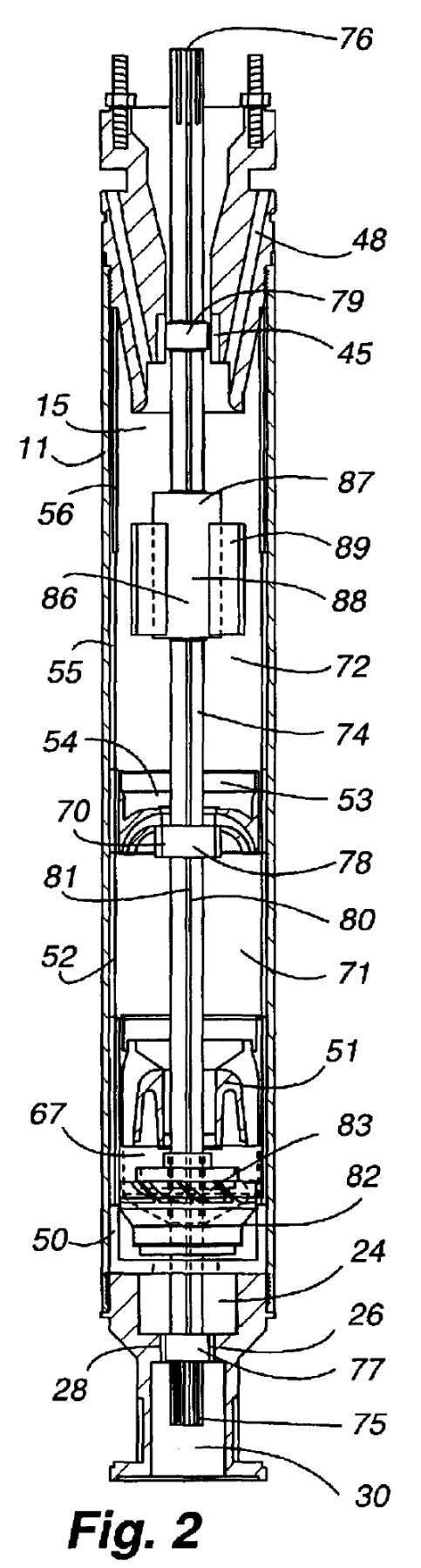
5 Figure 1 depicts a side elevation view of the embodiment and Figure 2 depicts a side cut away view of the separator shown in Figure 1. Ex. 1001, 1: Details of the invention are best understood by way of an explanation of how the separator works. Impeller 83 draws in fluid from the surrounding well through inlet ports 27 and lower diffuser 50. Id. at 4:3 5. The fluid is pumped through upper diffuser 51 to bearing housing 54. Id. at 4:6 8. Bearing housing 54 includes radially-arranged passages 69 (see Ex. 1001, Fig. 6), which restrict fluid flow, causing bearing housing 54 to divide the separator into first and second chambers (chambers 71 and 72). Ex. 1001, 3: As fluid flows through passages 69, the restriction generates a pressure drop in the fluid and causes a rapid expansion of the fluid when it enters chamber 72. Id. at 4: The rapid expansion of the fluid causes the gas and liquid in the fluid to separate. Id. at 4: Bearing housing 54 further includes bearing aperture 68 and intermediate bearing 70, which is mounted in bearing aperture 68. Id. at 3: Within second chamber 72, the fluid is acted on by vortex generator 87. Vortex generator 87, with paddles 89, is connected to shaft 74, which drives both vortex generator 87 and impeller 83 of internal pump 82. Ex. 1001, 3: Vortex generator 87 imparts circular motion on the fluid in chamber 72 and this circular motion serves to centrifugally separate the liquid and gas components of the fluid the heavier liquid moves towards the outside of chamber 72 and the gas moves to the inside of chamber 72. Id. at 4: The liquid passes through liquid outlet ports 47 into the well pump and the gas moves to gas ports 48 and out of the separator at channel 39. Id. at 4:
6 C. Illustrative Claims Claims 1, 9, 10, and 17 of the challenged claims of the 215 patent are independent. Claims 1 and 10 are representative of the claimed subject matter and are reproduced below. comprising: 1. A downhole gas and liquid separator for a well first and second chambers, an internal pump for pumping production fluid through said first chamber, and into said second chamber, means, positioned a between said first and second chambers, for restricting fluid flow to generate a pressure drop in said production fluid and to separate gas and liquid as said production fluid enters said second chamber, and a vortex generator in said second chamber to centrifugally separate said fluid into gas and liquid. 10. A method of separating gas and liquid from production fluid in a well comprising the steps of: providing connected first and second chambers, pumping said production fluid into said first chamber, generating a pressure drop in said production fluid as said production fluid flows from said first chamber to said second chamber, to separate said gas and said liquid, and generating a vortex in said second chamber, to further separate said gas and said liquid. Ex. 1001, 4:55 67, and 5:50 6:2. 6
7 D. The Prior Art Legacy s asserted grounds of unpatentability for the challenged claims of the 215 patent rely on the following references: Carle US 3,300,950 Jan. 31, 1967 Ex Tuzson US 4,088,459 May 9, 1978 Ex Lee ( Lee 193 ) US 6,066,193 May 23, 2000 Ex Lee ( Lee 345 ) US 6,155,345 Dec Ex E. Asserted Grounds of Unpatentability Legacy asserts the following grounds of unpatentability for the challenged claims of the 215 patent. References Basis Claims Challenged Lee (b) 1 4 and 6 17 Lee 193 and Carle 103(a) 5 Tuzson 102(b) 1 4, 8, and Lee 193 and Lee (a) 1 4 and 6 17 II. ANALYSIS A. Claim Construction In an inter partes review, claim terms in an unexpired patent are given their broadest reasonable construction in light of the specification of the patent in which they appear. 37 C.F.R (b); see also In re Cuozzo Speed Techs., LLC, 793 F.3d 1268, 1278 (Fed. Cir. 2015) ( We conclude that Congress implicitly approved the broadest reasonable interpretation 7
8 standard in enacting the AIA. ). Under the broadest reasonable construction standard, claim terms are given their ordinary and customary meaning, as would be understood by one of ordinary skill in the art in the context of the entire disclosure. In re Translogic Tech., Inc., 504 F.3d 1249, 1257 (Fed. Cir. 2007). Also, we are careful not to read a particular embodiment appearing in the written description into the claim if the claim language is broader than the embodiment. See In re Van Geuns, 988 F.2d 1181, 1184 (Fed. Cir. 1993) ( [L]imitations are not to be read into the claims from the specification. ) (citation omitted). Finally, only those terms need be construed that are in controversy and only to the extent necessary to resolve the controversy. Vivid Techs., Inc. v. Am. Sci. & Eng g, Inc., 200 F.3d 795, 803 (Fed. Cir. 1999) (emphasis added). 1. means, positioned a between said first and second chambers, for restricting fluid flow to generate a pressure drop in said production fluid and to separate gas and liquid as said production fluid enters said second chamber Independent claim 1 recites a means, positioned a between said first and second chambers, for restricting fluid flow to generate a pressure drop in said production fluid and to separate gas and liquid as said production fluid enters said second chamber. Ex. 1001, 4: Legacy recognizes that this claim limitation invokes the requirements of 35 U.S.C. 112, paragraph 6, and we agree. 2 See Pet. 20. Accordingly, we construe this limitation by 2 Paragraph 6 of 35 U.S.C. 112 was replaced with newly designated 112(f) when 4(c) of the America Invents Act (ALA), Pub.L. No , took effect on September 16, Because the application resulting in the 8
9 determining the claimed function and identifying the structure disclosed in the specification that corresponds to the means for performing that function. See Kemco Sales, Inc. v. Control Papers Co., 208 F.3d 1352, 1360 (Fed. Cir. 2000); see also In re Donaldson Co., 16 F.3d 1189, 1193 (Fed. Cir. 1994) ( [P]aragraph six applies regardless of the context in which the interpretation of means-plus-function language arises, i.e., whether as part of a patentability determination in the PTO or as part of a validity or infringement determination in a court. ). Legacy identifies three functions associated with the recited means: 1) restricting the production fluid flow; 2) generating a pressure drop in the production fluid; and 3) separating the gas from the liquid. Pet Legacy identifies the structure disclosed in the 215 patent associated with these functions as bearing housing 54 having flow-restricting-passages (that is, passages 69). Id. at 21. Halliburton does not dispute Legacy s position at this time, as Halliburton asserts that [t]he claims are patentable even under [this] proposed construction. Prelim. Resp. 10. We determine, for the purposes of this Decision, that the claimed functions for this limitation are 1) restricting fluid flow to generate a pressure drop in the production fluid, and 2) restricting fluid flow to separate gas and liquid as the production fluid enters said second chamber. Legacy s construction captures this two-fold function, but fails to associate the functions of generating a pressure drop in the production fluid and separating gas and liquid as the production fluid enters the second chamber 215 patent was filed before that date, we refer to the pre-aia version of
10 with restricting fluid flow, but instead improperly identifies restricting production fluid flow as a separate function. We agree with Legacy that the structure associated with these functions is bearing housing 54 with passages internal pump ; diagonally extending passages ; and paddle Legacy provides constructions for the terms internal pump ; diagonally extending passages ; and paddle. Pet We do not construe these terms as their construction is not necessary to resolve the controversy before us, as will be evident from our analysis of the asserted grounds of unpatentability, infra. B. Asserted Grounds of Unpatentability Legacy proposes four grounds of unpatentability for claims 1 17 of the 215 patent: 1) claims 1 4 and 6 17 are unpatentable under 35 U.S.C. 102(b) as anticipated by Lee 193; 2) claim 5 is unpatentable under 35 U.S.C. 103(a) over Lee 193 and Carle; 3) claims 1 4, 8, and are unpatentable under 35 U.S.C. 102(b) as anticipated by Tuzson; and 4) claims 1 4 and 6 17 are unpatentable under 35 U.S.C. 103(a) over Lee 193 and Lee 345. Legacy presents a limitation-by-limitation analysis of the identified claims against the identified references. See Pet Halliburton s Preliminary Response presents detailed arguments countering positions taken in the Petition. See Prelim. Resp
11 1. Claims 1 4 and 6 17 and Lee 193 a. Overview of Lee 193 Lee 193, titled Tapered Flow Gas Separation System, is directed to a submersible pumping system adapted to separate gas from liquids prior to pumping the liquids to the earth s surface. Ex. 1006, 1:6 9. Lee 193 s Figure 2 is reproduced below. 11
12 Figure 2 depicts a vertical elevation partial sectional view of a low flow gas separator. Ex. 1006, 3: Lee 193 s invention is directed to two gas separators a high flow separator and a low flow separator coupled in series. Id. at 2:8 28, Fig. 4. Each of these separators are similar in structure, with the primary difference being that the high flow separator is sized to handle a greater flow rate than the low flow separator. See id. at 6:57 65; see also id., Fig. 3 (depicting a high flow gas separator). The low flow separator includes intake section 26, which includes intake ports 33 and intake grate 34. Ex. 1006, 4: Production fluid is drawn into the separator through the intake ports and grate and into inducer section 28, which includes inducer 40, diffuser 42, and centrifuge 44. Id. at 4: Inducer 40, which is coupled to shaft 46, includes impeller blades and, as shaft 46 rotates, inducer 40 s blades rotate to draw production fluid into the inducer, increasing the fluid s pressure as the fluid moves to diffuser 42. Id. at 5:2 12. Diffuser 42 acts on the production fluid to increase the fluid s pressure. Ex. 1006, 5: Diffuser 42, which is stationary relative to shaft 46, splits the production fluid prior to the fluid encountering centrifuge 44 and may also serve as a bearing support. Id. at 5: In the embodiment of Figure 2, diffuser 42 has a blade-like form. Id. at 5:19. Production fluid leaves diffuser 42 and encounters centrifuge 44, which is coupled to shaft 46 and rotates along with the shaft. Ex. 1006, 5: Centrifuge 44 imparts centrifugal motion on the production fluid, such that the heavier liquid components of the fluid move to the outside of separator and the lighter gaseous components move towards the center of the separator, separating the components. Id. at 5: The separated liquid 12
13 components are directed towards a pump, which pumps the liquid to the earth s surface, and the gaseous components are vented through vent holes 56. Id. at 5: Lee 193 is identified in the Background Art section of the 215 patent as disclosing a powered rotary separator, Ex. 1001, 1:31 33, but Lee 193 did not form the basis of any rejection of claims during prosecution of the application that matured into the 215 patent, see Ex (providing the prosecution history of U.S. Application 10/236,348, which issued as the 215 patent). b. Claims 1 4 and 6 8 Legacy contends that Lee 193 anticipates claim 1 of the 215 patent, including disclosing means, positioned a between said first and second chambers, for restricting fluid flow to generate a pressure drop in said production fluid and to separate gas and liquid as said production fluid enters said second chamber. Pet (relying on the embodiment depicted in Lee 193 s Figure 2). Specifically, Legacy contends that Lee 193 s diffuser 42 satisfies the means-plus-function limitation of claim 1. Legacy asserts that diffuser 42 performs the functions of the recited means-plus-function limitation of claim 1 restricting fluid flow, generating a pressure drop, and separating the gas and liquid in the production fluid. Pet. 27. First, Legacy contends that diffuser 42 restricts flow because, as Lee 193 expressly discloses, diffuser 42 acts to increase the pressure on the production liquid. Id. (quoting Ex. 1006, 5:13 16). Legacy argues that [t]he skilled artisan knows that in order to increase production fluid pressure, the diffuser 42 necessarily has fluid-flow-restricting passages. Id. at 29 (referencing Ex. 1010, Declaration of Dr. Gary Wooley). 13
14 Next, Legacy contends that diffuser 42 generates a pressure drop in the production fluid. Pet. 27. Legacy argues that 1) because inducer 40 pressurizes the fluid in a chamber below diffuser 42 to a pressure greater than the pressure of the fluid in the well-bore annulus from where the fluid is drawn, and 2) because the section of the separator above diffuser 42 that includes centrifuge 44 is vented to the well-bore, meaning that its pressure is less than the pressure in the chamber below diffuser 42, there must be a pressure drop across diffuser 42. Id.; see also id. at ( The increased pressure of the production fluid leaving the diffuser 42, in comparison to the reduced pressure in the vented separation chamber, generates a pressure drop in the production fluid entering the separation chamber. ) (citing Ex. 1010). Finally, Legacy contends that diffuser 42 splits the production fluid into its gas and liquid components prior to the production fluid encountering centrifuge 44. Pet. 27 (referencing Ex. 1006, 5:13 16). We find, on the record before us, that Legacy fails to persuade us that Lee 193 discloses the recited means of claim 1. First, Legacy fails to support its contention that diffuser 42 necessarily restricts flow because it increases pressure in the production fluid. Indeed, a diffuser operates in the exact opposite manner it increases the cross-sectional flow area that a fluid passes through, which causes the fluid to decrease in velocity and increase in pressure. Further, Legacy s general citation to Dr. Wooley s declaration fails to lend support to its position. We are directed to nothing in Dr. Wooley s declaration, other than a conclusory statement that Lee 193 anticipates claim 1, to lend support to the position that the disclosure that diffuser 42 increases fluid pressure necessarily means that diffuser 42 restricts fluid flow. Accordingly, we find that Lee 193 s disclosure that 14
15 fluid pressure increases as it passes through diffuser 42 does not support a finding that diffuser 42 necessarily restricts fluid flow. More significantly, the means-plus-function recitation of claim 1 requires that the corresponding means restrict fluid flow to generate a pressure drop in the production fluid that is, a consequence of the restricted flow is to generate a pressure drop in the fluid. As Legacy recognizes, diffuser 42 causes an increase in the fluid pressure, not a drop in the fluid pressure as the production fluid passes through the diffuser. See Pet. 27; see also Prelim. Resp. 20 ( On the contrary,... the diffuser in Lee 193 increases the pressure of the fluid. ). Legacy s argument that diffuser 42 functions to generate a pressure drop in the production fluid is equally unavailing. As an initial matter, Legacy s position contradicts its position that diffuser 42 increases the pressure in the production fluid. Legacy fails to adequately explain how diffuser 42 can act to both increase pressure in the production fluid and cause a pressure drop across diffuser 42. See Pet. 27. Legacy attempts to avoid this contradiction by asserting that [t]he increased pressure of the production fluid leaving the diffuser 42, in comparison to the reduced pressure in the vented separation chamber, generates a pressure drop in the production fluid entering the separation chamber. Id. at (emphasis added). That is, Legacy argues that the pressure drop function is achieved because the pressure of the production fluid as it leaves diffuser 42 is greater than the pressure in the fluid within the separator section housing centrifuge 44. However, as argued by Legacy, this pressure profile would result in a pressure drop in the fluid across the second chamber, not across diffuser 42. Significantly, the means of claim 1 must function to restrict 15
16 fluid flow to generate a pressure drop in the production fluid that is, the generated pressure drop results from restricting the flow in the means. Finally, Legacy s assertion that diffuser 42 functions to separate the gas and liquid components of the production fluid is not supported by the disclosure of Lee 193. Lee 193 discloses that diffuser 42 splits the flow of the production liquid 32 prior to its encountering the centrifuge 44. Ex. 1006, 5: Legacy fails to adequately explain how this disclosure teaches or suggests that production liquid 32 is split into gas and liquid components, rather than merely split into multiple streams, such as by its blade-like form splitting the stream. See id. at 5:19; see also Prelim. Resp (explaining that Lee 193 merely discloses that the flow of production fluid is split, not that the gaseous and liquid components are separated). A claim is anticipated only if each and every element as set forth in the claim is found, either expressly or inherently described, in a single prior art reference. Verdegaal Bros. v. Union Oil Co. of Cal., 814 F.2d 628, 631 (Fed. Cir. 1987). On the record before us, we conclude that Legacy has failed to show a reasonable likelihood of prevailing in its assertion that Lee 193 anticipates claim 1. Further, we conclude that Legacy has failed to show a reasonable likelihood of prevailing in its assertion that claims 2 4 and 6 8, which depend, directly or indirectly, from claim 1, are anticipated by Lee 193. c. Claim 9 Independent claim 9 does not include the means-plus-function claim limitation of claim 1. Instead, claim 9 recites a fluid flow restricting bearing housing. Ex. 1001, 5:42. Claim 9 further limits the recited bearing housing by functional claim language requiring the housing to restrict[] 16
17 fluid flow to generate a pressure drop in said production fluid and to separate gas and liquid as said production fluid enters said second chamber. Id. at 5: It is well established that features of an apparatus may be recited either structurally or functionally, however, claims directed to an apparatus must be distinguished from the prior art in terms of structure rather than function. In re Schreiber, 128 F.3d 1473, (Fed. Cir. 1997). That is, choosing to define an element functionally, i.e., by what it does, carries with it a risk, as functional language is not given patentable weight if the prior art structure can inherently perform the function. See id. at In asserting that Lee 193 anticipates claim 9, Legacy incorporates its arguments that Lee 193 discloses the means-plus-function claim limitation of claim 1 and the subject matter of claim 6. 3 Pet. 34. We find that this argument fails to demonstrate how Lee 193 s diffuser 42 inherently restricts fluid flow to generate a pressure drop in said production fluid and to separate gas and liquid as said production fluid enters said second chamber as required by claim 9. The functional language of claim 9 is comparable to the functions recited in the means-plus-function limitation of claim 1. As we discussed above, in connection with our analysis of claim 1, Legacy fails to convince us that diffuser 42 performs the functions of the means-plusfunction element of claim 1. By merely incorporating its arguments from claim 1, Legacy similarly fails to convince us that diffuser 42 inherently 3 Claim 6 recites [t]he separator as set forth in claim 2 wherein said means for restricting fluid flow is a bearing housing that has a bearing that stabilizes said shaft. Ex. 1001, 5: Legacy contends that Lee 193 discloses that diffuser 42 satisfies this claim limitation. Pet. 31 (referencing Ex. 1006, 4:66 67). 17
18 satisfies the functional language associated with the bearing housing of claim 9. On the record before us, we conclude that Legacy has failed to show a reasonable likelihood of prevailing in its assertion that Lee 193 anticipates claim 9. d. Claims Independent claim 10 is a method claim that recites, in relevant part, the step of generating a pressure drop in said production fluid as said production fluid flows from said first chamber to said second chamber, to separate said gas and said liquid. Ex. 1001, 5: In supporting its position that Lee 193 anticipates claim 10, Legacy relies on its analysis of the means-plus-function claim limitation of claim 1. Pet. 35. In the analysis of claim 1, Legacy contends that [t]he increased pressure of the production fluid leaving the diffuser 42, in comparison to the reduced pressure in the vented separation chamber, generates a pressure drop in the production fluid entering the separation chamber. Id. at Claim 10 expressly requires generating a pressure drop in the production fluid as the fluid flows from the first chamber to the second chamber not as the fluid flows through the second chamber. As we discussed in connection with our analysis of the means-plus-function claim limitation of claim 1, we find that Lee 193 discloses that the pressure of the production fluid increases as it flows through diffuser 42. By merely incorporating its arguments from claim 1, Legacy fails to convince us that diffuser 42 satisfies the generating a pressure drop step of claim 10, as Legacy fails to explain how the generating a pressure drop step differs from 18
19 the recited pressure drop function of the means-plus-function limitation of claim 1. On the record before us, we conclude that Legacy has failed to show a reasonable likelihood of prevailing in its assertion that Lee 193 anticipates claim 10. Further, we conclude that Legacy has failed to show a reasonable likelihood of prevailing in its assertion that claims 11 16, which depend, directly or indirectly, from claim 10, are anticipated by Lee 193. d. Claim 17 Independent claim 17 is a method claim and recites, in relevant part, the steps of providing connected first and second chambers, a bearing housing between said first and second chambers,... said bearing housing having a plurality of restrictive passages extending helically between said first and second chambers, and passing said production fluid through said passages with said passing generating a pressure drop in said production fluid. Ex. 1001, 6:33 39, 6: In supporting its position that Lee 193 anticipates claim 17, Legacy relies on its analysis of the means-plus-function claim limitation of claim 1 and also its analysis of claims 6 and 7. 4 Pet. 36. As discussed above in connection with our analysis of claims 1, 9, and 10, Legacy fails to demonstrate how Lee 193 s diffuser 42 generates a pressure drop as production fluid is passed through diffuser 42. Indeed, Legacy first argues that diffuser 42 necessarily has restrictive passages 4 Claim 7 recites [t]he separator as set forth in claim 6 wherein said bearing housing has a plurality diagonally extending passages between said first and second chambers that restrict fluid flow and propel said production fluid into said second chamber in a diagonal direction, and thereby initiate vortex generation. Ex. 1001, 5: Legacy contends that Lee 193 s diffuser 42 satisfies the recitation of claim 7. Pet
20 because Lee 193 discloses that production fluid pressure increases as it passes through diffuser 42. See Pet. 32 (analyzing claim 7); see also Pet. 27 ( The diffuser 42 restricts the flow because it acts to increase the pressure on the production liquid. ) (quoting Ex. 1006, 5:13 16). Then, Legacy argues that passing fluid through these restrictive passages results in a pressure drop in the fluid, as required by claim 17. Pet. 37. We are not convinced that Lee 193 s diffuser 42 includes restrictive passages or that passing production fluid through diffuser 42 generates a pressure drop in the fluid. For the reasons discussed above in our analysis of claims 1, 9, and 10, Legacy fails to demonstrate that Lee 193 satisfies the steps of providing a bearing housing having a plurality of restrictive passages extending helically between said first and second chambers and passing said production fluid through said passages with said passing generating a pressure drop in said production fluid as required by claim 17. On the record before us, we conclude that Legacy has failed to show a reasonable likelihood of prevailing in its assertion that Lee 193 anticipates claim Claim 5 over Lee 193 and Carle Claim 5 depends, indirectly, from claim 1 and further recites an upper diffuser between said impeller and said means for restricting fluid flow that directs said production fluid from said impeller toward said means for restricting fluid flow. Ex. 1001, 5:8 11. Legacy contends that claim 5 is obvious over the combination of Lee 193 and Carle. Pet In 20
21 supporting this assertion, Legacy relies on its position that Lee 193 anticipates claim 1. See id. As discussed above in connection with our analysis of claim 1 as anticipated by Lee 193, Legacy fails to persuade us that Lee 193 anticipates claim 1 specifically, Legacy fails to persuade us that Lee 193 includes the recited means-plus function limitation of claim 1. Further, Legacy fails to explain how Carle remedies this deficiency. Accordingly, on the record before us, we conclude that Legacy has failed to show a reasonable likelihood of prevailing in its assertion that claim 5 is unpatentable over Lee 193 and Carle under Ground Claims 1 4, 8, and and Tuzson a. Overview of Tuzson Tuzson, titled Separator, is directed to separators for separating fluids of different densities and especially to gas separators, i.e., a separator for separating the liquid and gaseous phases encountered in oil and water wells and of the type associated with a submersible motor-pump assembly. Ex. 1008, 1:5 10. Tuzson s Figure 1 is reproduced below: 21
22 Figure 1 depicts a longitudinal sectional view of a separator in accordance with Tuzson s invention. Ex. 1008, 2: Tuzson s separator includes three stages: inducer stage 10, impeller stage 12, and centrifugal separator stage 14. Id. at 2: Inducer stage 10 includes helical screw 22, which is connected to central shaft 8, with shaft 8 imparting rotational motion to helical screw 22. Id. at 2: Inducer stage 10 draws production fluid into the separator through inlets 18, pressurizing the fluid and conveying the fluid to impeller stage 12. Id. at 2:
23 Impeller stage 12 includes member 26 with guide vanes 28, member 26 being attached to shaft 8, which imparts rotational motion on member 26. Ex. 1008, 2: Impeller stage 12 imparts rotational motion to the fluid conveyed from inducer stage 10. Id. at 2: Centrifugal stage 14 includes radially directed vanes 36 that join members 32 and 34 to form segmented cavities in centrifugal stage 14. Ex. 1008, 2: Member 32 connects to shaft 8, which causes the assembly of members 32 and 34 and vanes 36 to rotate. Id. at 2: This rotational motion causes the lighter fluid components, such as gas, to flow to the interior of centrifugal stage 14 and the heavier fluid components to flow to the outside of centrifugal stage 14, so that these components may be separated. Id. at 3:6 17. b. Claims 1 4 and 8 Legacy contends that Tuzson anticipates claim 1 of the 215 patent. Pet , As part of this contention, Legacy argues that Tuzson s impeller stage 12 satisfies the means-plus-function limitation of claim 1 specifically arguing that impeller stage 12 performs the same functions as recited in the limitation. First, Legacy contends that impeller stage 12 necessarily restricts the flow of production fluid, because the chamber below impeller stage 12 is pressurized. Pet. 43; see id. at 44 ( Tuzson discloses its inducer screw 22 pressurizes the production fluid to the impeller stage 12, necessarily requiring the impeller stage 12 to provide a flow restriction to maintain the pressure drop across the impeller stage 12. ) (emphasis added). Legacy further asserts that [l]ike Lee 193, and unlike Lee 345, the impeller stage 12 of Tuzson does have fluid-flow-restricting passages. Id. at 44; see also 23
24 id. at 46 ( The skilled artisan knows that the impeller stage 12 necessarily has fluid-flow-restricting passages in order to build pressure entering the impeller stage 12. ). Next, Legacy contends that impeller stage 12 generates a pressure drop in the production fluid. Pet. 43. Legacy argues that the pressure of the production fluid in centrifugal stage 14 is less than the pressure of the fluid in inducer stage 10, because inducer stage 10 pressurizes the fluid above a pressure of the fluid in the well-bore annulus and centrifugal stage 14 is vented to the well-bore annulus. Id. at Legacy asserts that, because of this pressure differential, there must be a pressure drop across impeller stage 12. Id. at 44; see also id. at 46 ( The fluid-flow-restricting impeller stage 12 generates a pressure drop in the production fluid as it flows at a higher pressure... from the inducer stage 10 to a lower pressure... in the separator stage 14. ). Finally, Legacy contends that the impeller stage 12 performs the separating function of the means-plus-function limitation of claim 1. Pet. 44. Legacy argues that impeller stage 12 is a mixed flow impeller and [b]y definition, a mixed flow impeller imparts a helical flow path to the production fluid and thereby centrifugally splits the gas and liquid components prior to encountering the vortex generator in the separator stage 14. Id. (citing Ex. 1010); see also id. at 47 ( The skilled artisan understands that Tuzson by passing the pressurized production fluid through... mixed flow impeller stage 12, separates gas and liquid entering the separator stage 14 by centrifugally urging heavier liquid-laden production liquid radially outward and the lighter gas-laden production fluid radially inward. ). 24
25 We find, on the record before us, that Legacy fails to persuade us that Tuzson discloses the recited means of claim 1 and specifically that impeller stage 12 performs the recited functions. First, Legacy fails to support its contention that impeller stage 12 necessarily restricts flow because inducer stage 10 increases pressure in a chamber below impeller stage 12. Legacy fails to explain why the pressure of the production fluid does not result from a resistance to flow of the fluid within inducer stage 10, such as by the helical screw 22, inlet 30, or the interior of housing 24 Legacy offers one possible reason for the pressure increase, but fails to demonstrate why the proffered reason is necessarily the case. To establish inherency, the [] evidence must make clear that the missing descriptive matter is necessarily present in the thing described in the reference, and that it would be so recognized by persons of ordinary skill. In re Robertson, 169 F.3d 743, 745 (Fed. Cir. 1999) (citations omitted). Inherency, however, may not be established by probabilities or possibilities. The mere fact that a certain thing may result from a given set of circumstances is not sufficient. Id. Next, Legacy s argument that impeller stage 12 functions to generate a pressure drop in the production fluid is also unpersuasive. Legacy s position demonstrates that there is a pressure drop across centrifugal stage 14, not a pressure drop across impeller stage 12. As Halliburton points out, guide vanes 28 of the impeller stage 12 shown in the figure perform the well-known function of an impeller, which is to pressurize the fluid as it pushes it upstream. Prelim. Resp. 36. Legacy fails to explain adequately why impeller stage 12 does not maintain or increase the pressure of the production fluid leaving inducer stage 10, with the pressure drop occurring 25
26 from the point the fluid enters centrifugal stage 14 and exits through passages 46. Finally, Legacy fails to explain adequately how the impeller of impeller stage 12 constitutes a flow restriction. As Legacy contends, the separation function is accomplished by the rotational motion of impeller stage 12. See Pet. 44. Claim 1 requires that the separation function be a result of restricting fluid flow and Legacy fails to explain how the rotational motion restricts flow. Indeed, as Halliburton points out, an impeller pushes fluid through a system that is, promotes flow rather than restricts flow. See Prelim. Resp. 36. On the record before us, we conclude that Legacy has failed to show a reasonable likelihood of prevailing in its assertion that Tuzson anticipates claim 1. Further, we conclude that Legacy has failed to show a reasonable likelihood of prevailing in its assertion that claims 2 4 and 8, which depend, directly or indirectly, from claim 1, are anticipated by Tuzson. c. Claims Independent claim 10 is a method claim that recites, in relevant part, the step of generating a pressure drop in said production fluid as said production fluid flows from said first chamber to said second chamber, to separate said gas and said liquid. Ex. 1001, 5: In supporting its position that Tuzson anticipates claim 10, Legacy relies on its analysis of Tuzson with respect to claim 1, including the means-plus-function claim limitation of claim 1. Pet. 50. Specifically, Legacy references its analysis of the means-plus-function claim limitation of claim 1 for the generating a pressure drop step of claim 10. See id. (referencing the analysis of claim 1(c) for claim limitation 10(c)). 26
27 As we discussed in connection with our analysis of the means-plusfunction claim limitation of claim 1 with respect to Tuzson, we find that Legacy fails to persuade us that Tuzson s impeller stage 12 satisfies the claim limitation, including performing the function of restricting fluid flow to generate a pressure drop in the production fluid as required by claim 1. By merely incorporating its arguments from claim 1, Legacy fails to convince us that impeller stage 12 satisfies the generating a pressure drop step of claim 10, as Legacy fails to explain how the generating a pressure drop step differs from the recited pressure drop function of the means-plusfunction limitation of claim 1. On the record before us, we conclude that Legacy has failed to show a reasonable likelihood of prevailing in its assertion that Tuzson anticipates claim 10. Further, we conclude that Legacy has failed to show a reasonable likelihood of prevailing in its assertion that claims 11 16, which depend, directly or indirectly, from claim 10, are anticipated by Tuzson. 4. Claims 1 4 and 6 17 over Lee 193 and Lee 345 In contending that claims 1 4 and 6 17 of the 215 patent are unpatentable over Lee 193 and Lee 345, Legacy relies, in part, on its contention that Lee 193 discloses certain claim limitations of independent claims 1, 9, 10, and 17. See Pet Specifically, Legacy relies on Lee 193 for disclosing 1) the means-plus-function claim limitation of claim 1; 2) the fluid flow restricting bearing housing claim limitation of claim 9; 3) the generating a pressure drop step of claim 10; and 4) the providing a bearing housing with restrictive passages step and the passing the production fluid through the passages step of claim 17. Id. at (regarding claim 27
28 limitation 1(c)), 57 (regarding claim limitation 9(h)), 58 (regarding claim limitations 10(c), 17(b), and 17(e)). As discussed above in connection with our analysis of independent claims 1, 9, 10, and 17 as anticipated by Lee 193, we find that Legacy fails to demonstrate that Lee 193 discloses the recited subject matter relied on by Legacy for this ground. Accordingly, on the record before us, we conclude that Legacy has failed to show a reasonable likelihood of prevailing in its assertion that claims 1 4 and 6 17 are unpatentable over Lee 193 and Lee 345. III. CONCLUSION For the foregoing reasons, we determine that the information presented in the Petition fails to establish a reasonable likelihood that Legacy would prevail in showing that claims 1 17 of the 215 patent are unpatentable. IV. ORDERS After due consideration of the record before us, it is: ORDERED that the Petition is denied as to all challenged claims and no trial is instituted. 28
29 For PETITIONER: Mitchell K. McCarthy HALL ESTILL ATTORNEYS AT LAW For PATENT OWNER: Paul Morico Thomas Rooney BAKER BOTTS LLP 29
Paper No Entered: July 19, 2017 UNITED STATES PATENT AND TRADEMARK OFFICE BEFORE THE PATENT TRIAL AND APPEAL BOARD
 Trials@uspto.gov Paper No. 8 571.272.7822 Entered: July 19, 2017 UNITED STATES PATENT AND TRADEMARK OFFICE BEFORE THE PATENT TRIAL AND APPEAL BOARD TOPGOLF INTERNATIONAL, INC., Petitioner, v. AMIT AGARWAL,
Paper Entered August 30, 2018 UNITED STATES PATENT AND TRADEMARK OFFICE BEFORE THE PATENT TRIAL AND APPEAL BOARD
 Trials@uspto.gov Paper 21 571-272-7822 Entered August 30, 2018 UNITED STATES PATENT AND TRADEMARK OFFICE BEFORE THE PATENT TRIAL AND APPEAL BOARD TAYLOR MADE GOLF COMPANY, INC., Petitioner, v. PARSONS
IN THE UNITED STATES PATENT AND TRADEMARK OFFICE BEFORE THE PATENT TRIAL AND APPEAL BOARD D R BURTON HEALTHCARE LLC. Petitioner
 IN THE UNITED STATES PATENT AND TRADEMARK OFFICE BEFORE THE PATENT TRIAL AND APPEAL BOARD D R BURTON HEALTHCARE LLC Petitioner v. TRUDELL MEDICAL INTERNATIONAL Patent Owner Patent No. U.S. 9,808,588 Filing
United States Court of Appeals for the Federal Circuit
 Page 1 of 5 NOTE: Pursuant to Fed. Cir. R. 47.6, this disposition is not citable as precedent. It is a public record. This disposition will appear in tables published periodically. United States Court
(12) United States Patent (10) Patent No.: US 6,834,776 B1
 United States Patent (10) Patent No.: US 6,834,776 B1") USOO6834776B1 (12) United States Patent (10) Patent No.: US 6,834,776 B1 Corvese (45) Date of Patent: Dec. 28, 2004 (54) TENNIS BALL RETRIEVING DEVICE 5,125,654 A 6/1992 Bruno... 473/460 (75) Inventor:
USOO6834776B1 (12) United States Patent (10) Patent No.: US 6,834,776 B1 Corvese (45) Date of Patent: Dec. 28, 2004 (54) TENNIS BALL RETRIEVING DEVICE 5,125,654 A 6/1992 Bruno... 473/460 (75) Inventor:
BALL ACTUATED DOWNHOLE TOOL BACKGROUND
 BALL ACTUATED DOWNHOLE TOOL BACKGROUND Wellbore tools are known that are actuated by actuator balls. A downhole actuator ball is conveyed downhole to actuate one or more wellbore tools, as by landing in
United States Patent (19) 11 Patent Number: 5,493,591 Kadowaki 45 Date of Patent: Feb. 20, 1996
 11 Patent Number: 5,493,591 Kadowaki 45 Date of Patent: Feb. 20, 1996") USOO5493591A United States Patent (19) 11 Patent Number: Kadowaki 45 Date of Patent: Feb. 20, 1996 54 INTERNAL PUMPFOR NUCLEAR 3,950,220 4/1976 Holz... 376/.391 REACTORS FOREIGN PATENT DOCUMENTS 75) Inventor:
USOO5493591A United States Patent (19) 11 Patent Number: Kadowaki 45 Date of Patent: Feb. 20, 1996 54 INTERNAL PUMPFOR NUCLEAR 3,950,220 4/1976 Holz... 376/.391 REACTORS FOREIGN PATENT DOCUMENTS 75) Inventor:
(12) Patent Application Publication (10) Pub. No.: US 2013/ A1
 Patent Application Publication (10) Pub. No.: US 2013/ A1") US 2013 0186486A1 (19) United States (12) Patent Application Publication (10) Pub. No.: US 2013/0186486A1 Ding (43) Pub. Date: Jul. 25, 2013 (54) SYSTEM FOR AND METHOD OF (52) U.S. Cl. MONITORING FLOW
US 2013 0186486A1 (19) United States (12) Patent Application Publication (10) Pub. No.: US 2013/0186486A1 Ding (43) Pub. Date: Jul. 25, 2013 (54) SYSTEM FOR AND METHOD OF (52) U.S. Cl. MONITORING FLOW
Neal L. Slifkin, Paul J. Yesawich, III, Harris Beach LLP, Pittsford, NY, for Plaintiff.
 United States District Court, W.D. New York. IZZO GOLF, INC, Plaintiff. v. TAYLOR MADE GOLF COMPANY, INC., d/b/a Taylor Made-Adidas Golf Company, Defendant. Taylor Made Golf Company, Inc., d/b/a Taylor
@ -4 Inventors: Daniel L Mensink 3578 Gregory Lane Lynchburg, Virginia 24503
 S-73,657 LO 09 0 CO _H O_ O0 I 0 < I X j NOZZLE MIXING APPARATUS @ -4 Inventors: Daniel L Mensink 3578 Gregory Lane Lynchburg, Virginia 24503 D < < m m DISCLAIMER ZX H H N0 NZ This report was prepared
(12) United States Patent (10) Patent No.: US 6,524,267 B1
 United States Patent (10) Patent No.: US 6,524,267 B1") USOO6524267B1 (12) United States Patent (10) Patent No.: US 6,524,267 B1 Gremel et al. 45) Date of Patent: Feb. 25, 2003 9 (54) VENOUS FILTER FOR ASSISTED VENOUS (56) References Cited RETUR N U.S. PATENT
USOO6524267B1 (12) United States Patent (10) Patent No.: US 6,524,267 B1 Gremel et al. 45) Date of Patent: Feb. 25, 2003 9 (54) VENOUS FILTER FOR ASSISTED VENOUS (56) References Cited RETUR N U.S. PATENT
The government moves for reconsideration of part of my Opinion and Order of September
 UNITED STATES DISTRICT COURT SOUTHERN DISTRICT OF NEW YORK ---------------------------------------------------------------x AMERICAN CIVIL LIBERTIES UNION, et al., : : ORDER DENYING Plaintiffs, : MOTION
The below identified patent application is available for licensing. Requests for information should be addressed to:
 DEPARTMENT OF THE NAVY OFFICE OF COUNSEL NAVAL UNDERSEA WARFARE CENTER DIVISION 1176 HOWELL STREET NEWPORT Rl 02841-1708 IN REPLY REFER TO Attorney Docket No. 300170 20 March 2018 The below identified
AMERICAN SEATING COMPANY,
 United States District Court, D. Minnesota. CADDY PRODUCTS, INC, Plaintiff. v. AMERICAN SEATING COMPANY, Defendant. Civil No. 05-800 (JRT/FLN) April 4, 2008. Richard G. Jensen and Dyanna L. Street, Fabyanske
Ice skate blade alignment mechanism
 Iowa State University Patents Iowa State University Research Foundation, Inc. 8-11-1992 Ice skate blade alignment mechanism Leon E. Girard Iowa State University Patrick E. Patterson Iowa State University
N3% (12) United States Patent. NNéré. (10) Patent No.: US 7, B2. Rossiter (45) Date of Patent: Nov. 20, 2007
 United States Patent. NNéré. (10) Patent No.: US 7, B2. Rossiter (45) Date of Patent: Nov. 20, 2007") (12) United States Patent US007298.473B2 (10) Patent o.: US 7,298.473 B2 Rossiter (45) Date of Patent: ov. 20, 2007 (54) SPECTROSCOPY CELL 4,587,835 A 5/1986 Adams 4,674,876 A 6/1987 Rossiter... 356,244
(12) United States Patent US007298.473B2 (10) Patent o.: US 7,298.473 B2 Rossiter (45) Date of Patent: ov. 20, 2007 (54) SPECTROSCOPY CELL 4,587,835 A 5/1986 Adams 4,674,876 A 6/1987 Rossiter... 356,244
USOO A United States Patent (19) 11 Patent Number: 5,893,786 Stevens 45 Date of Patent: Apr. 13, 1999
 11 Patent Number: 5,893,786 Stevens 45 Date of Patent: Apr. 13, 1999") III IIII USOO589.3786A United States Patent (19) 11 Patent Number: Stevens 45 Date of Patent: Apr. 13, 1999 54 AUTOMATIC TELESCOPING BOUYANT 5,582,127 12/1996 Willis et al.... 116/210 IDENTIFICATION DEVICE
III IIII USOO589.3786A United States Patent (19) 11 Patent Number: Stevens 45 Date of Patent: Apr. 13, 1999 54 AUTOMATIC TELESCOPING BOUYANT 5,582,127 12/1996 Willis et al.... 116/210 IDENTIFICATION DEVICE
United States Court of Appeals for the Federal Circuit
 United States Court of Appeals for the Federal Circuit 02-1177, -1178, -1227 FLEUR T. TEHRANI, Ph.D., P.E., v. Plaintiff-Appellee, HAMILTON MEDICAL, INC. and HAMILTON MEDICAL, A.G., Defendants-Appellants.
(12) Patent Application Publication (10) Pub. No.: US 2014/ A1
 Patent Application Publication (10) Pub. No.: US 2014/ A1") (19) United States US 2014036O734A1 (12) Patent Application Publication (10) Pub. No.: US 2014/0360734 A1 DOane et al. (43) Pub. Date: Dec. 11, 2014 (54) PACKER SETTING MECHANISM (71) Applicants: James
(19) United States US 2014036O734A1 (12) Patent Application Publication (10) Pub. No.: US 2014/0360734 A1 DOane et al. (43) Pub. Date: Dec. 11, 2014 (54) PACKER SETTING MECHANISM (71) Applicants: James
E2IB (7/02 ( ) (52) U.S. Cl /19: 464/155 (58) Field of Classification Search / , 175/325.6
 (52) U.S. Cl /19: 464/155 (58) Field of Classification Search / , 175/325.6") US007 186182B2 (12) United States Patent Wenzel et al. (10) Patent No.: (45) Date of Patent: US 7,186,182 B2 Mar. 6, 2007 (54) DRIVE LINE FOR DOWN HOLE MUD MOTOR (76) Inventors: William R. Wenzel, 1738
US007 186182B2 (12) United States Patent Wenzel et al. (10) Patent No.: (45) Date of Patent: US 7,186,182 B2 Mar. 6, 2007 (54) DRIVE LINE FOR DOWN HOLE MUD MOTOR (76) Inventors: William R. Wenzel, 1738
UNITED STATES PATENT AND TRADEMARK OFFICE IN THE UNITED STATES PATENT TRIAL AND APPEAL BOARD. PRAXAIR DISTRIBUTION, INC.
 UNITED STATES PATENT AND TRADEMARK OFFICE IN THE UNITED STATES PATENT TRIAL AND APPEAL BOARD PRAXAIR DISTRIBUTION, INC. Petitioner v. INO THERAPEUTICS, LLC. d/b/a IKARIA, INC. Patent Owner CASE IPR: UNASSIGNED
The Discussion of this exercise covers the following points: Pumps Basic operation of a liquid pump Types of liquid pumps The centrifugal pump.
 Exercise 2-3 Centrifugal Pumps EXERCISE OBJECTIVE In this exercise, you will become familiar with the operation of a centrifugal pump and read its performance chart. You will also observe the effect that
Lightweight portable training device to simulate kayaking
 University of Central Florida UCF Patents Patent Lightweight portable training device to simulate kayaking 12-7-2010 Ronald Eaglin University of Central Florida Find similar works at: http://stars.library.ucf.edu/patents
Tradition & Technology
 Gaterotor Support Gaterotor Single Screw Compressors Design & Operation Bearing Bearings Main Screw Parallex Slide System The VSM Single Screw Compressor has one main rotor and two gaterotors. All bearings
TEPZZ 7_687ZA_T EP A1 (19) (11) EP A1 (12) EUROPEAN PATENT APPLICATION. (43) Date of publication: Bulletin 2014/15
 (11) EP A1 (12) EUROPEAN PATENT APPLICATION. (43) Date of publication: Bulletin 2014/15") (19) TEPZZ 7_687ZA_T (11) EP 2 716 870 A1 (12) EUROPEAN PATENT APPLICATION (43) Date of publication: 09.04.2014 Bulletin 2014/15 (51) Int Cl.: F01D 5/20 (2006.01) (21) Application number: 13187418.2 (22)
(19) TEPZZ 7_687ZA_T (11) EP 2 716 870 A1 (12) EUROPEAN PATENT APPLICATION (43) Date of publication: 09.04.2014 Bulletin 2014/15 (51) Int Cl.: F01D 5/20 (2006.01) (21) Application number: 13187418.2 (22)
(12) United States Patent (10) Patent No.: US 6,923,737 B1
 United States Patent (10) Patent No.: US 6,923,737 B1") USOO6923737B1 (12) United States Patent (10) Patent No.: US 6,923,737 B1 Walker (45) Date of Patent: Aug. 2, 2005 (54) BASEBALL SWING TRAINING APPARATUS 3,115,129 A 12/1963 Merriman... 124/5 3,115,342
USOO6923737B1 (12) United States Patent (10) Patent No.: US 6,923,737 B1 Walker (45) Date of Patent: Aug. 2, 2005 (54) BASEBALL SWING TRAINING APPARATUS 3,115,129 A 12/1963 Merriman... 124/5 3,115,342
United States Patent (19) Santos
 Santos") United States Patent (19) Santos 54). STATIONARY EXERCISE BICYCLE 76 Inventor: James P. Santos, 223 Rockingstone, Larchmont, N.Y. 10538 (21) Appl. No.: 748,198 22 Filed: Dec. 7, 1976 51) Int. C.... A633
United States Patent (19) Santos 54). STATIONARY EXERCISE BICYCLE 76 Inventor: James P. Santos, 223 Rockingstone, Larchmont, N.Y. 10538 (21) Appl. No.: 748,198 22 Filed: Dec. 7, 1976 51) Int. C.... A633
exercising facility (14), when the arms of the person are to
, when the arms of the person are to") USOO5906563A United States Patent (19) 11 Patent Number: 5,906,563 Pittari (45) Date of Patent: May 25, 1999 54) DUAL EXERCISE BIKE 5,284.462 2/1994 Olschansky et al.... 482/64 5,342,262 8/1994 Hansen......
USOO5906563A United States Patent (19) 11 Patent Number: 5,906,563 Pittari (45) Date of Patent: May 25, 1999 54) DUAL EXERCISE BIKE 5,284.462 2/1994 Olschansky et al.... 482/64 5,342,262 8/1994 Hansen......
PATENT AGENT EXAMINATION PAPER A
 Page 1 of 21 PATENT AGENT EXAMINATION PAPER A 2009 Dear Candidate, Paper A is a patent drafting exercise in which the candidate is requested to prepare a full patent specification, with significant weight
United States District Court, E.D. Michigan, Southern Division.
 United States District Court, E.D. Michigan, Southern Division. HAYES LEMMERZ INTERNATIONAL, INC, Plaintiff. v. KUHL WHEELS, LLC and Epilogics Group, Defendants. No. 03-CV-70181-DT April 25, 2007. Stephen
(12) United States Patent (10) Patent No.: US 6,311,857 B1
 United States Patent (10) Patent No.: US 6,311,857 B1") USOO6311857B1 (12) United States Patent (10) Patent No.: US 6,311,857 B1 Al-Darraii (45) Date of Patent: Nov. 6, 2001 (54) STAND USING HOCKEY STICK SUPPORTS 5,848,716 12/1998 Waranius... 211/85.7 X 6,073,783
USOO6311857B1 (12) United States Patent (10) Patent No.: US 6,311,857 B1 Al-Darraii (45) Date of Patent: Nov. 6, 2001 (54) STAND USING HOCKEY STICK SUPPORTS 5,848,716 12/1998 Waranius... 211/85.7 X 6,073,783
US B 1. (12) United States Patent Kamio. (10) Patent No.: US 8,240,976 Bl
 United States Patent Kamio. (10) Patent No.: US 8,240,976 Bl") 111111 1111111111111111111111111111111111111111111111111111111111111 US008240976B 1 (12) United States Patent Kamio (10) Patent No.: US 8,240,976 Bl (45) Date of Patent: Aug. 14,2012 (54) METHODS AND APPARATUS
111111 1111111111111111111111111111111111111111111111111111111111111 US008240976B 1 (12) United States Patent Kamio (10) Patent No.: US 8,240,976 Bl (45) Date of Patent: Aug. 14,2012 (54) METHODS AND APPARATUS
United States Patent (19) Widecrantz et al.
 Widecrantz et al.") United States Patent (19) Widecrantz et al. 54 76 22) 21 (52) (51) 58 56 ONE WAY WALVE PRESSURE PUMP TURBINE GENERATOR STATION Inventors: Kaj Widecrantz, P.O. Box 72; William R. Gatton, P.O. Box 222, both
United States Patent (19) Widecrantz et al. 54 76 22) 21 (52) (51) 58 56 ONE WAY WALVE PRESSURE PUMP TURBINE GENERATOR STATION Inventors: Kaj Widecrantz, P.O. Box 72; William R. Gatton, P.O. Box 222, both
Exercise 4-2. Centrifugal Pumps EXERCISE OBJECTIVE DISCUSSION OUTLINE DISCUSSION. Pumps
 Exercise 4-2 Centrifugal Pumps EXERCISE OBJECTIVE Familiarize yourself with the basics of liquid pumps, specifically with the basics of centrifugal pumps. DISCUSSION OUTLINE The Discussion of this exercise
(12) United States Patent
 United States Patent") (12) United States Patent Parkinson et al. USOO6776732B2 (10) Patent No.: (45) Date of Patent: Aug. 17, 2004 (54) SIMULATED TENNIS BALL TRAJECTORY & DELIVERY SYSTEM (76) Inventors: Paul Parkinson, 2655
(12) United States Patent Parkinson et al. USOO6776732B2 (10) Patent No.: (45) Date of Patent: Aug. 17, 2004 (54) SIMULATED TENNIS BALL TRAJECTORY & DELIVERY SYSTEM (76) Inventors: Paul Parkinson, 2655
(12) United States Patent (10) Patent No.: US 8,128,344 B2
 United States Patent (10) Patent No.: US 8,128,344 B2") USOO8128344B2 (12) United States Patent (10) Patent No.: McGovern et al. (45) Date of Patent: Mar. 6, 2012 (54) METHODS AND APPARATUS INVOLVING 6,361,274 B1 3/2002 Kreis et al. SHROUD COOLING 6,406.256
USOO8128344B2 (12) United States Patent (10) Patent No.: McGovern et al. (45) Date of Patent: Mar. 6, 2012 (54) METHODS AND APPARATUS INVOLVING 6,361,274 B1 3/2002 Kreis et al. SHROUD COOLING 6,406.256
(12) United States Patent (10) Patent No.: US 7,052,424 B2
 United States Patent (10) Patent No.: US 7,052,424 B2") US007052424B2 (12) United States Patent (10) Patent No.: US 7,052,424 B2 Kabrich et al. (45) Date of Patent: May 30, 2006 (54) CANTILEVER TOOTH SPROCKET 3,173,301 A * 3/1965 Miller... 474,163 3,899,219
US007052424B2 (12) United States Patent (10) Patent No.: US 7,052,424 B2 Kabrich et al. (45) Date of Patent: May 30, 2006 (54) CANTILEVER TOOTH SPROCKET 3,173,301 A * 3/1965 Miller... 474,163 3,899,219
(12) Patent Application Publication (10) Pub. No.: US 2005/ A1
 Patent Application Publication (10) Pub. No.: US 2005/ A1") (19) United States US 20050272546A1 (12) Patent Application Publication (10) Pub. No.: US 2005/0272546A1 Reiter (43) Pub. Date: Dec. 8, 2005 (54) RIVETED SPROCKETASSEMBLY (75) Inventor: Markus Reiter,
(19) United States US 20050272546A1 (12) Patent Application Publication (10) Pub. No.: US 2005/0272546A1 Reiter (43) Pub. Date: Dec. 8, 2005 (54) RIVETED SPROCKETASSEMBLY (75) Inventor: Markus Reiter,
United States Patent (19) Salandre
 Salandre") United States Patent (19) Salandre 11) Patent Number: 45) Date of Patent: Jun. 19, 1990 (54 HANDGUN HOLSTER AND RETENTION APPARATUS 76 Inventor: Stephen M. Salandre, P.O. Box 130, Taos, N. Mex. 87571 (21)
United States Patent (19) Salandre 11) Patent Number: 45) Date of Patent: Jun. 19, 1990 (54 HANDGUN HOLSTER AND RETENTION APPARATUS 76 Inventor: Stephen M. Salandre, P.O. Box 130, Taos, N. Mex. 87571 (21)
Central Reexamination Unit (CRU)
") Patent Public Advisory Committee Quarterly Meeting Central Reexamination Unit (CRU) John Cottingham Director, Central Reexamination Unit May 5, 2016 Current Makeup of the CRU 1 SES Group Director 10 Supervisory
Patent Public Advisory Committee Quarterly Meeting Central Reexamination Unit (CRU) John Cottingham Director, Central Reexamination Unit May 5, 2016 Current Makeup of the CRU 1 SES Group Director 10 Supervisory
Inventor Michael M. Canadav NOTICE
 Serial No. 514.576 Filing Date 14 August 1995 Inventor Michael M. Canadav NOTICE The above identified patent application is available for licensing. Requests for information should be addressed to: Äppsovsö
UNITED STATES PATENT AND TRADEMARK OFFICE BEFORE THE PATENT TRIAL AND APPEAL BOARD. FISHER & PAYKEL HEALTHCARE LIMITED, Petitioner
 By: Filed on behalf of: Filed: July 14, 2017 Fisher & Paykel Healthcare Limited Brenton R. Babcock Benjamin J. Everton KNOBBE, MARTENS, OLSON & BEAR, LLP 2040 Main Street, 14th Floor Irvine, CA 92614 Tel.:
(12) United States Patent
 United States Patent") USO09725888B2 (12) United States Patent Cellemme et al. (10) Patent No.: (45) Date of Patent: Aug. 8, 2017 (54) (71) (72) (73) (*) (21) (22) (65) (63) (51) (52) (58) DUAL CHECK BACKFLOW PREVENTER Applicant:
USO09725888B2 (12) United States Patent Cellemme et al. (10) Patent No.: (45) Date of Patent: Aug. 8, 2017 (54) (71) (72) (73) (*) (21) (22) (65) (63) (51) (52) (58) DUAL CHECK BACKFLOW PREVENTER Applicant:
Device for atomizing a liquid
 Page 1 of 6 Device for atomizing a liquid Abstract ( 5 of 5 ) United States Patent 4,504,014 Leuning March 12, 1985 A device (10) for atomizing a liquid is disclosed. The device (10) includes a sprayhead
Semi-automatic firearms
 United States Patent 4,335,643 Gal June 22, 1982 Semi-automatic firearms Abstract Disclosed is a semi-automatic firearm which has a configuration generally similar to a known form of submachine gun insofar
(12) Patent Application Publication (10) Pub. No.: US 2016/ A1
 Patent Application Publication (10) Pub. No.: US 2016/ A1") (19) United States US 2016.0023O86A1 (12) Patent Application Publication (10) Pub. No.: US 2016/0023086 A1 Aamodt (43) Pub. Date: Jan. 28, 2016 (54) SKATEBOARD TRUCKWITH OFFSET (52) U.S. Cl. BUSHING SEATS
(19) United States US 2016.0023O86A1 (12) Patent Application Publication (10) Pub. No.: US 2016/0023086 A1 Aamodt (43) Pub. Date: Jan. 28, 2016 (54) SKATEBOARD TRUCKWITH OFFSET (52) U.S. Cl. BUSHING SEATS
UNITED STATES PATENT AND TRADEMARK OFFICE IN THE UNITED STATES PATENT TRIAL AND APPEAL BOARD. PRAXAIR DISTRIBUTION, INC.
 UNITED STATES PATENT AND TRADEMARK OFFICE IN THE UNITED STATES PATENT TRIAL AND APPEAL BOARD PRAXAIR DISTRIBUTION, INC. Petitioner v. INO THERAPEUTICS, LLC. d/b/a IKARIA, INC. Patent Owner CASE IPR: UNASSIGNED
TEPZZ 6Z4795A T EP A2 (19) (11) EP A2 (12) EUROPEAN PATENT APPLICATION. (43) Date of publication: Bulletin 2013/25
 (11) EP A2 (12) EUROPEAN PATENT APPLICATION. (43) Date of publication: Bulletin 2013/25") (19) TEPZZ 6Z479A T (11) EP 2 604 79 A2 (12) EUROPEAN PATENT APPLICATION (43) Date of publication: 19.06.2013 Bulletin 2013/2 (1) Int Cl.: F01D /18 (2006.01) (21) Application number: 12194748. (22) Date
(19) TEPZZ 6Z479A T (11) EP 2 604 79 A2 (12) EUROPEAN PATENT APPLICATION (43) Date of publication: 19.06.2013 Bulletin 2013/2 (1) Int Cl.: F01D /18 (2006.01) (21) Application number: 12194748. (22) Date
Ulllted States Patent [19] [11] Patent Number: 5,863,267. Ch0i [45] Date of Patent: Jan. 26, 1999
![Ulllted States Patent [19] [11] Patent Number: 5,863,267. Ch0i [45] Date of Patent: Jan. 26, 1999](/thumbs/96/126860656.jpg "Ulllted States Patent [19] [11] Patent Number: 5,863,267. Ch0i [45] Date of Patent: Jan. 26, 1999") USOO5863267A Ulllted States Patent [19] [11] Patent Number: 5,863,267 Ch0i [45] Date of Patent: Jan. 26, 1999 [54] RACKET DEVICE AND ASSOCIATED FOREIGN PATENT DOCUMENTS METHOD OF STRINGINGA RACKET 582861
USOO5863267A Ulllted States Patent [19] [11] Patent Number: 5,863,267 Ch0i [45] Date of Patent: Jan. 26, 1999 [54] RACKET DEVICE AND ASSOCIATED FOREIGN PATENT DOCUMENTS METHOD OF STRINGINGA RACKET 582861
(12) United States Patent (10) Patent No.: US 6,601,826 B1
 United States Patent (10) Patent No.: US 6,601,826 B1") USOO66O1826B1 (12) United States Patent (10) Patent No.: Granata (45) Date of Patent: Aug. 5, 2003 (54) LOW-LEVEL LIFT 4,858,888 A 8/1989 Cruz et al.... 254/122 5,192,053 A * 3/1993 Sehlstedt... 254/122
USOO66O1826B1 (12) United States Patent (10) Patent No.: Granata (45) Date of Patent: Aug. 5, 2003 (54) LOW-LEVEL LIFT 4,858,888 A 8/1989 Cruz et al.... 254/122 5,192,053 A * 3/1993 Sehlstedt... 254/122
Three-position-jacquard machine
 ( 1 of 27264 ) United States Patent 6,581,646 Dewispelaere June 24, 2003 Three-position-jacquard machine Abstract A three-position shed-forming device with a shed-forming element (10);(60,70) in connection
(Refer Slide Time: 2:16)
") Fluid Machines. Professor Sankar Kumar Som. Department Of Mechanical Engineering. Indian Institute Of Technology Kharagpur. Lecture-23. Diffuser and Cavitation. Good morning and welcome you all to this
Fluid Machines. Professor Sankar Kumar Som. Department Of Mechanical Engineering. Indian Institute Of Technology Kharagpur. Lecture-23. Diffuser and Cavitation. Good morning and welcome you all to this
(12) Patent Application Publication (10) Pub. No.: US 2015/ A1
 Patent Application Publication (10) Pub. No.: US 2015/ A1") US 2015O129357A1 (19) United States (12) Patent Application Publication (10) Pub. No.: US 2015/0129357 A1 ROth (43) Pub. Date: May 14, 2015 (54) GUIDED TYPE FALL ARRESTER - BODY (52) U.S. Cl. CONTROL SYSTEM
US 2015O129357A1 (19) United States (12) Patent Application Publication (10) Pub. No.: US 2015/0129357 A1 ROth (43) Pub. Date: May 14, 2015 (54) GUIDED TYPE FALL ARRESTER - BODY (52) U.S. Cl. CONTROL SYSTEM
(12) United States Patent
 United States Patent") (12) United States Patent Dickinson et al. USOO6398197B1 (10) Patent No.: US 6,398,197 B1 (45) Date of Patent: Jun. 4, 2002 (54) WATER CHAMBER (75) Inventors: Philip John Dickinson; David Wixey, both of
(12) United States Patent Dickinson et al. USOO6398197B1 (10) Patent No.: US 6,398,197 B1 (45) Date of Patent: Jun. 4, 2002 (54) WATER CHAMBER (75) Inventors: Philip John Dickinson; David Wixey, both of
USOO6O76829A United States Patent (19) 11 Patent Number: 6,076,829 Oblack (45) Date of Patent: Jun. 20, 2000
 11 Patent Number: 6,076,829 Oblack (45) Date of Patent: Jun. 20, 2000") USOO6O76829A United States Patent (19) 11 Patent Number: 6,076,829 Oblack (45) Date of Patent: Jun. 20, 2000 54) BALL THROWINGAPPARATUS AND 3,428,036 2/1969 Parker. METHOD 3,589,349 6/1971 Parker. 3.841,292
USOO6O76829A United States Patent (19) 11 Patent Number: 6,076,829 Oblack (45) Date of Patent: Jun. 20, 2000 54) BALL THROWINGAPPARATUS AND 3,428,036 2/1969 Parker. METHOD 3,589,349 6/1971 Parker. 3.841,292
HANA FINANCIAL AND THE TACKING DOCTRINE
 HANA FINANCIAL AND THE TACKING DOCTRINE By Rebecca R. Younger 1 Earlier this month, the Supreme Court issued its first substantive trademark opinion in over a decade. In Hana Financial, Inc. v. Hana Bank,
United States Patent: 4,311,561. ( 42 of 76 ) United States Patent 4,311,561 Hastings January 19, Apparatus for extracting bitumen from tar sand
 United States Patent 4,311,561 Hastings January 19, Apparatus for extracting bitumen from tar sand") United States Patent: 4,311,561 ( 42 of 76 ) United States Patent 4,311,561 Hastings January 19, 1982 Apparatus for extracting bitumen from tar sand Abstract A method and apparatus for extracting bitumen
United States Patent: 4,311,561 ( 42 of 76 ) United States Patent 4,311,561 Hastings January 19, 1982 Apparatus for extracting bitumen from tar sand Abstract A method and apparatus for extracting bitumen
(12) United States Patent (10) Patent No.: US 8,393,587 B2
 United States Patent (10) Patent No.: US 8,393,587 B2") US008393.587B2 (12) United States Patent (10) Patent No.: US 8,393,587 B2 Hoernig (45) Date of Patent: *Mar. 12, 2013 (54) BATH FIXTURE MOUNTING SYSTEM (56) References Cited (75) Inventor: Victor Hoernig,
US008393.587B2 (12) United States Patent (10) Patent No.: US 8,393,587 B2 Hoernig (45) Date of Patent: *Mar. 12, 2013 (54) BATH FIXTURE MOUNTING SYSTEM (56) References Cited (75) Inventor: Victor Hoernig,
United States Patent (19)
") United States Patent (19) Beyl 54 (76) 21) 22 (51) (52) (58) (56) ARROWHEAD WITH REFILLABLE CARTRIDGES FOR HIGH IMPACT ARROWS Inventor: James A. Beyl, 633 E. Lamme, Bozeman, Mont. 59715 Appl. No.: 836,546
United States Patent (19) Beyl 54 (76) 21) 22 (51) (52) (58) (56) ARROWHEAD WITH REFILLABLE CARTRIDGES FOR HIGH IMPACT ARROWS Inventor: James A. Beyl, 633 E. Lamme, Bozeman, Mont. 59715 Appl. No.: 836,546
Friday, December 28, 2001 United States Patent: 4,100,941 Page: 1. United States Patent 4,100,941 Ainsworth, et al. July 18, 1978
 Friday, December 28, 2001 United States Patent: 4,100,941 Page: 1 ( 6 of 6 ) United States Patent 4,100,941 Ainsworth, et al. July 18, 1978 Rapier looms Abstract A rapier for use with a rapier loom has
PROCESS ROTATING EQUIPMENT (CENTRIFUGAL PUMPS )
") PROCESS ROTATING EQUIPMENT ( ) Slide No: ١ Pumps can be divided into two main groups: Displacement pumps Dynamic pumps Slide No: ٢ Slide No: ٣ Slide No: ٤ Slide No: ٥ BASIC CENTRIFUGAL PUMP PARTS Casing
PROCESS ROTATING EQUIPMENT ( ) Slide No: ١ Pumps can be divided into two main groups: Displacement pumps Dynamic pumps Slide No: ٢ Slide No: ٣ Slide No: ٤ Slide No: ٥ BASIC CENTRIFUGAL PUMP PARTS Casing
Third District Court of Appeal State of Florida
 Third District Court of Appeal State of Florida Opinion filed May 3, 2017. Not final until disposition of timely filed motion for rehearing. No. 3D16-2311 Lower Tribunal Nos. 2015-30307, 2015-30305 West
Matthew J. Sanford Larry E. Crabtree Roger L. Ellis James F. Cahill NOTICE
 n Serial Number Filing Date Inventor 064.717 23 April 1998 Matthew J. Sanford Larry E. Crabtree Roger L. Ellis James F. Cahill NOTICE The above identified patent application is available for licensing.
(12) Patent Application Publication (10) Pub. No.: US 2003/ A1
 Patent Application Publication (10) Pub. No.: US 2003/ A1") US 2003O2O1042A1 (19) United States (12) Patent Application Publication (10) Pub. No.: US 2003/0201042 A1 Lee (43) Pub. Date: Oct. 30, 2003 (54) GOLF CLUB HEAD COVER (22) Filed: Apr. 24, 2002 (75) Inventor:
US 2003O2O1042A1 (19) United States (12) Patent Application Publication (10) Pub. No.: US 2003/0201042 A1 Lee (43) Pub. Date: Oct. 30, 2003 (54) GOLF CLUB HEAD COVER (22) Filed: Apr. 24, 2002 (75) Inventor:
United States Patent (19) Herro
 Herro") United States Patent (19) Herro (54) (76) (22 21 ) 52) (51) 58 (56) ATHLETIC SHOE WITH A DETACHABLE SOLE Inventor: Richard E. Herro, Rte. 5, Mound View Estates, Joliet, Ill. 60436 Filed: Jan. 21, 1976
United States Patent (19) Herro (54) (76) (22 21 ) 52) (51) 58 (56) ATHLETIC SHOE WITH A DETACHABLE SOLE Inventor: Richard E. Herro, Rte. 5, Mound View Estates, Joliet, Ill. 60436 Filed: Jan. 21, 1976
System and Method for a Submersible Underwater Storage. Inventor: John D. Houvener
 System and Method for a Submersible Underwater Storage Inventor: John D. Houvener -1- TECHNICAL FIELD [1] The present invention relates to a system for a container submersible underwater, and more specifically
PAUL F. SANCHEZ, III CANDIA WOODS GOLF LINKS. Argued: September 15, 2010 Opinion Issued: November 24, 2010
 NOTICE: This opinion is subject to motions for rehearing under Rule 22 as well as formal revision before publication in the New Hampshire Reports. Readers are requested to notify the Reporter, Supreme
III IIII - USOO550545OA United States Patent (19) 11 Patent Number: 5,505,450 Stuff (45) Date of Patent: Apr. 9, 1996
 11 Patent Number: 5,505,450 Stuff (45) Date of Patent: Apr. 9, 1996") III IIII - USOO550545OA United States Patent (19) 11 Patent Number: 5,505,450 Stuff (45) Date of Patent: Apr. 9, 1996 54 GOLF CLUB HEADS WITH MEANS FOR 56) References Cited IMPARTNG CORRECTIVE ACTION U.S.
III IIII - USOO550545OA United States Patent (19) 11 Patent Number: 5,505,450 Stuff (45) Date of Patent: Apr. 9, 1996 54 GOLF CLUB HEADS WITH MEANS FOR 56) References Cited IMPARTNG CORRECTIVE ACTION U.S.
(12) (10) Patent No.: US 7,055,842 B1. Lin (45) Date of Patent: Jun. 6, (54) FOLDING ELECTRIC BICYCLE 6,883,817 B1 4/2005 Chu...
 (10) Patent No.: US 7,055,842 B1. Lin (45) Date of Patent: Jun. 6, (54) FOLDING ELECTRIC BICYCLE 6,883,817 B1 4/2005 Chu...") United States Patent US007055842B1 (12) (10) Patent No.: Lin (45) Date of Patent: Jun. 6, 2006 (54) FOLDING ELECTRIC BICYCLE 6,883,817 B1 4/2005 Chu... 280,278 2002/0175491 A1* 11/2002 Clark... 280/288.4
United States Patent US007055842B1 (12) (10) Patent No.: Lin (45) Date of Patent: Jun. 6, 2006 (54) FOLDING ELECTRIC BICYCLE 6,883,817 B1 4/2005 Chu... 280,278 2002/0175491 A1* 11/2002 Clark... 280/288.4
TEPZZ 69Z 85A T EP A2 (19) (11) EP A2 (12) EUROPEAN PATENT APPLICATION
 (11) EP A2 (12) EUROPEAN PATENT APPLICATION") (19) TEPZZ 69Z 8A T (11) EP 2 690 28 A2 (12) EUROPEAN PATENT APPLICATION (43) Date of publication: 29.01.14 Bulletin 14/0 (21) Application number: 13177476.2 (1) Int Cl.: F03D 7/02 (06.01) F03D 7/00 (06.01)
(19) TEPZZ 69Z 8A T (11) EP 2 690 28 A2 (12) EUROPEAN PATENT APPLICATION (43) Date of publication: 29.01.14 Bulletin 14/0 (21) Application number: 13177476.2 (1) Int Cl.: F03D 7/02 (06.01) F03D 7/00 (06.01)
DOUBLE-DUCTED FAN CROSS-RELATED APPLICATIONS
 DOUBLE-DUCTED FAN CROSS-RELATED APPLICATIONS [0001] This application claims the benefit of U.S. Provisional Application No. 61/311,672 filed on March 8, 2010, which is incorporated herein by reference
Inventor Laurent Bissonnette NOTICE
 Serial No. 8.0 Filing Date 1 June 9 Inventor Laurent Bissonnette NOTICE The above identified patent application is available for licensing. Requests for information should be addressed to: OFFICE OF NAVAL
United States Patent (19)
") United States Patent (19) Fujikawa 54 HYDRAULIC CONTROL SYSTEM FOR A ROCK DRILL (75) Inventor: Kozo Fujikawa, Hiroshima, Japan 73) Assignee: Toyo Kogyo Co., Ltd., Hiroshima, Japan 21 Appl. No.: 194,391
United States Patent (19) Fujikawa 54 HYDRAULIC CONTROL SYSTEM FOR A ROCK DRILL (75) Inventor: Kozo Fujikawa, Hiroshima, Japan 73) Assignee: Toyo Kogyo Co., Ltd., Hiroshima, Japan 21 Appl. No.: 194,391
(12) Patent Application Publication (10) Pub. No.: US 2010/ A1
 Patent Application Publication (10) Pub. No.: US 2010/ A1") (19) United States US 2010.0025998A1 (12) Patent Application Publication (10) Pub. No.: US 2010/0025998 A1 Williams (43) Pub. Date: Feb. 4, 2010 (54) SUBMERGED HYDROELECTRICTURBINES (30) Foreign Application
(19) United States US 2010.0025998A1 (12) Patent Application Publication (10) Pub. No.: US 2010/0025998 A1 Williams (43) Pub. Date: Feb. 4, 2010 (54) SUBMERGED HYDROELECTRICTURBINES (30) Foreign Application
(12) United States Patent
 United States Patent") USOO9518669B2 (12) United States Patent Cellemme et al. (10) Patent No.: (45) Date of Patent: US 9,518,669 B2 Dec. 13, 2016 (54) DUAL CHECK BACKFLOW PREVENTER (71) Applicant: Conbraco Industries, Inc.,
USOO9518669B2 (12) United States Patent Cellemme et al. (10) Patent No.: (45) Date of Patent: US 9,518,669 B2 Dec. 13, 2016 (54) DUAL CHECK BACKFLOW PREVENTER (71) Applicant: Conbraco Industries, Inc.,
Best Practices - Coiled Tubing Deployed Ball Drop Type Perforating Firing Systems
 Best Practices - Coiled Tubing Deployed Ball Drop Type Perforating Firing Systems As a result of a recent job incident utilizing a Ball Drop Type firing system deployed on coiled tubing, the following
Applied Fluid Mechanics
 Applied Fluid Mechanics 1. The Nature of Fluid and the Study of Fluid Mechanics 2. Viscosity of Fluid 3. Pressure Measurement 4. Forces Due to Static Fluid 5. Buoyancy and Stability 6. Flow of Fluid and
United States Patent (19)
") United States Patent (19) Oranje (54) DEVICE FOR SEPARATING LIQUIDS AND/OR SOLIDS FROMA HIGH-PRESSURE GAS STREAM 75 inventor: Leendert Oranje, Haren, Netherlands (73) Assignee: N.V. Nederlandse Gasunie,
United States Patent (19) Oranje (54) DEVICE FOR SEPARATING LIQUIDS AND/OR SOLIDS FROMA HIGH-PRESSURE GAS STREAM 75 inventor: Leendert Oranje, Haren, Netherlands (73) Assignee: N.V. Nederlandse Gasunie,
(12) Patent Application Publication (10) Pub. No.: US 2004/ A1
 Patent Application Publication (10) Pub. No.: US 2004/ A1") US 2004O126242A1 (19) United States (12) Patent Application Publication (10) Pub. No.: US 2004/0126242 A1 Howard et al. (43) Pub. Date: Jul. 1, 2004 (54) BOAT PROPELLER AND GUARD DEVICE (52) U.S. Cl....
US 2004O126242A1 (19) United States (12) Patent Application Publication (10) Pub. No.: US 2004/0126242 A1 Howard et al. (43) Pub. Date: Jul. 1, 2004 (54) BOAT PROPELLER AND GUARD DEVICE (52) U.S. Cl....
United States Court of Appeals for the Federal Circuit
 United States Court of Appeals for the Federal Circuit FAIRWARNING IP, LLC, Plaintiff-Appellant v. IATRIC SYSTEMS, INC., Defendant-Appellee 2015-1985 Appeal from the United States District Court for the
United States Patent (19) Miettinen
 Miettinen") United States Patent (19) Miettinen (54) (75) (73) 21 22 (51) (52) (58) (56) BOWLING BALL INCLUDING A MEANS FOR DISPLACING THE CENTER OF GRAVITY Inventor: Seppo I. Miettinen, Helsinki, Finland Assignee:
United States Patent (19) Miettinen (54) (75) (73) 21 22 (51) (52) (58) (56) BOWLING BALL INCLUDING A MEANS FOR DISPLACING THE CENTER OF GRAVITY Inventor: Seppo I. Miettinen, Helsinki, Finland Assignee:
Fluid pressure actuated net weighing device with pneumatic taring
 owa State University Patents owa State University Research Foundation, nc. 10-7-1975 Fluid pressure actuated net weighing device with pneumatic taring Wesley F. Buchele owa State University Follow this
Butte Environmental Council v. United States Army Corps of Engineers
 Public Land and Resources Law Review Volume 0 Case Summaries 2010-2011 Butte Environmental Council v. United States Army Corps of Engineers Jesse Froehling Follow this and additional works at: https://scholarship.law.umt.edu/plrlr
(12) United States Patent
 United States Patent") (12) United States Patent USOO8800464B1 (10) Patent No.: US 8,800.464 B1 Peters (45) Date of Patent: Aug. 12, 2014 (54) STABILIZED STEP HULL UTILIZING A (56) References Cited VENTILATED TUNNEL U.S. PATENT
(12) United States Patent USOO8800464B1 (10) Patent No.: US 8,800.464 B1 Peters (45) Date of Patent: Aug. 12, 2014 (54) STABILIZED STEP HULL UTILIZING A (56) References Cited VENTILATED TUNNEL U.S. PATENT
AI TKA '[ Attorney Docket No Date: 28 June 2007
 AI TKA '[ DEPARTMENT OF THE NAVY NAVAL UNDERSEA WARFARE CENTER DPVSION NEWPORT OFFICE OF COUNSEL PHONE: (401) 832-3653 FAX: (401) 832-4432 NEWPORT DSN: 432-3653 Attorney Docket No. 84854 Date: 28 June
Snow groomer assembly
 Michigan Technological University Digital Commons @ Michigan Tech Michigan Tech Patents Vice President for Research Office 1-6-2004 Snow groomer assembly Philip J. Quenzi Russell G. Alger Michigan Technological
Computational fluid dynamics analysis of a mixed flow pump impeller
 MultiCraft International Journal of Engineering, Science and Technology Vol. 2, No. 6, 2010, pp. 200-206 INTERNATIONAL JOURNAL OF ENGINEERING, SCIENCE AND TECHNOLOGY www.ijest-ng.com 2010 MultiCraft Limited.
Bioreactor System ERT 314. Sidang /2011
 Bioreactor System ERT 314 Sidang 1 2010/2011 Chapter 2:Types of Bioreactors Week 4 Flow Patterns in Agitated Tanks The flow pattern in an agitated tank depends on the impeller design, the properties of
Arbitration CAS 98/218 H. / Fédération Internationale de Natation (FINA), award of 27 May 1999
, award of 27 May 1999") Tribunal Arbitral du Sport Court of Arbitration for Sport Arbitration CAS 98/218 H. / Fédération Internationale de Natation (FINA), award of 27 May 1999 Panel: Mr. Jan Paulsson (France), President; Mr.
Tribunal Arbitral du Sport Court of Arbitration for Sport Arbitration CAS 98/218 H. / Fédération Internationale de Natation (FINA), award of 27 May 1999 Panel: Mr. Jan Paulsson (France), President; Mr.
Incredible Technologies, Inc. v. Virtual Technologies, Inc. 400 F.3D 1007 (7TH CIR. 2005)
") DePaul Journal of Art, Technology & Intellectual Property Law Volume 16 Issue 1 Fall 2005 Article 7 Incredible Technologies, Inc. v. Virtual Technologies, Inc. 400 F.3D 1007 (7TH CIR. 2005) Michael Blankenheim
DePaul Journal of Art, Technology & Intellectual Property Law Volume 16 Issue 1 Fall 2005 Article 7 Incredible Technologies, Inc. v. Virtual Technologies, Inc. 400 F.3D 1007 (7TH CIR. 2005) Michael Blankenheim
United States Patent
 United States Patent This PDF file contains a digital copy of a United States patent that relates to the Native American Flute. It is part of a collection of Native American Flute resources available at
PUBLIC SERVICE COMMISSION OF WEST VIRGINIA CHARLESTON
 PUBLIC SERVICE COMMISSION OF WEST VIRGINIA CHARLESTON At a session of the PUBLIC SERVICE COMMISSION OF WEST VIRGINIA in the City of Charleston on the 25'h day of June, 2015. CASE NO. 14-0499-G-C LONGVIEW
(12) United States Patent (10) Patent No.: US 7,867,058 B2
 United States Patent (10) Patent No.: US 7,867,058 B2") US007867058E32 (12) United States Patent (10) Patent No.: US 7,867,058 B2 Sweeney (45) Date of Patent: Jan. 11, 2011 (54) SPORTS BRA 2,624,881 A * 1/1953 Lee... 450,89 6,176,761 B1* 1/2001 Underhill......
US007867058E32 (12) United States Patent (10) Patent No.: US 7,867,058 B2 Sweeney (45) Date of Patent: Jan. 11, 2011 (54) SPORTS BRA 2,624,881 A * 1/1953 Lee... 450,89 6,176,761 B1* 1/2001 Underhill......
STATE OF VERMONT SUPERIOR COURT - ENVIRONMENTAL DIVISION. } Crandall & Stearns Waiver and Deck Application } Docket No.
 STATE OF VERMONT SUPERIOR COURT - ENVIRONMENTAL DIVISION } Crandall & Stearns Waiver and Deck Application } Docket No. 134-9-11 Vtec } Decision on the Merits The legal question presented in this appeal
United States Patent (19) Condo et al.
 Condo et al.") United States Patent (19) Condo et al. 54 BOXING TRAINING APPARATUS 75 Inventors: Girolamao Condo; Luigi Trocola, both of Eislingen, Fed. Rep. of Germany 73) Assignee: Petra Condo, Eislingen, Fed. Rep.
United States Patent (19) Condo et al. 54 BOXING TRAINING APPARATUS 75 Inventors: Girolamao Condo; Luigi Trocola, both of Eislingen, Fed. Rep. of Germany 73) Assignee: Petra Condo, Eislingen, Fed. Rep.
(12) Patent Application Publication (10) Pub. No.: US 2014/ A1
 Patent Application Publication (10) Pub. No.: US 2014/ A1") (19) United States US 201400.07860A1 (12) Patent Application Publication (10) Pub. No.: US 2014/0007860 A1 LU (43) Pub. Date: Jan. 9, 2014 (54) SMOKELESS PORTABLE ROASTER (57) ABSTRACT (76) Inventor: Chien-Chang
(19) United States US 201400.07860A1 (12) Patent Application Publication (10) Pub. No.: US 2014/0007860 A1 LU (43) Pub. Date: Jan. 9, 2014 (54) SMOKELESS PORTABLE ROASTER (57) ABSTRACT (76) Inventor: Chien-Chang
(12) United States Patent (10) Patent No.: US 7,984,723 B2
 United States Patent (10) Patent No.: US 7,984,723 B2") US007.984723B2 (12) United States Patent (10) Patent No.: US 7,984,723 B2 Seivert et al. (45) Date of Patent: Jul. 26, 2011 (54) SELF-STANDING WALKING CANE D113,865 S * 3/1939 Fletcher... D3/7 D138,330
US007.984723B2 (12) United States Patent (10) Patent No.: US 7,984,723 B2 Seivert et al. (45) Date of Patent: Jul. 26, 2011 (54) SELF-STANDING WALKING CANE D113,865 S * 3/1939 Fletcher... D3/7 D138,330
Pump Selection and Sizing (ENGINEERING DESIGN GUIDELINE)
") Guidelines for Processing Plant Page : 1 of 64 Feb 2007 (ENGINEERING DESIGN GUIDELINE) Author: A L Ling Checked by: Karl Kolmetz TABLE OF CONTENT INTRODUCTION Scope 5 General Design Consideration Type
Guidelines for Processing Plant Page : 1 of 64 Feb 2007 (ENGINEERING DESIGN GUIDELINE) Author: A L Ling Checked by: Karl Kolmetz TABLE OF CONTENT INTRODUCTION Scope 5 General Design Consideration Type
(12) United States Patent (10) Patent No.: US 6,641,487 B1
 United States Patent (10) Patent No.: US 6,641,487 B1") USOO6641487B1 (12) United States Patent (10) Patent No.: US 6,641,487 B1 Hamburger (45) Date of Patent: Nov. 4, 2003 (54) ADJUSTABLY WEIGHTED GOLF CLUB 4,872,684. A 10/1989 Dippel PUTTER HEAD WITH REMOVABLE
USOO6641487B1 (12) United States Patent (10) Patent No.: US 6,641,487 B1 Hamburger (45) Date of Patent: Nov. 4, 2003 (54) ADJUSTABLY WEIGHTED GOLF CLUB 4,872,684. A 10/1989 Dippel PUTTER HEAD WITH REMOVABLE
Multifunctional Screw Compressor Rotors
 Multifunctional Screw Compressor Rotors Nikola Stosic, Ian K. Smith and Ahmed Kovacevic Centre for Positive Displacement Compressor Technology, City University, London EC1V OHB, U.K. N.Stosic@city.ac.uk